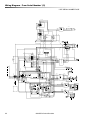
1
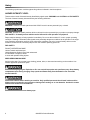
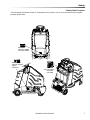
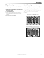
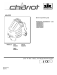
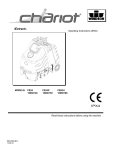
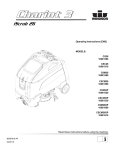
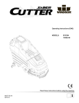
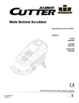
iGloss™
Operating instructions (ENG)
MODELS:
CB20
10020080
CBCD20
10020160
CBE20
10020100
CB20X
10020090
CBCD20X
10020210
From Serial #:
10020080000650
10020090000146
10020100000016
10020169000004
10020210000025
Read these instructions before using the machine.
86345050-U
02/21/14
Machine Data Label/Overview
Overview
The Chariot burnisher is a battery powered, ride-on, hard floor burnisher intended for commercial use. The
appliance applies a high luster to hard floor surfaces.
Warranty Registration
Thank you for purchasing a Windsor product. Warranty registration is quick and easy.
Your registration will allow us to serve you better over the lifetime of the product.
To register your product go to :
www.windsorind.com/WarrantyRegistration.aspx
For customer assistance:
1-800-444-7654
2
86345050 Chariot Burnisher
Table of Contents
Machine Data Label/Overview . . . . . . . . . . . . . . . . . 2
Table of Contents . . . . . . . . . . . . . . . . . . . . . . . . . . . 3
How to Use This Manual . . . . . . . . . . . . . . . . . . . . . . 4
Safety
IMPORTANT SAFETY INSTRUCTIONS . . . . . . . . . 5
Hazard Intensity Level . . . . . . . . . . . . . . . . . . . . . . . 6
Safety Label Location . . . . . . . . . . . . . . . . . . . . . . . . 7
Operations
How This Machine Works . . . . . . . . . . . . . . . . . . . . 10
Components . . . . . . . . . . . . . . . . . . . . . . . . . . . . . . 11
Drive Controls . . . . . . . . . . . . . . . . . . . . . . . . . . . . . 13
Burnisher Controls . . . . . . . . . . . . . . . . . . . . . . . . . 16
Pre-run Machine Inspection . . . . . . . . . . . . . . . . . . 18
Starting Machine . . . . . . . . . . . . . . . . . . . . . . . . . . . 18
Operating the Machine . . . . . . . . . . . . . . . . . . . . . . 18
Emergency Stop Procedure . . . . . . . . . . . . . . . . . . 18
To Begin Burnishing . . . . . . . . . . . . . . . . . . . . . . . . 19
Normal Burnishing . . . . . . . . . . . . . . . . . . . . . . . . . 19
Maintenance
Service Schedule . . . . . . . . . . . . . . . . . . . . . . . . . . 20
Batteries . . . . . . . . . . . . . . . . . . . . . . . . . . . . . . . . . 21
Batteries . . . . . . . . . . . . . . . . . . . . . . . . . . . . . . . . . 22
Battery Maintenance . . . . . . . . . . . . . . . . . . . . . . . . 22
Checking Battery Specific Gravity. . . . . . . . . . . . . . 23
Charging Batteries . . . . . . . . . . . . . . . . . . . . . . . . . 23
Changing Batteries . . . . . . . . . . . . . . . . . . . . . . . . . 24
Dust Bag Replacement . . . . . . . . . . . . . . . . . . . . . . 26
Dust Control Skirts Replacement . . . . . . . . . . . . . . 26
Pad Installation . . . . . . . . . . . . . . . . . . . . . . . . . . . . 26
Pad Driver Replacement. . . . . . . . . . . . . . . . . . . . . 27
Shunt Replacement . . . . . . . . . . . . . . . . . . . . . . . . 29
Burnisher Motor Carbon Brush Replacement . . . . . 29
Drive Motor & Brake . . . . . . . . . . . . . . . . . . . . . . . . 30
Electric Parking Brake Engagement . . . . . . . . . . . . 31
Drive Motor Carbon Brush Replacement . . . . . . . . 32
Troubleshooting . . . . . . . . . . . . . . . . . . . . . . . . . . . 34
Controller Fault Codes . . . . . . . . . . . . . . . . . . . . . . 35
Parts
Bumper . . . . . . . . . . . . . . . . . . . . . . . . . . . . . . . . .
Control Panel 1 . . . . . . . . . . . . . . . . . . . . . . . . . . .
Control Panel 2 . . . . . . . . . . . . . . . . . . . . . . . . . . .
Controls & Housing . . . . . . . . . . . . . . . . . . . . . . . .
Decals . . . . . . . . . . . . . . . . . . . . . . . . . . . . . . . . . .
Filter . . . . . . . . . . . . . . . . . . . . . . . . . . . . . . . . . . .
Frame-Lower. . . . . . . . . . . . . . . . . . . . . . . . . . . . .
Frame-Upper. . . . . . . . . . . . . . . . . . . . . . . . . . . . .
Hood . . . . . . . . . . . . . . . . . . . . . . . . . . . . . . . . . . .
Pedal Platform . . . . . . . . . . . . . . . . . . . . . . . . . . .
Pedal Platform-Mounting . . . . . . . . . . . . . . . . . . .
Rear Cover . . . . . . . . . . . . . . . . . . . . . . . . . . . . . .
Deck Lift Switches. . . . . . . . . . . . . . . . . . . . . . . . .
Deck Lift Mechanism. . . . . . . . . . . . . . . . . . . . . . .
Deck Lift Linkage . . . . . . . . . . . . . . . . . . . . . . . . .
Steering. . . . . . . . . . . . . . . . . . . . . . . . . . . . . . . . .
Steering. . . . . . . . . . . . . . . . . . . . . . . . . . . . . . . . .
Wheel-Front Drive-Chain . . . . . . . . . . . . . . . . . . .
Wheel-Front Brake . . . . . . . . . . . . . . . . . . . . . . . .
Wheel-Front Drive-Gear . . . . . . . . . . . . . . . . . . . .
Wheel-Rear . . . . . . . . . . . . . . . . . . . . . . . . . . . . . .
Wiring-Batteries . . . . . . . . . . . . . . . . . . . . . . . . . .
Wiring-Components . . . . . . . . . . . . . . . . . . . . . . .
Wiring-Control Panel . . . . . . . . . . . . . . . . . . . . . . .
Wiring-Drive Motor . . . . . . . . . . . . . . . . . . . . . . . .
Wiring-Main Harness . . . . . . . . . . . . . . . . . . . . . .
Wiring-Pedal Platform . . . . . . . . . . . . . . . . . . . . . .
Wiring Diagram . . . . . . . . . . . . . . . . . . . . . . . . . . .
Suggested Spare Parts . . . . . . . . . . . . . . . . . . . . .
38
40
42
44
46
48
50
52
54
56
58
60
62
64
66
68
68
70
72
74
76
78
80
82
84
86
88
90
91
Options
Back-up Alarm-Option. . . . . . . . . . . . . . . . . . . . . . 94
Battery Cart-Option . . . . . . . . . . . . . . . . . . . . . . . . 96
Seat-Option . . . . . . . . . . . . . . . . . . . . . . . . . . . . . 100
Warning Light-Option . . . . . . . . . . . . . . . . . . . . . 102
EC Declaration . . . . . . . . . . . . . . . . . . . . . . . . . . 104
Serial Numbers . . . . . . . . . . . . . . . . . . . . . . . . . . 105
86345050 Chariot Burnisher
3
How to Use This Manual
This manual contains the following sections:
•
•
•
•
•
The SAFETY section contains important information
regarding hazard or unsafe practices of the machine.
Levels of hazards are identified that could
HOW TO USE THIS MANUAL
SAFETY
OPERATIONS
MAINTENANCE
PARTS LIST
result in product or personal injury, or severe injury
resulting in death.
The HOW TO USE THIS MANUAL section will tell you
how to find important information for ordering correct
repair parts.
Model:
The OPERATIONS section is to familiarize the operator
with the operation and function of the machine.
The MAINTENANCE section contains preventive maintenance to keep the machine and its components in
good working condition. They are listed in this general
order:
•
•
•
•
•
•
Date of Purchase:
Serial Number:
Dealer:
Address:
Phone Number:
Sales Representative:
Parts may be ordered from authorized Windsor
dealers. When placing an order for parts, the machine
model and machine serial number are important. Refer
to the MACHINE DATA box which is filled out during the
installation of your machine. The MACHINE DATA box
is located on the inside of the front cover of this manual.
The model and serial number of your machine are
located below the battery compartment of the machine.
Service Schedule
Batteries
Brush Deck
Circuit Protection
Vacuum Motor
Drive Motor & Brake
The PARTS LIST section contains assembled parts
illustrations and corresponding parts list. The parts lists
include a number of columns of information:
REF - column refers to the reference number on the
parts illustration.
PART NO. - column lists the part number for the part.
PRV NO. - reference number.
QTY - column lists the quantity of the part used in that
area of the machine.
DESCRIPTION - column is a brief description of the
part.
SERIAL NO. FROM - If this column has an (*) and a
Reference number, see the SERIAL NUMBERS page
in the back of your manual. If column has two asterisk
(**), call manufacturer for serial number. The serial
number indicates the first machine the part number is
applicable to. The main illustration shows the most
current design of the machine. When a boxed illustration is shown, it displays the older design.
NOTES - column for information not noted by the other
columns.
NOTE: If a service or option kit is installed on your
machine, be sure to keep the KIT INSTRUCTIONS
which came with the kit. It contains replacement parts
numbers needed for ordering future parts
4
86345050 Chariot Burnisher
Safety
IMPORTANT SAFETY INSTRUCTIONS
When using an electrical appliance, basic precaution
must always be followed, including the following:
READ ALL INSTRUCTIONS BEFORE USING THIS MACHINE.
To reduce the risk of fire, electric shock, or injury:
Use only indoors. Do not use outdoors or expose to rain.
Use only as described in this manual. Use only manufacturer's recommended components and attachments.
If the machine is not working properly, has been dropped, damaged, left outdoors, or dropped into water, return it to
an authorized service center.
Do not operate the machine with any openings blocked. Keep openings free of debris that may reduce airflow.
This machine is not suitable for picking up hazardous dust.
Machine can cause a fire when operating near flammable vapors or materials. Do not operate this machine near
flammable fluids, dust or vapors.
This machine is suitable for commercial use, for example in hotels, schools, hospitals, factories, shops and offices
for more than normal housekeeping purposes.
Maintenance and repairs must be done by qualified personnel.
Disconnect battery before cleaning or servicing.
Before the machine is discarded, the batteries must be removed and properly disposed of.
Make sure all warning and caution labels are legible and properly attached to the machine.
During operation, attention shall be paid to other persons, especially children.
Before use all covers and doors shall be put in the positions specified in the instructions.
When leaving unattended, secure against unintentional movement.
The machine shall only be operated by instructed and authorized persons.
When leaving unattended, switch off or lock the main power switch to prevent unauthorized use.
This appliance has been designed for use with the brushes specified by the manufacturer. The fitting of other
brushes may affect its safety.
Do not use on surfaces having a gradient of over 10% (6 degrees).
SAVE THESE INSTRUCTIONS
86345050 Chariot Burnisher
5
Safety
The following symbols are used throughout this guide as indicated in their descriptions:
HAZARD INTENSITY LEVEL
There are three levels of hazard intensity identified by signal words -WARNING and CAUTION and FOR SAFETY.
The level of hazard intensity is determined by the following definitions:
WARNING - Hazards or unsafe practices which COULD result in severe personal injury or death.
CAUTION - Hazards or unsafe practices which could result in minor personal injury or product or property damage.
FOR SAFETY: To Identify actions which must be followed for safe operation of equipment.
Report machine damage or faulty operation immediately. Do not use the machine if it is not in proper operating
condition. Following is information that signals some potentially dangerous conditions to the operator or the equipment. Read this information carefully. Know when these conditions can exist. Locate all safety devices on the
machine. Please take the necessary steps to train the machine operating personnel.
FOR SAFETY:
DO NOT OPERATE MACHINE:
Unless Trained and Authorized.
Unless Operation Guide is Read and understood.
In Flammable or Explosive areas.
In areas with possible falling objects.
WHEN SERVICING MACHINE:
Avoid moving parts. Do not wear loose clothing; jackets, shirts, or sleeves when working on the machine. Use
Windsor approved replacement parts.
Batteries emit hydrogen gas. Explosion or fire can result. Keep sparks and open flame away. Keep battery
compartment open during charging. Keep sparks and flames away from the batteries. Do not smoke
around batteries.
Disconnect batteries before working on machine. Only qualified personnel should work inside machine.
Always wear eye protection and protective clothing when working on or near batteries. Avoid skin contact
with the acid contained in the batteries.
Never allow metal to lie across battery tops.
6
86345050 Chariot Burnisher
Safety
Safety Label Location
These drawings indicate the location of safety labels on the machine. If at any time the labels become illegible,
promptly replace them.
86244310
PRV NO. 500956
CAUTION LABEL
86243830 (2)
PRV NO. 500663
PINCH
CAUTION
86252520
PRV NO. 80885
BATTERY
CAUTION
86345050 Chariot Burnisher
7
Technical Specifications
ITEM
Nominal power
Rated Voltage
Rated Amperage
Batteries
Battery Compartment Dimensions
Propelling Motor
Mass (GVW)
Weight empty without batteries
Tires
Maximum Speed
Frame Construction
Brake
Minimum aisle u-turn width
Maximum rated climb and descent angle
8
DIMENSION/CAPACITY
3420 W
36 Volts DC
95 amps
3 X12 Volt 195-215 AH @ 20 hr. rate
21 in. x 16 in. x 17 in. tall (533mm x 406mm x 432mm)
.75 HP (560 W)
1,071 lbs (486 kg)
705 lbs (320 kg)
10" (254mm) Solid gray non-marking
3.5 miles/hour (5.6 Km/hour)
Powder coated steel
Electrical parking brake, sets automatically whenever operator
steps off platform or engages emergency stop.
56 in. (1425 mm)
7.5 degrees
86345050 Chariot Burnisher
Technical Specifications
ITEM
Height
Length
Width
Width of Burnishing Path
MEASURE
50.6 inches (1285 mm)
52.5 inches (1330 mm)
26.5 inches (670 mm)
20 inches (508mm)
WIDTH
LENGTH
HEIGHT
SPECIAL NOTES:
The sound pressure level at the operator's ear was
measured to be 68 dBA. This was a nearfield, broadband measurement taken in a typical industrial environment on a tile floor. This appliance contains no possible
source of impact noise. The instantaneous sound
pressure level is below 63 Pa.
The weighted root mean square acceleration at the
operator's arms was measured to be below 2.5m/s2.
This was a tri-axial, third-octave-band measurement
made during normal operation on a composite tile floor.
The measurement and related calculations were made
in accordance with ANSI S3.34-1986.
86345050 Chariot Burnisher
9
Operations
How This Machine Works
The Chariot is a battery powered, self propelled, hard
floor burnisher intended for commercial use. The
appliance spins a high-speed burnishing pad in contact
with the floor surface to produce a high luster shine.
The machines primary systems are the burnishing
system, the dust control system and the operator
control system.
The function of the burnishing system is to spin a highspeed burnishing pad in contact with a floor surface
that has had a burnishable floor finish applied. The
burnishing pad can be lowered to the floor and raised
by the operator, the operator can also control the pad
pressure by use of the pressure switch. The burnishing
pad will spin only when the machine is directed to move
by the operator.
The function of the operator control system is to control
the direction and speed of the machine. The directional
control system consists of the direction control switch,
throttle pedal, speed control switch, drive reset switch,
emergency stop/brake switch, steering wheel, propel
controller and drive wheel.The directional control
switch signals forward or reverse direction. The
controller interprets signals from the throttle pedal to
command the drive wheel to propel or slow the
machine. The drive reset switch is to make sure the
operator is on platform before machine will propel. The
steering wheel points the drive wheel in the direction
desired by the operator. The parking brake automatically engages when the operator steps off the platform.
The emergency stop/brake can be used to hold the
machine on slopes.
The function of the dust control system is to collect the
dust that is created during the burnishing process. It is
normal for a portion of the floor finish to be removed in
the form of dust during the process. While burnishing,
air movement is created within the burnishing head by
the spinning pad. The dust that is also created is
entrained in the air stream and transported to a filter
bag where it is collected and separated from the air
stream. The filter bag can be easily changed without
releasing the collected dust
10
86345050 Chariot Burnisher
Operations
2
1
6
5
8
4
3
7
Components
1. Control panel-Drive
5. Rear cover
2. Control Panel-Burnish
6. Cover
3. Control Housing
7. Filter Access Lid
4. Pedal Platform
8. Burnisher Deck
86345050 Chariot Burnisher
11
Operations
9
2
7
5
3
6
1
10
8
4
12
86345050 Chariot Burnisher
Operations
Drive Controls
6. Drive Reset Switch
1. Key Switch
7. Horn Button
2. Emergency Stop/Brake Switch
8. Steering Wheel
3. Directional Control Switch
9. Battery Charge level Indicator-Basic
4. Throttle Pedal
10. Hour Meter-Basic
5. Speed Control Switch
1. KEY SWITCH
Controls the power for machine functions.
To turn the machine power on, rotate key clockwise.
To turn the machine off, rotate key counterclockwise.
2. EMERGENCY STOP/BRAKE SWITCH
This safety feature is designed to cut all power to the machine at any time and apply parking brake.
To shut the machine power off, push the Emergency Stop Switch, this will also engage the parking brake and
cause the machine to stop immediately.
To reset the machine, rotate the switch clockwise.
3. DIRECTIONAL CONTROL SWITCH
Controls the direction of travel of the vehicle. The position of the switch indicates direction of travel.
To travel forward, press the top of the switch.
To travel in reverse, press the bottom of the switch.
4. THROTTLE PEDAL
Controls the speed of the vehicle within the speed control setting selected. Pressing the pedal causes the
machine to travel in the direction selected by the Directional Control Switch.
To increase speed, increase pressure on the pedal.
To decrease speed, decrease pressure on the pedal.
86345050 Chariot Burnisher
13
Operations
5. SPEED CONTROL SWITCH
Controls the maximum speed of the machine. There are two setting intended for scrubbing, speeds 1 and 2.
Speed 3 is recommended for transport only, not scrubbing.
To increase speed, press the top of the switch.
To decrease speed, press bottom of the switch. Speeds can be adjusted at any time, whether machine is
moving or not.
Basic: The position of the switch indicates speed setting.
Deluxe: The display indicates speed setting. When the key is turned on the controller will automatically adjust
the speed to setting 2.
6. DRIVE RESET SWITCH
This safety feature is designed to ensure safe engagement of propel drive. Each time the machine power is
turned on, and each time an operator steps on to the platform, the Drive Reset Switch must be pushed before
machine will propel.
7. HORN BUTTON
The horn is activated by pressing the horn button.
8. STEERING WHEEL
The steering wheel turns the front wheel causing the machine to change direction.
9. BATTERY CHARGE LEVEL INDICATOR-BASIC
Indicates the charge level of the batteries.
The meter display is divided into 10 vertical bars. Bars illuminated on the far right indicate full charge. Bars
flashing near the left side indicate the batteries should be recharged. Further operation of the machine could
damage the machine or the batteries.
If the batteries are not fully recharged, the meter will continue to flash on the left side.
10. HOUR METER-BASIC
Records the number of hours the machine has been in operation. This information is useful in determining
when to service the machine.
14
86345050 Chariot Burnisher
Notes
86345050 Chariot Burnisher
15
Operations
1
2
3
Burnisher Controls
1. Deck On/Off Switch
2. Pad Pressure Switch
3. Pad Pressure Meter
16
86345050 Chariot Burnisher
Operations
1. DECK ON/OFF SWITCH
Raises/lowers burnisher head.
To lower head, press the bottom of the switch. To raise head, press the top of the switch.
The motor will run only when the head is down and the machine is propelling.
2. PAD PRESSURE SWITCH
Press switch to adjust pad pressure.
3. PAD PRESSURE METER
Indicates relative pad pressure. "Green area" indicates proper pad pressure range.
86345050 Chariot Burnisher
17
Operations
Pre-run Machine Inspection
Operating the Machine
Do a pre-run inspection to find possible problems that
could cause poor performance or lost time from breakdown. Follow the same procedure each time to avoid
missing steps.
1. Lower or raise deck by pressing burnishing head
switch.
NOTE: See maintenance section for pre-run machine
inspection checklist items.
Starting Machine
NOTE: Perform pre-run machine check before
operating machine.
FOR SAFETY: Before starting machine, make
sure that all safety devices are in place and
operating properly.
1. Disconnect the battery charger.
2. The pad motor will only run when the burnishing
head is lowered to within 2 inches of the floor.
3. The pad pressure is adjusted using the pressure
switch at right of panel. The operator monitors the
amp draw using the meter located on the control
panel and ensures that the needle remains in the
“green” operating range.
To prevent possible damage to the floor surface,
always keep the machine moving while the pad is
spinning.
4. When the head is down and the machine is
propelled, the pad motor runs.
3. Turn or install a new burnishing pad as needed.
5. Return the machine to the battery charger when
the battery light indicator meter indicates
discharged batteries
4. Stand on the operator platform. Throttle pedal must
be in neutral position.
Emergency Stop Procedure
2. Close the cover.
5. Turn the machine power on by turning key switch
clockwise to the “ON” position.
6. Check the position of the Directional Control
Switch to make sure the machine will travel in the
direction intended.
7. Press the Drive Reset Switch.
8. Press lightly on the throttle pedal with right foot.
18
Release the throttle pedal by lifting right foot.
Turn machine power off with key switch, by turning key
switch counterclockwise.
If an electrical problem is suspected, push in
emergency stop button. This will also engage the
parking brake and cause the machine to stop immediately.
86345050 Chariot Burnisher
Operations
To Begin Burnishing
Normal Burnishing
When operating the machine around people, pay close
attention for unexpected movement. Use extra caution
around children.
Plan the burnishing pattern in advance. The longest
track is around the perimeter of the area to be
burnished. For efficient operation, the runs should be
the longest possible without turning, stopping, or
raising or lowering the burnisher head.
1. Stand on the operator platform. Throttle pedal must
be in neutral position.
2. Turn machine power on.
3. Check position of Directional Control Switch to
ensure that machine is set to travel in direction
intended.
In order to achieve the best possible results, the area
which is to burnished should be swept before
burnishing.
INEFFICIENT BURNISHING PATH
4. Press the Drive Reset Switch.
RECOMMENDED BURNISHING PATH
86345050 Chariot Burnisher
19
Maintenance
Service Schedule
BEFORE
EACH WORK
PERIOD
MAINTENANCE
Check water level of batteries after charging; add distilled
water if necessary.
Visually check for damaged or worn tires.
Check pad for proper installation.
Check dust vacuum hose connections.
Check pedal(s), brake and steering for proper operation.
Check dust bag.
Charge batteries.
Clean off top of batteries.
Check battery cells with hydrometer.
Check battery connections are tight.
Clean battery cases and battery compartment.
Clean and check drive tension chain for wear and tension.
Check parking brake.
Clean pivot points on burnishing head.
Check drive motor for carbon brush wear.
Check steering chain tension.
50
100
HRS HRS
200
HRS
*
*
*
*
*
The pad drive motor contains no carbon brushes and requires not service.
20
AFTER
EACH
WORK
PERIOD
86345050 Chariot Burnisher
*
*
*
*
*
*
*
*
*
*
*
Maintenance
1
2
3
4
5
6
Batteries
1. Rear Cover Retainer Handle
4. Batteries
2. Rear Cover
5. Battery Tray
3. Battery Connector-Machine
6. Battery Tray Latch
86345050 Chariot Burnisher
21
Maintenance
Batteries
The batteries provide the power to operate the
machine. The batteries require regular maintenance to
keep them operating at peak efficiency.
The machine batteries will hold their charge for long
periods of time, but they can only be charged a certain
number of times. To get the greatest life from the
batteries, charge them when their charge level reaches
25% of a full charge. Use a hydrometer to check the
charge level.
Do not allow the batteries to remain in a discharged
condition for any length of time. Never expose a
discharged battery to temperatures below freezing.
Discharged batteries will freeze causing cracked
cases. Do not operate the machine if the batteries are
in poor condition or if they have a charge level below
25% (specific gravity below 1.155).
Keep all metallic objects off the top of the batteries, as
they may cause a short circuit. Replace worn or
damaged cables and terminals.
Check the electrolyte level in each battery cell before
and after charging the batteries. Never add acid to the
batteries, use distilled water. Do not allow water level to
fall below the battery plates. Portions of plates exposed
to air will be destroyed. Do not overfill. Keep plugs
firmly in place at all times.
When servicing machine, avoid contact with battery
acid.
Batteries emit hydrogen gas. Explosion or fire can
result. Keep sparks and open flame away. Keep covers
open when charging.
Wear eye protection and protective clothing when
working with batteries.
Charge batteries in a well ventilated area.
Battery Maintenance
1. When cleaning the batteries, use a solution of
baking soda and water. Do not allow the cleaning
fluid to enter the battery cells, electrolyte will be
neutralized.
2. Maintain the proper electrolyte level in each battery
cell. If a cell should accidentally overflow, clean
immediately.
3. Wipe off the top of the batteries at least once a
week.
4. Test battery condition with a hydrometer at least
once a week.Test battery condition with a hydrometer at least once a week.
5. Ensure that all connections are tight and all
corrosion removed.
6. Every 4 to 6 months, remove that batteries from
the machine and clean the battery cases and
battery compartment.
22
86345050 Chariot Burnisher
Maintenance
Checking Battery Specific Gravity
Charging Batteries
Use a hydrometer to check the battery specific gravity.
When servicing machine, avoid contact with
battery acid.
Batteries emit hydrogen gas. Explosion or fire can
result. Keep sparks and open flame away. Keep
covers open when charging.
Wear eye protection and protective clothing when
working with batteries.
NOTE: Do not take readings immediately after adding
distilled water, if the water and acid are not
thoroughly mixed, the reading may not be accurate.
Check the hydrometer readings against this chart.
SPECIFIC GRAVITY @
80° F (27°C)
BATTERY CONDITION
1.265
100% CHARGED
1.225
75% CHARGED
1.190
50% CHARGED
1.155
25% CHARGED
1.120
DISCHARGED
NOTE: If the readings are taken when the battery
electrolyte is any temperature other than 80°F (27°C),
the reading must be temperature corrected.
To find the corrected specific gravity reading when the
temperature of the battery electrolyte is other than 80°F
(27°): Add (+) to the specific gravity reading 0.004 (4
points), for each 10°F (6°C) above 80° (27°C).
Subtract (-) from the specific reading 0.004 (4 points),
for each 10°F (6°C) below 80°F (27°C).
Charge batteries in a well ventilated area.
Use a 36 volt, 20 amp maximum output DC charger
which will automatically shut off when the batteries are
fully charged.
1. Empty recovery tank.
2. Stop the machine in a clean, well ventilated area
next to the charger.
3. Turn “OFF” machine.
FOR SAFETY: Before leaving or servicing machine;
stop on level surface, turn off machine and remove
key.
4. Unplug the machine from the battery pack.
Remove front cover. Disconnect recovery hose
from “Y” tube. Raise recovery tank and verify prop
rod latch is safely engaged.
Batteries emit hydrogen gas. Explosion or fire can
result. Keep sparks and open flame away. Keep
covers open when charging.
5. Check the electrolyte level in each battery cell.
Before charging, add just enough distilled water to
cover the plates. After charging is complete, add
just enough distilled water to bring up the level to
the indicator ring. If the water level is too high
before charging, normal expansion rate of the electrolyte may cause an overflow resulting in a loss of
battery acid balance and damage the machine.
86345050 Chariot Burnisher
23
Maintenance
5. Replace the battery caps, and leave them in place
while charging.
6. Unplug the battery connector from the machine.
SAFTEY: When charging, connect the charger to the
batteries before connecting the charger to the AC
wall outlet. Never connect the charger to the AC wall
outlet first. Hazardous sparks may result.
7. Plug the charger connector into the battery
connector. Connect the charger AC plug to a wall
outlet. The charger gauge should indicate that the
batteries are charging.
Changing Batteries
Stop the machine in a clean area next to the charger.
Turn off machine.
SAFETY: Before leaving or servicing the machine;
stop on level surface, turn off machine and remove
key.
1. Remove the rear cover.
2. Disconnect battery pack from machine.
3. Unlatch battery tray from machine and pull out to
expose batteries.
8. When the batteries are fully charged, disconnect
the charger from the AC wall outlet, then disconnect the charger from the batteries.
4. Use the proper size open end wrench to disconnect main ground wire first and secure cable
terminal away from batteries.
9. Connect the batteries to the machine connector.
5. Disconnect main positive lead and secure cable
terminals away from batteries.
10. Check the electrolyte level. It should be up to the
indicator ring. If necessary, add distilled water.
11. Install the rear cover.
6. Loosen both terminals on each jumper cable and
remove one at a time.
7. Prepare a suitable site to place the batteries.
8. Attach suitable battery lifting device and lift
batteries from the machine.
Batteries are a potential environmental hazard.
Consult your battery supplier for safe disposal
methods.
RED
+
BLK
-
RED
+
BLK
-
RED
+
BLK
-
REAR OF MACHINE
24
86345050 Chariot Burnisher
Maintenance
1
3
2
1. Dust Bag/Filter
2. Pads
3. Skirts
86345050 Chariot Burnisher
25
Maintenance
Dust Bag Replacement
Pad Installation
1. Raise cover to expose filter cover.
Install pad using the pad centering tool (86064370 PRV NO. 66829).
2. Using lifting access hole, lift bag cover.
3. Carefully remove bag from hose.
4. Slide a new bag onto hose. Ensure bag is pushed
on so that top of bag rest on top lip of filter cover.
Dust Control Skirts Replacement
1. Replace skirts when worn, torn, or damaged in any
way that allows dust to escape.
1. Lay the pad in the pan and position under the pad
driver. The edges of the pan will align the pad and
driver.
2. Screw the center lock in place through the hole in
the pan. The center lock has a right hand thread.
3. The pad centering tool can be stored under the
hood.
2. Remove skirt strips by pulling down.
3. Insert new skirt strips and snap them into place.
PAD
PAD CENTERING
TOOL
CENTER LOCK
SNAP OUT
SNAP IN
26
86345050 Chariot Burnisher
Maintenance
Pad Driver Replacement
Turn key switch on to lower deck down. Use needle
nose vise grips to clamp together spring retainer bars
between spring.
Remove the four bolts holding deck assembly onto
frame. Two bolts on each side.
Label and remove wires coming off of motor. Disconnect by unplugging motor wire harness from machine
wire harness. Take note cable tie locations.
Slide deck out from under machine and turn deck
assembly over on to motor. Remove pad lock and pad.
Attach metal ring (86082070 - PRV NO. 629000) using
same screws that held pad lock keeper. Screw in
spacer (862454470 - PRV NO. 739000) into motor
shaft.
86345050 Chariot Burnisher
27
Maintenance
Use Gear puller to remove pad driver from motor shaft.
Take care not to misplace motor shaft key.
Install new pad driver, motor shaft key, spacer, washer
and bolt. Then install pad lock keeper, pad and pad
lock. Turn deck assembly over onto pad.
5 3/16
Reattach wires to motor and connect motor wire
harness to frame harness. Tie wires in place. Set
actuator barrel by rotating barrel up or down to set
barrel at 5-3/16 ±1/8 from bottom of frame to bottom of
barrel.
Reattach deck assembly to frame. Install actuator
barrel on to spring retainer bars. Lift bottom of deck
using your hand to align hole for clevis pin. Install clevis
and rue ring.
Turn machine on, raise deck, drive machine check that
machine is working properly. If not recheck actuator
barrel and reset again if needed.
28
86345050 Chariot Burnisher
Maintenance
Shunt Replacement
This pad pressure meter adjustment is factory set. Over
the course of time it may become necessary to adjust
this setting using the slotted connection on the shunt.
Slotted
Connection
From
Meter
To
Meter
Moves
needle
toward
RED
range
Moves
needle
toward
GREEN
range
SHUNT
See wiring diagram for lead connection
Burnisher Motor Carbon Brush
Replacement
1. Mark location of cable lugs on motor housing.
2. Remove four screws from top cover. Remove
cover from motor.
3. Remove four screws from brush housing. Lift brush
housing off of motor commutator.
4. Clean excessive carbon deposits off of motor
components with compressed air.
5. Prepare new brush assembly for use by inserting
individual brush springs into brush guides. Check
each brush to ensure proper movement after
installing springs.
Check the amp range when nuisance tripping of the
pad motor controller indicates that the shunt may be out
of adjustment.
6. Locate new brush assembly according to locations
marked in step 1. Depress brushes as required to
insert brush housing over commutator.
1. Connect a DC ampere meter to the positive battery
7. Check that motor spins freely with new brushes
installed. Replace four screws to secure brush
housing. Replace motor cover.
0
60
GREEN
RED
APPROX. AMP RANGE
lead. Running the machine with a pad, lower the
pad to the floor until it is operating at 60 5 amps.
2. Moving the wire in the slot, adjust the pad pressure
meter until the needle sets at the line between the
blue and red areas.
86345050 Chariot Burnisher
29
Maintenance
2
1
3
Drive Motor & Brake
1. Drive Motor
2. parking Brake
3. Drive Chain
30
86345050 Chariot Burnisher
Maintenance
Electric Parking Brake Engagement
To disengage brake:
FOR SAFETY: Before leaving or servicing machine,
stop on a level surface, turn off machine and remove
key.
Electric Brake Engagement
This machine is equipped with an electric parking
brake.
The brake automatically engages and keeps the
machine from moving whenever the operator steps off
the platform or when emergency stop is engaged.
The brake has a mechanical over-ride that can be
engaged so machine can be pushed or towed (slowly).
When the mechanical over-ride is engaged the
machine cannot be driven.
1. Mechanical over-ride disengaged Machine can be
driven.
To engage brake:
2. Push lever firmly in direction of arrow.
1. Mechanical over-ride engaged.Machine can be
pushed or towed (slowly).
2. Push lever firmly in direction of arrow
NOTE: There is an intermediate stop. Make sure
lever is fully in the down position.
86345050 Chariot Burnisher
31
Maintenance
Drive Motor Carbon Brush Replacement
Do not use a pressure washer to clean around the
motors. Use tap pressure only.
FOR SAFETY: Before leaving or servicing
machine, stop on a level surface, turn off machine
and remove key.
7. Install new brush and reinstall connecting screw
and lead.
8. When all new brushes are installed. Place all in
retracted position, held into brush holder by spring
tension.
9. Carefully replace brush cap.
1. Disconnect batteries from machine.
Reinstalling:
2. Disconnect the electrical connection to the traction
motor.
10. When replacing the hex hub, use a small pin or
screw to help align the holes.
BRAKE REMOVAL
(Must be done to access carbon brushes)
11. Drive the pin into the hub and make sure it is flush
to the hex surface. The brake will not fit on the hub
if the roll pin is protruding from the hub.
3. Remove 4 mounting screws and remove brake.
12. Replace the hub and use Lock-Tite on the screws.
4. Drive roll pin out of the hex hub enough to allow
hex hub to slide off shaft. Its is recommended that
the roll pin be left partially in the hex hub.
ROLL PIN
HEX HUB
SMALL PIN OR SCREW
5. Remove brush cap.
6. Release brush from spring tension. Remove screw
connecting brush wire lead to brush holder. Clean
brush holder to insure free movement.
32
86345050 Chariot Burnisher
Maintenance
Circuit Breakers
1. Circuit breakers interrupt the flow of power in the
event of an electrical overload. When a circuit
breaker is tripped, reset it by pressing the exposed
button. If a circuit breaker continues to trip, the
cause of the electrical overload should be found
and corrected.
30 Amp. Protects the propel motor.
2. The burnisher motor breaker is a resetable circuit
protection device, designed to stop the flow of electrical current to the burnisher pad motor in the
event of an electrical overload. This protects the
pad motor. If breaker is tripped, allow breaker to
cool for several minutes. Once the breaker has
cooled, reset by returning red flag to upward
position.
The breaker is located inside the battery compartment as shown.
3 Amp. Protects the machine controls.
(Basic only).
86345050 Chariot Burnisher
33
Maintenance
Troubleshooting
PROBLEM
No power to machine
Little or no propel
Battery disconnected
Emergency shut-off activated
Battery cables corroded
Faulty key switch
Low battery charge
Machine turned on with pedal not in
neutral position
Tripped circuit breaker
Controller overheated
Loose motor connection
Faulty throttle circuit or potentiometer
Faulty drive reset circuit or switch
Faulty platform circuit or switch
Brake over-ride engaged
Faulty brake circuit or over-ride switch
Forward speed only
Reverse speed only
Deck won't go up or down
Pad motor won't run
Check all battery cable connections
Reset
Clean connections
Replace switch
Charge batteries
Allow pedal to return to neutral. Restart
Reset circuit breaker
Allow cool down period
Check wires and connections from
controller to motor
Check wires and connections from
throttle to controller and potentiometer
resistance
Check wires, connections and switch
Check wires, connections and switch
Disengage brake over-ride
Check wires, connections and switch
Faulty forward/reverse switch
Replace switch
Circuit breaker tripped
Circuit breaker tripped
Faulty switch or connection
Faulty relay
Reset circuit breaker
Reset circuit breaker
Check switch or connections
Check pad motor relay
Re-center or replace pad using pad
install tool
Check for blockage and clear if needed
Deck vibrates
Pad off center
Dust leaks from skirts
Dust hose blocked
34
SOLUTION
CAUSE
86345050 Chariot Burnisher
Maintenance
Controller Fault Codes
LED
CODE
PROGRAMMER LCD
DISPLAY
EXPLANATION
POSSIBLE CAUSE
1. Temperature >92°C or < -25°C.
1,1
over-/under-temperature
cutback
THERMAL CUTBACK
2. Excessive load on vehicle.
3. Operation in extreme environments.
4. Electromagnetic brake not releasing.
1. Throttle input wire open or shorted.
1,2
THROTTLE FAULT 1
throttle fault
1,3
SPD LIMIT POT FAULT
speed limit pot fault
1,4
LOW BATTERY VOLTAGE
battery voltage too low
1,5
OVERVOLTAGE
battery voltage too high
MAIN OFF FAULT
main contactor driver Off
fault
2. Throttle pot defective.
3. Wrong throttle type selected.
1. Speed limit pot wire(s) broken or shorted.
2. Broken speed limit pot.
1. Battery voltage >17 volts.
2. Bad connection at battery or controller.
1. Battery voltage>36 volts.
2. Vehicle operating with charger attached.
3. Intermittent battery connection.
2,1
1. Main contactor driver failed open.
1.Main contactor welded or stuck open.
2,3
MAIN CONT FLTS
main contactor fault
MAIN ON FAULT
main contactor driver On
fault
2. Main contactor driver fault.
3. Brake coil resistance too high.
2,4
86345050 Chariot Burnisher
1. Main contactor driver failed closed.
35
Maintenance
LED
CODE
PROGRAMMER LCD
DISPLAY
EXPLANATION
POSSIBLE CAUSE
1. Misadjusted throttle.
3,1
PROC/WIRING FAULT
HPD fault present for >10
sec.
3,2
BRAKE ON FAULT
brake On fault
3,3
PRECHARGE FAULT
precharge fault
3,4
BRAKE OFF FAULT
brake Off fault
3,5
HPD
HPD (High pedal
Disable) fault
4,1
CURRENT SENSE FAULT
current sense fault
4,2
HW FAILSAFE
motor voltage fault (hard2. Short in motor or in motor wiring.
ware)
2. Broken throttle pot or throttle mechanism.
1. Electromagnetic brake driver shorted.
2. Electromagnetic brake coil open.
1. Low battery voltage.
2.KSI and throttle turned on at same time.
1. Electromagnetic brake driver open.
2. Electromagnetic brake coil shorted.
1. Improper sequence of throttle and KSI.
2. Misadjusted throttle pot.
1. Short in motor or in motor wiring.
2. Controller failure.
1. Motor voltage does not correspond to
throttle request.
4,3
EEPROM FAULT
EEPROM fault
3. Controller failure.
1. EEPROM failure or fault.
1. EEPROM failure or fault.
4,4
POWER SECTION FAULT
power section fault
2. Short in motor or in motor wiring.
3. controller failure.
36
86345050 Chariot Burnisher
Parts
Burnisher
Parts
86345050 Chariot Burnisher
37
Bumper
10
1
2
7
8
7 10 9
6
6
11
3
5
1
4
38
86345050 Chariot Burnisher
Bumper
REF
PART NO.
PRV NO.
QTY
1
2
3
4
5
6
7
8
9
10
11
86276890
86007070
86063230
86063240
86071020
86270830
86010670
86070730
86197040
86279130
86251750
70752
70849
140813
140814
140783
57023
87029
140729
57264
87083
67602
6
2
1
1
1
4
4
2
4
4
2
DESCRIPTION
SERIAL NO.
FROM
NOTES:
SCR, 5/16-18X3/4 PTHMS SS
SCR, #12 X 1.25 PPHMS SS
BUMPER, LEFT
BUMPER, RIGHT
BRKT, FRONT BUMPER
NUT, 5/16-18 HEX NYLOCK SS
WASHER, 5/16 FLAT SS
BRKT, BUMPER MOUNT, SIDE
NUT, 5/16-18 HEX ACORN PLTD
WASHER, 5/16 SPLIT LOCK
RISER, BUMPER
86345050 Chariot Burnisher
39
Control Panel 1
18
19
1
17
3
2
4
5
6
16
8
10
7
11
15
9
8
8
14
40
13
12
86345050 Chariot Burnisher
Control Panel 1
REF
PART NO.
PRV NO.
QTY
1
2
3
4
5
6
86223740
86340020
86340030
86006530
86273820
86277480
70872
70057
70019
70850
2
1
1
2
2
3
7
86008760
80682
1
8
9
10
11
12
13
14
15
16
86005810
86070720
86271840
86279130
86271120
86010670
86005700
86371450
86005700
80682
140728
57285
87083
57125
87029
57104
57104
6
1
3
2
2
2
1
1
2
17
86027740
27911
1
18
19
86273980
86340880
70066
-
2
1
DESCRIPTION
SCR, 1/4-20 X .59 PPHMS SS C
COVER, PANEL MNT BREAKER
BREAKER, 100A CIRCUIT
SCREW 1/4-20 X 1 PPHMS SS
SCREW 1/4-20 X 1.25 HHCS SS
SCREW 5/16-18X1/2 PTHMS SS
CONNECTOR 175 DCA GRY W/O
TERMS
NUT 1/4-20 HEX NYLOCK SS
BRKT, BATT CONN, BASIC
NUT 5/16-18 HEX NYLOCK THIN SS
WASHER 5/16 SPLIT LOCK PLTD
NUT, 5/16-18 BRASS
WASHER 5/16 FLAT SS
NUT 10-32 W/STAR WASHER PLTD
RELAY 36VDC 100A HD
NUT 10-32 W/STAR WASHER PLTD
SP CONTROLLER, CE24
PROGRAMMED
SCREW 10-32 X 3/4 PPHMS SS
PANEL, BURNISHER
SERIAL NO.
FROM
NOTES:
(4)*
* SEE SERIAL NUMBER PAGE
86345050 Chariot Burnisher
41
Control Panel 2
22
1
21
2
23
24
3
14
5
7
20
6
4
19
10
18
17
10
13
12
16
11
15
8
14
10
9
10
42
86345050 Chariot Burnisher
10
Control Panel 2
REF
PART NO.
PRV NO.
QTY
DESCRIPTION
1
2
3
4
5
6
7
8
9
10
86257110
86007140
86007190
86257140
86257280
86008900
86002010
86007180
86251410
86255900
72189
72130
72161
72196
81371
80845
14942
72160
67506
73538
1
1
1
1
1
1
1
1
1
10
11
86246930
54144
1
12
13
14
15
16
17
18
19
20
21
22
23
24
86005530
86001910
86273990
86279300
86002000
86229770
86237830
86249290
86251410
86007210
86007130
86246920
86007130
51454
14606
70067
87134
14717
140805
35264
62283
67506
72165
72128
54131
72128
1
1
4
2
1
1
1
1
2
1
1
2
1
SWITCH 4P3T FIXED POS ROCKER
SWITCH SPST 2-POSITION ROCKER
SWITCH KEY DPST
SWITCH ASM, SEALED PB RND GRN
SWITCH, PUSH BUTTON
BOOT, SEAL-PUSH BUTTON 7/16-28
BOOT, 3/8 CIRCUIT BREAKER
SWITCH EMERGENCY STOP
RELAY 15A 36V MINI
STANDOFF, 6-32 X 5/8 HEX NYL
METER,36V BATTERY CHARGE
LEVEL
METER, 12-48 VDC LED HOUR
BREAKER, 30A 50VDC CIRCUIT
SCREW 6-32 X 3/8 PPHMS
SS
WASHER, #6 LOCK
BREAKER, 3 AMP 1681-090-300
BLOCK, SHUNT MOUNT
GASKET, AMP METER
PLATE, METER RETAINING
RELAY 15A 36V MINI
SWITCH DPDT 3-POSITION ROCKER
SWITCH DPDT 2-POSITION ROCKER
METER 0-70 AMP DC L2020B
SWITCH DPDT 2-POSITION ROCKER
86345050 Chariot Burnisher
SERIAL NO.
FROM
NOTES:
43
Controls & Housing
8
19
16
17
18
20
21
9
22
DETAIL 'A'
1
2
2
4
10
5
15
14
3
5
6
13
12
7
11
10
SEE DETAIL 'A'
44
86345050 Chariot Burnisher
Controls & Housing
REF
PART NO.
PRV NO.
QTY
DESCRIPTION
1
2
3
4
5
6
7
8
9
10
11
12
13
14
15
16
17
18
19
20
21
22
86290540
86277480
86070710
86062220
86010670
86223740
86273980
86270990
86229770
86005810
86340270
86279750
86089650
86070700
86277420
86253600
86010780
86005710
86273980
86276250
86279600
86271790
70850
140726
270117
87029
70872
70066
57090
140805
57245
87252
78524
140725
70841
73445
87162
57105
70066
70615
87187
57256
6
2
1
1
1
2
2
2
1
2
1
4
4
1
4
1
2
2
2
2
2
2
SCREW, 10-32 X .5 TMS SS BLK TL
SCREW, 5/16-18 X .5 PHTRHMS SS
BRKT, LEFT CONSOLE MOUNT
CONSOLE, BURNISHER
WASHER 5/16 FLAT SS
SCR, 1/4-20 X .59 PPHMS SS C
SCREW, 10-32 X .75 PHPNHMS SS
NUT, 10-32 HEX NYLOCK SS
BLOCK, SHUNT MOUNT
NUT, 1/4-20 HEX NYLOCK SS
RELAY, 200A
NUT, 5/16 PUSH STL ZNPLT
TUBE,5/8 OD X .357 ID X 1.57
BRKT, RIGHT CONSOLE MOUNT
SCREW, 5/16-18 X 2.5 PHTRHMS SS
SHUNT, 50MV 70AMP
WASHER, 1/4 X .487 X .062 SPL STL ZNPLT
NUT, 1/4-20 HEXSTRW LK STL ZNPLT
SCREW, 10-32 X .75 PHPNHMS SS
SCREW, 6-32 X .375 SLTDPNHMS BRS
WASHER, 6 X .312 X .025 FLT BRS
NUT, 6-32 HEX BRS
86345050 Chariot Burnisher
SERIAL NO.
FROM
NOTES:
45
Decals
6 4
5
3
2
1
7
46
86345050 Chariot Burnisher
Decals
REF
PART NO.
PRV NO.
QTY
1
2
3
4
5
6
7
86004970
86244760
86244770
86244190
86340940
86243990
86244350
50990
501224
501225
500882
500780
501050
1
1
1
1
1
1
1
DESCRIPTION
SERIAL NO.
FROM
NOTES:
LABEL, WINDSOR LOGO DOMED
DECAL, CHARIOT SIDE IGLOSS RT
DECAL, CHARIOT, SIDE IGLOSS LT
LABEL, PANEL BASIC LEFT
LABEL, PANEL DECAL , RH
LABEL, COVER PANEL
LABEL, PAD ALIGNMENT
Note: See “Saftey Label Location” page for safety label information.
86345050 Chariot Burnisher
47
Filter
DETAIL 'A'
6
5
4
DETAIL 'A'
7
8
3
11
2
9
7
10
1
12
48
86345050 Chariot Burnisher
Filter
REF
PART NO.
PRV NO.
QTY
1
2
3
4
5
6
7
8
9
10
11
12
86271820
86276890
86340170
86072500
86002380
86240320
86270990
86284870
86063790
86072510
86002840
86006590
57270
70752
14398
20046
39729
57090
2003SM
27880
14399
27282
70088
3
2
1
1
1
1
2
1
1
1
1
1
DESCRIPTION
SERIAL NO.
FROM
NOTES:
NUT 5/16-18 CAPTIVE "J” PLTD
SCREW 5/16-18X3/4 PTHMS SS
PLATE, FILTER MOUNT
BRKT, FILTER COVER LATCH
CLAMP, 2.25" WORM GEAR
HOSE ASM, 1.5 BLK VAC X 3
NUT 10-32 HEX NYLOCK SS
SM FILTER BAG PACKS 10/PKG
COVER FILTER
BRKT, FILTER COVER HINGE
CUFF, 1.5 SLIP X 1.5 HOSE
SCREW 10-32 X 1/2 PPHMS SS NP
86345050 Chariot Burnisher
49
Frame-Lower
14
16
17
15
12
13
1
9
11
2
4
3
3
3
8
5
3
10
3
9
9
6
21
3
23
27
3
86345050 Chariot Burnisher
22
25
6
50
7
24
18
19 20
9
26
Frame-Lower
REF
PART NO.
PRV NO.
QTY
1
2
3
4
5
6
7
8
9
10
11
12
13
14
15
16
17
18
19
20
21
22
23
24
25
26
27
86300060
86088760
86270830
86071430
86071120
86010670
86064300
86070740
86276070
86091420
86088750
86277470
86071130
86070750
86070760
86279130
86197040
86079290
86010630
86271870
86276950
86079320
86277130
86276910
86001350
86011020
86300100
75458
57023
140863
140811
87029
140790
140730
70593
05251
75457
70848
140812
140731
140733
87083
57264
620097
87013
57290
70772
620101
70795
70754
140390
89202
-
1
1
21
1
1
5
2
1
16
1
1
6
1
1
1
4
4
2
4
4
4
2
2
1
2
2
1
DESCRIPTION
SERIAL NO.
FROM
NOTES:
FRAME, MAIN ASM
TRAY, SLIDE, LEFT
NUT, 5/16-18 HEX NYLOCK SS
BRKT, BRACE, RGT FRONT
BRKT, TIP BRACE, RIGHT, REAR
WASHER, 5/16 FLAT SS
PAD, TIPPING BAR
BRKT, LINKAGE, RIGHT
SCR, 5/16-18 X 3/4 CARRIAGE SS
AXLE, REAR WELDMENT
TRAY, SLIDE, RIGHT
SCR, 5/16-18 X 1.5 CARRIAGE SS
BRKT, TIP BRACE, LEFT, REAR
BRKT, LINKAGE, LEFT
BRKT, BRACE, LEFT FRONT
WASHER, 5/16 SPLIT LICK PLTD
NUT, 5/16-18 HEX ACORN PLTD
PLATE, REAR COVER ADJ.
WASHER, 1/4 ID X 5/8 OD SS
NUT, 1/4-20 HEX NYLOCK THIN SS
SCR, 1/4-20 X 3/4 CARRIAGE SS
PLATE, PAD RETAINER
SCR, 5/16-18 X 1.00 CARRIAGE SS
SCR, 5/16-18 X 3 HHCS SS NP
BUSHING, SPANNER .435 X 1.10
WHEEL, 3" DIA CUSHION RUBBER
BRKT, WHEEL MOUNT
86345050 Chariot Burnisher
51
Frame-Upper
1
2
3
2
3
2
4
5
4
7
2
9
4
2
3
6
8
4
3
2
4
3
52
86345050 Chariot Burnisher
Frame-Upper
REF
PART NO.
PRV NO.
QTY
1
2
3
4
5
6
7
8
9
86071360
86270830
86010670
86276070
86083080
86074160
86073500
86277460
86238450
140855
57023
87029
70593
66437
270101
270090
70847
36245
1
10
9
9
1
1
1
2
1
DESCRIPTION
SERIAL NO.
FROM
NOTES:
BRKT, HORIZ ELECT, BURNISHER
NUT, 5/16-18 HEX NYLOCK SS
WASHER, 5/16 FLAT SS
SCR, 5/16-18 X 3/4 CARRIAGE SS
PLATE, VERT BEARING SUPPORT
CHANNEL, RIGHT DELUXE
BRKT, SIDE CHANNEL L
SCR, 5/16-18 X 5/8 BSHCS SS
GROMMET, 3.0 ID X 3.25 GROOVE
86345050 Chariot Burnisher
53
Hood
12
10
11
7
6 5
13
15
6
8
9
5
1
2
4
3
14
16
1
54
86345050 Chariot Burnisher
Hood
REF
PART NO.
PRV NO.
QTY
1
2
3
4
5
6
7
8
9
10
11
12
13
14
15
86274460
86279630
86032920
86006840
86005810
86010630
86076710
86273780
86226370
86273830
86076720
86031140
86275570
86254280
86250250
70205
87212
75482
70390
57245
87013
41533
70015
14493
70020
41534
51408
70505
730331
66286
6
6
1
3
5
5
1
2
2
3
1
1
2
2
2
16
86279630
87212
6
DESCRIPTION
SERIAL NO.
FROM
NOTES:
SCR, 1/4-20 X 3/8 HHCS PLT
WASHER, .344IDX1.13ODX.09T PLT
TANK, VACUUM BODY COVER
SCR, 1/4-20 X 1 FHCS PLTD
NUT, 1/4-20 HEX NYLOCK SS
WASHER, 1/4 ID X 5/8 OD SS
HINGE, TANK
SCR, 1/4-20 X 3/4 HHCS SS NP
BUSH, BRZ FLG .25 X .38 X .38
SCR, 1/4-20 X 1/2 HHCS SS
HINGE, LID
LID, BURNISHER
SCR, 1/4-20 X 1 HHCS GR5 PLTD
SPACER, 1.00 OD X .321ID X .375
PLUSNUT, 1/4-20 FLATHEAD
WASHER, .344 ID X 1.13 OD X .09 T
PLT
86345050 Chariot Burnisher
55
Pedal Platform
21
18
8
16
19
9
17
25
2
1
22
15
30
6
14
3
4
24
10
22
5
29
15
12
26
28
13
11
23
27
20
7
56
86345050 Chariot Burnisher
11
Pedal Platform
REF
PART NO.
PRV NO.
QTY
1
2
3
4
5
6
7
8
9
10
11
12
13
14
15
16
17
18
19
20
21
22
23
24
25
26
27
28
29
30
86233170
86264920
86222510
86221850
86136310
86312820
86288720
86272040
86223260
86223580
86274340
86278060
86277360
86277370
86277380
86277390
86312770
86007110
86224750
86279140
86279720
86279730
86224360
86224350
86333280
86222780
86222810
86254970
86137300
86250280
20054
27049
34430
34433
57086
57277
57503
66085
67502
70179
70759
70833
70834
70835
70836
72123
73993
87085
87248
87249
730325
730305
620047
620050
730304
87084
66135
2
1
1
1
1
1
1
2
1
1
7
2
1
1
4
2
1
1
1
6
2
4
1
1
2
1
1
1
2
1
DESCRIPTION
SERIAL NO.
FROM
NOTES
CLAMP, 3/8 NYLON UL/CSA
CABLE TIE, .19 X 7 UL/CSA
PEDAL, THROTTLE
LINK, THROTTLE
NUT, M5 HEX
BRACKET, POT, SPEED
NUT, M6 NYLOCK PLATED
NUT, M3.5 X 2.8 HEX
PLUNGER, PLATFORM SWITCH
ROD, PIVOT, 8.5MM X 77
SCR, M6 X 16 PH
SET SCR, M4 X 4MM NP
SCR, M6 X 10 PH
SCR, M5 X 30 SHCS
SCR, M4.8 X 16 PHTF
SCR, M3.5 X 38 PH
PLATFORM
SWITCH, 25A SPST 125-250V SNAP
SPRING, COMP, .48OD X .91L
WASHER,M6 SPLIT LOCK DIN127B
WASHER, M4 INT STAR
WASHER, M5 INT STAR
SPACER 12.7MMOD X 2.78W X 6L
SPACER, 8MM X 16LG
BUSHING, 8MM X 10 LG SS
PLATE, PIVOT
PLATE, COVER
SPRING, COMP 18MM OD X 83 X 2
WASHER, M5 SPLIT LOCK PLTD
POTENTIOMETER 5K OHMS
NOTE: Complete platform assembly is available, Part No. 86028310.
86345050 Chariot Burnisher
57
Pedal Platform-Mounting
2
3
13
15
6
11
6
14
12
10
9
7
1
4
8
5
8
5
58
86345050 Chariot Burnisher
Pedal Platform-Mounting
REF
PART NO.
PRV NO.
QTY
1
2
3
4
5
6
7
8
9
10
11
12
13
14
15
86008680
86274690
86264920
86231070
86010670
86259430
86010770
86270830
86211280
86278850
86248920
86249560
86271190
86007780
86259440
80607
70258
27049
730328
87029
87485
87143
57023
70852
80613
66487
629993
57142
73576
87486
1
2
3
2
5
4
2
4
2
2
1
1
2
1
2
DESCRIPTION
SERIAL NO.
FROM
NOTES:
COTTER, 1/2" RING
SCR, 5/16-18 X 1.5 HHCS GR5PLT
CABLE TIE, 7" UL/CSA
BUMPER, 1 X 1.375 RUBBER
WASHER, 5/16 FLAT SS
M12 FLAT WASHER
WASHER, 7/16ID X1D.08 FLT SS
NUT, 5/16-18 HEX NYLOCK SS
STUB AXLE, M12-1.75 X 45MM
WASHER, .506 ID X .94D X .064 NYL
PIN, CLEVIS 1/2 X 2.25
PLATE, SWITCH BASE
NUT, M12 X 1.75 HEX DIN934 PLT
SPRING, COMP .60D X2.0L X .045W
WASHER, M12 SPRING LOCK
86345050 Chariot Burnisher
59
Rear Cover
17
4
5
2
6
2
8 7
3
9
2
11
1
10
12
10
11
13
16
15
60
14
18
86345050 Chariot Burnisher
Rear Cover
REF
PART NO.
PRV NO.
QTY
1
2
3
4
5
6
7
8
9
10
11
12
13
14
15
16
17
18
86324760
86324640
86248280
86010630
86005810
86324650
86010780
86271940
86276780
86279130
86010670
86006560
86066940
86005860
86228980
86275870
86324340
86324320
66433
87013
57245
87162
57299
70728
87083
87029
70083
140891
57273
09152
70556
-
1
1
1
2
2
1
2
2
3
5
5
2
1
2
2
2
1
1
DESCRIPTION
SERIAL NO.
FROM
NOTES:
PLATE, COVER LATCH
HANDLE, CAM LATCH
PAD FLAT LEANING
WASHER 1/4 ID X 5/8 OD SS
NUT 1/4-20 HEX NYLOCK SS
PAWL, HANDLE
WASHER 1/4 SPLIT LOCK PLTD
NUT, 1/4-20 ACORN SS
SCR, 5/16-18 X 3/4 HHCS SS
WASHER 5/16 SPLIT LOCK PLTD
WASHER 5/16 FLAT SS
SCREW 5/16-18 X 1 HHCS SS NP
BAR, COVER
NUT 1/4-20 X 12MM HEX BARREL
BEARING FLANGED .377IDX.505OD
SCR, 1/4-20 X 1.5" PPHMS SS
BRKT, REAR COVER LATCH
COVER REAR DELUXE
86345050 Chariot Burnisher
61
Deck Lift Switches
2
4
1
19
3
17
5
16
6
8
15
7
18
14
11
12
9
20
10
13
12
62
86345050 Chariot Burnisher
Deck Lift Switches
REF
PART NO.
PRV NO.
QTY
DESCRIPTION
1
2
3
4
5
6
7
8
9
10
11
12
13
14
15
16
17
18
19
20
86278130
86010680
86276010
86340180
86006720
86087520
86007160
86271280
86073440
86005810
86271870
86270270
86223270
86255110
86276950
86340190
86278260
86271840
86278910
86007780
70737
87030
70580
70245
73456
72157
58163
14992
57245
57290
27721
66482
73450
70772
70298
57285
87003
73576
1
2
4
1
1
4
3
6
1
2
1
2
1
1
2
4
1
1
1
1
SHLDR BOLT, 3/8OD X 3/8L SS NP
WASHER 3/8 ID X 3/4 OD NYLON
SCR, 4-40 X 1.0 PPHMS
BRKT, MICROSWITCH MOUNT
SCREW 4-40 X 3/4 PPHMS
SPACER, L2020B PLUNGER SWITCH
SWITCH 10A ROLLER MINI
NUT, 4-40 W/STAR WASHER
BRKT, SWITCH MOUNT
NUT 1/4-20 HEX NYLOCK SS
NUT, 1/4-20 HEX NYLCK THIN SS
CLIP, RETAINING 7/16
PLUNGER, MICRO SWITCH
SPRING, SAFETY SWITCH
SCREW 1/4-20 X 3/4 CARRIAGE SS
PLATE, MICROSWITCH PIVOT
SHOULDER BOLT, 5/16 X 3/8 L NP
NUT 5/16-18 HEX NYLOCK THIN SS
WASHER,3/8IDX7/8ODSS
SPRING COMP .60D X2.0L X.045W
86345050 Chariot Burnisher
SERIAL NO.
FROM
NOTES:
63
Deck Lift Mechanism
22
SEE DETAIL 'B'
25
15
12
19
32
20
19
26
12
18
31
17
12
14
13
12
15
14
27
13
12
11
10
28
9
27
SEE DETAIL 'A'
30
35
29
8
7
6
5
33
21
36
23
4
34
3
24
16
DETAIL 'A'
64
CABLE LUG
(SUPPLIED W/HARNESS)
SUPPLIED BRASS NUT
2
DETAIL 'B'
86345050 Chariot Burnisher
1
Deck Lift Mechanism
REF
PART NO.
PRV NO.
QTY
DESCRIPTION
1
2
3
4
5
6
7
8
9
10
11
12
13
14
15
16
17
18
19
20
21
22
86277540
86010710
86254310
86000100
86248280
86276920
86010790
86278910
86223660
86083510
86300130
86270830
86279650
86259400
86228840
86066980
86071480
86231090
86010670
86006560
86008920
86342350
70863
87080
730355
02166
64110
70755
87163
87003
730065
66834
03025
57023
87222
87205
09124
149990
140868
80809
89224
70083
80889
-
1
1
1
1
1
4
4
4
1
1
2
4
4
4
2
3
1
2
2
2
2
1
-
86348010
-
-
23
24
25
26
27
28
29
30
31
32
33
34
35
36
86279130
86271840
86300120
86135970
86277130
86272640
86008670
86071470
86277030
86007020
86090360
86255100
86216230
86010670
87083
57285
48045
70795
80806
80606
70780
70673
87492
73443
730074
-
2
2
2
1
4
1
1
1
4
4
2
1
2
SCREW 7/16-20 X 1 HHCS PLTD
WASHER .5 X 1.25 FLAT GR8 PLT
SPACER, BURNISHER HUB
PAD 20" SPD BURN 3M
PAD DRIVER ASSEM 20", .88 BORE
SCREW 3/8-16X1
WASHER 3/8 SPLIT LOCK PLTD
WASHER,3/8IDX7/8ODSS
SHROUD, ASM. 20 IN BURNISHER
PLATE, MOTOR SPACER
BRKT, HEAD ATTACH LT
NUT 5/16-18 HEX NYLOCK SS
WASHER, SEAL 5/16X3/4OD SS
WASHER THRUST.51 ID X 1 ODBRO
BEARING FLANGED.314IDX.502OD
BAR, COMP.SPRING RETAINER
BRKT, MOTOR MOUNT
BUMPER, RUBBER 5/16" ID X 1.50
WASHER 5/16 FLAT SS
SCREW 5/16-18 X 1 HHCS SS NP
BOOT, RUBBER TERM. ISOLAT
MOTOR, 36V 2600RPM
BRUSH SET, 86342350 BURNISHER
MOTOR
WASHER 5/16 SPLIT LOCK PLTD
NUT 5/16-18 HEX NYLOCK THIN SS
BRKT, HEAD ATTACH RT
KEY, 3/16 SQ X 5/8 LONG
SCREW 5/16-18X1.00 CARRIAGE SS
PIN, CLEVIS 3/8 X 1.13 PLTD
COTTER 3/8" RING
BRKT, HEAD ATTACH
SCR, 5/16-18X1.25 CARRIAGE SS
SCREW 5/16-18 X 1.25 HHCS SS NP
WASHER, SPRING RETAINER
SPRING, DIE COMP. 1.25ODX3.0LG
BRUSH, STRIP (PACKAGE OF 6)
WASHER 5/16 FLAT SS
86345050 Chariot Burnisher
SERIAL NO.
FROM
NOTES:
65
Deck Lift Linkage
2
4
5
6
3
7
1
2
8
66
86345050 Chariot Burnisher
Deck Lift Linkage
REF
PART NO.
PRV NO.
QTY
1
2
3
4
5
6
86352960
86276070
86270830
86008670
86248980
86340150
70593
57023
80606
81438
-
1
6
2
1
1
1
7
86340160
-
2
8
86270830
57023
4
DESCRIPTION
ACTUATOR, 36V 4" STROKE
SCR, 5/16-18 X 3/4 CARRIAGE SS
NUT 5/16-18 HEX NYLOCK SS
COTTER 3/8" RING
PIN, CLEVIS 3/8 X 1.75 PLTD
BRKT ASM, ACTUATOR CHANNEL
BRKT, ACTUATOR CHANNEL
SUPPORT
NUT 5/16-18 HEX NYLOCK SS
SERIAL NO.
FROM
*(2)
NOTES:
*SEE SERIAL NUMBER PAGE
86345050 Chariot Burnisher
67
Steering
1
2
3
4
5
6
14
8
7
33
9
32
10
31
11
30
12
13
27
26
25
15
24
28
19
29
23
20
22
19
21
18
16
17
34
23
68
86345050 Chariot Burnisher
Steering
REF
PART NO.
PRV NO.
QTY
DESCRIPTION
1
2
3
4
5
6
7
8
9
10
11
12
13
14
15
16
17
18
19
20
21
86271610
86234810
86259610
86224050
86228790
86314830
86279130
86005610
86219600
86272900
86224060
86219650
86228670
86321430
86224800
86010670
86135970
86275190
86008610
86001030
86224320
57228
27945
730117
730318
09111
87083
57016
45012
67416
730319
48110
09072
730315
87029
48045
70377
80595
09148
730221
1
1
1
1
1
1
2
1
1
1
1
1
1
1
1
2
1
1
2
1
1
22
86224810
730316
1
23
24
25
26
27
28
29
30
31
32
33
34
86005630
86300190
86232780
86232770
86278940
86010780
86274330
86276070
86253200
86279620
86002710
86224270
86275990
86270860
57022
279001
279000
87008
87162
70175
70593
70806
87200
270076
730293
70577
57023
2
1
2
1
1
2
1
1
1
1
1
2
NUT, 5/8-16 HEX NYLOCK THN
COVER, STEERING WHEEL
WHEEL, STEERING 40 SPLINE HUB
SHAFT, UPPER STEERING
BEARING, FLANGE .88ODX.75IDX.75
BRKT, UPPER STEERING SUPPORT
WASHER, 5/16 SPLIT LOCK
NUT, 7/8 DIA PUSHLOCK
JOINT, UNIVERSAL FEMALE
RING, 3/4" KLIP
SHAFT, LOWER STEERING
KEY, 5MM SQ X 39MM L
BEARING, 3/4" BORE FLANGED
TRIM, SEAL, 5/8" BULB X 6.8"
SPROCKET, STEERING SHAFT
WASHER, 5/16 FLAT SS
KEY, 3/16 SQ X 5/8 LONG
SCR, 3/8-16 X 1.25 HHCS SS
FLANGE, BEARING PRESS STEEL
BEARING, BALL 3/4 BORE SPHERED
SPACER, .63 OD X .385ID X .64L
SPROCKET, DRIVE WHEEL
STEERING
NUT, 3/8-16 HEX NYLOCK THIN SS
CHAIN, 12.7MM PITCH
CHAIN, MASTERLINK 12.7MM
CHAIN, OFF-SET LINK 12.7MM
WASHER, 1/4 ID X 1-1/4OD
WASHER, 1/4 SPLIT LOCK PLTD
SCR, M6 X 20HHMS PLTD
SCR, 5/16-18 X 3/4 CARRIAGE SS
SET SCR, M6 X 25 NP
WASHER, .4 ID X 1.3 OD NYLON
CHANIN TENSIONER
SLEEVE, CHAIN TENSIONER
SCR, 3/8-16 X 3.5 SHCS PLTD
NUT, 5/16-18 HEX NYLOCK SS
86345050 Chariot Burnisher
SERIAL NO.
FROM
NOTES:
NOT SHOWN
NOT SHOWN
69
Wheel-Front Drive-Chain
1
2
3
4
9
9
15
18
17
33
5
20
14
8
35 32
9
10
11
12
6
7
31
30
29
36
28
27
26
14
15
16
17
18
17
25
22
1
34
23
24
21
14
70
13
86345050 Chariot Burnisher
15
18
19
Wheel-Front Drive-Chain
REF
PART NO.
PRV NO.
QTY
DESCRIPTION
1
2
3
4
5
6
7
8
9
10
11
12
13
14
15
16
17
18
19
86223980
86223480
86219420
86224040
86005510
86216210
86227440
86136360
86010720
86222730
86318830
86275640
86279700
86219620
86007620
86279710
86136710
86222710
86279690
86277340
86002730
09134
67450
41510
730306
53810
53820
05261
57275
87086
620038
70262
70515
87244
48106
730310
87245
70698
620036
87243
70830
270085
4
2
1
1
1
1
1
1
1
11
4
5
1
1
3
2
1
12
12
1
SEALED BALL BRNG, 25MM X 52MM
RING, 52MM INTERNAL SNAP
STEERING, HUB
SHAFT, ASM, DRIVE PIVOT
MOTOR, 36V 180RPM GEAR
BRUSH SET MOTOR 53810
ARMATURE 53810 MOTOR
NUT, M10X1.5 HEX NYLOCK PLTD
WASHER, M10 X 30 PLTD
PLATE, DRIVE WHEEL YOKE
SCR, M10 X 30 SHCS
SCR, 3/8-24 X 3/4 HHCS GR5 PLTD
WASHER, M10 X 18 FLAT
KEY, 1/4 SQ. X .63
SPROCKET, MOTOR SHAFT
WASHER, M8 X 32 FLAT
SCR,5/16-18 X 3/4 HHCS GR5 BLK
PLATE, CHAIN COVER
WASHER, M6 SPLIT LOCK
SCR, M6 X 15 HHCS
CHAIN, ISO 08B 12.7MM PITCH/LINK
-
86232770
279000
-
CHAIN, OFF-SET LINK 12.7MM
-
86232780
279001
-
CHAIN, MASTERLINK 12.7MM
20
21
22
23
24
25
26
27
28
29
30
31
32
33
34
35
86222760
86007630
86330720
86224270
86277330
86222720
86224330
86219630
86000850
86219640
86259940
86222750
86224340
86222770
86277320
86311040
620041
730311
730293
70829
620037
730294
48107
05231
48108
89275
620040
730295
620042
70828
-
1
1
1
1
1
1
1
1
1
1
1
1
1
1
1
1
PLATE, DRIVE YOKE RH
SPROCKET, DRIVE WHEEL
CHAIN TENSIONER
SLEEVE, CHAIN TENSIONER
SCR, M10 X 45 HHCS
PLATE, BEARING RETAINER
SPACER, 25.5ID X 45OD X 65L
KEY, 3/16 SQ X .67
AXLE, DRIVE
KEY, 1/4 SQ X 1.5
WHEEL, 10X2, W/KEYWY, GRY, NT
PLATE, DRIVE YOKE FRONT
SPACER, 25.5ID X 45OD X 43L
PLATE, BEARING COVER
SCR, M10 X 30 HHCS
SPACER, CAHIN DRIVE AXLE
36
86217720
29269
-
DRIVE ASM, MOTOR
86345050 Chariot Burnisher
SERIAL
NO.FROM
NOTES:
SERVICE
ONLY
SERVICE
ONLY
WHEEL NOT
INCLUDED
71
Wheel-Front Brake
1
2
3
15
14
11
16
13
10
12
4
8
7
6
9
72
86345050 Chariot Burnisher
5
Wheel-Front Brake
REF
1
2
3
4
5
6
7
8
9
10
11
12
13
14
15
16
PART NO.
PRV NO.
86010790
87163
86275190
70377
86006170
66031
86005810
57245
86318830
86233410
81270
86005710
57105
86273740
70010
86008920
80889
86257490
76155
86006840
70390
86010630
87013
86273340 00-000289
86001740
140816
86264930
27050
86320870
-
QTY
4
4
1
2
1
1
4
2
2
2
2
2
4
1
1
1
DESCRIPTION
SERIAL NO.
FROM
NOTES:
WASHER, 3/8 SPLIT LOCK PLTD
SCR, 3/8-16 X 1.25 HHCS SS
PIN, ROLL 1/8" X 3/4"L SS
NUT, 1/4-20 HEX NYLOCK SS
SCR, M10 X 30 SHCS
CLAMP, 3/4 DIA CUSHION .406DIA
NUT, 1/4-20 HEX W/STAR WASHER
SCR, 1/4-20 X 1.50 HHCS
BOOT, RUBBER TERM. ISOLATOR
TERMINAL MOUNT
SCR, 1/4-20 X 1 FHCS PLTD
WASHER, 1/4 ID X 5/8 OD SS
SCR, 8-32 X 3/8 SHCS SS
BRAKE, 36VDC W/CONNECTOR
CABLE TIE, 3.5" UL/CSA
SWITCH, 36V BRAKE
86345050 Chariot Burnisher
73
Wheel-Front Drive-Gear
1
2
24
GEAR REPLACEMENT KIT
5
6
7
3
8
4
9
21
20
22
19
11
10A
10B
12
13
14
16
18
74
15
17
86345050 Chariot Burnisher
23
Wheel-Front Drive-Gear
REF
PART NO.
PRV NO.
QTY
DESCRIPTION
1
2
3
4
5
6
7
8
9
86275190
86010790
86002830
86006170
86223980
86219420
86223480
86224020
86317190
70377
87163
27196
66031
09134
41510
67450
730233
-
4
4
1
1
3
1
2
1
1
10A
86351970
-
1
10B
11
12
13
14
15
16
17
18
19
20
21
22
86259920
86224440
86222720
86225810
86279710
86136640
86222770
86279690
86277340
86223980
86318830
86222760
86214990
89273
730387
620037
87506
87245
70262
620042
87243
70830
09134
620041
03126
1
1
1
1
1
1
1
4
4
3
10
1
1
SCR, 3/8-16 X 1.25 HHCS SS
WASHER, 3/8 SPLIT LOCK PLTD
CABLE TIE, .375 X 24.7
PIN, ROLL 1/8" X 3/4"L
SEALED BALL BRNG, 25MM X 52MM
HUB STEERING
RING, 52MM INTERNAL SNAP
SHAFT ASM, DRIVE PIVOT
DRIVE MOTOR ASSEMBLY HELICAL
WHEEL 10X2.5 PLSTC HUB W/
KEYWY,GRY,NT
WHEEL, 10 X 2. 5 W/KEYWAY, GRY
SPACER, 25.51 ID X 45 OD X 39.1 L
PLATE, BEARING RETAINER
WASHER, ANTI-ROTATION
WASHER, M8 (2THK X 26 OD)
SCR, M8-1.25 X 20 HHMS PLTD
PLATE, BEARING COVER
WASHER, M6 SPLIT LOCK BLK
SCR, M6 X 15 HHCS BLK
SEALED BALL BRNG, .25MM X 52MM
SCR, M10 X 30 SHCS
PLATE, DRIVE YOKE RH
AXLE, DRIVE
23
86317200
-
1
GEAR BOX DRIVE UNIT HELICAL
24
86374290
-
1
-
86216210
53820
-
KIT, DRIVE GEAR
BRUSH SET MOTOR, 53810
86005510
86345050 Chariot Burnisher
SERIAL NO.
FROM
NOTES:
(3*)
OPTION
WHEEL NOT
INCLUDED
75
Wheel-Rear
2
1
76
86345050 Chariot Burnisher
Wheel-Rear
REF
PART NO.
PRV NO.
QTY
1
2
86008710
86322590
80623
-
2
2
DESCRIPTION
SERIAL NO.
FROM
NOTES:
RING, ¾" EXT SNAP H-D
WHEEL, 10X2.5 W/BRNGS, GRY, NT
86345050 Chariot Burnisher
77
Wiring-Batteries
2
3
4
1A
1B
20A
20B
6A
6B
5
24
23
25
7A
7B
9
8
21
10
11
12
22
13
14
15
16
19
17
18
78
86345050 Chariot Burnisher
Wiring-Batteries
REF
PART NO.
PRV NO.
QTY
DESCRIPTION
1A
1B
2
3
4
5
6A
6B
7A
7B
8
9
10
11
12
13
14
15
16
17
18
19
20A
20B
21
22
23
24
25
-
86260200
86002510
86008920
86271910
86010670
86264960
86260610
86002570
86260230
86002580
86008760
86229700
86008300
86008410
86272810
86092910
86254990
86278150
86259910
86088790
86276070
86270830
86228410
86283410
86270890
86005810
86233360
86273980
86010650
86284090
80872
23125
80889
57295
87029
27915
880836
23190
80876
23191
80682
08071
78242
78568
67132
51396
730313
70117
89265
78571
70593
57023
10023
10030
57034
57245
28038
70066
87018
02456
2
2
6
6
6
2
1
1
1
1
1
3
1
1
1
1
1
8
8
2
4
4
3
3
1
8
1
1
1
1
WIRE, 4X14.5BK 5/16RINGX5/16RING
WIRE, 4X15 BCLAMPXBCLAMP
BOOT, RUBBER TERM. ISOLATOR
NUT, 5/16-18 FLEXLOCK
WASHER, 5/16 FLAT SS
CABLE TIE, .375 X 43"
WIRE, 4X25RD CTERM X 3/8RING
WIRE, 4X27 RD BCLAMP X CTERM
WIRE, 4X30 BK CTERM X 3/8RING
WIRE, 4X27 BK BCLAMP X CTERM
CONN, 175 DCA GRY W/O TERMS
BLOCK, 3.0 X 1.5 X 1.5
TRAY, BATTERY LINEAR
TRAY, BATTERY
RING, 1/2 EXT. SNAP H-D
LATCH ROD, BATTERY TRAY
SPRING, COMP, 63ODX3.5LX.074W
SHOULDER BOLT, 5/16 OD X 1.0 L
WHEEL, BATTERY TRAY
TRAY, STANDARD STOP
SCR, 5/16-18 X 3/4 CARRIAGE SS
NUT, 5/16-18 HEX NYLOCK SS
BATTERY, 12V, 205AH
BATTERY, 12V, 225AH
NUT, ACORN 10-32
NUT, 1/4-20 HEX NYLOCK, SS
CLAMP, CABLE KIT SY945
SCREW, 10-32 X ¾ PPHMS SS
WASHER, #10 X 9/16 OD
CHARGER, 36V, 20A, 115V, C175
86345050 Chariot Burnisher
SERIAL NO.
FROM
NOTES:
NOT SHOWN
79
Wiring-Components
1
2
3
4
5
6
7
8
9
10
80
86345050 Chariot Burnisher
Wiring-Components
REF
PART NO.
PRV NO.
QTY
DESCRIPTION
1
2
3
4
5
6
7
8
9
10
86229770
86273980
86270830
86008920
86238500
86276070
86239720
86233410
86010670
86270830
140805
70066
57023
80889
81427
70593
41520
81270
87029
57023
1
2
2
2
2
1
1
1
1
1
BLOCK, SHUNT MOUNT
SCREW 10-32 X 3/4 PPHMS
SS
NUT 5/16-18 HEX NYLOCK SS
BOOT, RUBBER TERM. ISOLATOR
GROMMET,1.703IDX2.5.ODX.125GRV
SCR, 5/16-18 X 3/4 CARRIAGE SS
HORN, 108DB MINATURE W/RING
CLAMP, 3/4 DIA CUSHION .406DIA
WASHER 5/16 FLAT SS
NUT 5/16-18 HEX NYLOCK SS
86345050 Chariot Burnisher
SERIAL NO.
FROM
NOTES:
81
Wiring-Control Panel
45 BLK
44 RED
B C D
E
F
7
2 BLK
1 WHT
"ON/OFF SWITCH"
68 BLU
67 BLK
80 ORG
77/79
55 RED
40 RED
30A
56 RED
3A
39 RED
3 LT BLU
76/22
75/76
81 GRY
83 YLW
68/69
12 ORG
59 RED
11 ORG
35 RED
TO BURNISHER
RELAY
TO SHUNT
41 RED
46 BLK
G
74/75
71 PNK
69/70 WHT
28 GRN
27 YLW
26 YLW
29 GRN
30 GRN
53 LT BLU
54 ORG
52 BLK
47 RED
48 WHT
20 WHT
49 WHT
9
9 BRN
8 BRN
46 BLK
19 BLK
51 WHT/RED
32 BLU
61 BLK
42 RED
31 GRY
33
50 RED
36 RED
"PRESSURE SWITCH"
1
J
57 BLK
13 BLK
63 BLK
58 BLK
24 BLK
45 BLK
65 BLK
52 BLK
43 BLK
37 RED
47 RED
4 RED
48 WHT
15 RED
2
3
5
REMOVABLE
JUMPER
55 BLK
1 WHT
2 BLK
A
57 BLK
56 RED
14 RED
49 WHT
6
22 RED
14 RED
53 BLU
40 RED
38 RED
7
43 BLK
MAIN
RELAY
F
39 RED
44 RED
55 RED
8
STATUS LED
WHT
BLK
4
7
H
DIAGRAM A
DIAGRAM B
31 GRY
60 RED
18 WHT/ BLU
10 GRN
21 LT BLU
7
7 BRN
8 BRN
7 BRN
20 WHT
19 BLU
17 WHT/YLW
12 ORG
16 LT BLU
5 ORG
13 BLK
DIAGRAM G
DIAGRAM F
82
12
MAIN
RELAY
7
7
1
4 RED
DIAGRAM J
DIAGRAM H
MAIN
RELAY
8
3 BLU
6
34 RED
32 DK BLU
DIAGRAM D
DIAGRAM C
26 YLW
4
3
6
1
10 GRN
9 BRN
6 ORG
4
3
6
1
DIAGRAM F
32 BLU
61 BLK
31 GRY
33
DIAGRAM E
64 RED
62 RED
61 BLK
1
86345050 Chariot Burnisher
71 PNK
4
3
72 ORG
73 BLK
6
1
65 BLK
63 BLK
60 RED
15 RED
51 WHT/RED
18 WHT/BLU
54 ORG
50 RED
21 BLU
Wiring-Control Panel
REF
PART NO.
PRV NO.
QTY
DESCRIPTION
1
2
3
4
5
6
7
8
9
86251490
86341890
86260600
86260540
86010860
86260560
86311210
86261250
86260590
67619
880445
880426
880353
880428
29273
800044
1
1
1
1
1
1
1
1
RESISTOR ASM, 1/2 WATT 33 OHM
HARNESS, CONTROL PANEL BRSHR
WIRE, 4X36 RD 5/16 RING
WIRE,4X13 RD C.TERM X 5/16RING
WIRE, 4X20 BK CTERM X 5/16 RING
WIRE, 4X10RD 5/16RING X 5/16RING
LIGHT ASM, INDICATOR, CODE
DIODE ASM, FAST RECOVERY
WIRE, 4X36 BLK 5/16 RING
86345050 Chariot Burnisher
SERIAL NO.
FROM
NOTES:
83
Wiring-Drive Motor
RED
BLK
1 WHT
2 BLK
1
1 WHT
2 BLK
WHT
BLK
CONTROL PANEL
HARNESS
84
86345050 Chariot Burnisher
2 BLK
Wiring-Drive Motor
REF
PART NO.
PRV NO.
QTY
1
86239120
41522
1
DESCRIPTION
SERIAL NO.
FROM
NOTES:
HARNESS, CHARIOT PROPEL
86345050 Chariot Burnisher
85
Wiring-Main Harness
DIAGRAM A
65
HORN
64
RE BL
D
K
13 BLK
20 WHT
BRAKE
7 BRN
8 BRN
72 ORG
1
75 PNK
D
DECK
SWITCHES
DIAGRAM B
21 DK BLU
MOTOR MID
18 WHT/BLU
51 WHT/RED
15 WHT/RED
22 DK BLU
73 BLK
DECK HIGH
16 LT BLU
DECK LIFT
ACTUATOR
74 PNK
13 BLK
16 BLU
20 WHT
7 BRN
19 BLK
DRIVE
MOTOR
DECK MID
12 ORG
17 WHT/YLW
19 BLK
8 BRN
12 ORG
17 WHT/YLW
8 1
21 DK BLU
50 RED
54 ORG
5 4
2
BURINSHER
MOTOR (TOP)
FAN
24 BLK
25 RED
24 BLK
22 DK BLU
25 RED
3
4
DIAGRAM C
65 RED 4
63 BLU
60 RED 6
3
1
64 BLK
62 RED
61 BLK
54 ORG
E
18 WHT/BLU (+)
DIAGRAM D
DECK HIGH
50 RED
51 WHT/RED
TO FUSE
MOTOR MID
24 BLK
TO GND TERMINAL
B
64 BLK
68 RED
A
TO CONTROL PANEL
DECK MID
C
61 BLK
60 RED
65 BLK
67 RED
DIAGRAM E
5
SHOWS OPTIONAL EQUIPMENT
86
86345050 Chariot Burnisher
Wiring-Main Harness
REF
PART NO.
PRV NO.
QTY
DESCRIPTION
1
2
3
4
5
86239170
86239190
86344970
86260220
86261210
41528
41538
80875
29204
1
1
1
1
1
HARNESS, BRAKE
HARNESS, MAIN BRSHR
WIRE, 4X30RD 5/16 RINGX 5/16 RING
WIRE4X30BK 5/16RINGX5/16RING
DIODE ASM, 76008 X 76008
86345050 Chariot Burnisher
SERIAL NO.
FROM
NOTES:
87
Wiring-Pedal Platform
B
A
1
8 BLU
9 RED
DIAGRAM A
DIAGRAM B
ORG
BRN
GRN
GRN
BRN
ORG
LT BLU
RED
88
86345050 Chariot Burnisher
Wiring-Pedal Platform
REF
PART NO.
PRV NO.
QTY
DESCRIPTION
1
86315100
-
1
HARNESS, PEDAL
86345050 Chariot Burnisher
SERIAL NO.
FROM
NOTES:
89
Wiring Diagram - From Serial Number *(5)
* SEE SERIAL NUMBER PAGE
71 PNK
70 WHT
74 WHT/RED
68
69 BLU WHT
U
BL
74 PNK
71 PNK
70/WHT
73/BLK
71/PNK
72 ORG
73 BLK
75 PNK
NO
NC
66 BLK
82 YLW
25
BL
K
79 GRN
75 VIO
81 GRY
83 YLW
67 BLK
80 ORG
77 BLU
22
76
23
RE
D
DECK ON/OFF
SWITCH
PRESSURE
SWITCH
86260600
8.626-121.0
8/GRN
8.626-022.0
50/RED
50/RED
9
51/WHT-RED
1
BLK
31/GRY
51/WHT-RED
17/WHT-YLW
22/RED
24/BLK
2
24/BLK
22/RED
SHUNT
54/ORG
86260590
16/LT BLU
8.634-497.0
26/YLW
BLK
60/RED
18/WHT-BLU
10/GRN
5/ORG
32/BLU
33K
14/RED
15/RED
M1
3A
1/WHT
2/BLK
8 PIN DEUTSCH
18/WHT-BLU
21/BLU
51/WHT-RED
50/RED
54/ORG
15/RED
1
WHT
STATUS LED
21/BLU
34/RED
7/BRN
18/WHT-BLU
21/BLU
51/WHT-RED
50/RED
54/ORG
22/BLU
NO
21/BLU
M2
B- B+
57/BLK
56/RED
86010860
86311210
58/BLK
24/BLK
57/BLK
1/WHT
2/BLK
56/BLK
43/BLK
1
39/RED
16/LT-BLU
17/WHT-YLW
16/LT BLU
17/WHT-YLW
54/ORG
55/RED
56/RED
3/LT BLUE
20/WHT
19/BLK
7/BRN
8/BRN
13/BLK
12/ORG
20/WHT
19/BLK
7/BRN
8/BRN
13/BLK
12/ORG
40/RED
39/RED
20/WHT
38/RED
WHT
22/RED
8.601-086.0
44 RED
8.626-121.0
1
8.626-121.0
2
3
55/RED
22/RED
16/LT-BLU
1
52/BLK
8.626-125.0
43/BLK
86260560
86260540
53/LT BLU
17/WHT-YLW
13/BLK
45/BLK
63/BLK
65/BLK
52/BLK
14/RED
53/LT-BLU
20/WHT
19/BLK
7/BRN
8/BLU
20/BLK
19/BLK
7/BLK
8/BLK
13/BLK
12/ORG
1
64/RED
E-STOP
11/ORG
41/RED
37/RED
36/RED
28/GRN
29/GRN
30/GRN
35/RED
HORN
SWITCH
11/ORG
41/RED
46/BLK
45/BLK
1
35/RED
5/ORG
40/RED
44/RED
30/GRN 200K
28/GRN
29/GRN 100K
61/BLK
33
32/BLU
8.625-149.0
4/RED
31/GRY
59/RED
12/ORG
220K
59/RED
90
86345050 Chariot Burnisher
6/ORG
3/BLUE
4/RED
10/GRN
9/BRN
6/ORG
63/BLK
62/RED
64/RED
65/BLK
60/RED
61/BLK
HEAD
LIGHT
9/BRN
FLASHER
UNIT
63/BLK
62/RED
64/RED
65/BLK
60/RED
61/BLK
26/YLW
46/BLK
8/BRN
27/YLW
48/WHT
47/RED
49/WHT
36/RED
37/RED
42/RED
59/RED
19/BLK
42/RED
Suggested Spare Parts
PART NO.
PRV NO.
DESCRIPTION
86284870
86001910
86002000
86002010
86004870
86248280
86251410
86007140
86007170
86007190
86007240
86237000
86001740
86002730
86216230
86026450
2003SM
14606
14717
14942
48077
64110
67506
72130
72159
72161
72190
80688
140816
270085
730074
730352
86064370
66829
PAN, BURNISHER PAD
86226930
51419
LOCK, PAD DRIVER R/H BIG MOUTH II
SERIAL NO.
FROM
NOTES:
SM FILTER BAG PACKS 10/PKG
BREAKER, 30A 50VDC CIRCUIT
BREAKER, 3 AMP 1681-090-300
BOOT, 3/8 CIRCUIT BREAKER
KNOB, 3.50 ODX3/8-16 THRU HOLE
PAD DRIVER ASSEM 20", .88 BORE
RELAY 15A 36V MINI
SWITCH SPST 2-POSITION ROCKER
SWITCH KEY TWO POSITION
SWITCH KEY DPST
SWITCH SEALED PB ROUND
FUSE 80A
BRAKE 36VDC W/CONNECTOR
CHAIN ISO 08B, 12.7MM PITCH
BRUSH, STRIP (PACKAGE OF 6)
SHROUD, 20 IN BURNISHER
86345050 Chariot Burnisher
PAD INSTALLATION
TOOL
91
Notes:
92
86345050 Chariot Burnisher
Options
86345050 Chariot Burnisher
93
Back-Up Alarm-Option
3
2
94
1
4
86345050 Chariot Burnisher
Back-Up Alarm-Option
REF
PART NO.
PRV NO.
QTY
1
2
3
4
86071140
86231500
86276780
86271840
140817
80882
70728
57285
1
1
1
1
DESCRIPTION
SERIAL NO.
FROM
NOTES:
BRKT, BACK UP ALARM
BUZZER, PIEZO 6-28VCD
SCR, 5/16-18 X 3/4 HHCS SS
NUT, 5/16-18 HEX NYLOCK THIN
86345050 Chariot Burnisher
95
Battery Cart-Option
27
26
28
3
30
5
24
3
8
9
29 25
2
6
1
2
15
3
4
3
23
22
10
5
3
5
3
6
9 8
5
3
7
13
12
3
14
20
21
11
19
16
15
18
17
96
31
3
86345050 Chariot Burnisher
3
Battery Cart-Option
REF
PART NO.
PRV NO.
QTY
DESCRIPTION
1
2
3
4
5
6
86006930
86254290
86270830
86077010
86010670
86228840
70514
730338
57023
41517
87029
09124
2
4
33
1
7
3
7
86259410
87206
1
8
9
10
11
12
13
14
15
16
17
18
19
20
21
22
23
24
25
26
27
28
29
30
31
86259400
86254890
86068490
86231090
86083120
86076600
86004070
86276790
86276690
86199430
86078890
86277130
86274910
86232590
86001350
86011020
86271840
86008130
86274730
86070790
86087340
86070800
86271870
86276070
730331
730018
140019
80809
66442
38318
36196
70732
70715
040-03
620020
70795
70325
18032
140390
89202
57285
73958
70265
140737
730339
140738
57290
70593
4
3
1
1
1
2
2
4
7
2
8
16
1
2
2
2
2
2
2
2
2
2
2
1
SCR, 5/16-18 X 1.00 BSHCS SS
SPACER, 10D X .343ID, .5 LG
NUT, 5/16-18 HEX NYLOCK SS
HOUSING, BATTERY CART
WASHER, 5/16 FLAT SS
BEARING, FLANGED .314D X .502OD
WASHER, THRUST, .51 ID X 1 OD X
.063
WASHER, THRUST .51 ID X 1 OD
SPRING, EXT, .50D X 4.0L
BRKT, TRAY CATCH
BUMPER, RUBBER 5/16" ID X 1.50
PLATE, BATTERY CART BACK
HANDLE, BATTERY CART
GRIP, POLISHER HANDLE
SCR, 5/16-18 X 1.75 HHCS SS
SCR, 5/16-18 X 1.75 CARR SS
CASTER SWIVEL 4" 250# CPCTY
PLATE, CASTER SPACER
SCR, 5/16-18 X 1.00 CARRIAGE SS
SCR, 5/16-18 X 1.25HHCS GR5PLT
CASTER, 4" HARD RUBBER RIGID
BUSHING, SPANNER .435 X 1.10
WHEEL, 3" DIA CUSHION RUBBER
NUT, 5/16-18 HEX NYLOCK THIN SS
SPACER, 3/8OD X .62W X .312L, AL
SCR, 1/4-20 X 3/4 SHCS PLTD
BRKT, BATTERY LOCK MOUNT
SPACER, LATCH GUIDE
BRKT, BATTERY TRAY LOCK
NUT, 1/4-20 HEX NYLOCK THIN SS
SCR, 5/16-18 X 3/4 CARRIAGE SS
86345050 Chariot Burnisher
SERIAL NO.
FROM
NOTES:
97
Battery Cart-Option
1
2
4
3
5
7
3
10
7
5
6
6
17
3
8
9
10
11
12
13
14
10
10
3
6
3
16
98
86345050 Chariot Burnisher
15
Battery Cart-Option
REF
PART NO. PRV NO.
QTY
DESCRIPTION
PEDAL, BATTERY CART
SCR, 5/16-18 X 3/4 CARRIAGE SS
NUT, 5/16-18 HEX NYLOCK SS
STIFFENER, PEDAL, BATTERY CART
BEARING, FLANGED .314ID X .502OD
WASHER, THRUST .51 ID X 1 OD X
.063
SCR, 5/16-18 X 1 HHCS GR8 PLTD
LATCH, BATTERY CART
SPRING, EXT .68D X 3.00L X .098W
WASHER, 5/16 FLAT SS
LABEL, BATTERY CAR OPERATION
SCR, 5/16-18 X 2.5 CARR GR5
SPACER, 1.00 ODX .32ID X .375
BUSHING FLANGE, .314 X .502 OD
WASHER, THRUST .51 ID X 1 OD
BRO
SCR, 5/16-18 X 1.75 CARR SS
LINKAGE, LATCH, BATT CART
1
2
3
4
5
86078330
86276070
86270830
86087800
86228840
66478
70593
57023
730307
09124
1
2
12
2
4
6
86259410
87206
6
7
8
9
10
11
12
13
14
86275760
86077140
86226830
86010670
86244280
86276060
86254280
86231150
70540
51404
73268
87029
500934
70590
730331
09151
4
2
2
10
1
4
12
4
15
86259400
87205
8
16
17
86276690
86077530
70715
51403
16
2
86345050 Chariot Burnisher
SERIAL NO.
FROM
NOTES:
99
Seat-Option
2
13
14
1
4
5
6
12
11
3
10
9
8
7
15
16
18
19
17
20
23
24
22
21
100
86345050 Chariot Burnisher
Seat-Option
REF
1
2
3
4
5
6
7
8
9
10
11
12
13
14
15
16
17
18
19
20
21
22
23
24
PART NO.
PRV NO.
86248390
730324
86082640
629995
86276890
70752
86279460
87164
86270710 01-000277
86271930
57297
86278910
87003
86070830
140742
86070840
140743
86277710
730347
86008650
80604
86246320
51142
86272300
66133
86251860
66481
86279620
87200
86276070
70593
86277510
70857
86009200
81535
86254300
730350
86094000
05246
86276710
70717
86093790
05247
86010670
87029
86270830
57023
QTY
1
1
4
2
1
1
3
1
1
1
1
1
1
1
2
2
1
1
1
1
2
1
4
4
DESCRIPTION
SERIAL NO.
FROM
NOTES:
PAD, REAR REST
PLATE, SEAT COVER
SCR, 5/16-18 X 3/4 PTHMS SS
WASHER, 1/2 SPLIT LOCK PLTD
NUT, WING 3/8-16
NUT, 3/8-16 HEX NYLOCK SS
WASHER, 3/8 ID X 7/8 OD SS
BRKT, LEFT REAR SEAT
BRKT, RIGHT REAR SEAT
SCR, 3/8-16 X 2.75 HHCS SS
COTTER, 1/4" RING
LEVER, HANDLE LOCK
PIN, CLEVIS 3/16 X .88 PLTD
ROD, ARM HANDLE LOCK 4" LG
WASHER, .41D X 1.3OD NYLON
SCR, 5/16-18 X 3/4 CARRIAGE SS
SCR, 3/8-16 X 5.0 HHCS SS FT
KNOB, 3/8-16 4 PRONG ALUM
SPACER, SEAT LOCK
SEAT MOUNT POST
SCR, 5/16-18 X 2.0 CARRIAGE SS
RECEIVER ASSY, SEAT MOUNT
WASHER, 5/16 FLAT SS
NUT, 5/16-18 HEX NYLOCK SS
86345050 Chariot Burnisher
101
Warning Light-Option
1
6
2
3
3
4
FRONT
5
7
3
1
6
102
2
REAR
86345050 Chariot Burnisher
Warning Light-Option
REF
PART NO.
PRV NO.
QTY
1
2
3
4
5
6
7
86270990
86010650
86276820
86071490
86270990
86246200
86071500
57090
87018
70740
140871
57090
51454
140872
4
4
4
1
2
2
1
DESCRIPTION
SERIAL
NO.FROM
NOTES:
NUT, 10-32 HEX NYLOCK SS
WASHER, #10 X 9/16 OD
SCR, 10-32 X 1/2 PTHMS BLK NP
BRKT, UPPER WARNING LIGHT
NUT, 10-32 HEX NYLOCK SS
LED AMBER LIGHT, 12V
BRKT, LOWER WARNING LIGHT
86345050 Chariot Burnisher
103
EC Declaration
104
86345050 Chariot Burnisher
Serial Numbers
REF.
NO.
1
2
3
4
5
MODEL: SERIAL #
10020080000650, 10020090000146, 10020100000016, 10020169000004, 10020210000025
10020080000775, 10020090000159, 10020100000019, 10020160000004, 10020210000028
10020080000805, 10020090000162, 10020100000019, 10020160000004, 10020210000030
10020080001132, 10020090000202, 10020100000060, 10020160000004, 10020210000043
10020080001178, 10020090000220, 10020100000071, 10020160000004, 10020210000043
86345050 Chariot Burnisher
105
Notes:
106
86345050 Chariot Burnisher