1
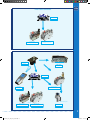
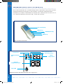
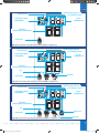
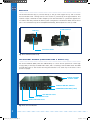
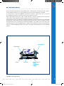
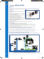
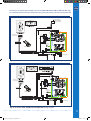
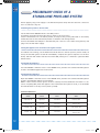
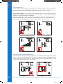
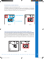
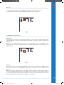
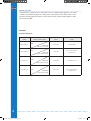
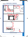
PROFLAME GT-GTM-GTMF-GTMFS
9.955.093 00 (09)
Subject to change without notice
ADVANCED REMOTE CONTROL SYSTEMS
w
0_I00_gtmf_cat_only 0-1 1
w
w
.
s
i
t
g
r
o
u
p
.
i
t
1/0/00 1.0.
•
The Standalone Proflame is an automatic ignition gas control system that
includes an user selectable intermittent or standing pilot.
Features include: twin safety system with true flame detection for enhanced
safety and reliability, On/Off, Manual Hi/Low, and Remote modulation valve
configurations, integrated for use with the Proflame Remote Control GT, GTM,
GTMF, GTMS and GTMFS families, operable from a wall switch or a remote control,
a low power consumption design provides a choice for AC power, Battery power or
AC power with Battery back up.
The 880 Proflame Control provides basic ON/OFF operation of gas flow to the pilot
and main burners of the heating appliance.
The 886 Proflame Control has the same functions as the 880 control except that it
includes HI/LO knob for manual flame height adjustment.
The Proflame controls are designed to be used with either LPG or Natural Gas and
can be converted by use of an OEM supplied conversion kit.
The 880 valves can also be upgraded to 886 configurations by installing OEM
supplied conversion kits.
•
The Proflame GTMS is a modular remote control system that directs multiple
functions of modern hearth appliances. The GTMS is configured to control the
on/off and flame height operation of the main burner, provides for thermostatic
control of the appliance and Split Flow dual burner control. The control features
an advanced Smart thermostat which automatically modulates the flame height
optimizing room temperature management.
The Proflame GTMS system is specifically developed to be used together with the
Proflame 885 valve, Digital Fireplace Control (DFC) board and provides battery back
up in the event of line power loss.
•
The Proflame GTMFS is a modular remote control system that directs multiple
functions of modern hearth appliances. The GTMFS is configured to control the
on/off and flame height operation of the main burner and provides for thermostatic
control of the appliance. Additional features include; fan speed control through
6 levels, a remotely actuated 120/60Hz power outlet and Split Flow dual burner
control. Comfort control is advanced by the Smart thermostat feature which
automatically modulates the flame height optimizing the temperature management
and the room ambience.
The Proflame GTMFS system is specifically developed to be used together with the
Proflame 885 valve, Digital Fireplace Control (DFC) board and provides battery back
up in the event of line power loss.
0_I00_gtmf_cat_only 0- 1/0/00 1.0.
PROFLAME Standalone SPLIT FLOW
GTMF & GTMFS ONLY
GTMFS ONLY
PROFLAME
FMC
IGNITION BOARD
SPLIT FLOW
PROFLAME
Receiver
880 PROFLAME
Combination Gas Control
GTMF & GTMFS ONLY
GTMFS ONLY
PR
OF
FM LAM
C E
IGNITION BOARD
PR
O
Re FLA
ce M
ive E
r
82
0
Co NO
m VA
bin m
ati illi
on vo
Ga lt H
s C I-L
on O W
tro
l
885 PROFLAME
Combination Gas Control
PROFLAME
FMC
IGNITION BOARD
PROFLAME
Receiver
885 PROFLAME
Combination Gas Control
880 PROFLAME
820
millivolt HI-LOW
Combination
Gas NOVA
Control
PROFLAME
Combination Gas Control
Transmitter
886 PROFLAME
Combination Gas Control
885 PROFLAME
Combination Gas Control
PROFLAME
Transmitter
829 NOVA millivolt
Combination Gas Control
SPLIT FLOW
820 NOVA millivolt HI-LOW
Combination Gas Control
829 NOVA millivolt
Combination Gas Control
OF
FM LAM
C E
GTMF & GTMFS ONLY
PR
GTMFS
ONLY
PROFLAME
PR
O
Re FLA
ce M
ive E
r
FMC
SPLIT FLOW
PRO
GTMFS ONLY
FLA
FM ME
C
ME
PROFLA
FMC
PROFLAME
82
FMCCo 9 NOVA millivolPtR
mbination
OFL
Gas Cont
A
Rero
celi ME
ver
ME
PROFLA
r
Receive
Combination Gas Control
Receiver
ME
PROFLA r
itte
885 PROFLAME
Transm
885 PROFLAME
Combination Gas Control
PROFLAME
ME
886 PROFLAME
PROFLA Combination Gas Control
Transmitter
C
FM
Combination Gas Control
SPLIT FLOW
PROFLAME
FMC
PROFLAME
Receiver
PROFLAME
Receiver
PROFLAME
Transmitter
PROFLAME
Transmitter
PROFLAME
82
0
Co NO
m VA
bin m
at illi
ion vo
Ga lt H
s C I-L
on O W
tro
l
PR
886 PROFLAME
OF millivolt
886 PROFLAME
820 NOVA millivolt HI-LOW
Transmitter
829 NOVA
Combination Gas Control
LA
FMControl
Combination
Gas
Combination Gas Control
M
E
Combination
M
C GasEControl
PROFLAME
GTMF & GTMFS
ONLY
PROFLA
r
e
iv
FMC
ece
829
R
GTMFS
ONLY
Com
N
PR
bin OVA
O
atio mPilR
Re FLA
n GTr liOvoF l
ce M
asanC LtA
ive E
somnt M
E
r
ittrol
PROFLAME
IGNITION BOARD
er
PROFLAME
820
NOVA
829 NOVA millivolt
880 PROFLAME
FMC millivolt HI-LOW
GTMF only
E
M
LA
82
Receiver
ROF
Combination
Gas Control
Combination
0 Gas Control
Combination Gas Control
ill
820 NOVA millivolt HI-LOW
r ivolt l
PRP NNOVA
m
te
A
829
NOVA
millivolt
it
V
Co NO
O
sm
820
millivolt
HI-LOW
9OaFn
829 NOVA millivolt
Tr8a2Tr
Contro
m VA
Combination Gas Control
Gas Control
on Gas Gas ControlCombinationGTMS
b
n inaLti
AM
Combination
m
& GTMFS
ONLY Gas Control
Combination
Combsm
829 NOVA millivolt inati illi
GT only
E
W
i
LO
It
on vo
H
t
lt
er
Combination Gas Control
millivo
Ga lt H
ntrol
PROFLAME
o
0 NOVA n G880
C
2
s
8
I
a
s
PROFLAME
885 PROFLAME Co LO
atio
Receiver SPLIT FLOW
nt W Combin Combination Gas Control
Combination Gas Control
PROFLAME
ro
l
Transmitter
GTMF & GTMFS ONLY
livolt HI-LOW
Gas Control
Co 829
m
bin NO
ati VA
on mi
Ga llivo
s C lt
on
tro
PROFLAME
IGNITION
BOARD880 PROFLAME
PROFLAME
FMC
PROFLAME
Combination
Gas
Control
FMC
Transmitter
PROFLAME
880 PROFLAME
880 PROFLAME
Receiver
885 PROFLAME
Combination Gas Control
Combination
Gas
Control
PROFLAME
PRO
Tra FLAM
ns
E
829 NOVA millivoltmitte
r
Combination Gas Control
SPLIT FLOW
PR
PROFLAME
OF
L
Transmitter
GTMF & GTMFS ONLY FM AME
C
GTMFS ONLY
PR
O
Re FLA
ce M
IGNITION BOARDiver E
PROFLAME
GTMF & GTMFS ONLY
Receiver
GTMFS ONLY
IGNITION BOARD
PROFLAME
Receiver
PROFLAME
FMC
IGNITION BOARD
Co 82
m 9N
bin O
at VA
ion m
Ga illivo
s C lt
on
tro
l
GTMF & GTMFS ONLY
SPLIT FLOW
PR
Tra OF
ns LAM
m
itt E
er
PROFLAME
Transmitter
VA
m
atio illivol
n G t HIas C LOW
ont
rol
Combination Gas Control
886 PROFLAME
Combination Gas Control
l
PROFLAM
E
PROFLAMETransmitter
Receiver
820 NOVA millivolt HI-LOW
Combination Gas Control
PROFLAME
Receiver 829 NOVA millivolt
PROFLAM
E
FMC
PROFLAM
E
820 NOVARe
millivolt
ceiver HI-LOW
Combination
Gas
Control
PROFLAME
FMC
820 NOVA
millivolt HI
-LOW
Combinatio
n Gas Cont
rol
PROFLAME
Transmitter
PROFLAME
GTMF & GTMFS
ONLY
FMC
GTMFS ONLY
886 PROFLAME
Combination Gas Control
880 PROFLAME
PR
Combination
Gas Control
Tra OFL
ns AM
m
itt E
er
Co 829
m
bin NO
ati VA
on mi
Ga llivo
s C lt
on
tro
SPLIT FLOW
820 NOVA millivolt HI-LOW
l
885 PROFLAME
886 PROFLAME
Combination Gas Control
Combination Gas Control
Combination Gas Control
Co 829
m
bin NO
ati VA
on mi
Ga llivo
s C lt
886 PROFLAME
on
Combination Gas Control
tro
l
8200-
NOVA millivolt
HI-LOW
0_I00_gtmf_cat_only
Combination Gas Control
W
olt HI-LO
ol
VA milliv NOVA
820 NO tio829
as Contrmillivolt
G
n
ombina
GTMFS ONLY
829 NOVA millivolt
Combination GasPROFLAME
Control
Transmitter
IGNITION BOARD
PROFLAME
FMC
olt
VA milliv
829 NO Gas Control
tion
a
in
b
m
Co
880 PROFLAME
Combination Gas Control
PROFLAME
Receiver 1/0/00 1.10.
S
GTM
G
IGNI
8
Comb
8
Comb
main characteristics
FeatureIcon
GT
•
•
•
•
•
Room Temperature Display
Child Lock
Low Battery
On/Off Thermostat
Flame On/Off only
•
•
•
•
•
•
•
•
•
•
•
•
•
•
•
•
•
•
Flame On/Off & Modulation (6 Levels)
•
Smart Thermostat
Fan Speed Control (6 Levels)
On/Off Auxiliary Outlet (120V)
PROFLAME
GTM GTMS GTMF GTMFS
Constant Outlet (120V)
Split flow
•
•
•
•
•
•
•
•
•
•
•
•
•
•
•
•
•
•
•
•
•
(•) Indicates included Features
technical data
remote control
Supply voltage: Ambient temperature ratings:
Radio frequency:
4.5 V (three 1.5 V AAA batteries)
0 to 50 °C (32 to 122 °F)
315 MHz
receiver
Supply voltage: Ambient temperature ratings:
Radio frequency:
6.0 V (four 1.5 V AA batteries)
0 to 60 °C (32 to 140 °F)
315 MHz
0_I00_gtmf_cat_only 0- 1/0/00 1.10.
fan control module (Proflame GTMF & GTMFS only)
Supply voltage/frequency: Ambient temperature ratings:
Three wires bus: Output voltage/frequency/current: Aux switched output: Fan speed output: 120 V / 60 Hz
0 to 60 °C (32 to 140 °F)
two wires to provide DC voltage to the receiver;
one wire gives uni-directionally signal from the receiver
120 V / 60 Hz / 5 A
120 V / 60 Hz / 2 A
120 V / 60 Hz / 1 A
DFC control board
Supply voltage
Ambient temperature ratings
Spark voltage
Spark energy
Spark frequency
Tested gas types
Pilot ignition source
DC IN: 7Vdc - 200mA max (Class 2 power supply)
BB IN: 6Vdc - 200mA max (four 1.5V size AA batteries)
-18 to +80 °C (0 to +176 °F)
>15kV
>0,7mJ
1Hz
the system has been tested both for NG, and LPG gas types/mixtures
Intermittent/Continuous
system COMPONENTS
The Standalone System consists of four main elements:
1. Proflame Digital Fireplace Control (DFC)
2. Proflame 880, or 886 families of gas valves
3. Pilot assembly
4. Proflame DFC wiring harness to connect the DFC to the gas valve, and to the pilot burner
The GTMS System consists of eight main elements:
1. Proflame GT Series Transmitter
2. Proflame GT Series Receiver
3. Proflame Digital Fireplace Control (DFC)
4. Proflame Gas Valve 885 family (also the 880, 886 families are compatible)
5. Pilot assembly
6. Split Flow Control (optional)
7. Proflame GT Series wiring harness to connect the Receiver to the DFC wirings, to the Gas valve
stepper motor, and to the Split Flow Control
8. Proflame DFC wiring harness to connect the DFC to the gas valve, and to the pilot burner
The GTMFS System consists of nine elements:
1. Proflame GT Series Transmitter
2. Proflame GT Series Receiver
3. Proflame Fan Control Module (FCM)
4. Proflame Digital Fireplace Control (DFC)
5. Proflame Gas Valve 885 family (also the 880, 886 families are compatible)
6. Pilot assembly
7. Split Flow Control (optional)
8. Proflame GT Series wiring harness to connect the Receiver to the FCM, to the DFC wirings, to
the Gas valve stepper motor, and to the Split Flow Control
9. Proflame DFC wiring harness to connect the DFC to the gas valve, and to the pilot burner.
0_I00_gtmf_cat_only 0- 1/0/00 1.10.
transmitter (remote Control with LCD Display)
The Proflame Transmitter uses a streamline design with a simple button layout and informative
LCD displaywith blue back light (Fig.1). The transmitter is powered by 3 AAA type batteries.
A Mode key is provided to index between the features and a Thermostat key Is used to turn on/
off or index through thermostat functions (Fig. 1 & 2A & 2B & 2C & 2D).
Blue LCD display
ON/OFF Key
THERMOSTAT Key
Up/Down Arrow Key
MODE Key
Fig. 1: Proflame Transmitter.
Transmission
Thermostat OFF/
ON
Child safety lock-out
Low battery alarm
Room
Temperature
Set Point
Temperature/State
Flame ON
Fig. 2A: Transmitter LCD display (Proflame GT configuration)
0_I00_gtmf_cat_only 0- 1/0/00 1.10.
Transmission
Child safety lock-out
Low battery alarm
Thermostat OFF/
ON/SMART
Room
Temperature
Set Point
Temperature/Level/State
Flame ON
Fig. 2B: Transmitter LCD display (Proflame GTM configuration)
Transmission
Child safety lock-out
Low battery alarm
Thermostat OFF/
ON/SMART
Room
Temperature
Set Point
Temperature/Level/State
Fan
Flame ON
Aux ON
Fig. 2C: Transmitter LCD display (Proflame GTMF configuration)
Transmission
Thermostat OFF/
ON/SMART
Child safety lock-out
Low battery alarm
Room
Temperature
Set Point
Temperature/Level/State
Fan
Flame ON
Fig. 2D: Transmitter LCD display (Proflame GTMFS configuration)
Split flow
Aux ON
0_I00_gtmf_cat_only 0- 1/0/00 1.10.
receiver
The Proflame Receiver (Fig. 3) connects directly to the gas valve stepper motor, and to the Fan
Control Module with a wiring harness. The receiver is powered by 4 AA type batteries. The
receiver accepts commands via radio frequency from the Transmitter to operate the appliance in
accordance with the particular Proflame system configuration. The Receiver slider switch can be
set to one of these three positions: ON (Manual Override), Remote (Remote control) or OFF.
12 PIN terminal
PRG Key
3 Positions Slider
Fig. 3: Proflame Receiver body.
Fan Control Module (Proflame GTMF & GTMFS only)
Fan Control Module (FCM) offers the added ability to control the fan speed from off through
six (6) speeds, a remotely actuated 120V outlet, and a constantly powered 120V outlet. The FCM
provides DC power to the receiver allowing the batteries to be used only in the event of line
power loss (Fig.4).
Mains voltage
supply cord
module on/off switch
communication bus (3 pin)
AUX outlet plug
FAN outlet plug
Mains voltage plug
Fig. 4: Fan Control Module.
0_I00_gtmf_cat_only 0- 1/0/00 1.1.00
DFC control board
The Proflame Digital Fireplace Control (DFC) board is a device that allows the automatic ignition
and pilot flame supervision, to command the functions of a hearth appliance, see fig.4A.
It’s configured to control the ON/OFF main burner operation, giving the choice of both IPI
(intermittent pilot ignition), and CPI (continuous pilot ignition) modes.
The Proflame DFC board controls and connects directly to the pilot assembly and an automatic
valve of the Proflame 880, 886 and 885 families using low electric power.
The DFC Board can be powered by an AC/DC wall adaptor and battery pack for back up (Stand
Alone System). When used with the Proflame Remote System, with or without a split flow valve,
the DFC Board can be powered by an AC/DC wall adaptor via specific wire harness using the
receiver batteries for back up (GTM System). Additionally, the DFC Board can be powered by the
Fan Control Module (FCM) via specific wire harness using the receiver batteries for back up (GTMF
System).
DIAGNOSTIC
IONIZATION
SPARK
GROUND
MAIN WIRING
VALVE,
COMMAND,
POWER
Fig. 4A: Proflame DFC Board.
0_I00_gtmf_cat_only 0- 1/0/00 1.1.0
installation
Receiver
The receiver can be placed inside a standard junction type wall box or a low temperature area of
the appliance.
Wall Mounting
1. Connect the wiring harness to the back of the
receiver.
2. Install the receiver in the Junction box using the
existing J box screws. (Fig. 5)
3. Insert the 4 AA type batteries in the battery
compartment with the correct polarity.
4. Place the slider into the cover plate.
5. Put the receiver switch in the “OFF” position.
6. Make sure the receiver and cover plate words
“ON”and “UP” are on the same side.
7. Align the slider with the switch on the receiver and couple the switch into the slider.
8. Align the screw holes.
9. Using the two (2) screws provided secure the cover plate to the receiver.
Fig. 5
Hearth Mounting
1. Connect the wiring harness to the back of the receiver.
2. Install the 4 AA type batteries in the battery compartment with the correct polarity.
3. Make sure the receiver and cover plate words “ON” and “UP” are on the same side.
4. Place the slider into the cover plate.
5. Align the slider with the switch on the receiver and couple the switch into the slider.
6. Using the two (2) screws provided secure the cover plate to the receiver.
Fan Control module (Proflame GTMF & GTMFS only), and DFC control board
The FCM must be placed in a low temperature area of the appliance.
The Proflame DFC board should be placed in a low temperature area of the appliance.
Connecting to the 880/886 Gas Valve and DFC control board
The electrical connections must be in accordance to Fig. 6A.
ON / OFF
CPI / IPI MODE
Orange
ON/OFF
Green
IPI/CPI
Battery
Holder
Red
Black
880/886 Proflame
VALVE
BATTERY
120 Vac INPUT
7 Vdc STABILIZED
SUPPLY OUTPUT
Chassis
connection
GROUND
DFC
DC SUPPLY
Fig. 6A: Proflame Standalone & 880/886 PROFLAME wiring diagram.
10
0_I00_gtmf_cat_only 0-10 10
1/0/00 1.1.0
Connecting to the 885 Gas Valve and DFC control board (Proflame GTM & GTMS & GTMF & GTMFS only)
The electrical connections must be in accordance to Fig. 6B ( GTM & GTMS) or 6C (GTMF & GTMFS).
120 Vac INPUT
7 Vdc STABILIZED
SUPPLY OUTPUT
REMOTE
REMOTE
MOTOR
DC SUPPLY
Receiver 14
Pin Connector
Orange
Pilot
Green
Pink
Blue
GTMS only
Split Flow
RECEIVER
885 PROFLAME
SPLIT FLOW
Chassis
connection
GROUND
TPTH
TH
ON / OFF
Remote control
DC SUPPLY
DFC SUPPLY
IPI/CPI
CPI / IPI MODE
Fig. 6B: Proflame GTM & GTMS & 885 PROFLAME wiring diagram.
REMOTE
120V OUT
REMOTE
MOTOR
FCM-COM
Receiver 14
Pin Connector
Orange
Pilot
Green
Pink
Blue
GTMFS only
Split Flow
RECEIVER
885 PROFLAME
SPLIT FLOW
TH
GROUND
TPTH
ON / OFF
Chassis
connection
Remote control
DFC SUPPLY
DFC SUPPLY
IPI/CPI
CPI / IPI MODE
Fig. 6C: Proflame GTMF & GTMFS & 885 PROFLAME wiring diagram.
11
0_I00_gtmf_cat_only 0-11 11
1/0/00 1.1.10
Preliminary check of a
Standalone Proflame system
Before applying any power supply to the DFC board please verify that the electrical connections
are in accordance to Fig. 6A
Initializing the System for the first time
Set the main burner ON/OFF switch to the OFF position.
If installed, set the pilot flame mode selector switch to the IPI position.
Install 4 AA batteries into the battery holder, and respect the polarity indicated on the battery
holder silkscreen. Connect the battery holder to the DFC’s main wiring harness.
Connect the AC/DC wall adapter to the DFC’s DC-jack connector on the main wiring harness, and
plug it into the wall mains supply.
Setting the Appliance into Continuous Pilot ignition mode
If installed on the wirings, set the IPI/CPI Pilot Mode Switch to the CPI position (switch closed). At
that point the DFC ignition board will immediately complete the ignition sequence for the Pilot
Flame, and then will remain with the Pilot Flame ON, waiting for a command to ignite the Main
Burner Flame.
Turning ON the Appliance
Close the ON/OFF command contact on the ON/OFF wires, and this will command the DFC ignition
board to Turn-ON the appliance’s main burner.
Turning OFF the Appliance
Open the ON/OFF command contact on the ON/OFF wires, and this will command the DFC ignition
board to Turn-OFF the appliance’s main burner.
NOTE: if the Continuous Pilot ignition mode is selected, the Pilot ON Flame will remain. To also
turn it completely OFF, switch the appliance into Intermittent Pilot ignition mode, so set the IPI/CPI
Pilot Mode Switch to the IPI position (switch opened).
Command definitions
Pilot IPI / CPI
switch
Main Turn ON
switch
Command reference
name
Commanded Fireplace
State
Opened, IPI
Opened
Turn-OFF
Flames OFF
Opened, IPI
Closed
Turn-ON
Pilot + Main burner
flames ON
Closed, CPI
Opened
Pilot-ON
Pilot flame ON
Closed, CPI
Closed
Turn-ON
Pilot + Main burner
flames ON
12
0_I00_gtmf_cat_only 0-1 1
1/0/00 1.1.11
OPERATING PROCEDURE for a
remote control system
Initializing the System for the first time
Install the 4 AA batteries into the receiver battery bay. Note the polarity of the battery and insert
into the battery bay as indicated on the Battery cover (+/-). Place the 3 position slider switch in the
“REMOTE” position. (fig. 3) Insert the end of the paper clip or similar object into the hole marked
“PRG” on the Receiver front cover (fig 3). The Receiver will “beep” three (3) times to indicate that
it is ready to synchronize with a Transmitter. Install the 3 AAA type batteries in the Transmitter
battery bay, located on the base of the Transmitter. With the batteries already installed in the
Transmitter, push the ON button. The Receiver will “beep” four times to indicate the Transmitter’s
command is accepted.
The system is now initialized.
Temperature indication Display
With the system in
the “OFF” position,
press the Thermostat
Key and the Mode
Key at the same
time. Look at the
LCD screen on the
Transmitter to verify that a °C or °F
is visible to the
right of the Room
Temperature display.
(Fig. 7)
Fig. 7: Remote Control display in Farenheit and Celsius.
Setting the Appliance into Continuous Pilot ignition mode
If installed on the wirings, set the IPI/CPI Pilot Mode Switch
to the CPI position (switch closed). At that point the DFC ignition board will immediately complete the ignition sequence
for the Pilot Flame, and then will remain with the Pilot Flame
ON, waiting for a command to ignite the Main Burner Flame.
Turning ON the Appliance
Press the ON/OFF Key on the Transmitter. The Transmitter
display will show all active Icons on the screen. At the same
time the Receiver will command the DFC board to start the
ignition process. Once the pilot flame is proven the DFC
board will open the main valve outlet and the appliance
main burner will ignite. A single “beep” from the Receiver
will confirm reception of the command.
Fig. 8: Remote Control display.
Turning OFF the Appliance
Press the ON/OFF Key on the Transmitter. The Transmitter LCD display will only show the room
temperature and Icon (Fig. 8). At the same time the Receiver disconnects will command the DFC
board to turn off the burner. Depending on the system model (IPI or CPI) the pilot may shut off
(IPI) or remain lit (CPI) and the appliance burner turns OFF. A single “beep” from the Receiver confirms reception of the command.
NOTE: if the Continuous Pilot ignition mode is selected, the Pilot ON Flame will remain. To also
turn it completely OFF, switch the appliance into Intermittent Pilot ignition mode, so set the IPI/CPI
Pilot Mode Switch to the IPI position (switch opened).
0_I00_gtmf_cat_only 0-1 1
13
1/0/00 1.1.1
Flame Height Control
Proflame GT: with the system on, and the flame present in the appliance, pressing the Down
Arrow Key (Fig. 1) will turn OFF the flame while the remote system is still on. If the Up Urrow Key
is pressed while in the above described state the flame will come on. ( Fig. 9A & 9D)
Proflame GTM & GTMF: has six (6) flame levels. With the system on, and the flame level at the
maximum in the appliance, pressing the Down Arrow Key (Fig. 1) once will reduce the flame
height by one step until the flame is turned OFF.
The Up Arrow Key will increase the flame height each time it is pressed. If the Up Arrow Key is
pressed while the system is on but the flame is off, the flame will come on in the high position.
( Fig. 9A & 9B & 9C& 9D ) A single “beep” will confirm reception of the command.
Fig. 8:
Fig. 9A: Flame Off
Fig. 9:
Fig. 9C: Flame level 5
Fig. 9B: Flame Level 1
Fig. 9D: Flame Level Maximum
Split flow function ( GTMS & GTMFS only )
The secondary burner is controlled by the split Flow. To activate this function use the Mode Key
(Fig. 1) to index to the SPLIT FLOW icon (Fig. 9E & 9F). Pressing the Up Arrow Key will activate
the secondary burner. Pressing the Down Arrow Key will turn the secondary burner OFF. A single
“beep” will confirm the reception of the command.
14
0_I00_gtmf_cat_only 0-1 1
Fig. 9:
Fig. 9E
Fig. 9F
1/0/00 1.1.
Room Thermostat ( Transmitter Operation)
The Remote Control can operate as a room thermostat. The thermostat can be set to a desired
temperature to control the comfort level in a room.
To activate this function, press the Thermostat Key (Fig. 1). The Lcd display on the Transmitter
will change to show that the room thermostat is “ON” and the set temperature is now displayed
(Fig. 10). To adjust the set temperature, press the Up or Down Arrow Keys until the desired set temperature is displayed on the LCD screen of the Transmitter (Fig. 11).
ROOM TEMPERATURE
SET TEMPERATURE
Fig. 10
Fig. 11
Smart Thermostat (Transmitter Operation) (Proflame GTM & GTMF & GTMFS only)
The Smart Thermostat function adjusts the flame height in accordance to the difference between
the set point temperature and the actual room temperatures. As the room temperature gets
closer to the set point the Smart Function will modulate the flame down. To activate this
function, press the Thermostat Key (Fig. 1) until the word "SMART" appears to the right of the
temperature bulb graphic (Fig. 12). To adjust the set temperature, press the Up or Down Arrow
Keys until the desidered set temperature is displayed on the LCD screen of the Transmitter (Fig.
13).
Fig. 12: Smart flame function
Fig. 13
15
0_I00_gtmf_cat_only 0-1 1
1/0/00 1.1.
Fan Speed Control (Proflame GTMF & GTMFS only)
If the appliance is equipped with a hot air circulating fan, the speed of the fan can be controlled
by the Proflame system. The fan speed can be adjusted through six (6) speeds. To activate this function use the Mode Key (fig.1) to index to the fan control icon (Fig. 14). Use the Up/Down Arrow
Keys (fig.1) to turn on, off or adjust the fan speed (fig. 15). A single “beep” will confirm reception
of the command.
Fig. 14
Fig. 15
Remote Actuated 120V Auxiliary Outlet (Proflame GTMF & GTMFS only)
The auxiliary function controls the AUX power outlet on the Fan Control Module. To activate this
function use the Mode Key (fig. 1) to index to the AUX icon (fig. 16 & 17).
Pressing the Up Arrow Key will activate the outlet. Pressing the Down Arrow Key will turn the
outlet off. A single “beep” will confirm the reception of the command.
Fig. 16
Fig. 17
16
0_I00_gtmf_cat_only 0-1 1
1/0/00 1.1.
Key lock
This function will lock the keys to avoid unsupervised operation.
To activate this function, press the MODE and UP keys at the same time (Fig. 18).
To de-activate this function, press the MODE and UP keys at the same time.
Fig. 18
Low Battery Power detection
Transmitter
The life span of the remote control batteries depends on various factors: quality of the batteries
used, the number of ignitions of the appliance, the number of changes to the room thermostat
set point, etc.
When the transmitter batteries are low, an Icon will appear on the LCD display of the
transmitter (Fig. 19) before all battery power is lost. When the batteries are replaced this Icon
will disappear.
Fig. 19
Receiver
The life span of the receiver batteries depends on various factors: quality of the batteries used,
the number of ignitions of the appliance, the number of changes to the room thermostat set
point, etc.
When the receiver batteries are low, No “beep” will be emitted from the receiver when it
receives an On/Off command from the transmitter. This is an alert for a low battery condition
for the receiver. When the batteries are replaced the “beep” will be emitted from the receiver
when the ON/OFF key is pressed (See Initialization of The System).
17
0_I00_gtmf_cat_only 0-1 1
1/0/00 1.1.
Manual override
If the batteries of the Receiver or Transmitter are low or depleted, the appliance can still be
turned on manually by sliding to the “ON” position the three position slider switch on the
Receiver. This will bypass the remote control feature of the system and the appliance main
burner will Turn-ON.
APPENDIX
Command definitions
Pilot IPI / CPI
switch
Opened, IPI
Opened, IPI
Closed, CPI
Closed, CPI
Position of the
receiver slider switch
“OFF”
“ON”
“OFF”
“ON”
“REMOTE”
and “OFF received”
“REMOTE”
and “ON received”
“REMOTE”
and “OFF received”
“REMOTE”
and “ON received”
Command reference
name
Commanded Fireplace
State
Turn-OFF
Flames OFF
Turn-ON
Pilot + Main burner
flames ON
Pilot-ON
Pilot flame ON
Turn-ON
Pilot + Main burner
flames ON
18
0_I00_gtmf_cat_only 0-1 1
1/0/00 1.1.0
115
REMOTE
dimensional drawings
PRG
70
102
REMOTE
PRG
140
42
115
Hearth mounted
REMOTE
PRG
70
36
37
70
71
Wall mounted
102
70 70
REMOTE
PROFLAME Transmitter
PRG
42
PROFLAME
Receiver
36 36
DFC Control Board
PROFLAME FCM
Dimensions are in millimeters
19
0_I00_gtmf_cat_only 0-1 1
1/0/00 1.1.
SIT La Precisa S.p.A.
Viale dell’Industria 31-33
35129 PADOVA - ITALY
Tel. +39/049/829.31.11, Fax +39/049/807.00.93
www.sitgroup.it - e-mail: [email protected]
0_I00_gtmf_cat_only 0-0 0
1/0/00 1.1.