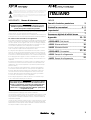
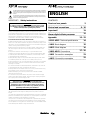
1
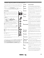
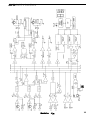
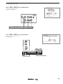
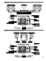
XD13 - AD 52 FRONT PANEL
28 45
MIC
MIC
MIC
1
2
3
LINE /
INSERT
LINE /
INSERT
4
5/6
18
FT. SW.
XLR
1 - GND
2 +
3 -
17
8
9
MIC
7/8
AUX
44
L
INSERT
R
EFF RETN
R
L /
mono
IN
33
R
R
L /
mono
L /
mono
PROCESSOR
37
EFF SEND
11/12
9/10
OUT
R
SEND
L /
mono
LINE/
RETN
7
GAIN
CL
4
1
2
15
15
2
2
15
15
2
2
15
15
4
6
8
8
15
15
2
2
15
15
4
6
8
5
PAN
L
15
2
2
15
15
2
2
15
15
4
6
8
12
8
2
13
8
10
6
0
10
2
EFF
15
2
2
15
15
2
2
15
15
4
6
19
8
PROGRAM
ON
10
+ 9
+ 6
+ 6
+ 3
+
+ 3
dB 0
0
dB 0
PAN
1
L
14
R
2
3
BAL
4
L
BAL
R
23
5
6
24
8
9
10
6
12
12
0
10 TO AUX
2
15
18
24
RIGHT
LEVEL
6
36
8
10
12
L
R
MASTER
L
EFF
6
6
0
0
40
50
6
6
6
18
18
18
30
30
30
30
40
50
40
50
40
50
40
50
30
30
40
50
40
50
26
31
EFF
BAL
32
0
10
4
6
0
10
8
TAPE
IN VOL
39
40
8
R
0
6
30
PHONES VOL
6
18
R
6
2
0
6
L
4
2
BAL
29
EFF
8
24
LEFT
LEVEL
10
2
11
EFF
RETN
38
21
ON
6
18
8
10
21
6
2
EFF
SEND
4
0
30
6
0
6
15
4
8
9
0
6
10
6
6
18
0
AUX
MASTER
3
0
6
6
9
6
18
4
8
8
TONE 0
25
R
7
10
6
18
2
AUX 0
4
8
L
0
3
15
PARAMETER
8
0
+ 9
22
10
6
27
CL
4
2
EFF
20
21
8
4
6
2
8
2
4
2
8
AUX 0
10
4
15
8
LF
8
AUX 0
2
8
MF
8
8
LF
2
8
HF
Montarbo
8
10
8
8
MF
6
0
15
6
M
R
6
11
10
2
EFF
2
8
8
M
2
DIGITAL PROCESSOR
CL
4
2
8
10
HF
8
4
10
0
2
AUX 0
6
2
EFF
2
GAIN
6
2
8
2
8
10
4
15
8
LF
2
15
8
MF
8
AUX 0
2
8
HF
8
2
CL
4
10
8
10
8
MF
LF
4
6
10
2
GAIN
CL
4
2
8
8
3
GAIN
6
2
HF
2
34
16
200
OUT
600
47
L
TAPE
IN
TAPE
OUT
L
46
R
R
35
XD13 REAR PANEL
41
48
MOD.
XD 13
MADE IN ITALY
49
42
RIGHT
220V-240V
50-60Hz
FUSE T 0,5A
POWER
I
BY
ELETTRONICA
R
Montarbo
OUTPUTS
LEFT
1 - GND
2 - signal
3 - GND
L
S.R.L.
0
SERIAL N.
Montarbo
AD 52 REAR PANEL
41
43
SPEAKER OUTPUTS
FUSE
F 5A
180W
AVIS !
CAUTION !
FUSE
F 5A
POUR PREVENIR TOUT RISQUE DE CHOC
ELECTRIQUE, NE PAS OUVRIR
TO PREVENT ELECTRICAL SHOCK,
DO NOT REMOVE COVERS
U S
POUR PREVENIR TOUT RISQUE DE FEU REPLACER
^
TOUJOURS UN FUSIBLE DE MEME CARACTERISTIQUES
^
CET APPAREIL DOIT ETRE RELIE` A LA TERRE
TO PREVENT RISK OF FIRE ALWAYS REPLACE
FUSES WITH SAME TYPE AND RATINGS
THIS APPARATUS MUST BE EARTHED
E
F
MIN LOAD 4
180W
E
U S
MIN LOAD 4
F
POWER
I
STEREO POWERED MIXER
MOD.
AD 52
MADE IN ITALY
SERIAL N.
0
RIGHT
LEFT
220V-240V
50-60Hz
1 - gnd
2 - signal
3 - n.c.
FUSE T 3,15A
48
49
Montarbo
43
Montarbo
2
Il lampo con la freccia inserito in un triangolo equilatero avvisa l'utilizzatore circa la
presenza di 'tensione pericolosa', senza isolamento, all'interno dell'apparecchio che
potrebbe essere sufficientemente alta da generare il rischio di scossa elettrica.
ITALIANO
Il punto esclamativo inserito in un triangolo equilatero avvisa l'utilizzatore circa la
presenza di importanti istruzioni per l'utilizzo e per la manutenzione nella documentazione che accompagna il prodotto.
IMPORTANTE ! Norme di sicurezza
INDICE
ATTENZIONE !
Nell'interesse della propria e della altrui sicurezza, e per non
invalidare la garanzia, si raccomanda una attenta lettura di
questa sezione prima di adoperare il prodotto.
- Questo apparecchio è stato progettato e costruito per venire utilizzato
come mixer/mixer amplificato nel contesto tipico di un sistema di amplificazione sonora, e/o di un sistema di registrazione sonora.
L'utilizzo per scopi diversi da questi non è contemplato dal costruttore, ed
avviene pertanto sotto la diretta responsabilità dell'utilizzatore/installatore.
Per evitare il rischio di incendio e/o di folgorazione:
• Non esporre il prodotto alla pioggia non utilizzarlo in presenza di elevata
umidità o vicino all'acqua. Non lasciare penetrare all'interno dell'apparecchio alcun liquido, né alcun oggetto solido. In caso ciò avvenga, scollegare
immediatamente l'apparecchio dalla rete elettrica e rivolgersi ad un servizio di assistenza qualificato prima di adoperarlo nuovamente.
• Prima di collegare l'apparecchio alla rete elettrica assicurarsi che la tensione corrisponda a quella indicata sull'apparecchio stesso.
• Collegare questo apparecchio esclusivamente ad una presa di corrente
dotata di contatto di terra rispondente alle norme di sicurezza vigenti tramite il cavo di alimentazione in dotazione. Nel caso in cui il cavo necessiti
di sostituzione, utilizzare esclusivamente un cavo di identiche caratteristiche.
• Non appoggiare alcun oggetto sul cavo di alimentazione. Non posarlo
dove possa costituire intralcio e causare inciampo. Non schiacciarlo e non
calpestarlo.
• Durante il funzionamento non coprite il mixer e non tenetelo dentro a
contenitori che possano ostruire la circolazione d'aria (necessaria al raffreddamento). Non ostruire le aperture o le prese d'aria presenti sull'apparecchio (AD52).
• In caso di sostituzione del fusibile esterno, utilizzare esclusivamente
un fusibile di caratteristiche identiche, come riportato sull'apparecchio.
• Prima di effettuare qualsiasi operazione di collegamento, assicurarsi
che l'interruttore di accensione dell'apparecchio sia in posizione 'Off'.
• Prima di effettuare qualsiasi spostamento del prodotto già installato
o in funzione, rimuovere tutti i cavi di collegamento.
• Per scollegare l'apparecchio dalla rete elettrica, non tirare mai lungo
il cavo, ma afferrarlo sempre per il connettore.
2
Pannello
frontale e posteriore
__________________________________________
4-5
Controlli
e connessioni
__________________________________________
6
Importante
!
__________________________________________
7
Processore
digitale di effetti stereo
__________________________________________
13 - 22
Appendix:
__________________________________________
14
◗__________________________________________
XD13 - AD 52 Dati tecnici
15
◗ XD13 Schema a blocchi
__________________________________________
16
◗ AD 52 Schema a blocchi
__________________________________________
17 - 20
◗__________________________________________
XD13 - AD 52 Connessioni
21
◗ XD13 Esempi di collegamento
__________________________________________
22
◗ AD52 Esempi di collegamento
__________________________________________
ATTENZIONE !
Questo apparecchio non contiene parti interne destinate all'intervento diretto da parte dell'utilizzatore. Per evitare il rischio di
incendio e/o folgorazione, non aprirlo. Per qualsiasi intervento
di manutenzione o riparazione, rivolgersi alla Elettronica
Montarbo srl e/o a personale altamente qualificato specificamente segnalato da questa.
- Nel predisporre l'apparecchio all'utilizzo, assicurarsi che la forma e la portata della superficie di appoggio siano idonee a sostenerlo.
- Per evitare urti riservate come luogo per l'istallazione del prodotto un'area
protetta inaccessibile a personale non qualificato. Qualora l'apparecchio
venga utilizzato in presenza di bambini e animali, si rende necessaria una
strettissima sorveglianza.
- Questo prodotto utilizzato insieme a cuffie o a casse acustiche è in grado
di generare pressioni acustiche molto elevate, pericolose per la salute del
sistema uditivo. Evitarne quindi l'utilizzo ad elevati o fastidiosi livelli acustici.
Non esporre i bambini a forti sorgenti sonore.
Montarbo
3
CONTROLLI E CONNESSIONI
CANALE D'INGRESSO MONO
CANALE D'INGRESSO STEREO
1 ➤ GAIN: controlla il guadagno dello stadio di ingresso, permettendo il collegamento di sorgenti sia microfoniche che di linea aventi
segnali di uscita estremamente variabili. Come regola generale, al
fine di contenere al minimo il rumore, consigliamo di regolare il
GAIN al massimo livello possibile, evitando però che l'indicatore di
picco (CL) si illumini.
10 ➤ GAIN: come nel canale mono.
2 ➤ H.F / M.F / L.F. Equalizzazione a 3 bande.
H.F: controlla il livello delle frequenze alte. La frequenza di intervento è 15kHz, l'accentuazione/attenuazione 15dB.
M.F: controlla il livello delle frequenze medie. La frequenza di intervento è 600Hz, l'accentuazione/attenuazione 15dB.
L.F: controlla il livello delle frequenze basse. La frequenza di intervento è 50Hz, l'accentuazione/attenuazione 15dB.
N.B: Girando la manopola in senso orario si ottiene una accentuazione, in senso
antiorario una attenuazione. In posizione centrale la risposta è lineare.
3 ➤ AUX: volume mandata ausiliaria. Permette di regolare la
quantità di segnale del canale nell'uscita ausiliaria (dipende dai
controlli di tono ed è indipendente dal volume del canale).
4 ➤ EFF: volume mandata effetto (dipende dai controlli di tono e
volume del canale). Permette di regolare la quantità di segnale del
canale da inviare sia all'effetto interno che all'eventuale effetto
esterno collegato alle prese send e return.
N.B: Sui canali dove non si vuole avere l'effetto interno e neppure l'eventuale
effetto esterno, girare questa manopola in senso completamente antiorario.
Se si vuole avere solamente l'effetto esterno, disattivare l'effetto interno.
5 ➤ PAN: controllo di panorama. Permette di posizionare il segnale
(del canale) nell’immagine stereo inviandolo in quantità maggiore o
minore alle uscite master L ed R.
6 ➤ VOLUME del canale.
7 ➤ CL: indicatore LED di picco (clipping). Si illumina quando il livello del segnale è prossimo alla distorsione. Il segnale è controllato
contemporaneamente in due punti del canale: • dopo l'amplificatore di ingresso (micro e linea); • dopo l'equalizzatore.
Se il led CL si accende con continuità, è necessario ridurre il guadagno di ingresso (GAIN) o regolare diversamente l'equalizzazione del
canale riducendo l'esaltazione introdotta dai comandi HF, MF, LF.
11 ➤ H.F / M.F / L.F: come nel canale mono.
12 ➤ AUX: come nel canale mono.
.13 ➤ EFF: come nel canale mono.
14 ➤ BAL: controllo bilanciamento. Permette di regolare il livello
relativo destro/sinistro del segnale stereo del canale nelle uscite
master L/R. Se il canale viene usato in mono diventa un comando
PAN (panorama).
15 ➤ VOLUME del canale.
16 ➤ CL: come nel canale mono.
● connessioni:
17 ➤ MIC: per dare ai mixer una maggiore flessibilità di impiego,
anche i canali stereo dispongono di un ingresso microfonico
bilanciato (XLR) mono.
18 ➤ L/R: ingressi linea sbilanciati jack per il collegamento di
strumenti stereo. Per collegamenti 'mono' utilizzare l'ingresso
'L / mono'.
PROCESSORE DIGITALE DI EFFETTI STEREO
Il processore è basato su un DSP a 56 bit con conversione Delta/
Sigma a 18 bit. Offre 16 diversi effetti modificabili in tempo reale di
grande qualità, prestazioni altamente professionali ed una estrema
facilità di utilizzo.
19 ➤ DISPLAY numerico a LED: indica il numero corrispondente al
programma selezionato.
20 ➤ PROGRAM: 2 pulsanti di selezione dei programmi permettono
di selezionare qualsiasi numero della memoria per richiamare uno
dei 16 programmi disponibili.
▼ = tasto di decremento
▲ = tasto di incremento
21 ➤ ON: pulsante per attivare o disattivare l’effetto, con indicatore
LED rosso.
● connessioni:
22 ➤ PARAMETER: controllo che consente di modificare i parametri
dell'effetto scelto mediante i pulsanti di selezione dei programmi.
8 ➤ MIC: ingresso microfonico bilanciato con connettore XLR
(per il collegamento di microfoni).
23 ➤ AUX: mandata ausiliaria. Permette di regolare il livello dell’effetto stereo sull'uscita miscelata aux.
9 ➤ LINE: ingresso linea sbilanciato con connettore jack per il
collegamento di strumenti e sorgenti di segnale ad alto livello.
Incorpora anche la connessione Insert, utilissima per trattare canali
diversi, con apparecchi esterni, singolarmente.
24 ➤ TONE: controllo di tono. Girando la manopola in senso orario
si produce una graduale attenuazione delle alte frequenze (in senso
completamente antiorario la risposta è lineare).
N.B: Non usare contemporaneamente i due ingressi MIC e LINE.
Non collegare strumenti (o altre sorgenti ad alto livello) all'ingresso MIC !
(questo comporterebbe distorsione dovuta al segnale eccessivo).
Non collegare microfoni all'ingresso LINE ! (il segnale sarà di basso livello e
qualità).
25 ➤ BAL: bilanciamento. Permette di regolare il livello relativo
destro/sinistro del segnale stereo dell’effetto da inviare alle uscite
master L ed R.
26 ➤ Controllo di VOLUME.
27 ➤ CL: indicatore LED di picco (clipping). Se lampeggia occasionalmente la condizione di funzionamento è normale, mentre se resta
continuamente acceso è molto vicina alla saturazione ed è necessario diminuire il volume delle mandate effetto sui singoli canali.
● connessioni:
28 ➤ FT/SW: presa jack per footswitch. Consente di disattivare
l'effetto mediante pedale. Ciò è possibile solo quando il relativo
pulsante 'ON' è premuto.
Montarbo
4
CONTROLLI E CONNESSIONI
MANDATE E RITORNI EFFETTI ESTERNI
29 ➤ EFF SEND: controllo di volume per la mandata effetti. Regola il
livello di segnale presente sull'uscita EFF SEND ed è la miscelazione
dei segnali inviati dalle mandate EFF dei singoli canali.
30 ➤ EFF RETN: controllo di volume per il ritorno effetti. Regola il
livello di segnale del ritorno effetto esterno.
31 ➤ EFF TO AUX: regola la quantità di effetto esterno da inviare
all'uscita AUX (monitor).
32 ➤ EFF BAL: bilanciamento stereo dell’effetto esterno. Permette
di regolare il livello relativo destro/sinistro del segnale stereo dell’effetto da inviare alle uscite master L ed R.
● connessioni:
33 ➤ EFF SEND: uscita jack per la mandata effetto esterno.
34 ➤ EFF RETN L/R: 2 ingressi jack per il ritorno stereo dell'effetto.
• Sono utilizzabili anche come 2 ingressi linea extra.
■ Collegare la presa EFF SEND all'ingresso dell'effetto esterno.
■ Collegare le uscite L ed R dell'effetto esterno alle prese EFF RETN
L/R del ritorno effetti stereo.
• Per un effetto mono collegare l'uscita 'only effect'dell'effetto alla presa 'L/mono'
■ Utilizzare i controlli EFF di ogni canale per regolare la quantità di
segnale da inviare all'effetto esterno, il controllo EFF SEND (29) per
regolare la quantità di segnale da inviare all'uscita "eff send", ed i
controlli EFF RETN, EFF TO AUX e EFF BAL (30, 31, 32) per regolare
il ritorno dell'effetto e le quantità dello stesso da inviare all'uscita
"aux" ed ai master "L/R".
• Alla mandata EFF su ogni canale corrisponde anche l'effetto interno.
Per escludere quest'ultimo, disattivarlo mediante il comando 'on'.
N.B: Anzichè dell'uscita EFF SEND, ci si può servire dell'uscita AUX (se non è impegnata per i monitor). In tal caso il segnale dell'effetto esterno sarebbe regolabile
mediante la mandata AUX di ogni canale e quindi totalmente indipendente.
☛ Figura 4 pag. 20
N.B: Se si utilizzano dei connettori jack mono, le prese insert L/R possono fungere
da uscite master L/R. In tal caso le uscite XLR saranno scollegate.
☛ Figura 1A pag. 17
43➤ AD52 SPEAKER OUTPUTS L/R: uscite dei due amplificatori incorporati. L'impedenza minima per ogni amplificatore è di 4 Ω.
■ Collegare 1 o 2 casse acustiche da 8 Ω per ogni uscita. Mai fare
funzionare gli amplificatori interni con carichi inferiori a 4 Ω ciascuno.
N.B: Ogni uscita dispone di prese Jack e XLR (in parallelo), fusibili di protezione,
protezioni elettroniche, relè per inserimento ritardato del carico, autodiagnosi,
ventilazione forzata.
☛ Figura 1B pag. 18
44 ➤ INSERT L/R: prese jack stereo che permettono il collegamento
di apparecchiature ausiliarie esterne (ad esempio equalizzatori grafici, limiter processore audio, ecc…) alle uscite master L/R.
Dipendono dalle regolazioni master L ed R. Per l'inserzione di apparecchiature esterne vedere esempio di collegamento.
☛ Figura 2A pag. 19
Nel mixer XD13 queste prese possono anche essere utilizzate
come normali uscite L/R usando jack mono standard. In questo caso
le uscite XLR sono disattivate.
☛ Figura 2A pag. 19
Nel mixer amplificato AD52 queste prese possono anche essere
utilizzate come uscite preamplificate del mixer per collegare casse
amplificate o amplificatori esterni.
■ Per utilizzare le uscite linea del mixer senza escludere le uscite di
potenza prelevare il segnale dalle due prese insert mediante due jack
stereo, nei quali avrete precedentemente collegato l'anella (RING) con
la punta (TIP) cortocircuitandole, ed inviarlo agli ingressi delle casse
autoamplificate mediante dei jack mono.
☛ Figura 2B pag. 19
• Collegando alle prese insert dei jack mono le uscite degli amplificatori vengono
invece escluse.
35 ➤ L/R MASTER: livelli generali per le uscite master L (sinistra)
ed R (destra).
45 ➤ AUX OUT: uscita ausiliaria (monitor). Può pilotare fino a 10
casse monitor autoamplificate, collegate in parallelo.
■ Collegare l'uscita AUX all'ingresso del monitor amplificato.
Regolare le mandate AUX di ogni canale ed il volume AUX MASTER.
☛ Figura 3 pag. 19
36 ➤ LEFT/RIGHT LEVEL: 2 rampe di LED a 12 segmenti che indicano
il livello delle uscite master L ed R.
N.B: Se non viene utilizzata per i monitor, può servire come mandata effetto
(vedi fig. 4).
SEZIONE MASTER
37 ➤ PROCESSOR: premendo questo pulsante si attiva un processore in grado di modificare il contenuto armonico delle uscite master
L ed R consentendo di ottenere un suono 'corposo' anche a livelli di
ascolto bassi (molto utile quindi per piano-bar e simili).
Nell'XD13, tale processore agisce solamente sulle uscite XLR (e pertanto gli Insert L ed R non ne vengono influenzati) mentre nell'AD52
agisce sulle uscite amplificate.
38 ➤ AUX MASTER: controlla il volume dell'uscita ausiliaria (monitor).
L'uscita master ausiliaria è la miscelazione di tutte le mandate AUX
dei singoli canali.
39 ➤ TAPE IN VOL: volume dell’ingresso Tape.
40 ➤ PHONES VOL: volume dell’uscita in cuffia.
41 ➤ POWER: interruttore generale dell'apparecchio.
● connessioni:
42 ➤ XD13 LEFT/RIGHT OUTPUTS: uscite master L ed R per il collegamento di finali di potenza o casse acustiche amplificate.
■ Collegare le prese di uscita LEFT - RIGHT agli ingressi dei finali di
potenza o delle casse acustiche autoamplificate. Regolare i fader dei
volumi di ogni canale ed i controlli delle uscite master L ed R.
Ogni uscita può pilotare fino a 10 casse acustiche autoamplificate o
finali di potenza collegati in parallelo.
46 ➤ TAPE IN/OUT L/R: ingressi e uscite (prese PIN-Rca) per il collegamento di un registratore stereo.
■ Collegare le prese TAPE OUT L/R del mixer agli ingressi (line in) del
registratore e le uscite (line out) del registratore alle prese TAPE IN
L/R del mixer. Se gli ingressi TAPE IN non vengono utilizzati, si consiglia di tenere al minimo il volume TAPE IN VOL.
■ Per riprodurre nastri già registrati porre il registratore in riproduzione e regolare opportunamente il volume "TAPE IN VOL" del mixer
(ed i volumi di uscita del registratore, se presenti).
■ Per registrare dall'impianto: porre il registratore in registrazione e
regolare opportunamente i volumi di ingresso del registratore.
Porre al minimo il volume di uscita del registratore. Nel caso in cui
il vostro registratore non disponga di questo controllo, scollegare i
cavetti dalle prese TAPE IN. Il segnale inviato al registratore non
dipende dalla regolazione dei volumi master L/R.
N.B: Gli ingressi TAPE IN L ed R sono normali ingressi di linea ed è perciò possibile
utilizzarli per collegare qualsiasi segnale di linea (ad esempio le uscite di un mixer,
strumenti, expander...).
☛ Figura 5 pag. 20
47 ➤ PHONES OUT: presa jack per cuffia stereo.
48 ➤ Presa di rete a vaschetta con fusibile incorporato, per il collegamento del cavo di alimentazione fornito di corredo.
49 ➤ Presa di terra supplementare.
Montarbo
5
IMPORTANTE!
CURA E MANUTENZIONE
COLLEGAMENTI E REGOLAZIONI INIZIALI
☞ Posizionare il mixer lontano da fonti di calore (caloriferi o
qualsiasi altro oggetto che produca calore).
❉ Collegare le casse acustiche.
☞ Evitate di esporre il mixer alla irradiazione solare diretta, ad eccessive vibrazioni e a urti violenti.
☞ Evitate l’uso e il deposito in ambienti eccessivamente polverosi
o umidi: eviterete così cattivi funzionamenti e deterioramento anticipato delle prestazioni.
☞ Evitate di utilizzare il mixer vicino a forti fonti di radiazioni elettromagnetiche (video dei monitor, cavi elettrici di alta potenza):
ciò può provocare una diminuzione della qualità audio.
☞ Abbiate cura dei cavi di collegamento, avvolgeteli evitando nodi
e torsioni.
☞ Proteggere l'apparecchio dal rovesciamento accidentale di liquidi
o sostanze di qualsiasi tipo. In particolare nelle condizioni di utilizzo
tipiche, prestare la massima attenzione alla collacazione dell'apparecchio onde evitare che il pubblico, i musicisti, i tecnici o chicchessia possa poggiare bicchieri, tazze, contenitori di cibo o di bevande,
portacenere e sigarette accese sull'apparecchio.
☞ Non forzate i comandi (manopole, interruttori, cursori).
☞ Per rimuovere la polvere dal pannello usate un pennello o un
soffio d’aria. Non usate mai alcool, detergenti o solventi.
❉ Collegare i microfoni agli ingressi XLR e gli strumenti agli ingressi
jack. ☛ Non collegate i microfoni agli ingressi LINE!
❉ Prima di accendere l'apparecchio, mettere tutti i volumi al minimo.
❉ Dopo avere acceso l'apparecchio, regolare i controlli di guadagno
di ogni canale al minimo, i controlli di tono e panorama in posizione centrale, le mandate ausiliarie e le mandate effetto al minimo.
☛ Per ottimizzare la dinamica di ogni canale, in base alle diverse
fonti di segnale, vi consigliamo di effettuare le seguenti operazioni:
• utilizzando il microfono (collegato alla presa XLR) nelle condizioni
di impiego a voi consuete, portare il comando GAIN in posizione
tale da fare illuminare il LED di picco, • a tal punto diminuire il guadagno di quel tanto da fare spegnere il LED di picco e regolare poi il
fader del volume del canale. ☛ Il LED di picco del canale è influenzato esclusivamente dal controllo di guadagno e dai controlli di tono.
N.B: un canale per volta, effettuare questa operazione su tutti i canali utilizzando
le fonti di segnale per essi predisposte (voce femminile, voce maschile, strumenti)
e nelle condizioni di impiego il più possibile reali.
❉ Portare i fader dei volumi master L/R e degli effetti interni in posizione vicina a '0' e il volume aux master in posizione centrale;
a questo punto alzare il volume di ogni singolo canale secondo le
proprie esigenze.
☞ In caso di necessità di assistenza, rivolgetevi alla Elettronica
Montarbo srl o a personale altamente qualificato.
INSTALLAZIONE ED USO
☛ Collegamento alla rete: • utilizzare il cavo di alimentazione a tre
poli di corredo; • collegarlo sempre ad una presa di corrente dotata
di contatto di terra; • accertarsi che la tensione di rete corrisponda
a quella indicata sull’apparecchio.
☛ Utilizzare cavi di collegamento e connettori di qualità.
☛ Utilizzare cavi schermati per i collegamenti agli ingressi microfonici e linea, alle prese send/return, all'uscita aux, alle prese tape
in/out ed alle prese insert L/R.
☛ Nel mixer XD13: utilizzare cavi schermati per il collegamento
di casse acustiche attive alle uscite master L/R.
☛ Nel mixer amplificato AD52: utilizzare cavi non schermati
di adeguata sezione per il collegamento di casse acustiche passive
alle uscite amplificate L/R. Non utilizzare gli amplificatori con un
carico inferiore a 4 ohm ciascuno.
☛ Prima di accendere o spegnere l’apparecchio, chiudete (mettendo al minimo i fader) le uscite master.
Montarbo
6
PROCESSORE DIGITALE DI EFFETTI STEREO
Il nuovo processore digitale di effetti consente di creare infiniti effetti
diversi partendo da 16 programmi base (indicati da 0 ad F sul display
monocifra) modificabili a piacere grazie al comando 'parameter'.
All’accensione, il processore carica automaticamente il programma
numero 9 (della famiglia VOICE REVERB).
La selezione dei programmi avviene semplicemente con l’utilizzo di
due pulsanti: il pulsante ▲ seleziona i programmi in ordine crescente,
mentre ▼ seleziona i programmi in ordine decrescente.
REGOLAZIONE DEGLI EFFETTI
1 – Attivate l' effetto premendo il tasto ON. L’accensione viene visualizzata dal LED rosso.
3 – Sui canali di ingresso ai quali desiderate aggiungere l'effetto, regolate il fader di volume ed il potenziometro EFF.
5 – Se desiderate modificare il timbro dell'effetto,
potete agire sul controllo TONE per 'scurire' o
'schiarire' la sonorità del programma selezionato.
PROGRAM
7 – Selezionate ora il programma desiderato con i
pulsanti ▼ e ▲ .
Utilizzate come riferimento la tabella riportata nella
colonna a fianco per imparare a conoscere le sonorità
dei diversi programmi.
0
FAST ECHO
Produce un delay su tempi di ritardo molto brevi. Il
comando PARAMETER aumenta il tempo di ritardo.
1
SLOW ECHO
Simile al programma precedente, ma con base dei
tempi più ampia e quindi un effetto di maggiore 'apertura'. Stessa funzione del comando PARAMETER.
2
SMALL HALO
È il 'clone' digitalizzato del tipico effetto 'alone' degli
eco a rullo Montarbo degli anni '60, un classico del
vintage che non accenna a passare di moda. Il comando PARAMETER dosa la lunghezza dell'effetto.
3
LARGE HALO
Simile al precedente, ma con una caratteristica
spaziale più aperta. Stessa funzione del comando
PARAMETER.
4
PING PONG
Il classico effetto 'autopan delay' presente sui dischi
che hanno fatto la storia del pop-rock. Le ripetizioni
dell'eco si alternano tra canale destro e canale sinistro.
Il comando PARAMETER aumenta il tempo di ritardo
e, quindi, la lunghezza della frase ripetuta.
5
REVERSE REVERB
Un classico effetto del sound anni '80 produce un
riverbero al contrario che inizia a basso volume e
aumenta man mano. Viene utilizzato soprattutto
con le percussioni. Il comando PARAMETER aumenta
il tempo di riverbero.
CL
ON
PARAMETER
4
6
2
8
AUX 0
4
10
6
2
8
TONE 0
BAL
L
10
R
EFF
6
6 – Assegnate l'effetto alle uscite master L ed R con
il potenziometro BAL e/o all'uscita Aux (per avere
l'effetto sui monitor) con il potenziometro AUX e
regolate il volume dell'effetto con il fader.
Descrizione effetti
DIGITAL PROCESSOR
2 – Portare il fader dell'effetto e i fader dei master
L/R in posizione 0.
4 – Prestate attenzione al LED rosso CL:
• può lampeggiare saltuariamente.
• l'accensione continua è invece indice di segnali
eccessivamente forti, che possono dare origine a
sgradevoli distorsioni.
Ciò non è da imputarsi ad un difetto o ad un limite
della macchina, ma è comune alla tecnologia dei
processori digitali di qualsiasi tipo.
Il LED serve appunto per avvertire che è necessario
ridurre i livelli impostati con i potenziometri EFF sui
canali.
Programma
0
6
18
30
40
50
Sperimentate liberamente tutti gli effetti, senza alcun timore, fino a
che non individuate i programmi che creano l’effetto più gradevole
al vostro orecchio.
• Di grande utilità è la base degli algoritmi utilizzata per i 'programmi
VOICE REV. (9) FAST ECHO + REV. (A) e SLOW ECHO + REV. (B), sviluppata per minimizzare l’insorgere del feedback (o effetto Larsen) nell’utilizzo
dal vivo con i monitor da palco.
•• Gli effetti EARLY REFLECTIONS (6) e ROOM REV. (7) sono particolarmente adatti per segnali campionati (tastiere, batterie elettroniche, campionatori
etc..).
Aggiunge al segnale le cosiddette 'prime riflessioni'
6
EARLY REFLECTIONS di un riverbero ma senza includere la 'coda' dell'effetto. Arricchisce un suono rendendolo più corposo
e aggressivo senza allungarne il tempo di decadimento. Si adopera di solito per rinforzare la voce, le percussioni o gli assolo dei fiati. Il comando PARAMETER
allarga l'intervallo tra le prime riflessioni.
7
ROOM REVERB
È un riverbero molto breve, solitamente impiegato
per le percussioni. L'ambiente si 'allarga' con il comando PARAMETER.
8
HALL REVERB
Simula il riverbero di un ambiente di grandi dimensioni. Anche in questo caso il comando PARAMETER
aumenta le dimensioni dello spazio.
9
VOICE REVERB
Specifico per dare risalto e supporto alla voce.
Il comando PARAMETER aumenta la sensazione di
spaziosità.
A
FAST ECHO + REV.
Combina un rapido eco ribattuto con un riverbero
per sostenere la voce. Il comando PARAMETER
aumenta la larghezza del riverbero.
B
SLOW ECHO + REV.
Come il precedente, ma l'eco ha un tempo di ritardo
più lungo e crea quindi una ripetizione più ampia e
più 'lenta'.
C
PITCH CHANGE
Traspone l'intonazione del suono in tempo reale. Il
comando PARAMETER seleziona 4 diversi effetti di
pitch change a disposizione.
Un vero armonizzatore che permette di armonizzare
D
DUAL PITCH CHANGE un suono monofonico (voce, strumento a fiato)
aggiungendo due parti diverse, rispettivamente sul
canale destro e sinistro.
E
DETUNE 1
Varia lievemente l'intonazione del suono originale
creando un effetto di 'raddoppio' molto realistico. Il
comando PARAMETER aumenta lo sfalsamento della
frequenza per controllare la quantità dell'effetto.
F
DETUNE 2
Come il precedente, solo con uno sfaldamento della
frequenza più consistente. Produce un effetto simile
al 'chorus', utile per le chitarre, per certi versi più
coinvolgente. Il comando PARAMETER aumenta la
variazione di frequenza.
Montarbo
7
The lighting flash with arrowhead symbol within an equilateral triangle, is intended to
alert the user to the presence of uninsulated "dangerous voltage" within the product's
enclosure, that may be of sufficient magnitude to constitute a risk of electric shock to
humans.
ENGLISH
The exclamation point within an equilateral triangle, is intended to alert the user to
the presence of important operating and maintenance (servicing) instructions in the
literature accompanying the product.
IMPORTANT ! Safety instructions
CONTENTS
WARNING !
In order to protect your own and others' safety and to avoid
invalidation of the warranty of this product, please read this
section carefully before operating this product.
2
Front
and rear panels
__________________________________________
Control and connections
9 - 10
__________________________________________
- This product has been designed and manufactured for being operated as
mixing console/powered mixing console in the applications tipical of a
sound reinforcement system or of a sound recording system. Operation for
purposes and in applications other than these has not been covered by the
manufacturer in the design of the product, and is therefore to be
undertaken at end user's and/or installer's sole risk and responsability.
11
Important
!
__________________________________________
To avoid the risk of fire and/or electric shock:
• Never expose this product to rain or moisture, never use it in proximity of
water or on a wet surface. Never let any liquid, as well as any object, enter
the product. In case, immediately disconnect it from the mains supply and
refer to servicing before operating it again.
• Before connecting this product to the mains supply, always make sure
that the voltage on the mains outlet corresponds to that stated on the
product.
• This product must be connected only to a grounded mains outlet
complying to the safety regulations in force via the supplied power cable.
In case the power cable needs to be substituted, use exclusively a cable
of the same type and characteristics.
• Never place any object on the power cable. Never lay the power cable
on a walkway where one could trip over it. Never press or pinch it.
• During operation do not cover the mixer and do not keep it in containers
which may prevent correct air circulation. Never obstruct the air intake
openings on it (AD52).
• In case the external fuse needs replacement, substitute it only with one
of the same type and rating, as stated on the product.
• Always make sure the On/Off switch is in its 'Off' position before doing
any operation on the connections of the product.
• Before attempting to move the product after it has been installed,
remove all the connections.
• To disconnect the power cable of this product from the mains supply
never pull the cable directly instead, hold the body of the plug firmly and
pull it gently from the mains supply outlet.
14
◗__________________________________________
XD13 - AD 52 Technical specifications
12
Stereo
digital effects processor
__________________________________________
13 - 22
Appendix:
__________________________________________
15
◗__________________________________________
XD13 Block diagram
16
◗__________________________________________
AD 52 Block diagram
17 - 20
◗__________________________________________
XD13 - AD 52 Connections
21
◗__________________________________________
XD13 Connection examples
22
◗__________________________________________
AD 52 Connection examples
CAUTION !
This product does not contain user serviceable parts.
To prevent fire and/or electrical shock, never remove its cover.
Maintenance and servicing must be carried out the official
Montarbo Distributor in your State or by qualified personnel
specifically authorized by the distributor.
- Before placing the product on a surface of any kind, always make sure
that its shape and load rating will safely match the product's size and
weight.
- To avoid shocks always reserve a protected area with no access to unqualified
personnel as installation site of the product. In case the product is used near
children and animals closest supervision is necessary.
- This product in combination with headphones or speakers can generate
very high acoustic pressures which are dangerous for the hearing system.
Do not operate for a long period of time at a high or unconfortable volume
level. Never expose children to high sound sources.
Montarbo
8
CONTROLS AND CONNECTIONS
MONO INPUT CHANNEL
STEREO INPUT CHANNEL
1 ➤ GAIN: adjust the gain (sensitivity) of the line and mic inputs,
allowing connections of signal sources (both line and mic level)
having a wide range of signal level. As a practical rule, the GAIN
control must be set to the maximum allowable level that will not
activate the peak level indicator (PEAK). This will maximize the
signal to noise ratio.
10 ➤ GAIN: same as in the mono channel.
2 ➤ H.F / M.F / L.F: 3-band Equalizer
H.F.: adjusts the amount of high frequencies giving up to 15dB of
boost or cut at 15kHz.
M.F.: adjusts the amount of mid frequencies giving up to 15dB of
boost or cut at 600Hz.
L.F: adjusts the amount of low frequencies giving up to 15dB of
boost or cut at 50Hz.
Note: Turning the control clockwise increases the amount of high, mid or low
frequencies, counter-clockwise decreases it. The response is flat at the center
position.
3 ➤ AUX: auxiliary send volume (post tones, pre fader). It sets the
level of that input channel in the auxiliary output.
4 ➤ EFF: effect send volume (post-fader and post tone). It adjusts
the quantity of channel signal that is sent to an external effect
connected to the send and return sockets.
5 ➤ PAN: this control allows to place the channel’s input signal
within the stereo image by assigning more or less of the signal
to the left or right master outputs.
6 ➤ Channel VOLUME control.
7 ➤ PEAK: peak LED indicator. It lights when the signal level is
approaching the maximum (clipping) allowable level. The signal
is sampled in two points of the channel's signal path: • after the
input amplifier (micro and line); • after the equalizer.
If the LED is continuously lighted, you must reduce the input GAIN
or modify the equalizer settings, reducing the boost introduced by
the level controls HF, MF and LF.
● connections:
8 ➤ MIC: balanced XLR microphone input (for microphones).
9 ➤ LINE/INSERT: unbalanced jack line input (for instruments and
high level sources). Also usable as stereo insert to process single
channels independently.
Note: Do not use both the MIC and the LINE input of one channel at the
same time.
Do not connect instruments or other high level sources to the MICRO inputs
(this will result in distortion due to excessive signal level).
Do not connect microphones to the LINE inputs (the resulting signal will be
of low level and low quality) .
11 ➤ H.F / M.F / L.F.: same as in the mono channel.
12 ➤ AUX: same as in the mono channel.
13 ➤ EFF: same as in the mono channel.
14 ➤ BAL: stereo balance. Allows to adjust the level of the input
signal in the left or right master outputs. If the channel is used as
a mono channel it becomes a PAN control.
15 ➤ Channel VOLUME fader.
16 ➤ CL: same as in the mono channel.
● connections:
17 ➤ MIC: balanced mono XLR input for mic-level signals.
18 ➤ L/R: unbalanced jack line inputs for stereo instruments.
For 'mono' connections use 'L/mono' input.
STEREO DIGITAL EFFECTS PROCESSOR
With 56-bit internal DSP and 18-bit Delta-Sigma conversion, the
internal effect (16 programs, freely alterable) provide high performance digital audio processing combined with extremely
easy operation.
19 ➤ Program LED display: shows the number of the currently
selected program.
20 ➤ PROGRAM: program selection key allows to select any
memory number to call one of the 16 programs available.
▼ = decrement key
▲ = increment key
21 ➤ ON: effect on/off button, with red LED indicator.
22 ➤ PARAMETER control: allows to alter the parameters of the 16
basic presets.
23 ➤ AUX: auxiliary send. Allows to adjust the level of the stereo
effect in the monitor mixed output.
24 ➤ TONE control: Turning this control clockwise produces a
gradual decrease in high frequencies. Fully anticlockwise the
response is flat.
25 ➤ BAL: balance. Allows to adjust the level of the stereo signal
in the L and R master outputs.
26 ➤ VOLUME fader.
27 ➤ CL: peak LED indicator. Occasional blinking is normal. When
it lights continuously it indicates that the signal is near to clipping
and it is necessary to reduce the effect send volume on individual
channels .
● connections:
28 ➤ FT/SW: jack socket for connection of remote footswitch.
It allows remote control enabling/disabling of the built-in effect
processor. This is possible only when the 'ON' button is pushed.
Montarbo
9
CONTROLS AND CONNECTIONS
EXTERNAL EFFECTS SENDS AND RETURNS
29 ➤ EFF SEND: level control for the effect send. It is the mix of the
signals sent from the EFF send volume on each channel and sets the
level of the signal appearing at the EFF SEND jack output.
30 ➤ EFF RETN: level control for the effect return. Sets the signal
level of the external effect return.
31 ➤ EFF TO AUX: sets the level of the external effect to be sent to
the AUX output (monitor).
32 ➤ EFF BAL: stereo balance of the external effect.
Allows to adjust the level of the stereo signal of the effect in the
L and R master outputs.
● connections:
33 ➤ EFF SEND: jack output socket for the external effect send.
34 ➤ EFF RETN L/R: 2 jack inputs for the external effect return.
• They can also be used as 2 extra line inputs.
■ Connect the EFF SEND output to the input of the external effect.
■ Connect the L and R outputs of the external effect to the
L and R EFF RETN inputs of the stereo effects return.
• For a mono effect connect its 'only effect' output to the 'L / mono' socket.
■ Use the EFF controls on each channel to determine the quantity
of channel's signal to be sent to the external effect, the EFF SEND
control (29) to determine the quantity of signal to be sent to the "eff
send" output, and the EFF RETN, EFF TO AUX and EFF BAL (30, 31,
32) controls to adjust the effect return level in the "aux" and master
"L/R" outputs.
• The EFF control on each channel is also the effect send for the internal effect.
To exclude the internal effect, turn it off by releasing its 'on' button.
Note: The AUX output (if not used as monitor output) can be used in place of
the EFF SEND output. In this case the signal of the external effect is adjusted by
means of the AUX send control on each channel and it is thus fully independent.
☛ see fig. 4 page 20
MASTER SECTION:
35 ➤ L/R MASTER: volume faders for the left and right master
outputs.
36 ➤ LEFT/RIGHT LEVEL: two 12 segment LED arrays give istantaneous reading of L and R outputs levels.
37 ➤ PROCESSOR: pushing this button activates an internal
processor which has effect on the L and R master outputs allowing
to obtain a 'full-bodied' sound even with a soft sound level (very
useful when performing in clubs, small venues etc.).
In the XD13 this processor has effect only on the XLR outputs
whereas the L and R Insert sockets are not affected by it.
In the AD52 this processor affects the power outputs
38 ➤ AUX MASTER: volume control for the auxiliary output.
The auxiliary master output is the mix of the individual channel's
AUX sends.
39 ➤ TAPE IN VOL: sets the level of the signal at the 'Tape in'
socket of the mixer.
40 ➤ PHONES VOL: level control for the phones output.
41 ➤ POWER: mains power switch.
Each output can drive up to 10 parallel connected active speaker
enclosures or power amplifiers.
Note: Using standard mono jack plugs the L/R insert sockets may be used as
normal jack outputs. In this case the XLR outputs are disconnected.
☛ see fig. 1A page 17
43 ➤ AD52 L/R SPEAKER OUTPUTS: output sockets for the internal
power amplifiers. Minimum load impedance for each amplifier is 4Ω.
Note: Each output is fitted with 2 jack and 1 XLR sockets (parellel connected)
and features speaker protection fuses, electronic protections, delayed power-up
sequence, automatic troubleshooting and forced cooling.
☛ see fig. 1B page 18
44 ➤ L/R INSERT: these stereo jack sockets (post-master faders)
allow the connection of external auxiliary equipment such as stereo
equalizer, limiter, audio processor, etc… to the master outputs.
☛ see fig. 2A page 19
In the mixer XD13 they may also be used as normal jack outputs
(using standard mono jack plugs). In this case the XLR outputs are
disconnected.
☛ see fig. 2A page 19
In the powered mixer AD52 these sockets can also be used as
preamp-outputs for connecting powered speakers or external power
amplifiers.
■ It is possible to use either the line and power outputs at the same
time (thus adding external amplification). Take out the signal from
the insert sockets by means of two stereo jack plugs, in which you
have previously joined the RING with the TIP and send it to the
inputs of the active speakers by means of mono jack plugs.
☛ see fig. 2B page 19
• If you plug mono jack into the stereo insert sockets, the power outputs are
automatically excluded.
45 ➤ AUX OUT: auxiliary output (monitor). It can drive up to 10
parallel connected powered monitors.
■ Connect the AUX socket to the input of the self-powered stage
monitor. Adjust the AUX send of each channel and the AUX
MASTER volume.
☛ see fig. 3 page 19
• If it is not required as monitor output, it can be used as effect send (see fig. 4).
46 ➤ L/R TAPE IN/OUT: PIN in-out sockets. They allow connection
to stereo tape recorder.
■ Connect the L/R TAPE OUT sockets to the inputs of the tape
recorder (line in) and the outputs of the tape recorder (line out) to
the L/R TAPE IN sockets of the mixer. If the TAPE IN inputs are not
used, it is suggested to keep the volume control fully closed, to keep
output noise to the minimum value.
■ For playback: switch the recorder to play and adjust the TAPE IN
VOL control on the mixer (and the output volumes of the tape
recorder, if available).
■ For recording: switch the recorder to the 'record' mode and adjust
the input volume of the tape recorder. Set the output volume
control of the tape recorder to its lowest setting. In case your tape
recorder has no output volume control, disconnect the cables from
the TAPE IN sockets. The signal sent to the tape recorder is
unaffected by the L/R master faders settings.
• The L/R Tape inputs accept any line signal. You can thus use them as 2
extra line inputs to connect instruments, expanders or the L/R outputs of a mixer.
● connections:
☛ see fig. 5 page 20
42 ➤ XD13 LEFT/RIGHT OUTPUTS: L/R master outputs for the
connection of power amplifiers or active speaker enclosures.
■ Connect the L/R master outputs to the inputs of the self-powered
speaker enclosures or to the inputs of the power amplifiers.
Adjust the volume fader on each channel as well as the L/R master
volume faders.
47 ➤ PHONES OUT: output for stereo phones.
48 ➤ I.E.C power supply socket and mains fuse.
49 ➤ Auxiliary GROUND socket.
Montarbo
10
IMPORTANT!
CARE AND MAINTENANCE
PRELIMINARY CONNECTIONS AND SETTINGS
☞ Never expose the mixer to heat sources such as radiators or other
products that produce heat.
❉ Connect the speaker enclosures, the microphones, the instruments.
☞ Never expose the mixer to direct sunlight, excessive vibrations or
mechanical shocks.
☞ Avoid operating and storing the mixer in damp or dusty places:
this will avoid malfunctions, premature degrading of specifications.
☞ Avoid using the mixer close to strong sources of electromagnetic
interferences (e.g. video monitors, high power electrical cabling).
This may lead to degradation of audio quality.
☞ Take care of the connectors cables, always coil them avoiding
knots and twists.
☞ Care should be taken so that objects do not fall and liquids are
not spilled into the mixer. In public event don't let people, musicians,
technicians or anyone put glasses, cups, ashtrays and cigarettes on
the mixer.
☞ Never apply excessive force to the controls (knobs, sliders,
potentiometers).
☞ Use soft brush or a jet of air to clean the panel.
Do not use alcohol, solvents or detergents.
❉ Before turning on the mixer, set the channel volume faders and
the master volume faders to their lowest settings.
❉ Switch on the unit and turn the gain controls to their lowest
settings, the tone controls and panpots to the middle position, and
the auxiliary and effect sends anti-clockwise to their lowest settings.
☛ To optimize dynamics of each channel according to the
various signal sources, proceed as follows: • using a microphone
(connected to the XLR mic input) in conditions typical of the
intended use, set the GAIN control so as to cause the Peak LED to
illuminate; • now reduce the GAIN just enough until the peak LED
switches off and adjust the volume. ☛ The channel's peak LED is
affected only by the GAIN control and the TONE controls.
Note: Repeat the above procedure for all the channels, one at a time, using the
signal source assigned to that channel and simulating real operating conditions
as closely as possible.
❉ Set the volume faders of the L/R master outputs and of the
internal effects near to the "0" setting and the aux volume control
to the middle position, and now adjust the volume of each channel
according to your requirements .
☞ If service is needed, refer to qualified service personnel only or
to the Montarbo distributor in your country.
INSTALLATION AND USE
☛ When connecting the mixer to the mains supply: • check that
mains voltage corresponds to the voltage indicated on the panel;
• use the 3-wire power cord supplied; • always connect it to a
grounded outlet.
☛ Always use quality cables and connectors.
☛ Use shielded cables for your connections to the micro and line
inputs, to the send/return sockets, to the aux output, to the tape
in/out and L/R insert sockets.
☛ In the mixer XD13 use shielded cables for the connection of
active speaker enclosures to the L/R master outputs of the mixer.
☛ In the powered mixer AD52 use unshielded cables for the
connection of passive speaker enclosures to the powered outputs of
the mixer.
Never operate the internal power amplifiers with loads below 4
ohm each.
☛ Before switching on or off the mixer, 'close' (set to minimum the
outputs faders) the master outputs. This will avoid switching noises
that may cause damages to loudspeakers.
Montarbo
11
STEREO DIGITAL EFFECTS PROCESSOR
The new digital effects processor lets you create an endless variety
of diverse effects starting from 16 basic patches (signalled 0 to F on
the one-figure display) that you can freely alter by the 'parameter'
control.
At startup, program 9 (VOICE REVERB) is auto-loaded.
To select the programs, you simply use the ▲ and ▼ pushbuttons
to scroll through programs up and down, respectively.
EFFECTS SETUP
DIGITAL PROCESSOR
Programs
Effects description
0
FAST ECHO
Is basically a very short slap-back delay, the
control PARAMETER increases the delay time.
1
SLOW ECHO
Again, but with longer delay times, hence a more
'spacious' flavor to it. The PARAMETER control
has the same function.
2
SMALL HALO
A digital 'clone' of the effect built in the Montarbo
reverb units of the sixties, a vintage classic that
never went out of fashion. PARAMETER controls
the 'lenght' of the effect.
3
LARGE HALO
Again the preveious effect, but slightly more
'open'. Same function for the PARAMETER
control.
4
PING PONG
Basically an auto-panned delay, popular on many
rock hits, the samples are being routed alternatively to full left and full right master. PARAMETER
controls the delay time, i.e. the lenght of the
sample.
5
REVERSE REVERB
Unmistakably a 'must' of many 80's records,
starts at low level, builds up and quit abruptly.
Usually served with percussion. PARAMETER
controls the reverb time, hence the duration of
the effect.
1 – Switch the effect to operation by pushing its
ON button. A red LED lights up to signal its status.
2 – Bring the effect fader and the L/R master faders
near to the '0' position on their scale (at working
level).
PROGRAM
3 – Set the channel volume and the effect send level,
with EFF control, on the input channels you wish to
add effects to.
4 – Carefully inspect the red LED CL:
• the red LED should blink occasionally
• if the red LED is constantly lit, you could suffer
severe distortion on the effect signal. This isn’t due
to the processor itself, rather it is common on digital
processors of any price because of the digital
technology itself. In case, reduce the level of the
EFF controls on the input channels until the red LED
light up only on loudest peaks.
5 – You can alter the effect timbre with the TONE
control on the effects processor: turn it clockwise
to 'brighten' the effects, or counter-clockwise to
'darken' it.
6 – Route the effect to the main outputs with the
BAL control, and/or to the stage monitors with the
AUX control, then set its volume fader at the desired
levels.
CL
ON
PARAMETER
4
6
2
8
AUX 0
4
10
6
2
8
TONE 0
BAL
L
10
R
EFF
6
Generates the initial part of the reverb without
6
EARLY REFLECTIONS the decaying 'tail' of the effect. It makes for
thicker and more aggressive sound without
increasing its decay time. Usually it is used to
colour vocals or horns solos in contemporary
productions. PARAMETER controls the timespan
in between early reflections.
7
ROOM REVERB
The typical short reverb, great with percussions.
The PARAMETER control sets the room size.
8
HALL REVERB
Simulates a much bigger space, as the name
implies. PARAMETER, of course, sets the room
size.
9
VOICE REVERB
Specially tailored to support and enrich the lead
vocals. PARAMETER controls the ambient flavour
to it.
A
FAST ECHO + REV.
A fast, short slap-back delay combined to a reverb
in a vocal oriented patch. PARAMETER sets the
reverb time.
B
SLOW ECHO + REV.
Again, but delay has a longer time, thus plays
'slower' and with longer samples.
• Especially aimed to live music applications VOICE REV. (9), FAST ECHO + REV.
(A) and SLOW ECHO REV. (B) effects are based on a particular algorithm
developed to minimize feedback risks when working with stage monitors.
C
PITCH CHANGE
Alters the pitch in real time. PARAMETER selects
one among four different transpose functions.
•• The effects EARLY REFLECTIONS (6) and ROOM REV. (7) are specially
suited to sampled signals (keyboards, electronic drums, samplers..) .
A real 'harmonizing' effect capable to add two
D
DUAL PITCH CHANGE further voices to a monophonic source, panned
full left and full right.
7 – Select the program you wish to use with the
▼ and ▲ buttons.
Use the chart on the next column as a reference to
recognize the programs.
0
6
18
30
40
50
Feel free to experiment with any program until you get the sounds
that most satisfies your taste.
E
DETUNE 1
Slightly alter the tuning of the source to simulate
a 'doubling' effect. PARAMETER controls the
frequency shift to make the effect subtler or more
noticeable.
F
DETUNE 2
As the previous one, basically, but with an
increased tuning alterations. Makes something
similar to a Chorus effect, great with guitars,
sometimes even more effective. PARAMETER
controls, of course, the frequency shift.
Montarbo
12
APPENDIX
Montarbo
13
SPECIFICATIONS
XD13
AD52
Mono Input channels:
micro (sensitivity / impedance)
line (sensitivity / impedance)
insert-in (sensitivity / impedance)
channel gain control range
equivalent input noise
equalization
4
- 60dB / 2,2 kΩ
- 40dB / 10 kΩ
0dB / 10kΩ
30dB
- 126dB
H.F ±15dB@15kHz shelving
M.F ±15dB@600Hz peaking
L.F ±15dB@50Hz shelving
4
- 60dB / 2,2 kΩ
- 40dB / 10 kΩ
0dB / 10kΩ
30dB
- 126dB
H.F ±15dB@15kHz shelving
M.F ±15dB@600Hz peaking
L.F ±15dB@50Hz shelving
Stereo Input channels:
micro (sensitivity / impedance)
line L/R (sensitivity / impedance)
channel gain control range
equivalent input noise
equalization
4
- 60dB / 2,2 kΩ
- 46dB / 10kΩ
34dB
- 126dB
H.F ±15dB@15kHz shelving
M.F ±15dB@600Hz peaking
L.F ±15dB@50Hz shelving
4
- 60dB / 2,2 kΩ
- 46dB / 10kΩ
34dB
- 126dB
H.F ±15dB@15kHz shelving
M.F ±15dB@600Hz peaking
L.F ±15dB@50Hz shelving
Stereo Digital Multieffect Processor
A-D and D-A conversion
DSP
bandwidth
THD
S.N.R
16 Presets continuously variable
18 bit Delta/Sigma
56 bit
40Hz÷15kHz
< 0,04%
> 90dB
16 Presets continuously variable
18 bit Delta/Sigma
56 bit
40Hz÷15kHz
< 0,04%
> 90dB
External effect send:
nominal level
impedance
max level
0dB
100Ω
+ 22dB
External effect return:
nominal level
impedance
max level
- 10dB
10kΩ
+ 22dB
- 10dB
10kΩ
+ 22dB
Aux Output
nominal level
max level
min. load impedance
0dB
+ 22dB
600Ω
0dB
+ 22dB
600Ω
L-R Master outputs:
nominal level
impedance
max level
min load impedance
frequency response
THD
S.N.R
0dB
100Ω
+ 22dB
600Ω
25Hz÷30kHz (+0 / -2dB)
< 0,03%
> 80dB
0dB
100Ω
+ 22dB
600Ω
25Hz÷30kHz (+0 / -2dB)
< 0,03%
> 80dB
MIXER SECTION
TECHNICAL SPECIFICATIONS
L-R Insert Outputs: nom. level / max. level 0dB / + 22dB
0dB
100Ω
+ 22dB
0dB / + 22dB
Tape in: nominal level
Tape out: nominal level
Headphones: load impedance
- 20dB
- 10dB
200 ÷ 600Ω
- 20dB
- 10dB
200 ÷ 600Ω
Dimensions:
49,5 x 10 x 41 cm
49,5 x 16 x 41 cm
Weight:
5,5 Kg
13,5 Kg
AMPS SECTION
Amplifiers
total output power (Watt continuous)
total output power (Watt peak)
frequency response
THD
protections
Montarbo
2 built-in MOSFET amplifiers
180 +180 W / 4Ω
320 + 320 W / 4 Ω
20Hz ÷ 30kHz (+0 / -2dB)
< 0,1% / 180 W / 4Ω
speaker protection fuses, electronic short
circuit protections, delayed power-up
sequence, forced cooling, automatic
trouble-shooting.
14
XD13 BLOCK DIAGRAM
Montarbo
15
AD 52 BLOCK DIAGRAM
Montarbo
16
CONNECTIONS
FIG.
1A: XD13
L-R MASTER OUTPUTS
XLR sockets:
☞ L/R OUTPUTS (unbalanced)
use heavy gauge shielded cables
Connection of power amplifiers or active speaker enclosures.
(XLR output connectors)
+
GND
1
1
2
3
2+
GND
3 GND
unbalanced XLR
female plug
unbalanced
XLR male socket
Rear panel of the XD13 mixer
RIGHT
220V-240V
50-60Hz
FUSE T 0,5A
R
OUTPUTS
1 - GND
2 - signal
3 - GND
LEFT
L
ACTIVE SPEAKER ENCLOSURES
Montarbo
17
CONNECTIONS
FIG.
1B: AD52
L-R POWERED OUTPUTS
JACK sockets:
☞ L/R POWER OUTPUTS (unbalanced)
use heavy gauge unshielded cables
Connection of passive speaker enclosures to the L/R powered
outputs.
Connect ONE or TWO 8 Ohms speakers to each output.
(XLR and Jack output connectors)
unbalanced mono
JACK plug
unbalanced
JACK socket
Rear panel of the AD52 powered mixer
SPEAKER OUTPUTS
FUSE
F 5A
180W
FUSE
F 5A
U S
RIGHT
E
F
MIN LOAD 4
180W
E
U S
MIN LOAD 4
F
WER
LEFT
220V-240V
50-60Hz
1 - gnd
2 - signal
3 - n.c.
FUSE T 3,15A
8Ω
8Ω
8Ω
8Ω
PASSIVE SPEAKER ENCLOSURES
JACK sockets:
☞ L/R POWER OUTPUTS (unbalanced)
use heavy gauge unshielded cables
XLR sockets:
☞ L/R POWER OUTPUTS (unbalanced)
use heavy gauge unshielded cables
+
GND
1
1
2
3
2+
NC
unbalanced mono
JACK plug
unbalanced
JACK socket
3 NC
unbalanced XLR
female plug
unbalanced
XLR male socket
Rear panel of the AD52 powered mixer
SPEAKER OUTPUTS
FUSE
F 5A
180W
FUSE
F 5A
U S
RIGHT
220V-240V
50-60Hz
FUSE T 3,15A
E
F
MIN LOAD 4
180W
E
U S
MIN LOAD 4
F
WER
LEFT
1 - gnd
2 - signal
3 - n.c.
8Ω
8Ω
8Ω
PASSIVE SPEAKER ENCLOSURES
Montarbo
8Ω
18
CONNECTIONS
FIG.
2A: XD13 - AD52 L-R INSERT SOCKETS
stereo JACK sockets:
☞ L/R INSERT
Connection of external auxiliary equipment.
(stereo Jack connectors)
gnd
MONO JACK
OUT
IN
L
R
IN OUT IN OUT
tip (out)123
123
123
123
123
123
ring (in)
ring
tip
OUT
IN
MONO JACK
stereo JACK plug
FT. SW.
AUX OUT
L
EFF SEND
L/
mono
INSERT
R
EFF RETN
R
Note: in the AD52 powered mixer
tip: corresponds to the preamplifier output of the mixer
ring: corresponds to the input of the power amplifier
PROCESSOR
IN
EFFECTS INDEX
FIG.
2B: AD52
L-R INSERT SOCKETS
123
123
123
123
123
123
gnd
tip
Connection of active speakers or external power amplifiers.
(as line outputs of the mixer, without excluding the power outs)
ring
ring tip
standard stereo jack plug
CONNECT RING WITH TIP
(SHORTCIRCUIT)
☞
Modified
➔
Stereo jack plug
gnd
123
123
123
123
123
123
➔
ring
+
FIG.
123
123
123
123
123
123
gnd
tip
123
123
123
123
123
gnd
Mono jack plug
L/R INSERT SOCKETS
OF THE MIXER
INPUTS OF ACTIVE
SPEAKERS OR OF
EXTERNAL POWER
AMPLIFIER
➔
+
+
+
mono jack plug
3: XD13 - AD52 AUX OUTPUT
JACK sockets:
☞ AUX OUTPUTS
Connection of active stage monitors
(mono Jack connectors)
FT. SW.
AUX OUT
L
EFF SEND
L/
mono
INSERT
R
EFF RETN
R
PROCESSOR
mono JACK plug
IN
EFFECTS INDEX
ACTIVE STAGE MONITORS
Montarbo
19
CONNECTIONS
FIG.
4: XD13 - AD52
SEND / RETURN SOCKETS
JACK sockets:
☞ EFFECT SEND
☞ EFFECT RETURN
Connection of external effects.
(mono Jack connectors)
FT. SW.
AUX OUT
L
INSERT
R
PROCESSOR
OR aux out
mono JACK plug
EFF SEND
L/
mono
EFF RETN
R
IN
EFFECTS INDEX
EXTERNAL EFFECT
INPUT
FIG.
5: XD13 - AD52
L/R OUTPUTS
IN / OUT TAPE SOCKETS
PIN sockets:
☞ L/R TAPE INPUTS and OUTPUTS
Hooking up a stereo tape recorder.
(PIN connectors)
4
6
0
10
4
6
0
10
2
8
2
TAPE
IN VOL
PIN - RCA Plug
8
PHONES VOL
IN
TAPE
TAPE
OUT
OUT L
L
R
R
line out
line in
L L
L
R
TAPE
L TAPE
IN
OUT
600
R
200
R
R
Montarbo
STEREO TAPE RECORDER
20
XD13 CONNECTION EXAMPLE (a)
active speaker enclosures
active speaker enclosures
active stage monitor
R master output
▲
▲
MIC
MIC
1
MIC
2
MIC
3
MIC
4
MIC
MIC
5/6
7/8
MIC
FT. SW.
XLR
1 - GND
2 +
3 -
AUX
11/12
9/10
OUT
EFF SEND
L
L /
mono
INSERT
R
EFF RETN
R
▲▲
line
Aux output
▲
▲ ▲
micro
L master output
PROCESSOR
▲▲
☞ each output (L-R-Aux) can drive up to 10 parallel
connected power amplifiers or powered enclosures
L/R insert
12outputs
12
IN
instrument
GAIN
CL
4
GAIN
CL
6
2
LINE /
INSERT
4
2
2
15
15
2
2
8
15
▲
stereo return
▲▲
external stereo effects processor
L
2
6
0
PAN
L
15
2
2
0
PAN
L
2
2
15
15
2
2
4
15
0
PAN
L
15
15
2
2
2
2
15
15
2
2
4
2
8
2
15
15
2
2
8
2
15
15
2
2
2
8
CL
+
+ 3
dB 0
0
dB 0
2
EFF
0
10
EFF
0
10
EFF
0
10
EFF
0
10
R
BAL
L
R
BAL
L
R
BAL
L
R
BAL
L
R
6
AUX
MASTER
8
EFF
SEND
2
6
0
10
9
4
6
0
10 TO AUX
12
EFF
RETN
2
15
21
24
24
8
LEFT
LEVEL
10
4
RIGHT
LEVEL
6
2
8
TONE 0
L
R
4
6
0
10
EFF
BAL
2
10
M
8
4
6
0
10
TAPE
IN VOL
2
1
2
3
6
4
6
0
5
6
0
6
6
0
7
8
6
0
9
10
6
0
11
L
R
MASTER
R
6
6
0
0
6
0
0
8
PHONES VOL
L
EFF
6
6
0
BAL
12
stereo headphones
8
EFF
18
ON
21
phones
output
8
3
9
18
6
AUX 0
8
10
4
6
15
4
2
8
6
8
6
10
3
12
PARAMETER
6
10
4
+ 6
+ 3
ON
15
2
AUX 0
+ 9
+ 6
PROGRAM
8
4
8
6
10
4
0
2
+ 9
8
15
LF
6
6
2
4
0
2
8
8
15
10
4
2
15
8
MF
8
4
AUX 0
Montarbo
8
10
2
15
8
HF
8
2
8
6
2
15
LF
6
10
4
2
DIGITAL PROCESSOR
6
2
8
8
8
15
2
AUX 0
CL
4
6
2
15
8
MF
8
15
LF
8
external accessories
GAIN
10
2
15
8
HF
8
6
6
4
8
8
15
10
4
CL
2
8
2
15
8
MF
8
4
6
2
15
8
HF
8
15
8
EFF
R
2
AUX 0
6
2
10
2
GAIN
10
8
2
8
M
4
2
8
8
LF
6
10
4
CL
6
2
15
8
MF
15
4
2
GAIN
10
2
15
8
8
8
LF
AUX 0
8
EFF
R
CL
2
HF
8
6
2
10
GAIN
8
6
8
M
R
L /
mono
6
2
15
8
10
4
R
L /
mono
8
MF
15
4
R
L /
mono
10
8
15
2
8
EFF
R
15
AUX 0
6
2
10
2
8
LF
8
M
4
2
15
8
HF
8
6
10
4
2
8
15
4
CL
2
8
2
15
8
MF
8
15
2
8
0
15
2
AUX 0
6
2
PAN
15
8
LF
8
EFF
2
GAIN
10
2
15
8
HF
8
6
10
4
2
8
15
4
2
2
15
8
MF
8
8
AUX 0
2
15
8
HF
8
LF
send
4
2
8
10
8
MF
CL
R
L /
mono
▲
2
15
GAIN
6
2
8
10
2
15
8
HF
LINE /
INSERT
200
0
6
6
6
6
6
6
6
6
6
6
18
18
18
18
18
18
18
18
18
18
L
30
30
30
30
30
30
30
30
30
30
30
40
50
40
50
40
50
40
50
40
50
40
50
40
50
40
50
40
50
40
50
40
50
TAPE
IN
OUT
600
TAPE
OUT
R
▲▲
6
18
L
▲▲
LINE /
INSERT
LINE /
INSERT
tape
in/out
L/R
R
stereo tape recorder
▲ ▲ ▲ ▲
L/R L/R L/R L/R
5/6
7/8
9/10 11/12
stereo inputs
stereo instruments
XD13 CONNECTION EXAMPLE (b)
active system MT160A
▲
▲
active stage monitor
active system MT160A
active stereo subwoofer 112SA
Montarbo
Montarbo
▲
▲ ▲
MIC
MIC
1
MIC
2
MIC
3
MIC
4
MIC
5/6
MIC
7/8
MIC
FT. SW.
XLR
1 - GND
2 +
3 -
AUX
EFF SEND
11/12
9/10
OUT
L
L /
mono
INSERT
R
EFF RETN
R
▲▲
Aux output
PROCESSOR
▲▲
L/R master outputs
L/R insert outputs
12
12
IN
GAIN
CL
4
CL
4
8
2
8
8
HF
15
2
2
15
15
2
2
8
HF
15
15
4
4
0
PAN
L
2
15
15
2
2
10
EFF
0
R
PAN
L
2
15
15
2
2
2
8
10
EFF
0
R
PAN
L
15
2
2
15
15
2
2
R
L /
mono
GAIN
CL
4
8
2
8
8
10
EFF
0
R
PAN
L
2
15
15
2
2
2
8
4
6
HF
15
2
2
15
15
2
2
4
EFF
0
10
R
BAL
L
R
0
10
L
R
2
15
15
2
2
CL
4
8
2
8
8
HF
4
15
0
10
L
R
15
15
2
2
CL
15
+
+ 3
dB 0
0
dB 0
4
EFF
0
10
BAL
L
R
6
2
6
0
10
9
4
6
0
10 TO AUX
21
12
2
15
21
24
24
8
LEFT
LEVEL
RIGHT
LEVEL
6
2
8
TONE 0
L
R
4
6
2
10
▲
▲▲
external stereo effects processor
6
0
6
0
4
6
0
5
6
0
6
7
6
8
9
6
0
10
11
L
0
0
R
MASTER
L
EFF
6
6
0
BAL
12
6
0
6
0
EFF
BAL
8
0
M
3
stereo headphones
8
EFF
18
ON
phones
output
EFF
RETN
TAPE
IN VOL
10
4
6
0
10
8
PHONES VOL
R
6
200
0
6
6
6
6
6
6
6
6
6
6
6
18
18
18
18
18
18
18
18
18
18
18
30
30
30
30
30
30
30
30
30
30
30
40
50
40
50
40
50
40
50
40
50
40
50
40
50
40
50
40
50
40
50
40
50
L
R
TAPE
IN
OUT
600
TAPE
OUT
L
▲▲
send
stereo return
2
EFF
SEND
8
3
2
1
AUX
MASTER
8
9
18
6
10
4
8
10
4
6
15
4
2
AUX 0
6
2
8
6
0
3
12
PARAMETER
6
8
+ 6
+ 3
ON
10
+ 9
+ 6
PROGRAM
8
15
6
10
4
2
+ 9
8
2
8
BAL
2
AUX 0
6
EFF
15
2
4
8
4
15
4
0
2
8
8
LF
6
10
2
Montarbo
8
2
8
MF
8
15
DIGITAL PROCESSOR
6
10
2
8
2
8
BAL
15
2
AUX 0
6
EFF
15
8
LF
6
10
2
GAIN
6
2
8
MF
8
4
8
HF
15
2
external accessories
10
2
8
15
LF
AUX 0
6
10
2
8
8
6
8
4
15
8
15
10
2
CL
4
8
8
2
8
MF
8
15
GAIN
6
10
2
8
AUX 0
8
M
15
2
2
8
4
15
8
LF
6
10
2
CL
4
8
8
2
8
MF
15
4
6
HF
8
15
GAIN
6
10
2
8
AUX 0
8
M
15
2
8
4
R
L /
mono
6
8
LF
6
10
2
R
L /
mono
2
8
MF
15
4
6
HF
8
15
R
L /
mono
10
2
8
AUX 0
8
M
15
2
2
8
4
15
8
LF
6
10
2
CL
4
8
8
2
8
MF
15
4
6
HF
8
15
GAIN
6
10
2
8
AUX 0
8
EFF
15
2
2
8
10
2
15
8
LF
6
2
2
8
2
8
MF
8
8
LF
2
8
AUX 0
CL
4
8
8
10
2
15
LINE /
INSERT
GAIN
6
10
2
8
MF
instrument
GAIN
6
2
LINE /
INSERT
▲
line
▲ ▲
micro
LINE /
INSERT
▲▲
LINE /
INSERT
tape
in/out
L/R
R
stereo tape recorder
▲ ▲ ▲ ▲
L/R L/R L/R L/R
5/6
7/8
9/10 11/12
stereo inputs
stereo instruments
Montarbo
21
AD 52 CONNECTION EXAMPLE (a)
active stage monitor
1 or 2 passive speaker enclosures
1 or 2 passive speaker enclosures
☞ the Aux (monitor) output can
drive up to 10 active stage monitors
▲
R powered output
▲
▲▲
MIC
MIC
1
MIC
2
MIC
MIC
4
3
MIC
5/6
MIC
MIC
7/8
FT. SW.
XLR
1 - GND
2 +
3 -
AUX
OUT
L
EFF SEND
11/12
9/10
L /
mono
INSERT
R
EFF RETN
R
▲▲
line
Aux output
▲▲
▲ ▲
micro
L powered output
PROCESSOR
▲▲
☞ each amplifier output can drive ONE or TWO 8Ω passive speakers
L/R insert outputs
12
IN
LINE /
INSERT
LINE /
INSERT
R
L /
mono
GAIN
instrument
CL
4
GAIN
CL
6
4
2
2
15
2
15
2
2
8
15
LF
15
4
▲
stereo return
2
15
2
2
8
15
6
4
▲▲
6
0
10
PAN
L
2
2
8
15
4
6
0
10
PAN
L
2
15
2
2
8
4
10
PAN
L
2
8
4
6
0
10
PAN
L
M
2
10
BAL
L
R
2
15
2
2
8
6
15
4
6
0
10
BAL
L
R
2
4
6
0
10
BAL
L
R
+ 3
+
+ 3
dB 0
0
dB 0
3
4
6
BAL
L
R
4
6
0
10
AUX
MASTER
9
12
15
15
18
18
4
6
0
10
4
6
EFF
SEND
2
8
EFF
RETN
2
EFF
0
10 TO AUX
R
2
EFF
BAL
R
L
8
4
6
0
10
2
8
10
M
external stereo effects processor
R
3
R
4
5
6
7
8
9
10
11
BAL
12
stereo headphones
24
RIGHT
LEVEL
6
TONE 0
4
6
0
10
TAPE
IN VOL
2
R
1
phones
output
8
21
ON
24
LEFT
LEVEL
10
2
8
8
8
AUX 0
4
10
10
8
6
9
12
21
6
2
8
6
0
2
0
3
6
PARAMETER
10
4
EFF
8
+ 9
+ 6
ON
2
AUX 0
2
CL
+ 9
+ 6
8
15
6
2
PROGRAM
8
6
10
4
EFF
8
2
15
2
15
8
AUX 0
2
2
15
4
2
8
8
LF
2
8
10
4
EFF
2
15
8
MF
8
15
LF
2
15
8
HF
8
15
2
AUX 0
8
2
15
Montarbo
8
10
8
8
MF
8
4
6
0
2
2
15
DIGITAL PROCESSOR
6
2
8
2
15
8
HF
8
6
10
4
EFF
8
2
15
2
15
LF
8
AUX 0
2
2
15
CL
4
10
8
8
15
2
8
10
4
EFF
2
15
8
MF
8
6
AUX 0
8
2
15
2
15
LF
2
8
6
0
2
M
15
2
15
8
2
15
8
HF
GAIN
6
2
8
10
8
8
MF
8
15
2
15
CL
4
external accessories
AD 52
L /
mono
GAIN
6
2
8
2
15
8
HF
8
LF
10
4
EFF
8
2
15
CL
4
10
8
6
AUX 0
2
M
15
2
15
8
MF
8
2
8
10
4
EFF
8
2
15
2
6
AUX 0
10
4
EFF
2
15
2
15
8
HF
L /
mono
GAIN
6
2
8
10
8
8
LF
2
8
AUX 0
15
2
15
8
MF
8
8
LF
2
send
2
15
8
MF
8
2
15
8
HF
CL
4
2
8
10
8
L /
mono
GAIN
6
▲
2
15
8
2
15
CL
4
2
8
2
15
8
HF
GAIN
6
10
8
8
MF
CL
4
2
8
10
2
15
8
HF
GAIN
6
R
R
L
R
MASTER
8
PHONES VOL
L
EFF
R
6
6
6
6
6
6
6
6
6
6
6
0
0
0
0
0
0
0
0
0
0
0
OUT
200
600
6
6
6
6
6
6
6
6
6
6
18
18
18
18
18
18
18
18
18
18
30
30
30
30
30
30
30
30
30
30
30
40
50
40
50
40
50
40
50
40
50
40
50
40
50
40
50
40
50
40
50
40
50
TAPE
OUT
TAPE
IN
L
▲▲
6
18
L
R
▲▲
LINE /
INSERT
LINE /
INSERT
R
R
tape
in/out
L/R
stereo tape recorder
▲ ▲ ▲ ▲
L/R L/R L/R L/R
5/6
7/8
9/10 11/12
stereo inputs
stereo instruments
AD 52 CONNECTION EXAMPLE (b)
passive speaker enclosures
▲
▲
L powered out
R powered out
L/R insert in / out
▲
▲
▲
MIC
passive speaker enclosures
active stereo subwoofer 119SA
MIC
MIC
MIC
1
2
3
4
LINE /
INSERT
LINE /
INSERT
LINE /
INSERT
LINE /
INSERT
MIC
MIC
5/6
MIC
7/8
▲
MIC
FT. SW.
XLR
1 - GND
2 +
3 -
AUX
EFF SEND
11/12
9/10
OUT
L
L /
mono
INSERT
R
EFF RETN
R
active stage monitor
PROCESSOR
IN
CL
4
2
CL
4
2
8
8
HF
15
2
2
8
MF
HF
8
15
2
0
PAN
L
2
8
8
2
10
EFF
0
PAN
L
2
2
2
8
10
0
PAN
L
2
8
2
8
8
EFF
0
PAN
L
2
2
8
2
8
8
4
10
MF
15
15
2
2
15
2
4
8
0
10
BAL
L
R
HF
MF
15
15
2
2
15
2
4
10
L
R
HF
10
R
2
2
8
2
PROGRAM
CL
8
2
+ 9
+ 9
+ 6
+ 6
+ 3
+
+ 3
dB 0
0
dB 0
ON
15
4
15
8
0
10
BAL
L
R
21
6
10
8
4
6
0
10
4
6
9
4
6
0
10 TO AUX
8
EFF
21
24
LEFT
LEVEL
RIGHT
LEVEL
6
2
8
TONE 0
L
R
4
6
2
▲
▲▲
external stereo effects processor
R
2
6
10
0
M
0
R
3
6
0
R
4
6
0
5
6
0
6
7
6
8
9
6
0
10
11
0
BAL
12
L
R
MASTER
L
EFF
6
6
6
0
0
0
6
0
10
4
6
0
10
stereo headphones
8
PHONES VOL
R
6
200
0
6
6
6
6
6
6
6
6
6
6
6
18
18
18
18
18
18
18
18
18
18
18
L
30
30
30
30
30
30
30
30
30
30
30
40
50
40
50
40
50
40
50
40
50
40
50
40
50
40
50
40
50
40
50
40
50
R
▲ ▲ ▲ ▲
TAPE
IN VOL
TAPE
IN
OUT
600
TAPE
OUT
L
R
▲▲
stereo return
R
1
EFF
BAL
8
2
send
phones
output
EFF
RETN
10
2
18
ON
24
10
Aux output
EFF
SEND
8
0
15
AUX
MASTER
8
2
12
18
6
4
0
8
4
6
EFF
6
15
4
2
AUX 0
10
2
3
6
12
PARAMETER
6
8
4
3
9
2
8
15
2
8
L
2
AUX 0
6
0
15
8
LF
6
BAL
15
15
2
15
EFF
Montarbo
8
2
8
MF
10
2
DIGITAL PROCESSOR
6
10
2
8
4
8
0
8
8
15
2
AUX 0
6
BAL
2
8
15
8
LF
6
EFF
8
8
2
15
10
2
CL
4
2
8
8
4
AD 52
GAIN
6
10
2
8
15
2
AUX 0
6
EFF
2
8
15
8
LF
6
10
2
8
8
8
2
15
8
4
CL
4
2
8
8
15
2
6
HF
15
8
LF
GAIN
6
10
2
8
AUX 0
8
M
15
2
8
8
2
15
15
6
10
4
10
MF
15
4
CL
4
2
8
2
15
6
HF
15
2
GAIN
6
10
2
8
AUX 0
8
EFF
2
8
LF
8
M
15
2
8
2
15
15
6
10
4
CL
4
2
8
MF
15
4
6
HF
2
15
2
GAIN
10
15
8
LF
R
L /
mono
6
2
8
AUX 0
8
M
15
2
8
8
2
15
15
6
10
4
8
8
2
8
MF
15
4
6
HF
15
15
CL
4
10
2
8
AUX 0
8
EFF
2
2
8
2
2
8
LF
6
10
4
15
2
8
15
4
15
15
2
15
2
AUX 0
8
2
8
MF
15
8
LF
2
GAIN
6
10
2
15
CL
4
R
L /
mono
▲
8
GAIN
6
10
2
8
instrument
GAIN
6
R
L /
mono
▲▲
GAIN
R
L /
mono
▲
line
▲ ▲
micro
tape
in/out
L/R
stereo tape recorder
L/R L/R L/R L/R
5/6
7/8
9/10 11/12
stereo inputs
stereo instruments
Montarbo
22
elettronica Montarbo srl
via G. di Vittorio 13
40057 Cadriano di Granarolo
Bologna,
Italy
Tel. +39. 051. 76 64 37
Fax. +39. 051. 76 52 26
E-mail: [email protected]
Tlx. 511312 montar i
Le informazioni contenute in questo manuale
sono state attentamente redatte e controllate.
Tuttavia non si assume alcuna responsabilità
per eventuali inesattezze.
Questo manuale non può contenere una
risposta a tutti i singoli problemi che possono
presentarsi durante l'installazione e l'uso
dell'apparecchio. Siamo a vostra disposizione
per fornirvi eventuali ulteriori informazioni e
consigli.
Les indications contenues en ce manuel ont
été attentivement rédigées et contrôlées.
Toutefois nous n'assumons aucune responsabilité pour des éventuelles inexactitudes.
Ce manuel ne peut contenir une réponse
pour problèmes particuliers qui pourraient se
présenter lors de l’installation et de l’usage
de l’appareil. Nous sommes à votre disposition pour d’éventuels conseils et informations
supplémentaires.
La Elettronica Montarbo srl non può essere
ritenuta responsabile per danni o incidenti a
cose o persone, causati o connessi all’utilizzazione o malfunzionamento dell’apparecchio.
Elettronica Montarbo srl ne peut être
consideré responsable des dommages causés
à des personnes ou à des objects lors de l'utilisation du produit.
The information contained in this manual has
been carefully drawn up and checked.
However no responsibility will be assumed for
any inexactitude.
This manual can not cover all the possible
contingencies which may arise during
installation and use of the product.
Should further information be desired, please
contact us or our local distributor.
Die in dieser Bedienungsanleitung enthaltenen
Hinweise wurden sorgfältig bearbeitet und
korrigiert. Es wird jedoch keine Gewähr für
die Richtigkeit der Angaben übernommen.
Diese Bedienungsanleitung kann nicht alle
Richtlinien und Probleme berücksichtigen,
welche während der Aufstellung und
Verwendung des Gerätes entstehen können.
Sollten Sie Fragen haben, wenden Sie sich
bitte an uns oder an den für Ihr Land zuständigen Importeur.
Elettronica Montarbo srl can not be
considered responsible for damages which
may be caused to people and things when
using this product.
Las informaciónes contenidas en este manual
han sidos atentamente redactas y verificadas.
De todos modos no asumimos alguna
responsabilidad de eventuales inexactitudes.
Este manual no puede contener una respuesta
a todos los problemas que pueden presentarse
durante la instalación y el uso de estos
aparatos. Estamos a vuestra disposición para
facilitar informes y consejos.
Elettronica Montarbo srl no puede ser considerada responsable de daños que puedan ser
causados a personas o cosas derivados de la
utilizaciòn del aparato.
Die Elettronica Montarbo srl haftet nicht,
für Personen- oder Sachschäden die durch die
Verwendung des Gerätes entstehen.
CARATTERISTICHE E DATI TECNICI POSSONO ESSERE MODIFICATI SENZA PREAVVISO.
SPECIFICATIONS AND FEATURES ARE SUBJECT TO CHANGE WITHOUT PRIOR NOTICE.
ÄNDERUNGEN VORBEHALTEN. LAS CARACTERISTICAS Y LOS DATOS TECNICOS PUEDEN SUFRIR MODIFICACIONES SIN PREVIO AVISO. SOUS RESERVE DE MODIFICATIONS.


![Menu [IMMAGINE]](http://vs1.manualzilla.com/store/data/006150948_1-ae4ddca0e890d34bb328ea519c56f44a-150x150.png)