1
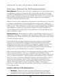
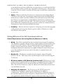
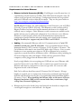
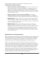
GRAVIMETRIC GATEWAY & ETHERNET COMMUNICATIONS Maguire Products, Inc. G2 Communications • Ethernet • Wireless Ethernet MAGUIRE PRODUCTS, INC. Gravimetric Gateway & Ethernet Communications Maguire Products, Inc. 11 Crozerville Road, Aston PA, 19014 Phone 610.459.4300 • Fax 610.459.2700 ii Table of Contents The Purpose of this Document Overview – Ethernet for G2 Communications Overview – Wired Ethernet Overview – Wireless Ethernet Benefits of Ethernet for G2 Communications Using Ethernet for G2 Communications General Requirements when using Ethernet (Wireless or Cabled) Requirements for Cabled Ethernet / Examples Requirements for Wireless Ethernet / Examples Wireless Ethernet for G2 Communications Wireless devices used in our wireless G2 testing Configuring a Wireless G2 Network / Examples Configuring Ethernet Devices Wireless Ethernet Bridge (WET11) Wireless Access Point (WAP11) Wireless Repeater (WAP11) Wireless Serial Server Ethernet to Serial Converter (G2-ES) Adding Ethernet Accessible Blenders in the G2 Software G2 Wireless Experimentation Wireless Test Results for G2 Communications Crossover cable Reference Diagram Contact Information 1 2 2 2 2 3 3 5 8 8 9 10 13 15 20 24 28 33 38 39 40 44 44 G R A V I M E T R I C G A T E W A Y A N D E T H E R N E T C O M M U N I C A T I O N S Purpose of this document T he purpose of this document is to give the reader an overview of several methods of using Ethernet, including wireless Ethernet to communicate with the Maguire Weigh Scale Blender controllers. The Maguire controllers are designed to be able to operate as a standalone unit unassisted by computer software. However, Maguire controllers also have the ability to communicate with software via the controllers COM port by using the publicly available MLAN (Maguire Local Area Network) protocol. Maguire Products has developed software to control and track the usage of material processed by the Maguire controllers. This software is called the Gravimetric Gateway Software or sometimes referred to as the G2 software or just G2. Typically the communication network from the G2 computer to the Maguire controllers has been a serial network using RS-232 cable to the Maguire controller, boosted by a serial signal amplifier. With the increasing deployment of Ethernet networks, the G2 software was developed to utilize TCP/IP over an Ethernet network as the method of communication to the Maguire controllers. This document will attempt to give the reader an understanding of how Ethernet including wireless Ethernet can be used to establish communications between a computer running not just the G2 software but also any software utilizing the MLAN protocol. There are a number of approaches to designing a communication network. No one approach works for all environments and situations. The optimal solution(s) in a particular network depends on factors such as the potential for electromagnetic interference (EMI), level of security required, size of the blender network and number of blenders, distance between the G2 computer(s) and the controllers, and so forth. Because of this diversity, this document will touch on the basics and provide examples as well as test results of experiments conducted in controlled situations. This document will also assume that the reader has a basic understanding of Windows based operating systems and a general understanding of an Ethernet network. With basic knowledge of an Ethernet network and configuring Ethernet in a Windows operating system, the read can use this document to implement Ethernet for G2 communications. For a further understanding of the G2 Software, please read the Gravimetric Gateway a Manual available online at www.Maguire.com/g2. G2 and Gravimetric Gateway Software is registered trademarks of Maguire Products Inc. Linksys is a registered trademark of the Linksys, a division of Cisco Systems, Inc. GW21W-MAXI is a registered trademark of Atop Technologies, Inc. Moxa NPort DE-211 is a registered trademark of Moxa Technologies Co., Ltd. 1 G R A V I M E T R I C G A T E W A Y A N D E T H E R N E T C O M M U N I C A T I O N S Overview - Ethernet for G2 Communications Wired Ethernet – Ethernet can be used for G2 communications. In a typical situation this is accomplished by running a U/L approved CAT5 or better Ethernet cable to each blender controller from an Ethernet hub or switch and converting the serial port at the controller to Ethernet using an Ethernet to Serial converter (G2-ES). The G2 Server PC is connected to the Ethernet hub (or switch) and the G2 software is then configured to access the Maguire controller via Ethernet rather than by serial. Ethernet can also be used to supplement a serial network in several different ways. One way is to configure certain blenders to use Ethernet while others remain as serial. Another way might be to break a large serial network of blenders into several branches using an Ethernet to serial converters. Then each branch is converter back to serial and amplified using an MLAN Signal amplifier to continue out to the network of blenders. Yet another possibility is to connect multiple plants to a single G2 Server using Ethernet or even wireless Ethernet if the plant are within line of sight. Wireless Ethernet - Wireless Ethernet is similar to cabled Ethernet with the exception of using wireless technology to communicate rather than Ethernet cabling. This documentation will detail necessary wireless components, basic wireless settings and wireless security settings for an 802.11b wireless network. Wireless Ethernet has advantages and disadvantages when compared to serial or Ethernet networks for G2 communications. Advantages include eliminating the need to install communication lines and a greater flexibility for reconfiguring a communications network. Disadvantages may include greater security risk and difficulty establishing a wireless connection due to “dead spots” in the wireless topography both of which can be addressed through security control methods and use of repeaters to extend the signal. When incorporating wireless into your G2 communication network, each Maguire controller must be converted to Ethernet. This can be accomplished with an Ethernet to serial converter and a wireless bridge (two separate devices) or a device that combines both into one device as a Wireless Serial Server. This documentation will detail both concepts. At the G2 Server PC location, the G2 Server’s Ethernet port must be converted to wireless or access to the wireless network through a wired network. This document will detail the use of a wireless Access Point (AP) as well as a wireless Ethernet Bridge at the G2 Server location. When a wireless signal requires a boost in strength due to distance, obstructions or interference, a repeater can be used. This document will detail the use of a Wireless Access Point in Repeater Mode. Benefits of Ethernet for G2 Communications • Reliability - Ethernet uses data correction at the hardware level, meaning the network devices detect errors in communication and re-transmit packets before information ever gets to the G2 software or the controller. This error correction 2 G R A V I M E T R I C G A T E W A Y A N D E T H E R N E T C O M M U N I C A T I O N S occurs much faster and more reliably than error detection over a serial network where the G2 software and the controllers are responsible for detecting error. The end result is that the G2 Server and the controllers will always get successful data communication at a faster rate. • Speed - Ethernet enables the G2 software to communicate with multiple Maguire controllers at the same time. Even though communications between the Ethernet to Serial converter and the controller is limited to the serial baud rate (by default 1200), the G2 Server can communicate to multiple Ethernet Serial Servers simultaneously, thus multiple controllers at the same time. The result is an increase in communication speed. With serial communications, the G2 software is limited to communications to one blender at a time across the serial MLAN network. • Flexibility - Ethernet offers more options for configuring your network topography yielding benefits such as: greater distances, greater number of blenders on a single network and wireless options. Using Ethernet for G2 Communications General Requirements when using Ethernet (Wireless or Cabled) • G2-SA – The G2-SA is the black box that is included with a licensed G2 installation. The “Black Box” typically is known as being a signal amplifier, but also doubles as the security key for the G2 Server. This security key dictates the licensing features and blender count purchased by the customer. The G2–SA is require in all licensed installations and must be connected to an available COM port on the G2 Server PC, even if the installation does not use serial as the means of communication to the Maguire blenders. • Blender I.D. – The Maguire controllers must be assigned a unique ID number between 1 and 254. This is done at the controller keypad of each controller using the *66 function. • G2 Server requires a NIC (Network Interface Card) –If Ethernet is to be the primary means of communications to the Maguire controllers, then the G2 Server PC must have an installed network card and also have the TCP/IP protocol installed. Note: The G2 Server must have a fixed I.P. address if G2 Clients will access the server over the Ethernet network. • Assigning I.P. Addresses – The G2 Server uses the TCP/IP protocol to communicate with Maguire controllers when Ethernet is the method of communication. Therefore the I.P. address of the G2 Server, all Ethernet devices at the controllers (Ethernet to Serial Converters or Wireless Serial Server depending on your application), and all G2 Client PCs must be in the same subnet range to enable 3 G R A V I M E T R I C G A T E W A Y A N D E T H E R N E T C O M M U N I C A T I O N S them to communicate with each other. For example if the G2 Server has an I.P. address of 192.168.1.100, then the G2 Client PCs and Ethernet to serial converters must be assigned I.P. address ranging from 192.168.1.1 to 192.168.1.254 without duplications. For TCP/IP configuration information beyond what is provided in this document, contact a network administrator. • G2 Software Configuration – When a blender is configured to use Ethernet, (whether cabled or wireless) it is added to the G2 software in the Blender Edit screen. The blender is added as a “TCP/IP Access” type blender. The information that allows the G2 software to access the blender over Ethernet are: The Blender ID, the I.P. address of the controller’s Ethernet device (labeled “WSB I.P.”) and the “Port” that the Ethernet device is listening on. This information is the same whether wired or wireless. 4 G R A V I M E T R I C G A T E W A Y A N D E T H E R N E T C O M M U N I C A T I O N S Requirements for Cabled Ethernet • Ethernet to Serial Converter (G2-ES) – Each Maguire controller must have it’s own Ethernet to Serial Converter (G2-ES). Each G2-ES must be assigned a static I.P. address as well and specific serial settings. Configuration instructions are provided with each G2-ES and are also within this document. They are also posted online at http://www.maguire.com/page.php/g2manuals.htm. NOTE: Maguire Products, Inc. sells an Ethernet to Serial Converter, part # G2-ES-11 (110 volt), or part # G2-ES-12 (220 volt). This Ethernet to serial converter sold by Maguire Products, has been tested and documented and shown to be reliable and relatively easy to configure. Other Ethernet to serial converters are available on the market and may vary in quality and configuration. If you choose to use a different Ethernet to serial converter, please refer to the manufacturers instructions for configuration. Specific Ethernet and serial settings can be found in this document. Maguire Products, Inc. supports only the G2-ES-11 and G2-ES-12. • Cabling – Recommended Ethernet cable for G2 communications is: Cat5e STP (shielded, twisted pair), 24AGW solid cable. Cat5 is acceptable but has a shorter maximum distance; CAT5 is rated to 100 meters, CAT5e is rated to 350 meters. The Cat5e Ethernet cable must be run from G2-ES back to the G2 Server. If two or more blenders are in use requiring more than one G2-ES, an Ethernet hub or switch is required as a central junction for all Ethernet cables. All Ethernet cables, including the G2 Server’s Ethernet cable, each blender’s G2-ES, and any optional G2 Client computers, will be plugged into the Ethernet hub or switch. If only a single blender is in use requiring one G2-ES and one run of Ethernet cable from the G2 Server PC to the G2-ES, a hub or switch is not require however the Ethernet cable must be configured as a crossover type cable. See crossover cable diagram at the end of this document. Each Cat5e cable run should not exceed 350 meters (Cat5 100 meters). If longer lengths are required, use of a repeater may be necessary to maintain signal strength. Stranded cable should not be used due to its significantly limited maximum distance (10 meters, 33 feet). When installing the Ethernet cable, avoid sources of ElectroMagnetic interference (EMI) such as vacuum loader lines, transformers, high voltage lines, florescence lighting, etc. • Ethernet may be used to break a large serial network into branches to improve the overall signal strength on a serial network. See diagram. 5 G R A V I M E T R I C G A T E W A Y A N D E T H E R N E T C O M M U N I C A T I O N S Below is a diagramed example of a wired Ethernet network Key points in the diagram above: • Each Maguire Weigh Scale Blender is connected directly to it’s own G2-ES through a special Null Modem serial cable (provided with the G2-ES). Each G2-ES includes its own 12-volt transformer and must be supplied power within 6 feet of the G2-ES. • All Ethernet cables (Cat5e Shielded Twisted Pair or better recommended) are run back to a centrally located Ethernet hub or switch. The G2 Server PC is also connected to the Hub as well as any optional G2 Client PCs. The path of the Ethernet cables should avoid: high voltage lines, vacuum loader lines, transformers or anything that may cause interference. • The G2-SA is connected to the G2 Server’s COM Port. The G2-SA contains the security key, which is required for licensing. The G2-SA is also a signal amplifier, which is used in serial communication applications. In Ethernet applications, the G2-SA is only used as a security key. Note: It is possible to use both a serial and an Ethernet network at the same time for G2 communications. When multiple network types are used at the same time (Ethernet and Serial), each blender will be configured in G2 specific to how it communicates. • Each cable is terminated at both ends with RJ-45 modular connectors designed for shielded, solid cable. Wiring configurations typically are T568B wiring patterns. 6 G R A V I M E T R I C G A T E W A Y A N D E T H E R N E T C O M M U N I C A T I O N S Below is a diagramed example of using Ethernet to break up a large serial network – In the diagram above, a large serial network with an excess of 30 blenders is broken into 4 branches. Branch 1, branch 2 and branch 3 are using an Ethernet to Serial converter to convert Ethernet communications from the G2 Server to serial using the G2-ES. The output of each G2-ES is then boosted using a signal amplifier (MLANSA) and then out to the network of blenders. Multi-branch Serial Network Branch 4 is using the G2 Server’s own serial port and the G2-SA to communicate with that group of blenders. The primary reason for using a configuration such as this would be to improve troublesome communications of a network of blender that is currently using a single COM port on the G2 Server through the G2-SA out to the entire network of blenders. In the typical serial installation, approximately 25 blenders is the maximum that a single serial network can handle without loss in communications. Some blender networks can handle more blenders others less depending on factors such as distance, wire quality, electrical interference. The example above was used in a location where 68 blenders were in operation on a single blenders serial network. By using the G2-ES the network could be split up into serial networks with fewer than 20 blenders per branch. A side benefit to this configuration is increased communications speed where the G2 Software could communicate with multiple branches at one time. 7 G R A V I M E T R I C G A T E W A Y A N D E T H E R N E T C O M M U N I C A T I O N S Requirements for Wireless Ethernet • G2 Server’s Ethernet to Wireless Ethernet – The G2 Server must have access to the wireless network. This can be accomplished by converting the G2 Server’s Ethernet port to wireless using a Wireless Access Point or a Wireless Bridge. The Wireless Access Point may be located somewhere on the wired network. If a wireless bridge is used at the G2 Server, then a Wireless Access Point must be used and located within communication range. • Maguire Controllers must be converted to Wireless – The Maguire controllers must have access to the wireless network. This can be accomplished by using a Wireless Serial Server, which combines Serial to Ethernet and wireless devices. • Using Repeaters – Repeater can be used to “repeat” the wireless signal. Repeaters may be necessary if: conditions weaken the wireless signal so that communications cannot be established. Conditions may include distance, interference, and obstructions such as walls or the plant floor layout. • Wireless Security – When wireless technology is used, security becomes an important part of the configuration. In a wired network, jacks are located inside buildings already secured from unauthorized access. In contrast, a wireless access point (AP) may be accessed from off the premises if the signal is detectable (for instance, from a parking lot adjacent to the building). This document outlines basic security control methods that form the basis of the 802.11b architecture used by the wireless devices in this document. Wireless Ethernet for G2 Communications Maguire Products has conducted limited tests using wireless Ethernet for G2 communications. Based on these limited tests, some information has been collected and documented that may assist in installing a wireless network for the purpose of G2 communications. Additional measures that are not documented here may be possibly to increase performance. The purpose of this document is to establish a working model of a G2 wireless network. There are a variety of wireless devices on the market. This document will deal with the specific, readily available devices that were used in the tests. These devices were tested using settings that were found to maintain the best possible wireless connection in an environment similar to what may be found in a typical plant floor. Although this document will detail how our devices were configured to establish a wireless G2 network, this document is not meant to serve as a complete “how-to”, but rather as a reference paper to provide some additional information to an installer who is already familiar with installing wireless Ethernet networks. Installers should read the manufacturers documentation and instructions for additional information on the devices used in the following examples. 8 G R A V I M E T R I C G A T E W A Y A N D E T H E R N E T C O M M U N I C A T I O N S Devices used in our wireless testing: The GW21W-MAXI is a device combining the Ethernet to Serial converter (NPort DE-211) and the wireless Ethernet Bridge (WET11). It is configured and connected to the Maguire controller using a serial cable. When installing the GW21W-MAXI, consideration should be given to avoiding obstructions, high voltage, interference from vacuum loader lines, etc. • GW21W-MAXI Wireless Serial Server – • Linksys WAP11 (Access Point Mode) – • Linksys WAP11 (Repeater Mode) - • NPort DE-211 Ethernet to Serial Converter – • Linksys WET11 – The WAP11 in access point mode acts as the central wireless point for all wireless communications on the wireless network. The WAP11 device is configured and placed in one of several possible positions in the wireless network, depending on the layout of the plant. See wireless diagrams for possible locations. The WAP11 in repeater mode serves as a wireless repeater for the device it is configured to repeat. In testing, it was setup to extend the distance from the WAP11 (Access Point) to the Maguire controllers. If needed the WAP11 in repeater mode can be placed at a location in the wireless network where there is a need to boost the signal of the Access Point to reach Maguire controllers. See wireless diagrams for possible locations. The NPort DE-211 is an Ethernet to Serial converter and does not have wireless built into the device. This device would only be used if it is already presently installed at the controller with a wired Ethernet network and wireless Ethernet is desired instead. If this is the case, then this device is used with the wireless Ethernet Bridge below. The Linksys WET11 is a wireless Ethernet bridge that converts Ethernet to the 802.11b wireless. The WET11 can be used to convert the G2 Server’s Ethernet port to wireless Ethernet. In some applications the WET11 may be used with the Ethernet to Serial converter (typically only if the G2-ES’s are already present). The WET11 would be configured and installed at the controller to convert wired Ethernet (at the G2-ES) to Wireless Ethernet. The Ethernet port on the WET11 is connected to the Ethernet port on the NPort DE-211. This device should be positioned where it may obtain the best wireless signal possible. Consideration should be given to avoiding obstructions, high voltage, interference from vacuum loader lines, etc. If there is no existing G2-ES units, Maguire Products recommends using the GW21W-MAXI. 9 G R A V I M E T R I C G A T E W A Y A N D E T H E R N E T C O M M U N I C A T I O N S Configuring a Wireless G2 Network In the next few pages, several wireless networks are diagramed to illustrate several possible configurations. The requirements of your wireless G2 network will depend on factors such as distance, physical layout of the plant floor, the presence of obstructions such as walls or machinery. Other factor may include the existing of a wired Ethernet network where other computers require access to the G2 Server, such as computers running the G2 Client software. Read this section to determine what wireless devices you may need. Key Points to configuring your Wireless G2 Network • theoretical distance of wireless 802.11b is typically specified much greater than what real world installations can achieve. In most of our wireless testing, the maximum distance that we were able to communicate without repeating the signal was approximately 150 to 250 feet depending on obstructions. Line of sight yields the best signal and possibly much greater distance. When line of sight was not possible, placement of a WAP11 in Repeater Mode between the WAP11 and the Maguire controllers can reestablished a connection. • Location of Devices – • Wireless Security – • Transmission Rate – Distance –The The location of the wireless devices, more specifically the antenna of the wireless devices, can determine to quality of the signal. When possible, locate the wireless devices so that the antennas are within line of sight of each other. This will yield the best signal. If line of sight is not possible, locate the devices so that they have the least obstructs between devices. Potential interference sources to a wireless network that should be avoided may include 2.4 GHz cordless phones, vacuum loader lines, high voltage lines or transformers or the like. Note: In some cases wireless antennas can be detached from the wireless device and remote mounted using an antenna mounting system, which uses an extension cable and in some cases a magnetic mount base that accepts the antenna. It was found in our testing that there was a significant loss of signal quality when a remote antenna system such as this was used therefore it is not recommended. Because security is an issue with a wireless Ethernet network, use of several security measures are recommended. They are: SSID – Short for service set identifier, it is a maximum 32-character unique identifier attached to the header of packets sent over a WLAN that acts as a password. The SSID must be the same on all wireless devices in your wireless network. Disabling the SSID Broadcast is also recommended. Wired Equivalent Privacy WEP - WEP is a security protocol, specified in the IEEE Wireless Fidelity (Wi-Fi) standard, 802.11b, that is designed to provide a wireless local area network (WLAN) with a level of security and privacy comparable to what is usually expected of a wired LAN. WEP uses a 64-bit or 128-bit encryption key (sometimes generated from a passphrase). The Transmission Rate is the rate at which communication is sent and received from the wireless device to wireless device. In our test, the higher 10 G R A V I M E T R I C G A T E W A Y A N D E T H E R N E T C O M M U N I C A T I O N S the Transmission Rate, the lesser the distance we were able to communicate. It was found that the lowest setting of 1 Mbps achieved the best results. The following diagrams illustrate several possible wireless networks. Wireless diagram 1 – This is the most basic wireless layout. In this diagram the G2 Server’s Ethernet port is connected directly to a WAP11’s Ethernet port using a crossover cable (or sometimes referred to as a station-to-station cable). The WAP11 converts the G2 Server’s Ethernet communication to wireless. Each Maguire Controller has a Wireless Serial Server. The G2 communications are transmitted wireless between the WAP11 and each Wireless Serial Server. Wireless diagram 2 – In this diagram the G2 Server’s Ethernet port is connected directly to the WAP11’s Ethernet port using a crossover cable. Each Maguire Controller has a Wireless Serial Server. The wireless signal is boosted by a WAP11 in Repeater Mode located between the G2 Server and the controllers. The G2 communications are transmitted via wireless from the WAP11, repeated by the WAP11 in Repeater Mode, and then to each Wireless Serial Server. The Repeater may also be used to reestablish communications in a “dead spot” in the wireless 11 G R A V I M E T R I C G A T E W A Y A N D E T H E R N E T Wireless diagram 3 – In this diagram the G2 Server’s Ethernet is connected to the WET11 Wireless Bridge (crossover cable not required, use X- II switch). Each Maguire Controller has a Wireless Serial Server. The G2 communications are transmitted via wireless from the WET11, to the WAP11, and then to each Wireless Serial Server. The primary reasons for using a wireless bridge (WET11) to centrally locate the WAP11 in the wireless network for better performance. Wireless diagram 4 – In this diagram the G2 Server’s Ethernet is connected to an existing local area network. The WAP11 is also connected to the local area network. Each Maguire Controller has a Wireless Serial Server. G2 communications are sent across the network and then transmitted via wireless between the WAP11, and then to each Wireless Serial Server. G2 Client machines are able to access the G2 Server via the local area network. In this as well as all diagrams, repeaters may be used to improve performance of the wireless network. 12 C O M M U N I C A T I O N S G R A V I M E T R I C G A T E W A Y A N D E T H E R N E T C O M M U N I C A T I O N S Configuring Ethernet Devices Before you begin: Using Static IP Addresses The Gravimetric Gateway software uses the TCP/IP protocol to communicate. This includes communications between the G2 Server and Clients as well as with controllers using Ethernet, whether wired or wireless. TCP/IP (Internet Protocol) uses IP settings to route data packets. IP settings can either be dynamic (automatically assigned by a DHCP server) or static (meaning it is specified in the properties of the TCP/IP protocol). If the G2 Server is communicating with controllers using Ethernet, the IP address of each controller must be a static IP address. If G2 Client computers on a network are to connect to a G2 Server on another computer on a network, the Client PC must specify the G2 Server by IP address, therefore the G2 Server’s IP address must be known when connecting to the G2 Server. For those reasons we recommend using static IP addresses for the G2 Server PC, Ethernet to Serial converters and Wireless Serial Servers. All Ethernet devices including the G2 Server and G2 Client PCs must use IP settings in the same range so they can access each other. Before configuring your Ethernet devices have your IP settings ready. 13 G R A V I M E T R I C G A T E W A Y A N D E T H E R N E T C O M M U N I C A T I O N S Wireless Security Wireless transmissions are easier to intercept than transmissions over a wired network. Therefore use of security is highly recommended. Basic wireless security provided two methods of implementing security. They are SSID and WEP. SSID (Service Set Identifier) – Much like a password, this is a unique name shared among all points in a wireless network. The SSID must be identical at each point in the wireless network. It is case sensitive and may consist of any character on your keyboard. Choose an SSID that is more secure, preferably using a combination of letters and numbers. SSID Broadcast should be disabled. WEP (Wired Equivalent Privacy) – Enabling Wired Equivalent Privacy (WEP) on the wireless devices requires you to enter a WEP key (or a passphrase that will generate a Key). Valid WEP keys are 64 and 128 bit for Linksys products and 40-bit and 128-bit for the wireless serial server. WEP setting must be identical to all wireless points on your network. Both Linksys and the GW21W-MAXI support 128-bit therefore we recommend you use 128-bit on your wireless G2 network. For all Linksys products, a passphrase can be entered and a key automatically generated. For Wireless Serial Servers, only a key may be entered. If you generate a 128-bit key from a passphrase, write down the key so that you may later enter it into your Wireless Serial Server. When choosing a WEP passphrase, use one that is secure, preferably using a combination of letters and numbers. 14 G R A V I M E T R I C G A T E W A Y A N D E T H E R N E T C O M M U N I C A T I O N S Wireless Ethernet Bridge (WET11) Linksys WET11 Wireless Ethernet Bridge. This configuration setup guide will follow the WET11’s Quick Installation Guide, packaged with the WET11 and include the recommended settings for configuring the WET11 for wireless G2 communications. How the WET11 is used in the G2 network: • • Converting a G2 Server PC or G2 Client PCs to 802.11b wireless Can be used in combination with the G2-ES to convert the G2-ES to wireless What you will need to know to configure this device: ! ! ! IP address, Subnet Mask and Gateway for the WET11 SSID – Network name used on for your wireless bridge (must be the same on all wireless devices) Wired Equivalent Privacy WEP (128-bit recommended) – Secure passphrase will be entered Configuration: (Note: Linksys Screen shots may differ from this documentation) STEP 1 – Connecting the WET11 Wireless Bridge A. Plug the included Ethernet network cable into the LAN port on the back panel of the WET11 Wireless Ethernet Bridge. B. The X-II selection offers a choice between two settings. Slide the X-II selection switch to the X position if you are connecting the WET11 directly to the network card of the G2 Server or G2 Client or directly to the G2-ES. Slide the X-II selection switch to the II position if you are connecting the WET11 to a hub or switch. C. Plug the other end of the Ethernet network cable into your RJ-45 port on your G2 Server (or G2 Client), or into an open port on your network hub or switch. D. Plug the supplied power cable into the Power port on the back panel of the WET11. Then plug the other end into an electrical outlet. 15 G R A V I M E T R I C G A T E W A Y A N D E T H E R N E T C O M M U N I C A T I O N S STEP 2 – Setup of the WET11 Wireless Bridge A. Insert the Linksys Setup Wizard CD-ROM into your CD-ROM drive. (This CD is included with the Linksys WET11 Wireless Ethernet Bridge). The Setup Wizard should run automatically, and the Welcome screen should appear. If it does not, click the Start button and choose Run. In the box that appears, enter d:\setup.exe (where “D” is the drive letter of your CD-ROM drive). B. To set up your Wireless Ethernet Bridge, click the Setup button. C. This screen shows two ways to configure the WET11 using this Setup Wizard. For this example, the way that the WET11 will be used is the B. configuration. Click the Next button. D. The Setup Wizard will search for any WET11 Wireless Bridges connected to the PC or to the network. It will then display a list of WET11 Bridges found on your network. If you have only one Bridge connected to your network, it will be the only one displayed. Select the Bridge you are currently installing by clicking its name in the Selection box. Click the Yes button. E. For security purposes, you will be asked for your password in order to access the Bridge. In lowercase letters, enter admin in the Password field. Click the Ok button. 16 G R A V I M E T R I C G A T E W A Y A N D E T H E R N E T C O M M U N I C A T I O N S F. This screen shows a choice of two wireless modes. Since a wireless G2 network will require an access point, select Infrastructure Mode and click next. G. The Basic Settings screen will now appear. Enter your wireless network SSID. For this example we are using G2-WIRELESS. For Infrastructure Mode, the Channel will not be selected. Enter a unique Bridge Name for this Wireless Ethernet Bridge device. Click next. H. The IP Settings screen will now appear. It is recommended that the G2 network have static IP addresses. Click the radio button next to Set IP configuration manually. Enter an IP Address, IP Mask (also known as Subnet Mask), and Gateway for your network. If you are unsure about the IP Mask and Gateway, it is better to leave these two fields blank. Click next to proceed. I. The Security Setting screen will appear. Set the Wired Equivalent Privacy (WEP) encryption for your wired network. It is recommended that you use the 128-bit WEP configuration method. For 128-bit WEP, enter a passphrase in the Passphrase field. A passphrase is 17 G R A V I M E T R I C G A T E W A Y A N D E T H E R N E T C O M M U N I C A T I O N S the code used when logging a wireless device onto the wireless network. The passphrase is case-sensitive and should not be longer than 16 alphanumeric characters. This passphrase will be used with the WAP (wireless access point) and the WAP in repeater mode. When complete, click the Next button. J. On the WEP Key Settings screen, you will see the automatically generated WEP key. This key should be recorded so that it may be used later when configuring the Wireless Serial Servers. Click next. K. Review your settings. If these settings are correct, click the Yes button. If any of these settings are wrong, click the Back button to make changes. The basic configuration is complete. To activate the new settings, reset the Bridge by turning off the Bridge (unplug), wait a few seconds and turning it back on again. Further setting changes will be required and the WET11 will need to be access via a web browser to make the necessary setting changes. 18 G R A V I M E T R I C G A T E W A Y A N D E T H E R N E T C O M M U N I C A T I O N S Advanced Wireless Setting Changes to the WET11 A. Open a web browser such as Internet Explorer. B. Enter the IP address of your WET11 into the address field. Example: http://192.168.1.225 (replacing 192.168.1.225 with your IP address). C. When prompted for a user name and password, leave the username blank and enter the default password admin D. You should be presented with a web page of LAN and wireless settings. Scroll to the bottom of that page and click Advanced Wireless Settings. E. A new browser window should pop up with advanced wireless settings. Change the Transmit Rate to 1 then click apply, and then Ok. Close the advanced settings window. F. If you wish to change the password of the WET11 at this time, click the Password tab. Enter a new password and enter it again to confirm. Click Apply. You should be prompted for a password again. Enter Admin as the user name and enter your new password. G. Configuration of the WET11 is complete. Close the browser window. 19 G R A V I M E T R I C G A T E W A Y A N D E T H E R N E T C O M M U N I C A T I O N S Wireless Access Point (WAP11) Linksys WAP11 Wireless Access Point This setup guide will follow the WAP11’s Quick Installation Guide, packaged with the WAP11 with the addition of specifying the recommended settings for configuring the WAP11 for wireless G2 communications. How the WAP11 is used in the G2 network: • Serves as the central Access Point to a Wireless-B network. Can be connected directly to the G2 Server PC (using a crossover cable) or located in the center of the wireless network. All wireless devices will communicate through the WAP11. • The WAP11 can be configured as a Repeater to repeat wireless communications from another wireless device such as a WAP11 Access Point. When configured as a Repeater, the hardware address of the device to repeat will be specified in the repeater. See Wireless Repeater (WAP-11) for more details on using the WAP-11 as a Repeater. What you will need to know to configure this device: ! ! ! ! IP address, Subnet Mask and Gateway for the WAP11 SSID – Network name used on for your wireless bridge (must be the same on all wireless devices) Wired Equivalent Privacy WEP (128-bit recommended) – Secure passphrase will be entered For Repeater Mode, you will need the hardware address of the WAP11 it will repeat. See Wireless Repeater Configuration: (Note: Linksys Screen shots may differ from this documentation) STEP 1 – Connecting the Wireless-B Access Point A. Configuring the Wireless Access Point requires that it be connected directly to the wired network into a hub or switch using the included Ethernet network cable. You may also connect it directly to the G2 Server ONLY if you use a crossover type cable (sometimes referred to as a station-to-station cable). Crossover diagram is included at the end of this document. After configuration, the optimum location of the WAP11 is usually at the center of your wireless network, within line of sight to your wireless devices. Usually the higher you place the Access Point, the better the performance will be. The WAP11 will either be connected to your G2 Server PC or, the WAP11 will be connected to your wired network. 20 G R A V I M E T R I C G A T E W A Y A N D E T H E R N E T C O M M U N I C A T I O N S B. Adjust the direction of the antennas. Both should be perpendicular to the ground and parallel to each other. C. Connect the power adapter to the Access Point’s Power port. STEP 2 – Setup of the WAP11 Wireless Access Point A. Insert the Linksys Setup Wizard CDROM into your CD-ROM drive. (This CD is included with the Linksys WAP11 Wireless Access Point). The Setup Wizard should run automatically, and the Welcome screen should appear. If it does not, click the Start button and choose Run. In the box that appears, enter d:\setup.exe (where “D” is the drive letter of your CD-ROM drive). To set up your Wireless Ethernet Bridge, click the Setup button. B. Make sure your WAP11 is connected to your wired network so that you can configure the WAP11 through any PC on your wired network. Then Click Next. C. The next screen displayed will have a list of Wireless Access Points on your network, along with the status information of each access point. Select the WAP11 that to configure by clicking it’s name. Then click Yes. D. On the Enter Network Password screen, enter the Access Point’s default password, admin, in the password field. Then click Ok. 21 G R A V I M E T R I C G A T E W A Y A N D E T H E R N E T C O M M U N I C A T I O N S E. The Basic Settings screen will appear. Enter a unique name in the AP Name field. The IP Settings screen will now appear. It is recommended that the G2 network have static IP addresses. From the network settings drop-down menu, select Static IP. Enter an IP Address, Subnet Mask appropriate for your network. Click Next to proceed. F. The Basic Wireless Setting screen will appear. Enter your wireless network’s SSID. For this example we are using G2WIRELESS. The wireless channel can be left at the default setting. Then click Next. G. The Security screen will appear. Select the level of Wired Equivalency Privacy (WEP) encryption for your network. If you are using a passphrase, enter the passphrase into the passphrase field. If you will be entering a WEP key, leave the passphrase field blank. Then click Next. H. The second Security screen shows the WEP key. If you entered a passphrase, then the Key 1 field will display the automatically generated WEP key. If you did not enter a passphrase then enter the WEP key into the Key 1 field. Click Next. The WEP key will be require when configuring the Wireless Serial Server so if a key was automatically generated from a passphrase, record the WEP key at this time. 22 G R A V I M E T R I C G A T E W A Y A N D E T H E R N E T C O M M U N I C A T I O N S I. On the next screen, review your settings. If they are correct, click Yes. If they are not correct, exit the wizard and restart this section again. Advanced Wireless Setting Changes A. Open a web browser such as Internet Explorer. B. Enter the IP address of your WAP11 into the address field. Example: http://192.168.1.251 (replacing 192.168.1.251 with your IP address). C. When prompted for a user name and password, leave the username blank and enter the default password admin D. You should be presented with a web page of Setup information. Click the advanced tab at the top of the page. E. Click the Wireless tab at the top of the page. F. Change the Basic Rates to 1-2(Mbps) G. Change the Transmission Rates: to 1-2(Mbps) H. Change the SSID Broadcast: to Disable I. Click Apply J. At this time if you want to change the password to the WAP11, you can click the Setup tab at the top of the screen and then click the Password tab. To change the password, enter a new password and once again to confirm it. Click Apply. You will be prompted to re-enter your password. K. At this time you have completed the configuration of the WAP11 and may close the web browser. 23 G R A V I M E T R I C G A T E W A Y A N D E T H E R N E T C O M M U N I C A T I O N S Wireless Repeater (WAP11) Linksys WAP11 Wireless Access Point In Repeater Mode This setup guide will follow the WAP11’s Quick Installation Guide, packaged with the WAP11 with the addition of specifying the recommended settings for configuring the WAP11 for wireless G2 communications as a Repeater. How the WAP11 is used in the G2 network: • The WAP11 in Repeater Mode serves as a repeater to another wireless device such as an Access Point (WAP11). It can be located in the center of the wireless network or strategically placed to extend a wireless signal to a dead zone in your wireless network. The WAP-11 in Repeater Mode does not require it to be connected to anything other than a power source. • Location of a Repeater should be within range of the device it will repeat. What you will need to know to configure this device: • • • • IP address, Subnet Mask and Gateway for the WAP11 Repeater SSID – Network name used on for your wireless bridge (must be the same on all wireless devices) Wired Equivalent Privacy WEP passphrase or key (128-bit recommended) When used in Repeater Mode, you will need the hardware address or MAC address of the device it will repeat. In most cases it will be another WAP11 Wireless Access Point. The MAC address can be found usually on the bottom of the unit itself or can be found in the web browser accessible configuration on the Status configuration screen and labeled MAC address. Configuration: STEP 1 – Connecting the Wireless-B Access Point Configuring the Wireless Access Point requires that it be connected directly to the wired network into a hub or switch using the included Ethernet network cable. You may also connect it directly to the G2 Server ONLY if you use a crossover type cable (sometimes referred to as a station-to-station cable). Crossover diagram is included at the end of this document. Later, after configuration, it can be disconnected from the network and placed in the location where it is needed. Antennas should be perpendicular to the ground and the Repeater should be placed high above the ground for better performance. 24 G R A V I M E T R I C G A T E W A Y A N D E T H E R N E T C O M M U N I C A T I O N S STEP 2 – Setup of the WAP11 Repeater A. Insert the Linksys Setup Wizard CDROM into your CD-ROM drive. (This CD is included with the Linksys WAP11 Wireless Access Point). The Setup Wizard should run automatically, and the Welcome screen should appear. If it does not, click the Start button and choose Run. In the box that appears, enter d:\setup.exe (where “D” is the drive letter of your CD-ROM drive). To set up your Wireless Ethernet Bridge, click the Setup button. B. Make sure your WAP11 is connected to your wired network so that you can configure the WAP11 through any PC on your wired network. Then Click Next. C. The next screen displayed will have a list of Wireless Access Points on your network, along with the status information of each access point. Select the WAP11 that to configure by clicking it’s name. Then click Yes. D. On the Enter Network Password screen, enter the Access Point’s default password, admin, in the password field. Then click Ok. 25 G R A V I M E T R I C G A T E W A Y A N D E T H E R N E T C O M M U N I C A T I O N S E. The Basic Settings screen will appear. Enter a unique name in the AP Name field. The IP Settings screen will now appear. It is recommended that the G2 network have static IP addresses. From the network settings drop-down menu, select Static IP. Enter an IP Address, Subnet Mask appropriate for your network. Click Next to proceed. F. The Basic Wireless Setting screen will appear. Enter your wireless network’s SSID. For this example we are using G2WIRELESS. The wireless channel can be left at the default setting. Then click Next. G. The Security screen will appear. Select the level of Wired Equivalency Privacy (WEP) encryption for your network. If you are using a passphrase, enter the passphrase into the passphrase field. If you will be entering a WEP key, leave the passphrase field blank. Then click Next. H. The second Security screen shows the WEP key. If you entered a passphrase, then the Key 1 field will display the automatically generated WEP key. If you did not enter a passphrase then enter the WEP key into the Key 1 field. Click Next. The WEP key will be require when configuring the Wireless Serial Server so if a key was automatically generated from a passphrase, record the WEP key at this time. 26 G R A V I M E T R I C I. G A T E W A Y A N D E T H E R N E T C O M M U N I C A T I O N S On the next screen, review your settings. If they are correct, click Yes. If they are not correct, exit the wizard and restart this section again. Advanced Wireless Setting Changes A. Open a web browser such as Internet Explorer. B. Enter the IP address of your WAP11 into the address field. Example: http://192.168.1.251 (replacing 192.168.1.251 with your IP address). C. When prompted for a user name and password, leave the username blank and enter the default password admin D. You should be presented with a web page of Setup information. E. On the SETUP page, Under AP Mode select Repeater F. In the Remote repeater MAC Address, enter the MAC address of the wireless device you want to repeat. Typically this might be the WAP11 Access Point. G. Click Apply H. Click the advanced tab at the top of the page. I. Click the Wireless tab at the top of the page. J. Change the Basic Rates to 1-2(Mbps) K. Change the Transmission Rates: to 1-2(Mbps) L. Change the SSID Broadcast: to Disable M. Click Apply N. At this time if you want to change the password to the WAP11, you can click the Setup tab at the top of the screen and then click the Password tab. To change the password, enter a new password and once again to confirm it. Click Apply. You will be prompted to re-enter your password. At this time you have completed the configuration of the WAP11 as a repeater and may close the web browser. 27 G R A V I M E T R I C G A T E W A Y A N D E T H E R N E T C O M M U N I C A T I O N S Wireless Serial Server This section will guide you through the setup of the GW21W-MAXI. GW21W-MAXI Single-Port Wireless Serial Server Configuration Methods: There are several ways to access the GW21WMAXI to configure or modify the configuration settings. For the initial setup of the GW21W-MAXI this example will use HyperTerminal through the console mode. How the GW21W-MAXI Wireless Serial Server is used in the G2 network: • The GW21W-MAXI connects directly to your Maguire Controller’s serial port, (Computer port). The GW21W-MAXI converts serial communications of the Maguire controller to wireless Ethernet. Each Maguire controller will have it’s own GW21WMAXI. What you will need to know to configure this device: ! ! ! ! IP address, Subnet Mask and Gateway for the GW21W-MAXI SSID – Network name used on for your wireless bridge (must be the same on all wireless devices) Wired Equivalent Privacy WEP (128-bit recommended) – WEP Key will be entered into the GW21W-MAXI (a passphrase not entered into the GW21W-MAXI) Serial Settings for the Maguire controller (settings are specified in the following instructions) Important Pre-configuration information – You will need a Null modem placed between the mini din to RS-232 DB-9 cable and your computer’s COM port in order to configure the GW21W-MAXI through console mode. Null modem not included with the GW21W-MAXI. How to configure the GW21W-MAXI using HyperTerminal by Console Mode 1. Power off the GW21W-MAXI 2. Set the MODE switch SW1 to ‘OFF’ and SW2 to ‘ON’. 3. Use a PC to connect to the GW21W-MAXI’s console with the supplied the mini din to RS-232 DB-9 cable placing a null modem adapter between the PC and the mini din to RS-232 DB-9 cable. Connect the din side of the jack to the GW21W-MAXI and the serial end of this jack to a null modem, then to your computer’s COM port. 28 G R A V I M E T R I C G A T E W A Y A N D E T H E R N E T C O M M U N I C A T I O N S 4. Open a Terminal program such as HyperTerminal. (Click the Start button, choose Run and type HYPERTRM.EXE, click ok) 5. Start a new connection and choose to connect using the COM port you have connected the GW21W-MAXI to on your PC. 6. Set the baud rate to 9600 bps for console port communication. Do not set it to 115200 bps, which may be specified in the GW21W-MAXI’s instructions. This is incorrect. 7. Set the Data bits to 8, Parity to None, Stop bits to 1, and Flow control to None. 8. Use the following instructions to configure the GW21W-MAXI. 9. After finishing the console settings, power off the GW21W-MAXI, put SW1 and SW2 back to the previous settings. Entering Console Mode 1. Verify your GW21W-MAXI. You should have SW1 in the OFF position and SW2 in the ON position. The mini din to RS-232 DB-9 cable should be connected to the GW21W-MAXI’s din port, The DB-9 side of the cable connected to a null modem, then to your computer’s COM port. If this is correct proceed with step 2. 2. With HyperTerminal open and connect to your COM port at 9600 bps, power on the GW21W-MAXI. 3. You will be presented with the following output to the HyperTerminal screen: ABLELink Ethernet-Serial Server User name:admin Password: 4. By default there is no password, press enter. You will see: Login ok 0.Exit 1.Overview 2.Networking Input choice and enter(0~5): 29 3.Security 4.Com1 5.WLAN G R A V I M E T R I C G A T E W A Y A N D E T H E R N E T C O M M U N I C A T I O N S 5. Press 2 then enter, you will see: Networking: IP 1. IP Address(10.0.50.100) 2. Gateway(10.0.0.254) 3. Subnet Mask(255.255.0.0) SNMP 4. SNMP(Enable) 5. SysName(name) 6. SysLocation(locaion) 7. SysContact(contact) Input choice and enter(1~7): 6. Select 1, enter the IP Address of your GW21W-MAXI 7. Select 2, enter the Gateway of your network 8. Select 3, enter the Subnet Mask for your network 9. Press Esc to return to the previous menu 10. Press 4 (Com#), you will see: COM1: 1. Link Mode(TCP Server/Virtual_Com Disabled/Filter disabled/4660 ) 2. COM Port(/CONSOLE/9600,None,8,1/None) 3. Keep Serial Buffer's Data While Connecting(Enable) 4. Packet Delimiter(2 ms) Input choice and enter(1~4): 11. Press 2, COM Port, you will see: COM Port: CONSOLE 1. Alias name(): 2. Baud rate(9600): 3. Parity(None): 4. Data bit(8): 5. Stop bit(1): 6. Flow control(None): Input choice and enter(1~6): 30 G R A V I M E T R I C G A T E W A Y A N D E T H E R N E T C O M M U N I C A T I O N S 12. Press 2, Baud rate Select (9) other, Input the baudrate as 1200 and press. Enter. Note: Some earlier firmware versions were unable to set the baud rate to 1200 baud by selecting (1)1200 due to a bug in firmware. Therefore we recommend using (9) other and entering 1200. 13. Press Esc to return to return to the previous menu. You will see: 0.Exit 1.Overview 2.Networking Input choice and enter(0~5): 3.Security 4.Com1 5.WLAN 14. Press 5, WLAN. You will see: WLAN: Associated: non-spec: 44:44:44:44:44:44 Current channel: : 10 Current Tx Rate: 2 Mbps 1. Topology(Infrastucture): 2. Transmission Rate(1 Mbps): 3. Ad-hoc Channel 1~14(3): 4. ESSID(): 5. WEP(OFF): Input choice and enter(1~5): 15. Press 2, Transmission Rate Set Transmission Rate to 1 Mbps (press 1) (Note: 1 Mbps was found to provide the best signal with greater distance and was less susceptible to interference.) 16. Press 4, ESSID Set your ESSID (SSID) to your wireless network's SSID. (example G2-WIRELESS) 17. Press 5, WEP 18. Press 3, wep128 19. Input Key No 1~4, press 1 (you will enter a 128-bit key into key #1) 20. You will see a format example and “Please input 13 bytes: Enter your 128-bit WEP key and press enter. Note: Prefix your WEP with 0x (Hex indicator) Example: 0x31323334353637383930414243 WLAN WEP: 31323334353637383930414243 31 G R A V I M E T R I C G A T E W A Y A N D E T H E R N E T C O M M U N I C A T I O N S 21. Press Esc to return to return to the previous menu. You will see: 0.Exit 1.Overview 2.Networking Input choice and enter(0~5): 3.Security 4.Com1 5.WLAN 22. To change the password of the GW21W-MAXI, press 3, Security. 23. Confirm to change password, enter the original password (by default it is blank, no password) 24. Enter your new password, then enter again to verify. That completes the configuration of the GW21W-MAXI. 32 G R A V I M E T R I C G A T E W A Y A N D E T H E R N E T C O M M U N I C A T I O N S Ethernet to Serial Converter (G2-ES) There are many Ethernet to Serial converters on the market. For this example, the Moxa NPort DE-211 is used. The DE-211, referred to as the G2-ES, has been testing and found to be reliable and currently in use in G2 communication networks. Maguire Products Inc. sells this Ethernet to Serial Converter as part # G2-ES-11 (110 volt), and G2-ES-12 (220 volt) Moxa NPort DE-211 1-Port Serial Device Server How the G2-ES is used in the G2 network: • The G2-ES connects directly to your Maguire Controller’s serial port, (Computer port). The G2-ES converts serial communications of the Maguire controller to 10BaseT Ethernet. Each Maguire controller typically will have it’s own G2-ES and all controller will communicate with the G2 Server over a wired Ethernet network. Other configurations are possible using the G2-ES. See network diagrams in this document for examples. What you will need to know to configure this device: ! ! IP address, Subnet Mask and Gateway for the G2-ES Serial Settings for the Maguire controller (settings are specified in the following instructions) G2-ES Configuration Instructions This section is written for the G2-ES (Gravimetric Gateway Ethernet to Serial Converter), which in this case, is the MOXA NPort Express DE-211 Ethernet to Serial converter. These instructions will outline how to configure the G2-ES to enable the G2 Server to communicate with a Maguire Weigh Scale Blender over an Ethernet network. REQUIREMENTS OVERVIEW: Use of Ethernet for G2 communications to the Maguire Weigh Scale Blenders requires the following: • For installations using one G2-ES per blender - An Ethernet CAT 5 (or better) cable must be run from the G2 Server to each blender that will be using a G2-ES. If more than one G2-ES will be used, an Ethernet Hub or switch is required with all CAT 5 wires run to the Ethernet hub or switch. The G2 Server will also have an Ethernet CAT5 cable run to the same hub or switch. If a single blender is using a G2-ES and one run of CAT5 cable will be run from the G2 Server PC to the G2-ES, the Ethernet 33 G R A V I M E T R I C G A T E W A Y A N D E T H E R N E T C O M M U N I C A T I O N S cable must be configured as a crossover type cable (diagram at the end of this document). • For installations using one G2-ES per 2 or more blenders - If multiple blenders will share a single G2-ES unit, a signal amplifier may be required to boost the serial communications on the serial side of the G2-ES (place after the included null modem cable). If more than one G2-ES is to be used in this capacity, additional signal amplifiers may be required to boost the serial communications of each branch of blenders. Location of each signal amplifier is at the serial output of the G2-ES unit. Use the null modem cable supplied with the G2-ES to connect the signal amplifier’s computer port to the G2-ES. • The G2 Server PC must be configured to use the TCP/IP protocol. A Static I.P. address must be assigned if the G2 Server PC is to be accessed from other PCs on the network using the G2 Client software. • Each G2-ES must be configured to the specifications within this document. See CONFIGURATOR INSTALL/USAGE INSTRUCTIONS. • Each Maguire Weigh Scale Blender must be assigned a unique ID number between 001 and 254 using the *66 function. See your Weigh Scale Blender manual for further instructions on how to set the ID number. Hardware Setup Ethernet Only Blender Networks Ethernet Only Blender Networks are described as networks where each blender has it’s own G2-ES unit install at the blender location. CAT5 Ethernet cable is then run between each blender location and the G2 Server or to a central Ethernet hub or switch. The G2-ES converts serial communications to Ethernet communications. The G2-ES should be placed at the Blender location and secured in a safe position. Using the provided 6-foot cable (DB-25 to DB-9 NULL modem), connect the 25-pin end to the G2-ES and the 9-pin end to the Maguire Weigh scale Blender. Provide power to the G2-ES by plugging the G2-ES’s power supply into a 110-volt source (or 220 for G2-ES-12 units) and into the G2-ES’s DC-IN. Connect the Ethernet cable into the G2-ES’s 10BaseT Ethernet port. Software Installation The NPort Express device will be configured across the network from a PC located on the network. The PC that will configure the G2-ES can be the G2 Server. After the G2-ES is in place and powered on you will install a Configurator Utility to configure the NPort Express. Other methods for configuring the G2-ES: • Telnet to the IP address of the G2-ES located on the back of each unit (See Moxa’s documentation for more info) 34 G R A V I M E T R I C • G A T E W A Y A N D E T H E R N E T C O M M U N I C A T I O N S NPort’s Batch Configurator (See Moxa’s documentation for more info) NOTE: In some cases the Configurator program will not run correctly under Windows XP. This problem was observed in version 1.0 of the Configurator program. The problem may have been corrected in version 1.3, which is included on the enclosed CD-ROM. Problem Description: When running the Configurator’s “Broadcast Search”, the search will find the DE-211 unit(s) but does not list the unit(s) in the Configurator List. Other operating systems (95/98/ME/2000) have not experienced this problem. If you experience this problem, you may if possible choose to use a different OS to configure the G2-ES. XP Workaround: As the Configurator is searching for DE-211 units; stop the search before the search is complete. If you have one or more DE-211 units, observe the search and when the last unit is found, stop the search. If the search stops on it’s own (and does not display the units in the main Configurator list), run the search again and manually stop the search by clicking the “Stop” button. By stopping the search manually, in most cases the problem does not occur for that search nor any other searches and the DE-211 unit(s) are displayed in the Configurator correctly. Additionally, NPort’s Batch Configurator can be used to configure the DE-211 Ethernet to Serial units. CONFIGURATOR INSTALL/USAGE INSTRUCTIONS From a PC on the same network as the G2-ES, follow these instructions: 1. Insert the MOXA Software CD-ROM. The CD should auto-start. If it does not auto-start, click the Start button and choose Run. Type D:\html\index.htm (replace D: with your CD-ROM drive letter). 2. Click the Installation button. 3. Click Next on the Welcome screen. 4. Check the Configuration and Management Tools (COM Port Mapping Tools are not necessary and can be un-checked) 5. Select the destination directory and click Next twice. (The default is c:\Program Files\NPortSuite) 6. The program installs and can be selected to automatically start the Configurator program. 7. If the program is not start automatically, from the Start menu click Programs, NPort Management Suite, Configurator. 35 G R A V I M E T R I C G A T E W A Y A N D E T H E R N E T C O M M U N I C A T I O N S 8. In the Configurator program click Locate Server, then Broadcast Search. If no DE211 units were found in a Broadcast Search, verify that the NPort Express is properly connected to the network and powered on. 9. With a successful search the Configurator will find your DE-211. Select your DE-211 from the list of found devices, and then click Configuration in the menu, then Modify Configuration. Note: If you are configuring multiple DE-211’s (G2-ES’s), a broadcast search will display all found in the list. To distinguish which DE-211 is which on your network, you should write down the unique MAC on the back of each G2-ES and configure them accordingly. 10. Under the Network Tab, check off IP Address and Netmask. Assign the DE-211 a fixed, un-used IP address and a Netmask in the same range as your G2 Server PC. (Example, if the G2 Servers IP address is 10.0.0.1 and the Netmask is 255.255.255.0, then assign the DE-211 an IP address of 10.0.0.2 with a Netmask of 255.255.255.0). 11. Under the OP_Mode Tab, check off Change OP_Mode, and select TCP Server. 12. Under the Serial Setting Tab, check off Change Serial Port Settings. Use the following settings: Baud Rate – 1200 Parity – None Data Bits – 8 Stop Bits- One Flow Control – None UART FIFO – Disable 13. Under the Password Tab, an OPTIONAL Password can be assigned to restrict access to the G2-ES. To assign a password, check Change Password and enter a password and re-enter the password to confirm. 14. When complete with the above instructions, click OK to upload settings to the DE211 Ethernet to Serial converter unit. When Progress confirms OK, proceed to the next DE-211 or click close and exit the Configurator. The NPort Express is now configured to allow access to the Maguire Weigh scale blender from the G2 Server. G2-ES TROUBLESHOOTING If communications cannot be established check the following: • All dipswitches on the G2-ES should be in the OFF position (down). • Verify with your network administrator that your 10BaseT network is configured correctly. Look for a lit Link LED on the DE-211. From the command prompt, can you ping the IP address of the G2-ES? • Verify the settings of NPort Express DE-211 as indicated above. 36 G R A V I M E T R I C • • • G A T E W A Y A N D E T H E R N E T C O M M U N I C A T I O N S Verify that you have assigned an un-used ID number to the blender and are associating that ID with the IP address of the G2-ES that is connected to that Blender. Verify that you are using the NULL Modem cable provided with the NPort Express Unit. Do not extend this serial cable beyond 15 feet or signal may degrade. Verify the settings in the Edit Blender screen. You must use Port 4001 unless otherwise re-assigned. 37 G R A V I M E T R I C G A T E W A Y A N D E T H E R N E T C O M M U N I C A T I O N S Adding Ethernet Accessible Blenders in the G2 Software The Last step is configuring G2 to access a Weigh Scale Blender located on the network (wired or wireless) is to add the Blender’s ID number to the G2 Client’s Blender Edit Screen along with the TCP/IP access network settings. Follow these instructions to add a TCP/IP Blender: 1. With the G2 Server Running, open a G2 Client. 2. In the menu go to Edit, and then Blenders. 3. In the Blender Edit Screen, type the Blender ID of the blender you wish to add. 4. Check off TCP/IP Access. 5. Under WSB I.P. enter the assigned IP address of the Ethernet device connected to the blender controller (Example: 10.0.0.2) 6. Under Port, enter the port of the Ethernet device connected to the blender controller. For the G2-ES enter: 4001 (this is the default port unless changed during setup) For the Wireless Serial Server enter 4660 (this is the default port unless changed during setup) 7. Click the Add/Update Button to add this blender location. G2 will pause for a few seconds as it collects information from the blender. By observing the LED lights on the Ethernet device, you should see activity. Selecting the Blender ID from the Blender List will display the State of the Blender. The possible states are: Not Initialized – Indicates communication was never established. Offline – Indicates communication was established but then lost. Online – Indicates communication with blender is established. If the State of the blender is Online, the G2 Server is communicating with the Blender. You can now proceed to using G2 to download recipes, monitor and collect totals from the Blender. For more information about using the Gravimetric Gateway software, read the G2 Manual available online at www.Maguire.com 38 G2 Wireless Experimentation The following section is a summary of in-house testing, which describes some specific, very basic tests that were done to demonstrate the feasibility of wireless Ethernet as a means of communication between the Gravimetric Gateway software and the Maguire Weigh Scale Blenders. Each test used in-expensive, off the shelf wireless components and tested under different wireless configurations in settings similar to an actual production environment. The goal of each test was to examine the factors that limited wireless communications and find specific configurations that met the average distance requirements of a typical G2 installation while keeping costs to a minimal. The results of these tests demonstrated that wireless Ethernet communications are possible when the transmission speed was reduced to the minimal 1Mbps and obstructions between wireless devices were kept to a minimal. Distances were not as much of a factor as obstructions and where line of sight was possible distances can reach considerably more than when obstructions are present. When obstructions were a factor, such as block walls, a repeater was tested to re-transmit the signal to the “dead spot” in the wireless topography. In these tests we were able to transmit a non-interrupted wireless signal through several layers of drywall, as well as through cinder block walls when doorways were present while using the lowest transmission rate. Two basic setups were used at the controller in these tests. One setup used a combination of an Ethernet to Serial Converter and a wireless bridge. Together they convert a wireless transmission to wired Ethernet, then from Ethernet to Serial (diagram below, left). The other setup used a Wireless Serial Server that combined IEEE 802.11b wireless technology with an Ethernet to Serial converter (diagram below, right). Additional devices such as a WAP11 in Repeater Mode and another WET11 on the G2 Server computer were used with these two basic setups. In some tests an optional 5.5 dBs antenna with a magnetic base and 1.8 meter of extension cable was tested. This antenna seemed to significantly decreased signal strength. Loss of the wireless link to the Access Point was frequent in most locations with even the lowest transmission rate. It was found that the Magnetic base antenna decreased overall distance significantly. Test Blender 1 Test Blender 2 39 G2 Server Access Point (WAP11) Wireless Test Results for G2 Communications Two test blender controllers were configured with the wireless equipment so that they could be moved to different test locations at the same time. Test blender 1 used the G2-ES/WET11 combo; test blender 2 used the GW21W-MAXI wireless serial server. Both test blenders communicated with the same WAP11 (wireless access point) and the same G2 Server computer. Description of Test Blender 1: The G2 Server PC’s Ethernet is connected directly to the WAP11. G2 communications are transmitted via wireless between the WAP11 and the WET11. The WET11’s wired Ethernet port is connected to an Ethernet to Serial converter (G2-ES), which is then connected to the Maguire controller. Devices used with test Blender 1: 1. 2. 3. 4. Computer running the G2 Software (standalone PC) 1 WAP11 Wireless Access Point (Linksys) 1 WET11 and 1 G2-ES combination (wireless bridge and Ethernet to Serial converter) 1 Maguire Controller Description of Test Blender 2: The G2 Server PC’s Ethernet is connected directly to the WAP11. G2 communications are transmitted via wireless between the WAP11 and the Wireless Serial Server. The wireless serial server’s COM port is connected to the Maguire controller. Devices used with test Blender 2: 1. 2. 3. 4. Computer running the G2 Software (standalone PC) 1 WAP11 Wireless Access Point (Linksys) GW21W-MAXI (Wireless Serial Server) 1 Maguire Controller Wireless configuration information for this test: ! ! ! ! Antennas - Stock 5.5 dBs antennas on WAP11, WET11, GW21W-MAXI. Transmission Rate - Default settings for Advance Wireless Setting both WAP11 and WET11, 1-2-5.5-11(Mbps) (automatic detection, adjustment of transmission rate, uses highest rates possible) During tests, transmission rate reduced for comparison, which in all cases achieved a better signal. 128-bit Encryption enabled, SSID enabled, SSID broadcast disabled. Default settings for Beacon Interval, RTS Threshold, Fragmentation Threshold, DTIM Interval, and Preamble Type. 40 The following tests were locations within our buildings. Each location was chosen to test distance and obstructions to the wireless signal of both controllers, each using different wireless equipment. Location 1, test blender 1, test blender 2 G2 Server located on 2nd floor, WSBs located 1st floor, 100-150 foot distance, transmitted through 2 drywall walls, 1 cinder block wall. Initial transmission rate tested – highest rate. Signal strength results - sporadic connection, drops as soon as connection is established. Both WSB controllers had similar results. Reduced transmission rate to lowest rate – 1 Mbps, wireless connection established quickly and remained established. G2 communicated with both WSBs continuously at 1 Mbps. Location 2, test blender 1, test blender 2 G2 Server located on 2nd floor, WSBs location: 1st floor, 75-120 foot distance, through 2 drywall walls. Steel rack obstructions. Initial transmission rate tested – highest rate. Signal strength results - sporadic connection, drops shortly after connection is established. Slightly better connection than location 1 at highest transmission rate. WSB 2 (wireless serial server) appeared to have a better ability to recover the signal. Reduced transmission rate to lowest rate – 1 Mbps, wireless connection of both WSBs established and remained intact. G2 communicated with both WSBs continuously at 1 Mbps. Location 3, test blender 1, test blender 2 G2 Server located on 2nd floor, WSBs location 1st floor, 100-foot distance, Obstructions: steel racks with hopper bins, not line of sight. Initial transmission rate tested – highest rate. Signal strength results - sporadic connection, drops frequently depending on angle of antennas and presence of obstructions. Once again, WSB 2 (wireless serial server) had a better ability to recover a dropped signal. Reduced transmission rate to lowest rate – 1 Mbps, wireless connection established and remained established. G2 communicated with WSBs continuously at 1 Mbps. Location 4, test blender 1, test blender 2 G2 Server located on 2nd floor, WSBs location 1st floor, 140-foot distance, few obstructions, almost line of sight. Initial transmission rate tested – highest rate. Signal strength results good connection, held connection, unless an obstruction was placed in front of antenna on WET11, which resulted in a loss of signal. WSB 2 had similar results with wireless serial server. Reduced transmission rate to lowest rate – 1 Mbps, wireless connection established and remained established even with obstructions. G2 communicated with WSBs continuously at 1 Mbps. Location 5, test blender 1, test blender 2 G2 Server located on 2nd floor, WSBs location 2nd floor, 100-120 foot distance, through 2 drywall walls, through cinder block wall with 20 foot door openings (on an angle from the WSBs) additional obstructions: racks, steel cabinets. Initial transmission rate tested – highest rate. Signal strength results - sporadic connection, drops shortly after connection is established. Slightly better connection with wireless serial server (WSB 2). Reduced 41 transmission rate to lowest rate – 1 Mbps, wireless connection still sporadic, probably due to too many obstructions. Area of test considered a “dead spot” in the wireless topography. Placed a WAP11 in Repeater Mode at the 20-foot doorway in the cinder block wall. With transmission rate reduced to lowest rate – 1 Mbps and repeater in place, wireless connection was established and remained established. G2 communicated with WSBs continuously at 1 Mbps. Location 6, test blender 1, test blender 2 G2 Server located on 1st floor, WSBs location 1st floor, 70-90-foot distance, through 2 drywall walls. Initial transmission rate tested – highest rate. Signal strength was fair connection, held connection most of the time with both WSBs. WSB 2 with wireless serial server was better at recovering the wireless connection. Reduced transmission rate to lowest rate – 1 Mbps, wireless connection established and remained established. G2 communicated with WSBs continuously at 1 Mbps. Location 7, test blender 1, test blender 2 G2 Server located on 2nd floor, WSBs location 1st floor, 80-100 foot distance, through 2 drywall walls. Initial transmission rate tested – highest rate. Signal strength results were sporadic connection, drops shortly after connection is established. Reduced transmission rate to lowest rate – 1 Mbps, wireless connection established and held connection continuously. 2.4 GHz cordless phone test - At location 7, a 2.4 GHz cordless phone was used in the building. Phone base located 50 feet from WSBs on same floor and 40 feet from WAP11 (located on 2nd floor). Phone handset used within 50 feet and up to 3 feet from WSBs wireless equipment. Transmission rate set to lowest rate – 1 Mbps, wireless connection established. Signal strength results during 2.4 GHz phone tests - Good, occasional drop of wireless connection during phone use but use but both WSBs recovered quickly and held link. WSB 2 (wireless serial server) re-established the connection quicker than WSB 1. Location 8, test blender 1, test blender 2 G2 Server located on 2nd floor, WSBs location 1st floor, 150-170 foot distance, through 2 drywall walls. Initial transmission rate tested – highest rate. Signal strength results were sporadic connection, drops shortly after connection is established. Reduced transmission rate to lowest rate – 1 Mbps, wireless connection established and held connection continuously. Location 9, test blender 1, test blender 2 G2 Server located on 2nd floor, WSBs location 1st floor, 80-100 foot distance, through 2 drywall walls. Initial transmission rate tested – highest rate. Signal strength results were sporadic connection, drops shortly after connection is established. Reduced transmission rate to lowest rate – 1 Mbps, wireless connection established and held connection continuously. 42 Location 10, test blender 1, test blender 2 Distance Test - This test was to demonstrate the capability of the wireless equipment to handle increased distances and extending a wireless signal into an area that otherwise could not be reached with the Access Point. For this test a location was found in the building where neither blender controller could detect a signal from the Access Point. Two additional pieces of wireless equipment were used to extend the distance of the wireless signal. There were, a WET11 connected directly to the G2 computer, and a WAP11 in Repeater Mode placed on the factory floor to repeat the signal of the WAP11, thus extending the signal to the “dead spot” in the wireless topography. Additionally the WAP11, which previously was attached to the G2 computer itself, was now located more centrally in the wireless network and simply plugged into a 110-volt power source. The following diagram shows the new configuration: In the diagram above, the G2 computer is converted to wireless using a WET11. The WAP11 was placed approximately 75 feet from the G2 computer (further distances would be possible since communications between a WET11 and the WAP11 was tested up to approx. 175 feet with no problems). From the WAP11 Wireless Access Point to the WAP11 in Repeater Mode, the distance was approximately 125 feet. The 2 WSB controllers were approximately another 100 feet. With the transmission rate set to the lowest rate – 1 Mbps, a wireless connection was established with both controllers and held connection continuously. Further, additional Repeaters could be used to “repeat” either an Access Point or another Repeater, thus increasing distance and providing wireless access to “dead spot” areas in the wireless network. 43 Crossover cable Reference Diagram: Contact Information: Sales Maguire Products, Inc. 11 Crozerville Road Aston, PA 19014 USA Tel: Fax: Web: Email: 1-888-459-2412 610-459-4300 610-459-2700 www.Maguire.com [email protected] Support Green Bridge Station Technologies – Developers of the G2 Software Tel: 610-358-9800 Fax: 610-358-9896 Web: www.gbs.com E-Mail: [email protected] 44