1
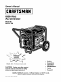
Owner's Manual
CRRFTSMRN°
6000 Watt
AC Generator
Model No.
580.327160
GENERATOR
CUSTOMER
HELPLINE
I_
HOURS:
Mon.-
CAUTION"
Fri. 8 a.m. to 5 p.m. (CT)
Before using this product,
read this manual and follow all Safety
Rules and Operating Instructions.
SEARS,
ROEBUCK
and CO.,
Hoffman
Estates,
IL 60179
Visit our Craftsman website: www.sears.com/craftsman
Part No. B2503
Draft
6 (8/28/2000)
•
•
•
•
•
Safety
Assembly
Operation
Maintenance
Parts
•
Espafiol
U.S.A.
WARRANTY ...................................
SAFETY RULES
ASSEMBLY
...............................
...................................
OPERATION ................................
MAINTENANCE
SPECIFICATIONS
2
TROUBLESHOOTING
3
SCHEMATIC
4
WIRING DIAGRAM .............................
5-11
............................
12-15
.............................
STORAGE ...................................
LIMITED WARRANTY
..........................
DIAGRAM .........................
REPLACEMENT
12
ESPANOL .................................
16
HOW TO ORDER PARTS ...............
PORTABLE
18
19
PARTS ......................
EMISSION CONTROL WARRANTY
FOR DELUXE
17
20-27
................
28
30-47
BACK PAGE
GENERATORS
SEARS warrants to the original purchaser that the alternator and engine for its portable generator will be free
from defects in materials or workmanship for the items and period set forth below from the date of original
purchase. This warranty is not transferable and applies only to portable generators driven by the Sears
warranted engine.
Alternator
Engine
CONSUMER*
2 years (2nd year parts only)
2 years (2nd year parts only)
COMMERCIAL*
1 year
1 year
* NOTE: For the purpose of this warranty "Consumer Use" means personal residential household and
emergency use by original purchaser, not to be used as a primary source of power. "Commercial Use" means all
other uses, including rental, construction, commercial, and income producing purposes. Once a generator has
experienced commercial use, it shall thereafter be considered a commercial use generator for the purpose of
this warranty.
During said warranty period, SEARS will, at its option, repair or replace any part which, upon examination by
SEARS, is found to be defective under normal use and service**. Starting batteries are not warranted by
SEARS. All transportation costs under warranty, including return to the factory if necessary, are to be borne by
the purchaser and prepaid by him. This warranty does not cover normal maintenance and service and does not
apply to a generator set, alternator or engine, or parts which have been subjected to improper or unauthorized
installation or alteration, misuse, negligence, accident, overloading, overspeeding, improper maintenance, repair
or storage so as, in SEARS's judgment, to adversely affect its performance and reliability.
** NORMAL WEAR: As with all mechanical devices, engines need periodic parts service and replacement to
perform well. This warranty will not cover repair when normal use has exhausted the life of a part or engine.
THERE IS NO OTHER EXPRESS WARRANTY. SEARS HEREBY DISCLAIMS ANY AND ALL
IMPLIED WARRANTIES, INCLUDING BUT NOT LIMITED TO THOSE OF MERCHANTABILITY
AND FITNESS FOR A PARTICULAR PURPOSE TO THE EXTENT PERMITTED BY LAW. THE
DURATION OF ANY IMPLIED WARRANTIES WHICH CANNOT BE DISCLAIMED IS LIMITED TO
THE TIME PERIOD AS SPECIFIED IN THE EXPRESS WARRANTY. LIABILITY FOR
CONSEQUENTIAL, INCIDENTAL, OR SPECIAL DAMAGES UNDER ANY AND ALL WARRANTIES
IS EXCLUDED.
Some states do not allow limitations on how long an implied warranty lasts, or the exclusion or limitation of
incidental or consequential damages, so the above limitations or exclusions may not apply to you. This warranty
gives you specific legal rights and you may also have other rights, which vary from state to state.
For service, see your nearest SEARS authorized warranty service facility. Warranty service can be performed
only by a SEARS authorized service facility. This warranty will not apply to service at any other facility. At the
time of requesting warranty service, evidence of original purchase date must be presented.
SEARS,
ROEBUCK
AND CO., Hoffman
Estates,
IL 60179 U.S.A
The engine exhaust from this product contains
chemicals known to the State of California
to cause cancer, birth defects,
or other reproductive harm.
,_
CAUTION!
Before allusing
thisRules
product,
manual
and follow
Safety
and read this
Operating Instructions.
DANGER! This generator is designed for
outdoor use only. Do Not use this generator
inside any building or enclosure including the
generator compartment of a recreational vehicle
(RV). Fire or an explosion may result. No user
performed modifications, including venting of
exhaust and/or cooling ventilation, will eliminate
the danger. Also, allow at least two feet of
clearance on all sides of the generator while
operating the unit.
CAUTION! Always disconnect spark plug wire
and place the wire where it cannot contact the
spark plug to prevent accidental starting when
setting up, transporting, adjusting or making
repairs to your generator.
•
The generator produces dangerously high voltage
that can cause extremely hazardous electrical
shock. Avoid contact with bare wires, terminals,
etc. Never permit any unqualified person to
operate or service the generator.
•
Never handle any kind of electrical cord or device
while standing in water, while barefoot or while
hands or feet are wet. Dangerous electrical shock
will result.
•
The National Electric Code requires the frame and
external electrically conductive parts of generator
be properly connected to an approved earth
ground. Local electrical codes may also require
proper grounding of the generator. Consult with a
local electrician for grounding requirements in your
area.
•
Use a ground fault circuit interrupter in any damp
or highly conductive area (such as metal decking or
steel work).
•
Do Not use worn, bare, frayed or otherwise
damaged electrical cord sets with the generator.
,_
•
Operate generator only on level surfaces and
where it will not be exposed to excessive moisture,
dirt, dust or corrosive vapors.
•
Gasoline is highly FLAMMABLE and its vapors are
EXPLOSIVE. Do Not permit smoking, open flames,
sparks or heat in the vicinity while handling
gasoline. Avoid spilling gasoline on a hot engine.
Comply with all laws regulating storage and
handling of gasoline.
•
Never add fuel while unit is running.
•
Do Not overfill the fuel tank. Always allow room for
fuel expansion. If tank is overfilled, fuel can
overflow onto a hot engine and cause FIRE or an
EXPLOSION.
•
Never store generator with fuel in tank where
gasoline vapors might reach an open flame or
spark or pilot light (as on a furnace, water heater or
clothes dryer). FIRE or EXPLOSION may result.
•
Generator exhaust gases contain DEADLY carbon
monoxide gas. This dangerous gas, if breathed in
sufficient concentrations, can cause
unconsciousness or even death. Operate this
equipment only in the open air where adequate
ventilation is available.
•
Allow at least 2 feet of clearance on all sides of
generator or you could damage the unit. Never
operate the unit inside any room or enclosure
where the free flow of cooling air into and out of the
unit might be obstructed. Review "Cold Weather
Operation" on page 10.
Never start or stop the unit with electrical loads
connected to receptacles AND with connected
devices turned ON. Start the engine and let it
stabilize before connecting electrical loads.
Disconnect all electrical loads before shutting down
the generator.
•
•
Do Not insert objects through units cooling slots.
•
Never operate generator:
in rain; in any enclosed compartment; when
connected electrical devices overheat; if electrical
output is lost; if engine or generator sparks; if
flames or smoke are observed while unit is running;
if unit vibrates excessively.
NOTE: Your generator is equipped with a spark
arrester muffler. The spark arrester must be
maintained in effective working order by the owner/
operator. In the State of California, a spark arrester is
required by law (Section 4442 of the California Public
Resources Code). Other states may have similar laws.
Federal laws apply on federal lands.
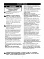
THIS
PERSONAL
IS THE INJURY
SAFETY HAZARDS.
ALERT SYMBOL.
OBEY ALL
IT ISSAFETY
USED TO
MESSAGES
ALERT YOU
THAT
TO POTENTIAL
FOLLOW THIS
SYMBOL TO AVOID POSSIBLE INJURY OR DEATH.
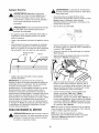
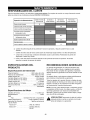
Your generator requires some assembly and is ready
for use only after it has been properly serviced with
the recommended oil and fuel.
If you have any problems with the assembly of
your generator, please call the generator helpline
at 1-800-222-3136.
IMPORTANT: Any attempt to run the engine before it
has been serviced with the recommended oil will result
in an engine failure.
REMOVE GENERATOR FROM
CARTON
Set the carton on a rigid flat surface with "this side
up" arrows pointing upward.
•
Carefully open the top flaps of the shipping carton.
•
If you plan to operate this unit in cold weather, read
"Cold Weather Operation" on page 9.
•
Slice two corners at one end of carton from top to
bottom and lay that side of carton down flat.
•
Remove all packing material, carton fillers, etc.
•
Remove the generator from the shipping carton.
CONTENTS
Check all contents. If any parts are missing or
damaged, call the generator helpline at
1-800-222-3136.
• The main unit
•
•
Battery charge cables
Screwdriver/spark plug wrench
Wheel
Owner's manual
Engine oil
2 locking plugs
Spare air filter element
Spare spark plug
Wheel Kit
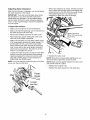
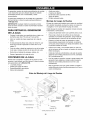
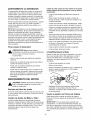
ASSEMBLING
THE WHEEL
KIT
You will need a socket wrench with 1/2" or 13mm
sockets to install the wheel kit.
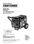
Install the wheel kit as follows (refer to illustration below):
•
CARTON
•
•
•
•
•
•
•
Place the generator on a hard flat surface. Place
temporary blocks under cradle to ease assembly.
•
Slide the axle through the holes in the brackets
provided on the generator cradle and then add the
two spacers on each protruding end of the axle.
• Slide a wheel and flat washer on each end of the
axle and insert retaining pin.
NOTE: Be sure to install wheel with raised hub
inboard. Each wheel can only be installed on one
specific side.
•
Attach the vibration mounts to the support leg with
two 30mm capscrews, M8 washers and M8 lock
nuts.
•
Attach the support leg with two 20mm capscrews
and two lock nuts. Remove the temporary blocks.
•
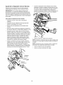
Attach the handle with four 45mm capscrews and
four lock nuts, on the unit's control panel end, as
shown.
Kit Assembly
View
handle
axle
45mm
capscrew
wheel
/
lock
/
washer
lock nut
/
wh_
spacer
support leg
/
capscrew
/
vibration mow
retaining
lock nut
flat washe_
30mm capscrew
pin
/
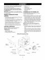
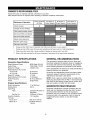
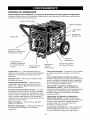
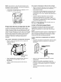
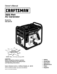
KNOW YOUR GENERATOR
Read the owner's manual and safety rules before operating your generator.
Compare the illustrations with your generator to familiarize yourself with the locations of various controls and
adjustments. Save this manual for future reference.
Fuel
Choke Lever
Air Cleaner
Run/Stop
Switch
Circuit Breakers
120 Volt AC, 30 Amp
Locking Receptacle
120/240 Volt AC, 30 Amp
Locking Receptacle
12 Volt DC
Receptacle
Spark Arrester Muffler
Grounding
Wing Nut
Idle Control
Switch
12 Volt DC Receptacle --This receptacle allows you
to recharge a 12 Volt automotive or utility style storage
battery with the battery charge cables provided.
120 Volt AC, 20 Amp, Duplex Receptacle -- May be
used to supply electrical power for the operation of
120 Volt AC, 20 Amp, single phase, 60 Hz electrical
lighting, appliance, tool and motor loads.
120 Volt AC, 30 Amp, Locking Receptacle -- May
be used to supply electrical power for the operation of
120 Volt AC, 30 Amp, single phase, 60 Hz electrical
lighting, appliance, tool and motor loads.
120/240 Volt AC, 30 Amp, Locking Receptacle -May be used to supply electrical power for the
operation of 120 and/or 240 Volt AC, 30 Amp, single
phase, 60 Hz electrical lighting, appliance, tool and
motor loads.
Air Cleaner -- Filters intake air as it is drawn into the
engine.
120 Volt AC, 20 Amp
Duplex Receptacle
Choke Lever--
Used when starting a cold engine.
Circuit Breakers (AC) -- Each receptacle is provided
with a "push to reset" circuit breaker to protect the
generator against electrical overload.
Fuel Tank -- Tank holds 7 U.S. gallons of unleaded
gasoline.
Grounding Wing Nut -- Provides a tie point for
grounding the unit.
Idle Control Switch -- The idle control runs the
engine at normal (high) speeds when there is an
electrical load present and runs the engine at idle
(low) speeds when a load is not present.
Run/Stop Switch -- Must be in "Run" position to start
engine. Set to "Stop" to stop a running engine.
Spark Arrester Muffler -- Muffler lowers engine
noise and is equipped with a spark arrester screen.
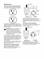
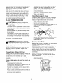
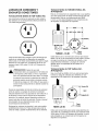
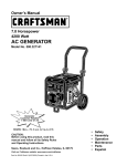
RECEPTACLES
120 Volt AC, 20 Amp Duplex
4-Wire Cord Set
Receptacle
240V -_
Use only high quality, well-insulated, extension cords
with the generator's 120 Volt electrical receptacles.
A NEMA L14-30 plug is required to use with the
240 Volt receptacle. Connect a suitable 4-wire cord set
to the plug and to the desired load. The cord set
should be rated for 250 Volt AC loads at 30 Amps (or
greater).
Each receptacle is protected against overload by a
single 20 Amp push-to-reset circuit breaker. Use each
receptacle to operate 120 Volt AC, single phase 60 Hz
electrical loads requiring up to 2,400 watts (2.4 kW) at
20 Amps of current.
_
120 Volt AC, 30 Amp Receptacle
Use a NEMA L5-30 plug with this receptacle. Connect
a 3-wire cord set rated for 125 Volt AC loads at
30 Amps to the plug.
3-Wire Cord Set
CAUTION!
each
receptacle
is rated
for 120 Volts Although
at 20 Amps
(2,400
watts or
2.4 kW), the generator is rated for a total of
6,000 watts. Powering loads that exceed the
wattage capacity of the generator can damage it
or cause serious injuries. See "Don't Overload
the Generator" on page 11.
Check the ratings of all extension cords before you
use them. Extension cord sets used should be rated
for 125 Volt AC loads at 20 Amps or greater for most
electrical devices. Some devices, however, may not
require this type of extension cord. Check the owner's
manuals of those devices for the manufacturer's
recommendations.
Keep extension cords as short as possible, preferably
less than 15 feet long, to prevent voltage drop and
possible overheating of wires.
120/240
Volt AC, 30 Amp Receptacle
This is a full capacity receptacle; it can take the
generator's full rated output from this sole
NEMA L14-30 outlet. The outlet is protected by two
30 Amp push-to-reset circuit breakers.
Neutral
C
120V
Hot
i_ i
-7L7 Ground
NEMA L5-30
(Green)
Use this receptacle to operate 120 Volt AC, 60 Hz,
single phase loads requiring up to 3,600 watts
(3.6 kW) of power at 30 Amps. The outlet is protected
by a 30 Amp push-to-reset circuit breaker.
12 Volt DC Receptacle
CONNECTING
This receptacle allows you to recharge a 12 Volt
automotive or utility style storage battery with the
battery charge cables provided.
•
Do Not connect 240 Volt loads to 120 Volt
receptacles.
•
Do Not connect 3-phase loads to the generator.
•
Do Not connect 50 Hz loads to the generator.
•
Let engine stabilize and warm up for a few minutes
after starting.
•
Plug in and turn on the desired 120 and/or 240 Volt
AC, single phase, 60 Hz electrical loads. DO NOT
OVERLOAD THE GENERATOR. Add up the rated
watts (or amps) of all loads to be connected at one
time. This total should not be greater than the rated
wattage/Amperage capacity of the generator. See
"Don't Overload the Generator" on page 11.
This receptacle can not recharge 6 Volt batteries and
can not be used to crank an engine having a
discharged battery. See the sections "Battery Safety"
and "Charging a Battery" on page 10 before
attempting to recharge a battery. This outlet is
protected by a 10 Amp self resetting circuit breaker.
HOW TO USE YOUR GENERATOR
If you have any problems operating your generator,
please call the generator helpline at 1-800-222-3136.
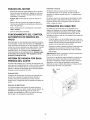
Grounding
the Generator
The National Electrical Code requires that the frame
and external electrically conductive parts of this
generator be properly connected to an approved earth
ground. Local electrical codes may also require proper
grounding of the unit. For that purpose, a grounding
wing nut is provided on the base of the cradle.
ELECTRICAL
BEFORE STARTING
GENERATOR
LOADS
THE
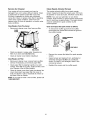
To operate the generator you will need to first add
engine oil and gasoline, as follows:
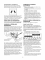
Add Engine Oil
NOTE: When adding oil to the engine crankcase in
the future, use only high quality detergent oil rated
with API service classification SF or SG SAE 30
weight. Use no special additives.
Select the oil's viscosity grade according to your
expected operating temperature. Do Not use
SAE 10W-40.
= 8I*]
_
_-,l_331=-T=j;
't';E._,rlv_5,_[
qIL-tvlv_,;{,]
°F -20
0
20 32 40
60
6
i'o 2'0
°C_ o -2'o -io
80
100
4'o
Temperature
Range ofExpectedUse
• Above 40°F, use SAE IOW-30 or SAE 30.
•
Grounding wing
Generally, connecting a No. 12 AWG (American Wire
Gauge) stranded copper wire to the grounding wing
nut and to an earth-driven copper or brass grounding
rod (electrode) provides adequate protection against
electrical shock. However, local codes may vary
widely. Consult with a local electrician for grounding
requirements in your area.
Proper grounding of generator will help prevent
electrical shock in the event of a ground fault condition
in the generator or in connected electrical devices.
Proper grounding also helps dissipate static electricity,
which often builds up in ungrounded devices.
Below 40°F,use synthetic
5W-20 or 5W-30.
Although multi-viscosity oils (5W30, 10W30, etc.)
improve starting in cold weather, these multi-viscosity
oils will result in increased oil consumption when used
above 32°F. Check your engine oil level more
frequently to avoid possible damage from running low
on oil.
•
Place generator on a level surface.
•
Clean area around yellow oil fill cap. Remove the
oil fill cap.
•
Slowly fill engine with oil through the oil fill opening
until the oil level is to the point of overflowing.
Install yellow oil fill cap and finger tighten securely.
•
•
Check engine oil level before starting each time
thereafter. If the oil level is below the point of
overflowing, fill to the proper level.
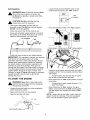
Locate the Idle Control ON/OFF switch on the
control panel and set it to the "OFF" position.
Add Gasoline
r
_
Never
fill fuel
indoors.
fill ARNING!
fuel tank when
engine
is tank
running
or hot.Never
Do Not light a cigarette or smoke when filling
the fuel tank.
,_
CAUTION!
Notfor
overfill
the fuel tank.
Always leave Do
room
expansion.
•
Use regular UNLEADED gasoline with the
generator engine. Do Not use premium gasoline.
Do Not mix oil with gasoline.
•
Clean area around fuel fill cap, remove cap.
•
Slowly add unleaded regular gasoline to fuel tank.
Be careful not to overfill. Allow about 1/2" of tank
space for fuel expansion, as shown here.
1/2" Air Space
IDLE
OFF
position
Place the Run/Stop switch in the "Run" position.
Tank
Fuel
•
•
Install fuel cap and wipe up any spilled gasoline.
IMPORTANT:
It is important to prevent gum deposits
from forming in fuel system parts such as the
carburetor, fuel hose or tank during storage. Alcoholblended fuels (called gasohol, ethanol or methanol)
can attract moisture, which leads to separation and
formation of acids during storage. Acidic gas can
damage the fuel system of an engine while in storage.
To avoid engine problems, the fuel system should be
emptied before storage of 30 days or longer. See
"Storage" on page 16. Never use engine or carburetor
cleaner products in the fuel tank as permanent
damage may occur.
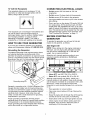
TO START THE ENGINE
_
•
Move engine Choke lever to "Full" choke position.
FULL
//
•
•
•
•
Open the fuel shut-off valve.
•
If engine fails to start, repeat all steps in "To
Start The Engine".
Move choke lever to "Run" position. If engine
falters, move choke lever to "Half" choke position
until the engine runs smoothly and then to "Run"
position.
NOTE: If engine fails to start after 3 pulls, check for
proper oil level in crankcase. This unit is equipped
with a Low Oil Shutdown System (see page 9).
FUEL TANK
Fuel Shutoff Valve-
•
If engine starts, skip the next step. If engine
fails to start, proceed to the next step.
Move choke lever to "Half" choke position, and pull
recoil twice.
•
ARNING!
Never
start orinto
stop
with
electrical
devices
plugged
theengine
receptacles
AND devices turned ON.
Unplug all electrical loads from units receptacles
before starting the engine.
Make sure the unit is in a level position.
Grasp the recoil handle and pull slowly until slight
resistance is felt. Then pull rapidly one time only to
start engine.
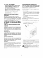
TO STOP THE ENGINE
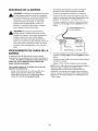
COLD WEATHER
•
Unplug all electrical loads from generator panel
receptacles. Never start or stop engine with
electrical devices plugged in and turned on.
Turn "Off" the Idle Control switch.
Under certain weather conditions (temperatures below
40°F [4°C] and a high dew point), your generator may
experience icing of the carburetor and/or the
crankcase breather system.
•
Let engine run at no-load for several minutes to
stabilize the internal temperatures of engine and
generator.
In an emergency, use the original shipping box as a
temporary shelter:
•
Cut off all flaps.
•
•
Move Run/Stop switch to "Stop" position.
Close the fuel valve.
•
Cut out one of the long sides of the box to expose
exhaust side of unit. Ensure a minimum of two feet
clearance between open side of box and nearest
object.
•
Cut appropriate slots to access receptacles and
clear handles.
•
Start unit, then place box over it.
•
OPERATING
CONTROL
AUTOMATIC
IDLE
This switch is designed to greatly improve fuel
economy. When this switch is turned "On", the engine
will only run at its normal high governed engine speed
when an electrical load is connected. When electrical
loads are removed, the engine will run at a reduced
speed. With the switch "Off," the engine runs
constantly at the normal high engine speed. Always
have the switch "Off" when starting and stopping
the engine.
OPERATION
IMPORTANT!: Remove shelter when temperature
above 40°F [4°C].
is
For a more permanent shelter, build a structure that
will enclose three sides and the top of the generator:
•
Make sure entire muffler-side of generator is
exposed. Note that your generator may appear
different from that shown here.
•
Ensure a minimum of two feet clearance between
open side of box and nearest object.
Restarting
•
Face exposed end away from wind and elements.
If you try to restart the engine within 10 seconds after
it shuts down, the engine may NOT start. The system
needs 5 to 10 seconds to reset.
•
Enclosure should hold enough heat created by the
generator to prevent problems.
LOW OIL PRESSURE
SYSTEM
SHUTDOWN
The engine is equipped with a low oil pressure
that shuts down the engine automatically when
pressure drops below 6 psi. If the engine shuts
by itself and the fuel tank has enough gasoline,
engine oil level.
sensor
the oil
down
check
Initial Start-up
A delay built in the low oil shutdown system allows oil
pressure to build during starting. The delay allows the
engine to run for about 10 seconds before sensing oil
pressure.
Sensing
Low Pressure
If the system senses low oil pressure during operation,
the engine shuts down. As the system shuts down, the
low oil light comes ON. However, once the engine has
stopped rotating, this light will go OFF.
If you do restart the engine after such a shutdown and
have not corrected the low oil pressure, the engine
runs for about 10 seconds as described above and
then stops.
,_
CAUTION!
NEVER
unit than
indoors;
Do Not
enclose generator
anyrun
more
shown.
Remove shelter when temperatures are above
40°F [4°C].
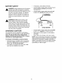
BATTERY
SAFETY
DANGER! Storage batteries give off explosive
hydrogen gas while recharging. An explosive
mixture will remain around the battery for a long
time after it has been charged. The slightest
spark can ignite the hydrogen and cause an
explosion. Such an explosion can shatter the
battery and cause blindness or other serious
injury.
•
If necessary, clean battery terminals.
•
Connect battery charge cable connector plug to
panel receptacle identified by the words
"12-VOLT D.C.".
•
Connect battery charge cable clamp with red
handle to the positive (+) battery terminal.
/_
_
DANGER! Do Not permit smoking, open
flame, sparks or any other source of heat
around a battery. Wear protective goggles,
rubber apron and rubber gloves when working
around a battery. Battery electrolyte fluid is an
extremely caustic sulfuric acid solution that can
cause severe burns. If spill occurs, flush area
with clear water immediately.
12 VOLT D.C.
RECEPTACLE
I
12 VOLT BATTERY
I
A BATTERY
•
Connect battery charge cable clamp with black
handle to the negative (-) battery terminal.
Your generator has the capability of recharging a
discharged 12 Volt automotive or utility style storage
battery. Do Not use the unit to charge 6 Volt
batteries. Do Not use the unit to crank an engine
connected to a discharged battery.
•
Start engine. Let the engine run while battery
recharges.
•
When battery has charged, shut down engine.
CHARGING
NOTE: Use an automotive hydrometer to test battery
state of charge and condition. Follow the hydrometer
manufacturer's instructions carefully. Generally, a
battery is considered to be at 100% state of charge
when specific gravity of its fluid (as measured by
hydrometer) is 1.260 or higher.
To recharge 12 Volt batteries, proceed as follows:
•
Check fluid level in all battery cells. If necessary,
add ONLY distilled water to cover separators in
battery cells. Do Not use tap water.
•
If the battery is equipped with vent caps, make
sure they are installed and are tight.
10
DON'T OVERLOAD
GENERATOR
THE
Overloading a generator in excess of its rated wattage
capacity can result in damage to the generator and to
connected electrical devices. Observe the following, to
prevent overloading the unit:
•
Add up the total wattage of all electrical devices to
be connected at one time. This total should NOT
be greater than the generator's wattage capacity.
•
The rated wattage of lights can be taken from light
bulbs. The rated wattage of tools, appliances and
motors can usually be found on a data plate or
decal affixed to the device.
WATTAGE
REFERENCE
•
If the appliance, tool or motor does not give
wattage, multiply volts times ampere rating to
determine watts (volts x amps = watts).
•
Some electric motors, such as induction types,
require about three times more watts of power for
starting than for running. This surge of power lasts
only a few seconds when starting such motors.
Make sure you allow for this high starting wattage
when selecting electrical devices to connect to your
generator. First, figure the watts needed to start the
largest motor. Add to that figure the running watts
of all other connected loads.
The Wattage Reference Guide is provided to assist
you in determining how many items your generator
can operate at one time.
GUIDE
Recreational/Home Uses
Tool/Appliance ............................
AM/FM clock radio .............................
Light bulb ...................................
Fan .......................................
20" color TV .................................
*Deep freezer ...............................
Personal computer and 15" monitor ..............
"1/3 hp furnace fan blower ......................
Microwave oven ..............................
"18 cu ft refrigerator ...........................
Sump pump ................................
Electric skillet ...............................
*½ hp water well pump .......................
"12,000 Btu window air conditioner ..............
Space heater ...............................
Electric water heater .........................
Professional/Contractor Uses
Tool/Appliance ............................
"1/3 hp airless sprayer .........................
3/8" hammer drill .............................
Variable speed Sawzall® ......................
½" power drill ...............................
Quartz-halogen work light .....................
Belt sander ................................
7 ¼" circular saw ............................
7 ¼" worm drive saw .........................
"1½ hp air compressor .......................
"10" power miter saw .........................
6" bench grinder ............................
*6" table planer .............................
"10" table/radial arm saw ......................
Wire feed welder ............................
*=allow 3 times listed watts for starting surge
Watts
50
100
200
400
500
800
800
800
800
1000
1250
1400
1400
1800
4000
11
Watts
600
600
960
1000
1000
1200
1500
1600
1800
1800
1800
1800
2000
2400
OWNER'S
RESPONSIBILITIES
Follow the hourly or calendar intervals, whichever occurs first.
More frequent service is required when operating in adverse conditions noted below.
Maintenance
Every 8 Hours
or Daily
Operation
Check oil level
25 Hours or
Every Season
50 Hours or
Every Season
100 Hours or
Every Season
X
Change oil and oil filters
Clean spark arrester screen
Service air filter pre-cleaner
Service air filter element
Adjust valve clearance
Replace spark plugs
Retorque head bolts
Change oil after first 8 hours of operation, then after every 50 hours or every season.
Change oil and oil filter every 25 hours when operating under heavy load or in high temperatures.
Clean more often under dirty or dusty conditions.
Replace air cleaner parts if very dirty.
Perform this task only after first 50 hours of operation. Head bolts will not need further retorquing.
PRODUCT
Generator
SPECIFICATIONS
6000 Watts (6.0 kW)
7500 Watts (7.5 kW)
120/240 Volts
Some adjustments will need to be made periodically to
properly maintain your generator.
25 Amperes
50 Amperes
12 Volts
10 Amperes
60 Hz at 3600 rpm
Single Phase
All service and adjustments should be made at least
once each season. Follow the requirements in the
"Maintenance Schedule" chart above.
NOTE: Once a year you should clean or replace the
spark plug and replace the air filter. A new spark plug
and clean air filter assure proper fuel-air mixture and
help your engine run better and last longer.
Specifications
Rated Horsepower ...........
Displacement ...............
Spark Plug
Type: ................
Set Gap To: ...........
Gasoline Capacity ............
Oil Type:
Above 32° F ..............
Below 32° F...............
RECOMMENDATIONS
The generator's warranty does not cover items that
have been subjected to operator abuse or negligence.
To receive full value from the warranty, the operator
must maintain generator as instructed in this manual.
Specifications
Rated Maximum Power ........
Surge Power ................
Rated AC Voltage ............
Rated Maximum AC Current
at 240 Volts ..............
at 120 Volts ..............
Rated DC Voltage ............
Rated Maximum DC Current ....
Rated Frequency ............
Phase .....................
Engine
GENERAL
11 at 3600 rpm
320 cc
GENERATOR
Champion RC12YC or
Equivalent
0.030inch (0.76mm)
7 U.S. gallons
Generator maintenance consists of keeping the unit
clean and dry. Operate and store the unit in a clean
dry environment where it will not be exposed to
excessive dust, dirt, moisture or any corrosive vapors.
Cooling air slots in the generator must not become
clogged with snow, leaves, or any other foreign
material.
SAE 30 or 10W-30
Synthetic 5W-20 or
5W-30
12
MAINTENANCE
Checkthe cleanliness
ofthe generator
frequentlyand • Coat gasket of new filter with engine oil. Turn filter
cleanwhendust,dirt,oil,moistureor otherforeign
clockwise until gasket contacts tightly with filter
substances
arevisibleon itsexteriorsurface.
adapter. Then tighten an additional 3/4 turn.
NOTE:DoNot usea gardenhoseto cleangenerator. • Fill oil sump with recommended oil (see page 7 for
Watercanentertheenginefuelsystemandcause
oil recommendations).
problems.Inaddition,ifwaterentersthegenerator
• Install the oil fill plug and tighten securely.
throughcoolingairslots,someofthewaterwillbe
• Wipe up any spilled oil.
retainedinvoidsandcracksofthe rotorandstator
windinginsulation.
Wateranddirtbuilduponthe
Clean/Replace
Spark Plug
generatorinternalwindingswilleventually
decrease
Change
the
spark
plug
every 100 hours of operation
the insulationresistance
ofthesewindings.
or once each year, whichever comes first. This will
help your engine to start easier and run better.
CLEAN THE GENERATOR
_
AUTION!
Never
insert
anyeven
objectif the
or tool
through
the air
cooling
slots,
engine
is not running.
•
Use a damp cloth to wipe exterior surfaces clean.
•
A soft bristle brush may be used to loosen caked
on dirt, oil, etc.
•
A vacuum cleaner may be used to pick up loose
dirt and debris.
•
Low pressure
used to blow
and openings
must be kept
air (not to exceed 25 psi) may be
away dirt. Inspect cooling air slots
on the generator. These openings
clean and unobstructed.
•
Clean area around spark plug.
•
Remove and inspect spark plug.
•
Check electrode gap with wire feeler gauge and set
spark plug gap to 0.030 inch (0.76mm) if
necessary.
•
Replace spark plug if electrodes are pitted, burned
or porcelain is cracked. Use a recommended
replacement plug.
ENGINE MAINTENANCE
,_
Retorque
DANGER!
When working
on wire
the generator,
always
disconnect
spark plug
from spark
plug and keep it away from spark plug.
Check
After the first 50 hours of operation, you must retorque
the head bolts to 6.9 kg.-m. (44 ft.-Ibs.).
Oil Level
IMPORTANT: If you feel uncomfortable about doing
this procedure or you don't have the proper tools,
please take your generator in to the nearest Sears
service center to have the head bolts retorqued. This
is a very important step to insure the longest life for
your engine.
Oil level should be checked prior to each use or at
least every 8 hours of operation. Keep oil level
maintained.
Change
Engine Oil and Oil Filter
NOTE: Only perform this adjustment after first
50 hours of operation. The head bolts will need no
further adjustment.
Change oil after first 8 hours of operation. Change oil
and oil filter every 50 hours thereafter. If you are using
your generator under extremely dirty or dusty
conditions, or in extremely hot weather, change oil
more often.
•
Change oil while engine is still warm from running, as
follows:
•
Clean area around oil drain plug.
•
Remove oil drain plug and oil fill plug and drain oil
completely into a suitable container.
•
When oil has completely drained, install oil drain
plug and tighten securely.
Place a suitable container beneath the oil filter and
turn filter counterclockwise to remove. Discard
according to local regulations.
•
Head Bolts
13
Torque sequence is as follows: A, B, C, D,
(alternating pattern).
Service
Air Cleaner
Clean Spark Arrester
Screen
Your engine will not run properly and may be
damaged if you run it using a dirty air cleaner. Clean
or replace the air cleaner paper filter once every
50 hours of operation or once a year, whichever
comes first. Clean or replace more often if operating
under dusty or dirty conditions. Clean foam precleaner every 25 hours of operation, or sooner under
dusty conditions.
The engine exhaust muffler has a spark arrester
screen. Inspect and clean the screen every 100 hours
of operation or once each year, whichever comes first.
Clean/Replace Foam Pre-cleaner
Clean and inspect the spark arrester as follows:
•
•
NOTE: If you use your generator on any forestcovered, brush-covered, or grass-covered unimproved
land, it must have a spark arrester. The spark arrester
must be maintained in good condition by the
owner/operator.
Remove air cleaner cover, then foam pre-filter.
PAPER
FILTER
To remove the muffler guard from the muffler,
remove the four screws that connect the guard to
the muffler bracket.
SPARK ARRESTE R
SCREEN
MUFFLER
HEAT SHIELD
FOAM
PRE-FILTER
•
Wash pre-cleaner in soapy water. Squeeze prefilter dry in clean cloth (Do Not twist).
•
Clean air cleaner cover before installing it.
Clean/Replace Air Filter
•
Remove air cleaner cover, remove foam pre-filter
(service if necessary), and remove paper filter.
•
Clean paper filter by tapping it gently on a solid
surface. If the filter is too dirty, replace it with a new
one. Dispose of the old filter properly.
•
Clean air cleaner cover then insert pre-cleaner into
cover. Next insert new paper filter into cover to
hold pre-cleaner in place. Assemble all of them to
the base of the air cleaner.
NOTE: If you need to order a new air filter, please call
1-800-366-PART.
14
•
Remove four screws that attach the spark arrester
screen.
•
Inspect screen and replace if torn, perforated or
otherwise damaged. Do Not use a defective
screen. If screen is not damaged, clean it with
commercial solvent.
•
Reattach the screen and the muffler guard.
Adjusting
When valve clearance is correct, hold the pivot ball
stud in place with the allen wrench and tighten the
rocker arm jam nut to 165-183 inch-pounds torque.
After tightening the jam nut, recheck valve
clearance to make sure it did not change.
Valve Clearance
After the first 50 hours of operation, you should adjust
the valve clearance in the engine.
IMPORTANT: If you feel uncomfortable about doing
this procedure or you don't have the proper tools,
please take your generator in to the nearest Sears
service center to have the valve clearance adjusted.
This is a very important step to insure the longest life
for your engine.
To adjust valve clearance:
•
Make sure the engine is at room temperature.
•
Make sure that the spark plug wire is removed from
the spark plug and out of the way.
Remove the breather tube from the valve cover.
•
•
Remove the four screws holding the valve cover
with a #2 or #3 phillips screwdriver.
•
Make sure the piston is at Top Dead Center (TDC)
of its compression stroke (both valves closed). To
get the piston at TDC, pull on the recoil handle
slowly watching the piston through the spark plug
hole. As you pull on the recoil handle, the piston
should move up and down. The piston is at TDC
when it is up as high as it can go.
tighten Jam Nut to
165 to 183 inch-pounds
(19-21 N-m)
\
•
Loosen the rocker arm jam nut. Use an 8 mm allen
wrench to turn the pivot ball stud while checking
clearance between the rocker arm and the valve
stem with a feeler gauge. Correct clearance is
0.002-0.004 inch (0.05-0.1 mm).
NOTE: You must hold the rocker arm jam nut in place
as you turn the pivot ball stud.
• Reattach the valve cover.
NOTE: Start all four screws before tightening or you
will not be able to get all the screws in place.
NOTE: Make sure the gasket between the valve cover
and cylinder head is in place.
Feeler
Gauge
Allen Wrench
0
Loosen
Jam Nut
15
•
Reattach the breather tube.
•
Reattach the spark plug wire to the spark plug.
GENERAL
Engine
The generator should be started at least once every
seven days and allowed to run at least 30 minutes. If
this cannot be done and you must store the unit for
more than 30 days, use the following information as a
guide to prepare it for storage.
Change Oil
While engine is still warm, drain oil from crankcase.
Refill with recommended grade.
Long Term Storage
•
Remove spark plug and pour about 1/2 ounce
(15ml) of engine oil into the cylinder. Cover spark
plug hole with rag. Pull starter handle slowly to
distribute oil.
•
Install spark plug. Do Not connect spark plug wire.
_
Oil Cylinder Bore
Instructions
ARNING!
store engine
fuel in
tank
indoors orNEVER
in enclosed,
poorly with
ventilated
areas where fumes may reach an open flame,
spark, or pilot light as on a furnace, water
heater, clothes dryer, or other gas appliance.
_
It is important to prevent gum deposits from forming in
essential fuel system parts, such as the carburetor,
fuel filter, fuel hose or tank during storage. Also,
experience indicates that alcohol-blended fuels (called
gasohol, ethanol or methanol) can attract moisture,
which leads to separation and formation of acids
during storage. Acidic gas can damage the fuel
system of an engine while in storage.
Generator
_
•
•
•
Clean the generator as outlined in "Clean the
Generator" on page 13.
•
Check that cooling air slots and openings on
generator are open and unobstructed.
Other Storage
To avoid engine problems, the fuel system should be
emptied before storage of 30 days or longer. Follow
these instructions:
Protect
AUTION!
spray
from spark plug hole
when
crankingAvoid
engine
slowly.
Fuel System
ARNING!away
Drain
intoflame.
approved
container
outdoors,
fromfuel
open
Be sure
engine is cool. Do Not smoke.
Remove all gasoline from the fuel tank to prevent
gum deposits from forming on these parts and
causing possible malfunction of engine.
•
Do Not store gasoline from one season to another.
•
Replace your gasoline can if it starts to rust.
Contaminated gasoline will cause engine problems.
•
If possible, store your unit indoors and cover it to
give protection from dust and dirt. BE SURE TO
EMPTY THE FUEL TANK.
•
Cover your unit with a suitable protective cover that
does not retain moisture.
_
Run engine until engine stops from lack of fuel.
•
16
Tips:
ANGER!
NEVER area
coverare
your
generator while
engine
and exhaust
warm.
Store generator in clean, dry area.
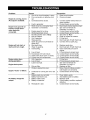
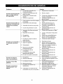
Problem
Engine is running, but no
AC output is available.
Engine runs good at noload but "bogs down"
when loads are
connected.
Engine will not start; or
starts and runs rough.
Engine shuts down
during operation.
Cause
1. One of the circuit breakers is open.
2. Poor connection or defective cord
set.
3. Connected device is bad.
Correction
1. Reset circuit breaker.
2. Check and repair.
4.
1.
2.
Fault in generator.
Short circuit in a connected load.
Generator is overloaded.
4.
1.
2.
3.
4.
1.
2.
3.
4.
5.
3.
4.
1.
2.
3.
4.
5.
6.
7.
8.
Engine speed is too slow.
Shorted generator circuit.
Run/Stop Switch set to "Stop".
Dirty air cleaner.
Out of gasoline.
Stale gasoline.
Spark plug wire not connected to
spark plug.
Bad spark plug.
Water in gasoline.
Overchoking.
9.
10.
11.
12.
1.
2.
1.
Low oil level.
Excessively rich fuel mixture.
Intake valve stuck open or closed.
Engine has lost compression.
Out of gasoline.
Low oil level.
Load is too high.
2.
1.
Dirty air filter.
Choke is opened too soon.
2.
1.
2.
3.
4.
Carburetor is running too rich or too
lean.
Battery posts are corroded.
Battery fluid level is low.
Battery cable is bad.
Battery is defective.
5.
Receptacle is bad.
Engine lacks power.
Engine "hunts"
or falters.
No battery charge DC
output.
3.
6.
7.
8.
Replace spark plug.
Drain fuel tank; fill with fresh fuel.
Open choke fully and crank
engine.
9. Fill crankcase to proper level.
10. Contact Sears service facility.
11. Contact Sears service facility.
12. Contact Sears service facility.
1. Fill fuel tank.
2. Fill crankcase to proper level.
1. See "Don't Overload the
Generator" on page 11.
2. Replace air filter.
1. Move choke to halfway position
until engine runs smoothly.
2. Contact Sears service facility.
1.
2.
3.
4.
5.
17
Connect another device that is in
good condition.
Contact Sears service facility.
Disconnect shorted electrical load.
See "Don't Overload the
Generator" on page 11.
Contact Sears service facility.
Contact Sears service facility.
Set switch to "Run".
Clean or replace air cleaner.
Fill fuel tank.
Drain fuel tank; fill with fresh fuel.
Connect wire to spark plug.
Clean battery posts.
Add distilled water to battery.
Replace cable.
Check battery condition; replace if
defective.
Contact Sears service facility.
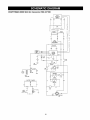
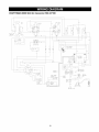
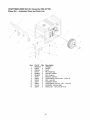
CRAFTSMAN
6000 Watt AC Generator
580.327160
REGULATOR
_OARD
POWER
1
4_
2
6
S
N
U
B
B
E
R
FI ELD
F
E
13
11
I
22
InLE
44
G
A
T
E
___
s
I
G
N
A
L
TRANSFORMER
-,1-_d
_
CONTROL
155
__i
YEL
_
\,'_/
"0_
1
156
22
_ I ii_EiL
ILGRNI
/
I
I
44
/
I
_o;
[--_IIE
iL_N
_
;L_U_
* _1_
_Wi'TOH
EN[)G,I C
I 1
_
I
--
IGNITION
120V
/
20A
2_
BATTERY
66
/
_11A_
GRN
c.
B1
CHARGE
55
I
77
l__p
_ I
13
55
OR2EL
T_O2oAO------11B
--
I
I
C,I],
11A
15
ov
30A
18
'
CRAFTSMAN
o
6000 Watt AC Generator
580.327160
18ov
20A
44A
4_
2C
22_!
SR[3KEN
L
[3FF
44
I
GRN
NUT
KNGZNK
19
DN
SLDCK
IIA
ii
11
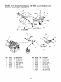
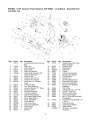
CRAFTSMAN
6000 Watt AC Generator
Main Unit m Exploded
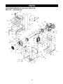
580.327160
View
56
48
(,
900
10
46
51
55
31
31
43
31
14
13
29
15
32
_36
41
1
22
39
3O
26
28
2O
33
19
62
31
62
61
20
59
31
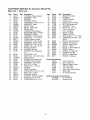
CRAFTSMAN
6000 Watt AC Generator
Main Unit m Parts List
Item
2
3
4
5
6
7
8
9
10
11
12
13
14
15
16
17
18
19
20
21
22
24
25
26
27
28
29
30
31
32
33
34
35
36
37
38
39
40
Part #
92247
92678G
65791
96796
28092
92680G
B92039
B2505
77026
66825C
65795
67022
84132
86308A
B4871
66849A
66386
66849
74908
82857
22129
22769
Qty.
1
1
1
1
1
1
1
2
1
1
1
1
1
4
1
1
1
2
4
4
14
1
86292
1
86494
1
14353621 1
26850
2
83083
1
92630A
1
25244
12
40976
2
B92432
1
92609
2
22531
2
81917
1
B92531
1
B92731
1
22142
2
66476
2
580.327160
Description
HOUSING, Engine Adapter
ASSEMBLY, Rotor
BEARING
WASHER, M8 Flat
CAPSCREW, 5/16-24 x 9-1/4
ASSEMBLY, Stator
SHIELD, Heat
DECAL, Heat Shield
DECAL, Data
CARRIER, Rear Bearing
RECTIFIER, Battery Charge
GROMMET, Rubber
ASSEMBLY, Power Module
SCREW, M6 - 1 x 145 mm
COVER, Bearing Carrier
SCREW, M5 - 0.8 x 20 mm
ASSEMBLY, Brush Holder
SCREW, M5 - 0.8 x 16 mm
SCREW, M5 - 0.8 x 10 mm
MOUNT, Vibration
WASHER, M8 Lock
WASHER, #10 Shakeproof
Int.
CAPSCREW, #10
SCRW, M6 - 1.0 x16mm Wing
WIRE, Ground
WASHER, M6 Shakeproof
SCREEN, Spark Arrester
ASSEMBLY, Control Box
NUT, 5/16- 18 Hex
SCREW, M8 - 1.25 x 20
CRADLE
MOUNT, Vibration
CAPSCREW, 5/16-18 x 1-3/4"
PIN, 4 mm x 10 Roll
SUPPORT, Engine
SUPPORT, Engine & Muffler
SCREW, 5/16 - 18 x 3/4"
CAPSCREW, M6 -1.0 x 12
Item
41
42
43
44
45
46
47
48
49
50
51
52
53
55
Part #
92532
A7433
90239
80270
78299
77395
83465
57058
B4363
85000
92982
B1695
92665
86307
Qty.
1
1
1
1
1
4
4
4
1
1
1
1
1
4
56
57
58
59
60
61
62
63
64
900
93826
56893
B96068
96409
B4901
B4986
B2153
22473
B2506
NSP
1
5
1
1
1
1
6
4
1
1
Parts Not Illustrated
1
B2503
AB3061
2
65787
1
43438
1
37806
1
84882
1
72347
1
1
73111
Optional
21
Accessories
09-32688
1
09-32785
1
Description
BRACKET, Muffler
MUFFLER
GASKET, Muffler
VALVE, Tank
BUSHING, Tank Plastic
NUT, M6 Flange Lock
GROMMET, Tank
HHCS, M6- 1.0 x 55
CAP, Fuel Gauge
CLIP, Insulation
DECAL, Danger
TANK, Fuel 7-Gal
INSULATION, 2- 1/4" Thick
CAPSCREW, 5/16-24 x 3/4"
SEMS
DECAL, Start Instructions
SCREW, #10-24 x 1/2"
SHIELD, Heat Muffler
DECAL, "1-800..."
DECAL, 1-800-4-MyHome
DECAL, Ground
SCREW, #12 Self Drill
WASHER, Flat M6
DECAL, Control Panel
ENGINE, Craftsman
Owner's Manual
28 oz. Engine oil
Battery Charge Cables
240 V 30A Plug
120 V 30A Plug
Spark Plug Wrench/Driver
Spark Plug
Air Cleaner Element
Not Shown
Cord Wrap Kit
Storage Cover
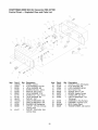
CRAFTSMAN
Control
6000 Watt AC Generator
Panel m Exploded
580.327160
View and Parts List
19
'\\\\
21
20
19
\
k
25
\\\\\
8
10
\
6
10
_
11
11
13
16
\
\
22
8
24
18
<
23
7
/
2
/
5
Item
1
2
3
4
5
6
7
8
9
10
11
12
13
14
PaN #
A92070
23897
49226
91526
82538
82881
43181
43182
90418
75207A
75207
23365
68868
43437
4
Qty.
1
4
4
4
1
4
4
4
1
2
2
6
1
1
\\\\
3
Description
PANEL, Control
FLAT WASHER, #10 M5
LOCK WASHER, M5
SCREW, M5-0.8 x 12mm
SWITCH, Idle Control
LOCK WASHER, 7/16"
SCREW, M3 - 0.5 x 10mm
LOCK WASHER, M3
OUTLET, 12V
CIRCUIT BREAKER, 30A
CIRCUIT BREAKER, 20A
WASHER, #8 Shakeproof
OUTLET, 120 Volt, 30 Amp
Locking Type
OUTLET, 120V/240V, 30A
Locking Type
22
Item
15
16
17
18
19
20
21
22
PaN #
68759
43180
22264
51715
64526
83970
64525
87962
Qty.
1
6
6
6
8
1
4
1
23
24
25
26
84335
84134
B92069
84028
1
1
1
1
Description
OUTLET, 120V, 20A Duplex
FLAT WASHER, M4
LOCK WASHER, #8 M4
NUT, M4-0.7 Hex
SCREW, #6-32 x 3/8"
BOARD, System Control
STAND-OFF, 3/4" Hex
CIRCUIT BREAKER. 12V,
10A (auto)
ASSEMBLY, Wire Harness
GROMMET, Rubber Conn.
BOX, Control Panel
TRANSFORMER, Idle Control
CRAFTSMAN
Wheel
Kit --
6000 Watt AC Generator
Exploded
580.327160
View and Parts List
s
Item
1
2
3
4
5
6
7
8
9
10
11
12
13
Pa_ #
Qty.
B93393A
1
93682
2
93693A
1
87005
2
B93685
2
B93696
1
27007
2
42909
2
52858
8
22247
2
39253
2
22145
2
39287
4
Description
HANDLE
WHEEL
AXLE
PIN, Retaining
SPACER, Wheel
LEG, Support
MOUNT, Vibration
CAPSCREW, Hex Hd. M8 - 1.25 x 30
NUT, Lock M8
WASHER, Wheel
CAPSCREW, Hex Hd. - M8 - 1.25 x 20
WASHER, Vibration Mtg.
HHCS, M8- 1.25 x 45 GR 10.9
23
ENGINE, 11 HP, Generac Power Systems,
GovernorExploded View and Parts List
EHF 00945 - Low Oil Shutdown
7
And
13
14
15
White
/
8
16
1
9
"_
10
\15
White
_ _From
-J Control Panel
4
To Oil Switch
21
25
23
2O
/
32
9
27
28
31
Item
7
8
9
10
12
13
14
15
16
Part #
78653
85272
93104
93611
84329
92981
22097
92079
84542
Qty.
1
1
1
1
1
1
2
2
1
Item
20
21
23
24
25
27
28
29
30
31
32
Description
Run/Stop Switch
Led Assembly
L.O.S. Decal
Black Sleeving
3 Pin Male Hsg.
Wire Asm.
M6 Lockwasher
M6 x 30 Taptite
Ignition Coil
24
Part #
72347
72734
83502
83512
73100
83503
73101
72735
72789
83782
66311
Qty.
1
1
1
2
1
1
1
1
1
1
1
Description
Sparkplug
Governor Lever
Adjust Screw
M8 x 15 Taptite
60Hz Gov. Spring
M5 Lock Nut
Governor Bracket
Governor Rod
Anti-Lash Spring
Idle Control ASM
M8-1.25 Jam Nut
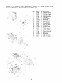
ENGINE, 11 HP, Generac Power Systems, EHF 00945 - Oil Filter & Switch,
Starter and Flywheel - Exploded View and Parts List
Item
2
3
4
5
6
78
79
80
81
82
83
84
85
86
87
88
89
90
91
92
93
5
/
2
/
/
/
6
78
/
/
79
/
/
/
/
Part #
86999
94683
49821
60108
70185
82774
77147A
67198N
67890
88433
45756
78609
73104A
92437
88434
66476
96195
96196
73116C
81668
83512
80
/
/
/
/
/
/
81
91
92
88
85
/
/
/
89
\\\\\
/
/
/
/
/
/
83
84
'\
\\\\
82
86
85
"87
\\\\
\
83
25
/
92
Qty.
1
1
2
1
1
1
1
1
1
1
7
2
1
1
1
4
1
1
1
5
1
Recoil
Description
Oil Filter Gasket
Oil Filter Adapter
M8 x 30 SHCS
Oil Press Switch
Oil Filter
Woodruff Key
Flywheel
Conical Washer
M16 Hex Nut
Top Wrapper
M6 x 10 Taptite
Cover Bolt
Air Box Cover
Blower Housing
Lower Wrapper
M6 x 12mm Capscrew
Recoil Assembly
Recoil Cup
Backplate
M6 x 10 HHCS
M8 x 15 Taptite
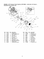
ENGINE, 11 HP, Generac Power Systems,
Exploded View and Parts List
EHF 00945 - Carburetor,
Air Cleaner
-
34
/
40
33
6O
42
43
45
44
,34¸
38
41
4O
33
_
46
47
@
48
5O
35
51
49
37
/
45
37
38
Item
31
32
33
34
35
36
37
38
39
40
41
42
Part #
72745
91039
40945
81647
66476
91028
22097
49813
90970
93873
91204
89228
Qty.
1
1
2
2
2
1
3
2
1
2
1
1
Item
43
44
45
46
47
48
49
50
51
60
61
62
Description
Breather Hose
Head/Manifold Gasket
M6 x 20 SHCS
Carb. Bolt
M6 x 12 HHCS
K Adapter
M6 Lock Washer
M6 Hex Nut
Carb./Airbox Gasket
M6 Ribbed Lockwasher
Spitback Plate
Carb/Manifold Gasket
26
Part #
91187A
73108A
49811
59635
73111
81646
83504
47411
90827
30340
48031C
73104B
Qty.
1
1
4
1
1
1
1
2
1
12"
1
1
Description
Nikki Carb.
Air Cleaner Base
M6 Flatwasher
#8 x 3/8 Plastite
Air Filter
Pre-cleaner
Choke Knob
M6 x 16 HHCS
Brkt. Air Box
1/4" ID Hose
Hose Clamp
Air Cleaner Cover
ENGINE, 11 HP, Generac
and Parts List
Power Systems,
EHF 00945 - Long Block - Exploded
1
\
25
52_
46
View
14
"%.
5
h
12_
56
\\\
23"
26 _/
t
22
43
54
53
/
42
7
2O
51
29
_47
37
58
/
59
19
\\\\\_112
\
41
51
\
47
52
10
54
55
Item
1
Part #
71978
Qty.
1
2
3
4
5
6
71980
71977
76339
71983
78666A
1
1
1
2
1
7
8
9
10
83948
78658
78659
88261C
1
1
2
1
12
13
14
15
19
20
21
22
23
24
25
26
27
28
29
30
72655
83912
78645
76365
83932
76701
21713A
78691
83918
76362
76361
88260B
86514
91308
86025
84430
2
1
1
1
1
1
1
1
1
1
1
1
2
2
1
1
21
Description
Connecting Rod with Cap and
Bolt
Piston Pin
Piston Ring Set
Piston (410)
Piston Pin Retainer
Crank Shaft Assembly With
Gears (Small Taper)
Governor Arm
Governor Arm "R" Pin
Governor Arm Washer
Crankcase H.S. W/Taper
Plugs
Crankshaft Seal
Gov. Gear Assembly
Governor Retainer ("C" Ring)
Governor Spool
Camshaft Assembly
Crankcase Gasket
Cylinder Head Gasket
Oil Pressure Relief Cover
Press. Relief Spring
Press. Relief Ball
Thrust Washer
Gear Cover Assy.
Valve Spring Retainer
Valve Spring
Gerotor Set
Balancer
Item
31
27
Part #
21714
Qty.
1
32
33
34
35
36
37
38
39
40
41
42
43
86516
86517
88396B
83897
77158
71987
72694
83907
72696
78694
21742
83938
1
1
2
2
1
1
2
2
2
1
4
1
44
46
47
48
50
51
76329
86254
26925
74908
86515
78606
1
1
2
1
4
4
52
A1442
8
53
54
55
78672
89673
B2104
21948B
1
2
0
0
Description
Cylinder Head With Valve
Seats & Guides
Exhaust Valve
Intake Valve
Push Rod
Tappet
Oil Pick-Up Assembly
Rocker Cover Gasket
Pivot Ball Stud
Rocker Arm
Jam Nut (Rocker Arm)
Push Rod Guide Plate
M10 x 108 Head Bolt
Rocker Cover Breather
Assembly
Oil Fill Plug
O-Ring 17.8 I.D. x 2.4 THK.
3/8" NPT Pipe Plug
M5-0.8 x 8mm Screw
Valve Spring Keeper
M6-1 x 12mm PH Screw and
Lockwasher
Hex Head flange Bolt M8 1.25
x 42mm
Valve Stem Seal
Valve Spring Washer
Wear Washer
All items in Long Block
Assembly
Your Warranty
If you have any questions regarding your warranty rights
and responsibilities, your should contact your nearest
authorized service center or call Sears at
1-800-473-7247.
Rights and Obligations
The California Air Resources Board ("CARB") and Sears
Roebuck and Co., USA, are pleased to explain the Emission
Control System Warranty on your model year 2000 and later
small off-road engine (engine). In California, new engines
must be designed, built and equipped to meet the State's
stringent anti-smog standards. Sears must warrant the
emission control system on your engine for the periods of
time listed below provided there has been no abuse, neglect,
or improper maintenance of your engine.
Warranty
Any warranted part which is not scheduled for replacement
as required maintenance, or which is scheduled only for
regular inspection to the effect of "repair or replace as
necessary" shall be warranted for 2 years. Any warranted
part which is scheduled for replacement as required
maintenance shall be warranted for the period of time up to
the first scheduled replacement point for that part.
Your emission control system includes parts such as the
carburetor and the ignition system.
Where a warrantable condition exists, Sears will repair your
engine at no cost to you. Expenses covered under under
warranty include diagnosis, parts, and labor.
Manufacturer's
Warranty
Diagnosis
The owner shall not be charged for diagnostic labor which
leads to the determination that the warranted part is
defective if the diagnostic work is performed at an approved
Sears service center.
Coverage
The model year 2000 and later engines are warranted for
two years. If any emission related part on your engine (as
listed below) is defective, the part will be repaired or
replaced by Sears.
Owner's
Warranty
Consequential
Responsibilities
WHAT IS NOT COVERED
All failures caused by abuse, neglect, or improper
maintenance are not covered.
Add-on
If you have any questions regarding your warranty rights and
responsibilities, you should contact your nearest authorized
service center or call Sears at 1-800-473-7247.
Where
If you have any questions regarding your warranty rights and
responsibilities, you should contact your nearest authorized
service center or call Sears at 1-800-473-7247.
Date
Service
Maintenance,
Replacement
Emission Related Parts
and Repair of
Any Sears approved replacement part used in the
performance of any warranty maintenance or repair on
emission related parts will be provided without charge to the
owner if the part it under warranty.
of Coverage
Sears warrants to the initial owner and each subsequent
purchaser that the engine is free from defects in materials
and workmanship which cause the failure of a warranted
part for a period of two years.
Emission
Control Warranty
Parts List
1. Carburetor Assembly
WHAT IS COVERED
•
to Get Warranty
Warranty services or repairs shall be provided at all Sears
authorized service centers.
The warranty period begins on the date the engine is
delivered.
Repair or Replacement
Parts
How to File a Claim
You are responsible for presenting your engine to a Sears
authorized repair center as soon as a problem exists.
Warranty repairs should be completed in a reasonable
amount of time, not to exceed 30 days.
Length
or Modified
The use of add-on or modified parts can be grounds for
disallowing a warranty claim. Sears is not liable to cover
failures of warranted parts caused by the use of add-on or
modified parts.
As the engine owner, you should be aware that Sears may
deny you warranty coverage if your engine or a part of it has
failed due to abuse, neglect, improper maintenance,
unapproved modifications, or the use of parts not made or
approved by the original equipment manufacturer.
Commencement
Damages
Sears may be liable for damages to other engine
components caused by the failure of a warranted part still
under warranty.
As the engine owner, you are responsible for the
performance of the required maintenance listed in this
owners manual. Sears recommends that you retain all
receipts covering maintenance on your engine, but Sears
cannot deny warranty solely due for the lack of receipts or
for your failure to ensure the performance of all scheduled
maintenance.
Warranty
Period
2.
Ignition System
a.
of Parts
Spark Plug, covered up to maintenance
b.
Ignition Module
3. Crankcase Breather Tube
Repair or replacement of any warranted part will be
performed at no charge to the owner at an approved
Sears service center.
4.
28
Exhaust Manifold
schedule.
29
GARANTIA..............................
REGLASDESEGURIDAD..................
ENSAMBLAJE
............................
FUNClONAMIENTO
.....................
MANTENIMIENTO
......................
GARANTIA
LIMITADA
30
31
32
33-39
40-43
ESPECIFICACIONES
DELPRODUCTO
........ 40
ALMACENAMIENTO
.......................
44
DIAGNOSTICOS
DEAVERiAS...............
45
GARANTIA
DEEMISIONES
...............
46-47
PARTES/SERVICIO
............
ULTIMAP,_,GINA
DE GENERADOR
PORTATILE
CRAFTSMAN
SEARS garantiza al comprador original que el alternador y el motor para su generador portatil estaran libres de defectos en
los materiales o la mano de obra para las piezas y el periodo establecido a partir de la fecha de compra original. Esta
garantia no es transferible y se aplica Qnicamente a los generadores portatiles impulsados por el motor garantizado
GN Seria de Sears.
Alternador
Motor
Consumidor*
2 ahos
2 ahos
Comercial*
1 aho
1 aho
*NOTA: Para el prop6sito de esta garantia "Uso de Consumidor" quiere decir uso dom6stico de residencia personal por el
comprador original. "Uso Comerciar' quiere decir todos los otros usos, incluyendo alquiler, construcci6n, comercial y
prop6sitos que producen ganancia. Una vez que un generador ha experimentado uso comercial, de alli en adelente sera
considerado como un generador de uso comercial para los prop6sitos de esta garantia.
Durante dicho periodo de grantia, SEARS reparara o remplazra a su opci6n cualquier pieza la cual, al ser examinada por
SEARS, se encuentre que esta defectiosa bajo uso y servicio normales**. Las baterias de arranque no estan garantizadas
por SEARS. Todos los costos de tranporte bajo la garantia, incluyendo la devoluci6n a la fabrica si fuera necesario, seran
cargados al comprador y prepagados por 61. Esta grantia no incluye el mantenimiento y servicio normal no se aplica a un
conjunto de generador, alternador o motor, o las piezas que han sido sujetas a instalaci6n a alteraci6n inadecuadads o
desautorizadas, abuso, negligencia, accidentes, sobrecarga, velocidad excesiva, mantenimiento, reparciones o
almacenamiento inadecuados, de modo que, en la opini6n de SEARS, afecten adversamente su rendimiento y confiabilidad.
**Degaste Normal: Como con todos los aparatos el6ctricos, los motores necesitan servicio y reemplazo peri6dico para que
den buen rendimiento. Esta garantia no cubrira reparaci6n cuando el uso normal ha agotado la duraci6n de una pieza o de
un motor.
No hay ninguna otra garantia expresada. SEARS por este medio desconoce cualquiera y todas las grantias implicadas,
incluyendo pero no limitandose a aquellas de mercantibildad y adaptaci6n para un proposito particular, en la proporci6n
permitada por la ley. La duraci6n de cualquier garantia implicada la cual no puede ser desconocida se limita al periodo de
teimpo segt_n se especifica en la garantia expresada. La responsabilidad por daSos de consequencia, accidentales o
especiales bajo cualquiera o todas las garantias se excluye. Algunos estados no permiten limitaciones sobre cQanto tiempo
una garantia implicada dura, o la exclusion o limitaci6n de daSos accidentales o de consecuencia, de manera que las
limitaciones o exclusiones mencionadas anteriormente pueden no aplicar para usted. Esta garantia le da derechos legales
especificos y usted tambi6n puede tener otros derechos, los cuales varian de estado a estado.
Para servicio, p6ngase en contaco la instalaci6n de servicio de garantia autorizada mAs cercana de SEARS. El servicio de
garantia puede ser Ilevado a cabo solamente por una instalaci6n de servicio autorizado de SEARS. Esta garantia no se
aplica al servicio dado en ninguna otra instalaci6n. En el momento de solicitar servico de grantia, se debe presentar
evidenca de la fecha de compra original.
SEARS,
ROEBUCK
AND CO., D/817 WA, Hoffman
30
Estates,
IL 60179
El escape del motor de este producto contiene
PRECAUCION!
Siempre
el alambre
de
la bujia y col6quelo
dondedesconecte
no pueda entrar
en
contacto con la bujia, para evitar el arranque
accidental durante la instalaci6n, transporte, ajuste o
reparaci6n de su generador.
iPELIGRO!
Este generador esta diseSado para uso
en exteriores Qnicamente. No use este generador en
el interior de ninguna edificaci6n o recinto cerrado,
incluyendo el compartimiento para generador de un
vehiculo recreacional (VR). Podrian ocurrir incendios
o explosiones. Las modificaciones realizadas por el
usuario, incluyendo ventilaci6n del escape y/o
ventilaci6n de enfriamiento, no eliminaran el peligro.
Tambi6n, permita que exista al menos dos pies de
distancia alrededor del generador, incluso cuando
est6 operando la unidad en exteriores.
&
PRECAUCION!
manual y de
siga
todas las
Reglas
de SeguridadLea
e este
Instrucciones
Operaci6n
antes de usar este producto.
•
El generador produce un voltaje muy alto, el cual puede
ocasionar descargas el6ctricas extremamente
peligrosas. Evite el contacto con terminales, alambres
pelados o sin recubrimiento, etc. Nunca permita que
personas no calificadas operen o proporcionen servicio
al generador.
•
Nunca manipule dispositivos o cordones el6ctricos
cuando se encuentre parado en agua, descalzo o con
los pies o las manos mojadas.
•
El C6digo EI6ctrico Nacional exige que el bastidor y las
partes externas conductoras de electricidad del
generador est6n conectadas adecuadamente a una
conexi6n a tierra fisica. Los c6digos el6ctricos locales
tambi6n pueden exigir la conexi6n a tierra adecuada del
generador. Consulte con un electricista local para los
requisitos de conexi6n a tierra en su Area.
•
Opere el generador Qnicamente en superficies niveladas
y donde no se vaya a exponer a humedad excesiva,
suciedad, polvo o vapores corrosivos.
•
No utilice en el generador juegos de cordones el6ctricos
que est6n desgastados, pelados, raidos o daSados de
cualquier manera.
A
La gasolina es altamente INFLAMABLE y sus vapores
son EXPLOSIVOS. No permita que fumen, que existan
llamas abiertas, chispas o calor a su alrededor cuando
manipule gasolina. Evite regar gasolina sobre un motor
caliente. Cumpla con todas las regulaciones que
requieran almacenamiento y manejo de gasolina.
•
No Ilene el tanque de combustible excesivamente.
Siempre permita que exista espacio para la expansi6n
del combustible. Si el tanque esta demasiado Ileno, el
combustible podria rebosarse y caer sobre el motor
caliente y ocasionar un INCENDIO o una EXPLOSION.
•
Nunca almacene el generador con combustible en el
tanque, donde los vapores de la gasolina puedan entrar
en contacto con llamas abiertas, chispas o luces de
piloto (como en hornos, calentadores de agua o
secadoras de ropa). Podrian ocurrir INCENDIOS o
EXPLOSIONES.
•
Los gases del escape del generador contienen gas de
mon6xido de carbono MORTAL. Unicamente opere este
equipo al aire libre donde exista ventilaci6n adecuada.
•
El motor-generador
requiere de un flujo de aire de
enfriamento adecuado para tener un funcionamiento
continuo adecuado. Nunca opere la unidad en el interior
de habitaciones o recintos encerrados donde el flujo de
aire que entra o sale de la unidad pueda ser obstruido.
Deje por Io menos 2 pies de distancia alrededor del
generador, incluso cuando la unidad est6 funcionando
en exteriores, de otra forma podria daSar la unidad.
•
Nunca arranque o detenga el motor-generador cuando
tenga cargas el6ctricas conectadas a los tomacorrientes
y los dispositivos conectados est6n ENCENDIDOS.
Arranque el motor y permita que se estabilice antes de
conectar las cargas el6ctricas. Desconecte todas las
cargas el6ctricas antes de apagar el generador.
•
Nunca opere el generador:
en la Iluvia; en compartimiento encerrados; si se
recalientan los dispositivos el6ctricos conectados; si se
pierde la salida el6ctrica; si se presentan chispas en el
motor o generador; si se observan llamas o humo
cuando la unidad esta funcionando; si la unidad vibra
excesivamente.
|
elementos quimicos, los cuales son reconocidos en el |
Estado de California per producir cancer, defectos de |
nacimiento u otros dahos de tipo reproductivo.
|
A
•
NOTA: Si equipa su motor con un silenciador apagachispas,
el apagachispas debera ser mantenido en buenas
condiciones de trabajo por parte del propietario/operador.
NOTA: Es requeirdo por ley un contrachispas en el estado
de California (Secci6n 4442 del C6digo de Recursos
PQblicos de California). Otros estados pueden tener leyes
similares. Las leyes federales se aplican en tierras
federales.
USQUE ESTE SIMBOLO
PARA SENALAR
PRECAUCIONES
DE SEGURIDAD
IMPORTANTES.
ESTE SIGNIFICA
"iATENCION!!!
iESTE ALERTA!!!
SU SEGURIDAD
EN PELIGRO."
31
ESTA
Su generador requiere de ciertos procedimientos de montaje
y solo estara listo para ser utilizado despu6s de haberle
suministrado servicio con el combustible y aceite
recomendados.
Si usted tiene problemas con el montaje de su generador,
por favor Ilame a la linea de ayuda para generadores al
11800-222-3136.
•
•
Juego de Ilantas
El tap6n sobrante bujias
del Juego de Ruedas
El juego de ruedas esta diseSado para mejorar la movilidad
de la unidad. Necesitara una Ilave de cubos, con cubos de
½ pulgada o 13 mm para instalar el juego de ruedas.
Instale el juego de ruedas de la siguiente manera (consulte
la ilustraci6n a continuaci6n):
EL GENERADOR
•
Coloque la caja sobre una superficie plana y rigida, con
las flechas que dicen "this side up" hacia arriba.
•
Abra con cuidado las tapas superiores de la caja de
envio.
•
Siesta planeando utilizar esta unidad en clima frio, por
favor lea la secci6n "Operaci6n en Clima Frio" en la
pagina 37.
•
Corte de arriba a abajo las esquinas de uno de los lados
de la caja y coloque ese lado de la caja sobre el suelo.
•
Retire todo el material de empaque, relleno, etc.
•
Saque el generador de la caja de envio.
CONTENIDO
Aceite para motor
2 tapones de fijaci6n
El elemento a6reo sobrante del filtro
Montaje
IMPORTANTE: Cualquier intento de encender el motor
antes de haber colocado el aceite recomendado resultara
daSo del motor.
PARA RETIRAR
DE LA CAJA
•
•
•
•
Coloque el generador sobre una superficie plana y dura.
•
Pase el eje a trav6s de los orificios de las m6nsulas
ubicadas en el bastidor del generador, luego instale los
dos espaciadores a cada uno de los extremos del eje.
•
Parese en el lado del motor del generador e incline
hacia adelante el generador con cuidado, Io suficiente
como para colocar bloques por debajo del bastidor. Esto
le permitira instalar las ruedas.
•
Coloque una rueda y una arandela plana en cada uno
de los extremos del eje e inserte un pasador de reteci6n.
Retire los bloques.
•
Instale las monturas antivibratorias a la pata de soporte
utilizando dos tornillos prisioneros de 30 mm, arandelas
M8 y contratuercas M8.
•
Con las ruedas en posici6n, levante la parte posterior del
generador hacia adelante e instale la pata de soporte
utilizando dos tornillos prisioneros de 20 mm y dos
contratuercas.
•
Baje el generador para que quede nivelado e instale la
manija utilizando cuatro tornillos prisioneros de 45 mm y
cuatro contratuercas.
DE LA CAJA
Revise todo el contenido. Si alguna de las pares no esta
presente o esta daSada, por favor Ilame a la linea de ayuda
para generadores al 1-81)0-222-3136.
• La unidad principal
• Cables para cargar la bateria
• Destornillador/llave para bujias
• Manual del propietario
Vista del Montaje
del Juego de Ruedas
Manija
/
/
/
Eje
/
/
Rueda
Tornillo prisionero
de 45 mm
/
/
/
/
Contratuerca
Contratuerca
_'__
Arandela
de Rueda
II__
( v_
Espaciador
//III_A)
) //
Prisionero
Pata de Soporte
_
_'_
de 20 mm
/
/
Montura Antivibratoria
Tuerca de
Arandela Plana
Seguridad,
"Tomillo
prisionero
32
de 30 mm
M8
/
Pasador de
Reteci6n
CONOZCA
SU GENERADOR
LEA ESTE MANUAL DEL PROPIETARIO
Y LAS REGLAS DE SEGURIDAD ANTES DE OPERAR SU GENERADOR.
Compare las ilustraciones con su Generador para familiarizarse
Conserve este manual para referencias futuras.
con las ubicaciones de los diferentes controles y ajustes.
Tanque de Combustible
Palanca del Cebador
Depurador de
Aire
Interruptor de
Marcha/Parado
Cortacircuitos
Tomacorrientes con
Dispositivo de Seguridad de
120 Voltios AC, 30 Amp
Silenciador
Apagachispas
Tomacorrientes
con
Dispositivo de Seguridad
de 120/240 Voltios AC,
30 Amp
Tomacorrientes
12 Voltios DC
de
Interruptor de
Control de
Marcha al Vacio
Cortacircuitos
(AC) -- Cada tomacorriente posee un
cortacircuito para proteger el generador contra sobrecargas
el6ctricas. Los cortacircuitos son del tipo "oprimir para
reposicionar'.
Tomacorrientes
Doble de
120 Voltios AC, 20 Amp
Tanque del Combustible
-- El tanque tiene una capacidad
de 7 galones americanos de gasolina sin contenido de
plomo.
Tomacorriente
Dobles de 120 Voltios AC, 20 Amp -Pueden ser utilizados para suministrar alimentaci6n el6ctrica
para el funcionamiento de cargas del motor, herramientas,
aparatos especiales e iluminaci6n el6ctrica de 120 Voltios
AC a 20 Amperios, monofasica de 60 Hz.
Depurador de Aire -- Filtra el aire de entrada a medida
que penetra en el motor.
Interruptor de Marcha/Parado -- Debera estar en la
posici6n "Run" (Marcha) para darle arranque al motor.
Col6quelo en la posici6n "Stop" (Parado) para detener un
motor en funcionamiento.
Tomacorriente
con Dispositivo
de Seguridad de
120 Voltios AC, 30 Amp -- Puede ser utilizado para
suministrar alimentaci6n el6ctrica para el funcionamiento
cargas del motor, herramientas, aparatos especiales e
iluminaci6n el6ctrica de 120 Voltios AC a 30 Amperios,
monofasica de 60 Hz.
Interruptor del Control de Marcha en Vacio -- El control
de marcha en vacio hace funcionar el motor a velocidades
normales (altas) cuando existe una carga presente y hace
funcionar el motor a velocidades de marcha en vacio (bajas)
cuando no existen cargas presentes. Esta caracteristica
mejora el ahorro de combustible, prolonga la vida del motor
y disminuye el ruido del motor.
Tomacorriente con Dispositivo de Seguridad de
120/240 Voltios, 30 Amp -- Puede ser utilizado para
suministrar alimentaci6n el6ctrica para el funcionamiento
cargas del motor, herramientas, aparatos especiales e
iluminaci6n el6ctrica de 120 y/o 240 Voltios AC a
30 Amperios, monofasica de 60 Hz.
Palanca del Cebador -- Usada cuando se esta dando
arranque a un motor frio.
Silenciador Apagachispas
-- El silenciador disminuye el
ruido del motor y esta equipado con una pantalla
apagachispas.
Tomacorriente
de 12 Voltios DC -- Este tomacorriente
permite recargar baterias tipo servicio o automotriz de
12 Voltios utilizando los cables para cargar baterias.
33
de
de
le
JUEGOS DE CORDONES Y
ENCHUFES CONECTORES
Tomacorriente
Doble de 120 Voltios
Tomacorriente
30 Amperios
de 120/240 Voltios
AC,
Este es un tomacorriente de capacidad total, Io que significa
que usted puede tomar el vatiaje nominal total de este solo
tomacorriente. Este es una tomacorriente tipo NEMA
L14-30. La toma esta protegida por dos cortacircuitos de
30 Amperios con dispositivo de reposici6n.
AC
Use Qnicamente cordones de extensi6n de alta calidad y
bien aislados con los tomacorrientes el6ctricos dobles de
120 Voltios del generador.
240V -_
_-- 120Vt
120V-_
__(Neutro)
rgado)
(Ca x
(Carga/ddo_
NEMA L14-30
Tierra
/ / / (Verde)
Usted debera usar un enchufe para conector tipo bloqueo
NEMA L14-30 con el tomacorriente de 240 Voltios. Conecte
un juego de cordones de 4 alambres al enchufe y alas
cargas el6ctricas deseadas. Los juegos de cordones
deberan tener una capacidad de 250 Voltios AC a
30 Amperios.
Cada tomacorriente esta protegido contra sobrecargas por
medio de un cortacircuito con dispositivo de reposici6n.
Utilice cada uno de estos tomacorrientes para operar cargas
el6ctricas de 120 Voltios AC, monofasicas de 60 Hz que
requieran hasta 2,400 vatios (2.4 kW) a 20 Amperios de
corriente.
Tomacorriente
30 Amperios
iPRECAUCION!
A pesar de que cada
tomacorriente tiene una capacidad de 120 Voltios AC
a 20 Amperios (2,400 vatios o 2.4 kV), el generador
tiene una capacidad total de 6,000 vatios. Las cargas
de potencia que excedan la capacidad de vatiaje del
generador pueden causar daSos o lesiones severas.
El total de las cargas con 120 Voltios AC que pasan a
trav6s de estos tomacorrientes no debera exceder los
de 120 Voltios
AC,
Use un enchufe tipo NEMA L5-30 con este tomacorriente.
Conecte un juego de cordones de 3 alambres con una
capacidad de 125 Voltios AC a 30 Amperios al enchufe.
20 Amperios.
C
I
Revise las capacidades de todos las cordones de extensi6n
antes de usarlos. Los juegos de cordones de extensi6n
utilizados deberan tener una capacidad de 125 Voltios AC a
20 Amperios o mayor para la mayoria de los dispositivos
el6ctricos. Sin embargo, algunos dispositivos podrian no
requerir este tipo de cord6n de extensi6n. Revise el manual
del propietario de esos dispositivos para ver las
recomendaciones del fabricante.
Neutro(N)
120V (H)
Cargado
NEMA L5-30
Mantenga los cordones de extensi6n Io mas corto posible,
preferiblemente menos de 15 pies de largo para evitar la
caida de voltaje y posible recalentamiento de los alambres.
/__
Tierra
(Verde)
Utilice este tomacorriente para operar cargas el6ctricas de
120 Voltios AC, monofasicas de 60 Hz que requieran hasta
3,600 vatios (3.6 kW) a 30 Amperios de corriente. La toma
esta protegida por un cortacircuito de 30 Amperios con
dispositivo de reposici6n.
34
Tomacorriente
de 12 Voltios
CONEXION DE CARGAS
ELECTRICAS
DC
Este tomacorriente le permite recargar una bateria de
almacenamiento tipo servicio o automotriz de 12 Voltios
utilizando los cables suministrados para cargar baterias.
•
Deje que el motor se estabilice y se caliente por unos
minutos despu6s del arranque.
•
No conecte cargas de 240 Voltios a tomacorrientes
120 Voltios.
de
No conecte cargas trifasicas al generador.
No conecte cargas de 50 Hz al generador.
Conecte y encienda las cargas el6ctricas de 120 y/o
240 Voltios AC monofasicas de 60 Hz que desse. NO
SOBRECARGUE EL GENERADOR. Sume los vatios
asignados (o amperios) de todas las cargas que se van
a conectar al mismo tiempo. Este total no debe ser
mayor que la capacidad del vatiaje/amperaje nominal del
generador. Vea "No Sobrecargue el Generador" en la
pagina 39.
Este tomacorriente no puede recargar baterias de 6 Voltios
y no se puede usar para darle arranque a motores que
tengan la bateria descargada. Vea las secciones "Seguridad
de la Bateria" y "Procedimiento de Carga de la Bateria"
(pagina 38) antes de intentar recargar la bateria.
ANTES DE DARLE ARRANQUE
GENERADOR
COMO USAR SU GENERADOR
Si tiene problemas operando su generador, por favor Ilame
a la linea de ayuda para generadores al 1-800-222-3136.
CONEXION A TIERRA
GENERADOR
AL
Para operar el motor, debera hacer la siguiente:
DEL
Afiada
Aceite al Motor
NOTA: Cuando afiada aceite a la caja del cigL_efial del
motor en el futuro, 6nicamente use aceite detergente de alta
calidad con la clasificaci6n de servicio SF o SG de API, con
un peso de 30 SAE. No use aditivos especiales.
El C6digo Nacional de Electricidad exige que el marco y las
partes exteriores del generador conductoras de electricidad,
est6n conectadas a tierra adecuadamente. Los c6digos
el6ctricos locales tambi6n pueden exigir que la unidad est6
conectada a tierra correctamente. Para tal prop6sito, se ha
instalado una tuerca mariposa para conexi6n a tierra en la
base del bastidor.
Seleccione el grado de viscosidad del aceite de acuerdo con
la temperatura de funcionamiento que espera tener. No use
10W-40.
•
Por encima
de 40°F, use SAE 10W-30 o SAE 30.
•
Por debajo de 40°F, use sint6tico 5W-20 o 5W-30.
_ h"'ll_ii_JJi[o
onU,
o_YAV_[I
Ih"lYAV_;[glj
'F -20
0
'C. o
-2'0
20
-i0
32 40
6
60
1'0
80
100
2'0
4'0
Temperaturas de Uso Esperadas
Tuerca Mariposa para
Conexi6n a Tierra
A pesar de que los aceites de m61tiple viscosidad (5W30,
10W30, etc.) mejoran el arranque en clima frio, estos
pueden producir un aumento en el consumo de aceite
cuando son usados por encima de 32°F. Revise el nivel de
aceite de su motor m&s frecuentemente para evitar el
posible dafio del motor debido al funcionamiento del mismo
con un bajo nivel de aceite.
Por Io general, la conexi6n de un alambre de cobre trenzado
No. 12 AWG (American Wire Gauge) a la aleta de conexi6n
a tierra y a una barra de conexi6n a tierra de cobre o bronce
(electrodo) proporciona una protecci6n adecuada contra las
descargas el6ctricas. Sin embargo, los c6digos locales
pueden variar substancialmente. Consulte con un electricista
local para conocer los requisitos de conexi6n a tierra de su
area.
La conexi6n a tierra adecuada del generador ayudara a
evitar las descargas el6ctricas en el caso de que exista una
condici6n de falla a tierra en el generador o en los
dispositivos el6ctricos conectados. La conexi6n a tierra
adecuada tambi6n ayuda a disipar la electricidad estatica, la
cual se acumula frecuentemente en dispositivos no
conectados a tierra.
35
•
Coloque el generador sobre una superficie nivelada.
•
El area limpia alrededor de aceite amarillo Ilena la tapa.
Quite el aceite Ilena la tapa.
•
Llene lentamente motor con aceite por el aceite Ilena abrir
hasta que el nivel de aceite sea al grano de derramar.
•
Instale aceite amarillo Ilena la tapa y el dedo aprieta
seguramente.
•
Verifique el nivel de aceite de motor antes de comenzar
cada vez despu6s. Si el nivel de aceite esta debajo del
punto de derramar, Ilena al nivel apropiado.
Agregue
Gasolina
_
iADVERTENCIA!
Nunca Ilene el tanque del
combustible en recintos cerrados. Nunca Ilene el
tanque del combustible cuando el motor est6 en
funcionamiento o caliente. NO encienda cigarrillos o
fume cuando est6 Ilenando el tanque del
combustible.
_
•
Desconecte todas las cargas el6ctricas de las
tomacorrientes del generador antes de arrancar el motor.
Nunca arranque o detenga el motor teniendo
dispositivos el6ctricos conectados y encendidos en los
tomacorrientes del panel.
•
Abra la valvula de combustible.
PRECAUCI()N!
Nosuficiente
Ilene excesivamente
de
combustible. Deje
espacio parael latanque
expansi6n del combustible.
•
Use gasolina regular SIN CONTENIDO DE PLOMO en
el generador. No use gasolina premium. NO mezcle
aceite con gasolina.
•
Limpie el Area alrededor del Ilenado de gasolina; retire la
tapa.
•
Llene lentamente el tanque con gasolina sin contenido
de plomo. Sea cuidadoso de no Ilenar excesivamente.
Deje 1/2" de espacio en el tanque para que la expansi6n
del combustible, como se muestra en esta ilustraci6n.
Espacio de Aire
de 1/2"
Tanque del
Combustible
Tanque
•
Ubique el interruptor de encendido/apagado de control
de marcha al vacio en el panel de control y col6quelo en
la posici6n "Off" (Apagado).
•
Coloque el interruptor de Marcha/Parado
"Run" (Marcha).
•
Mueva la palanca del cebador del motor a la posici6n
"Full choke" ("Maxima estrangulaci6n")
Combustible
•
Instale la tapa del combustible
derrame de gasolina.
y limpie cualquier
//
Agarre la manija del arrancador y halela lentamente
hasta que sienta cierta resistencia. Despu6s, hale la
cuerda con un movimiento rapido del brazo. Deje que la
soga se devuelva lentamente. No permita que la soga
"rebote violentamente" contra el arrancador.
(llamados gasohol, etanol o metanol) pueden atraer la
humedad, la cual produce la separaci6n y formaci6n de
acidos durante el almacenamiento. La gasolina acida puede
daSar el sistema de combustible de un motor durante su
almacenamiento. Para evitar problemas en el motor, debera
vaciar el sistema de combustible antes de periodos de
almacenamiento de 30 dias o mas. Vea "Almacenamiento"
•
en la pagina 44. Nunca use productos para limpiar motores
o carburadores en el tanque del combustible; si Io hace
ocurriran daSos permanentes.
PARA ENCENDER
en la posici6n
MEDIA
IMPORTANTE: Es importante evitar la formaci6n de
dep6sitos de goma en las partes esenciales del sistema de
combustible como en el carburador, filtro del combustible,
manguera del combustible o tanque, durante su
almacenamiento. Los combustibles mezclados con alcohol
_
ADVERTENCIA!
La temperatura
del 150°F
silenciador
y
las
Areas pr6ximas pueden
exceder los
(65°C).
Evite dichas Areas.
Cuando el motor arranque, mueva la palanca del
cebador a la posici6n "Half choke" ("Media
estrangulaci6n") hasta que el motor funcione
suavemente y despu6s a la posici6n "Run" (Marcha). Si
el motor intenta apagarse, mueva la palanca del cebador
a la posici6n "Half choke" (Media estrangulaci6n) hasta
que el motor funcione suavemente y despu6s col6quela
en la posici6n "Run" (Marcha).
NOTA: Si el motor no arranca despu6s de tres (3) intentos,
mueva la palanca del cebador a la posici6n "Run" (Marcha)
y vuelva a halar la soga del arrancador.
EL MOTOR
NOTA: Si el
funcionando,
"Full choke"
instrucciones
PRECAUCI()N!
haga encerradas
funcionar elcon
motor
en
recintos
encerrados Nunca
o en Areas
poca
ventilaci6n. El escape del motor contiene mon6xido
de carbono, un gas letal e inodoro.
36
motor se enciende pero no continua
mueva la palanca del cebador a la posici6n
(MAxima estrangulaci6n) y repita las
de arranque.
PARADO
•
DEL MOTOR
Volviendo a Arrancar
Si trata de volver a arrancar el motor dentro de los
Desconecte todas las cargas el6ctricas de los tomacorrientes del panel del generador. Nunca de arranque o
detenga el motor con todos los dispositivos el6ctricos
conectados y encendidos.
•
Apague
vacio.
•
Deje que el motor funcione sin cargas pot algunos
minutos para estabilizar las temperaturas internas del
motor y el generador.
•
Mueva el interruptor de marcha/parado
"Stop" (Parado).
•
Cierre la valvula del combustible.
10 segundos luego que ha parado, el motor quizas NO
arranque. El sistema necesita entre 5 y 10 segundos para
reponerse.
Si vuelve a arrancar el motor luego de tal parada sin antes
haber corregido la baja presi6n del aceite, el motor va a
funcionar durante unos 10 segundos como se describe
arriba, y luego va a parar.
(Off) el interruptor de control de marcha en
OPERACION
a la posici6n
EN CLIMA FRIO
Es posible que se forme hielo en su generador y/o el
sistema de desfogue de la caja del cigeefial bajo ciertas
condiciones climaticas (temperaturas pot debajo de 40°F
[4°C] y un punto de condensaci6n elevado). En caso de
emergencia, utilice la caja de envio original como protecci6n
para el generador:
FUNCIONAMIENTO
DEL CONTROL
AUTOMATICO DE MARCHA EN
VACIO
Este interruptor ha sido disefiado para mejorar el consumo
de combustible. Cuando 6ste interruptor sea "Activado", el
motor funcionara enicamente en su alta velocidad de mando
normal una vez sea conectada una carga el6ctrica. Cuando
la carga el6ctrica es retirada, el motor funcionara a una
velocidad menor. Si el interruptor esta "Desactivado",
el
motor funcionara en alta velocidad normal. Siempre tenga
el interruptor en la posicion "Off" (apagado) cuando
arranque y detenga el motor.
•
Corte las tapas y uno de los lados largos de la caja con
el fin de dejar expuesta la parte de la unidad donde va el
escape.Corte las ranuras correspondientes para tener
acceso a los tomacorrientes de la unidad.
•
Encienda la unidad y despu6s coloque la caja sobre ella.
Asegt_rese de que exista un minimo de dos pies de
separaci6n entre la parte abierta de la caja y el objeto
mas cercano.
ilMPORTANTE!
Retire la protecci6n cuando la temperatura
est6 por encima de los 40°F [4°C].
Para tener una protecci6n mas permanente, construya una
estructura que encierre tres lados y la parte superior del
generador. AsegQrese de dejar expuesto toda la parte del
silenciador, con dos pies de separaci6n entre la parte
abierta de la caja y el objeto mas cercano. Coloque el lado
expuesto lejos del viento y los elementos.
SISTEMA DE PARADA POR BAJA
PRESION DEL ACEITE
El motor esta equipiado con un sensor de baja presi6n del
aceite que para automaticamente el motor cuando la presi6n
del aceite cae por debajo de 6 psi. Si el motor para por si
mismo y el tanque de combustible tiene suficiente gasolina,
chequee el nivel de aceite en el motor.
Arranque Inicial
El sistema de parada tiene una demora incorporada para
permitir que la presi6n del aceite aumente durante el
arranque. Esta demora permite que el motor marche
durante unos 10 segundos antes de detectar la presi6n del
aceite.
Deteccion de Baja Presion
Si el sistema detecta baja presi6n del aceite durante la
operaci6n, el motor va a parar. Cuando para el sistema, se
ENCIENDE la lamparilla de bajo nivel de aceite. Sin
embargo, esta lamparilla se APGA una vez que el motor
deja de girar. Ver el diagrama esquematico.
37
SEGURIDAD
iPELIGRO!
DE LA BATERIA
Las baterias de acumuladores
producen
gas de hidr6geno explosivo cuando son recargadas.
Una mezcla explosiva va a permanecer alrededor de
la bateria pot un periodo de tiempo prolongado
despu6s de haber sido cargada. La chispa mas
•
Si la bateria esta equipada con tapas de desfogue,
asegQrese de que estan instaladas y apretadas.
•
Limpie los terminales de la bateria si es necesario.
•
Conecte el enchufe conector del cable de carga de la
bateria al tomacorrientes del panel identificado con las
palabras "12 VOLTS D.C." ("12 VOLTIOS D.C.").
•
Conecte el sujetador del cable de carga de la bateria
que tiene la manija roja al terminal positivo (+) de la
bated&
peque_a podria encender el gas y causar una
explosi6n. La explosi6n puede destruir la bateria y
causar ceguera y otras lesiones sedas.
h_ TOMACOqRRIENTE
iPELIGRO!
No permita que se fume, llamas
abiertas, chispas o cualquier otra fuente de calor
alrededor de la bateria. Use anteojos de proteccion,
delantal y guantes de caucho cuando trabaje
alrededor de la bateria. El liquido electrolito de la
bateria es una soluci6n de acido sulfQrico caustico, la
cual puede causar quemaduras severas. Si ocurren
derrames, limpie inmediatamente el Area con agua
limpia.
PROCEDIMIENTO
BATERIA
DE CARGA
12 VOLTIOS DC
+
DE LA
Su generador tiene la capacidad de recargar baterias
descargadas de acumuladores tipo servicio o automotriz de
12 Voltios. No utilice la unidad para cargar baterias de 6
Voltios. No use la unidad para mover motores que
tengan la bateria descargada.
1-v"22I 2
•
Conecte el sujetador del cable de carga de la bateria
que tiene la manija negra al terminal negativo (-) de la
bated&
•
Arranque el motor. Deje que el motor funcione mientras
la bateria se recarga.
•
Apague el motor cuando la bateria se haya cargado.
NOTA: Use un hidr6metro para autom6viles para probar el
estado de carga y condici6n de la bateria. Siga
cuidadosamente las instrucciones del fabricante del
hidr6metro. Por Io general, se considera que una bateria
esta en un estado de carga del 100% cuando la gravedad
especifica de su liquido (medido por el hidr6metro) es de
1.260 o mayor.
Para recargar baterias de 12 Voltios, Ileve a cabo los
siguientes procedimientos:
•
DE
Revise el nivel del liquido en todas las celdas de la
bated& Si es necesario, a_ada agua destilada
UNICAMENTE hasta cubrir los separadores de las
celdas de la bated& No use agua de grifo.
38
NO SOBRECARGUE
GENERADOR
EL
Sobrecargar el generador mas alia de su capacidad de
vatiaje puede ocasionar daSos al mismo y a los dispositivos
el6ctricos conectados. Siga las siguientes instrucciones para
evitar sobrecargar la unidad:
•
Sume el vatiaje total de todos los dispositivos el6ctricos
que van a set conectados al mismo tiempo. Este total
NO debera ser mayor que la capacidad de vatiaje del
generador.
•
El vatiaje nominal de las luces puede ser tomado de los
bombillos. El vatiaje nominal de herramientas, aparatos
especiales y motores se puede encontrar, pot Io general,
en la calcomania o placa de datos del dispositivo.
•
Si el aparato especial, herramienta o motor no suministra
el vatiaje, multiplique los voltios por la clasificaci6n de
amperaje para determinar los vatios
(voltios x amperios = vatios).
•
Algunos motores el6ctricos, como los de inducci6n,
requieren aproximadamente tres veces mas vatios de
poder para su arranque que para su funcionamiento.
Esta onda irruptiva de poder dura tan solo unos
segundos durante el arranque de dichos motores.
Asegt_rese de tener en cuenta este alto vatiaje de
arranque cuando seleccione los dispositivos el6ctricos
que va a conectar a su generador. Primero, conozca la
cantidad de vatios necesarios para dar arranque al motor
mas grande. Sumele a ese nt_mero los vatios de
funcionamiento de todas las otras cargas conectadas.
La Guia de Vatiaje a continuaci6n ha sido suministrad para
ayudarle a determinar cuantos elementos puede operar su
generador al mismo tiempo.
Guia de Referencia
Uso Recreativo/Dom6stico
Herramienta/Artefacto ........................
de Vatiaje
Uso de Profesionales/Contratistas
Herramienta/Artefacto ........................
Watts
Watts
Radio AM/FM con reloj ...........................
Bombillo de luz ................................
Ventilador .....................................
Televisor de color, 20". ..........................
50
100
200
400
*Pulverizador no neumatico de 1/3 hp ...............
Taladro de percusi6n de 3/8". .....................
Sawzall® de velocidad variable ....................
Taladro el6ctrico de 1/2" . .......................
600
600
960
1000
*Congeladora ..................................
Computadora personal y monitor de 15". ............
*Ventilador de homo de 1/3 hp ....................
Homo de microondas ...........................
500
800
800
800
Lampara de trabajo de cuarzo-hal6geno ............
Lijadora de correa .............................
Sierra circular de 7.1/4". ........................
Sierra a tornillo sin fin de 7.1/4". ..................
1000
1200
1500
1600
*Refrigeradora de 18 pies cQbicos ..................
Bomba de sumidero ............................
Sart6n el6ctrica ...............................
800
1000
1250
*Compresor de aire de 1.1/2 hp ...................
*Sierra el6ctrica tipo inglete de 10". ...............
Amoladora de banco de 6" . .....................
1800
1800
1800
*Bomba de agua de pozo de 1/2 hp ...............
*Acondicionador de aire tipo ventana, 12.000 Btu.....
Calefactor de ambiente .........................
1400
1400
1800
*Cepilladora de mesa de 6". .....................
*Sierra de brazo radial/de mesa de 10". ............
Soldadora de alambre ..........................
1800
2000
2400
Calentador el6ctrico de agua .....................
4000
*para el arranque de este dispositivo, tome en cuenta 3
veces los watts listados
39
RESPONSIBILADES
DEL CLIENTE
Siga los intervalos horarios o de calendario, Io que ocurra primero. Se requiere de servicio con mayor frecuencia
opere la unidad en las condiciones adversas descritas a continuaci6n.
Operacion
de Mantenimiento
Reviseelniveldel aceite
Cada 8 horas o
diariamente
25 horas o
cada estaci6n
50 horas o
cada estaci6n
cuando
100 horas o
cada estaci6n
X
Cambieel aceitey elfiltro de aceite$
Limpiela pantalladelapagachispas
Suministreservicioal prelimpiador
del depuradorde aire
Proporcioneservicioalcartucho
deldepuradorde aire
Ajustelaseparaci6nde lavalvula
Reemplacebujias
Vuelvaa apretarlospernosde cabeza
:l:
Cambie el aceite despu6s de las primeras 8 horas de operaci6n y despu6s cada 50 horas o cada
estaci6n.
*
Cambie el aceite cada 25 horas cuando opere la unidad bajo cargas fuertes o en altas temperaturas.
**
Limpie mas a menudo bajo condiciones demasiado sucias o polvorientas.
Depurador si estan muy sucias.
Reemplace
las partes del
*** Lleve a cabo esta tarea 6nicamente despu6s de las primeras 50 horas de operaci6n. No tendra
quevolver a apretar los pernos de cabeza.
ESPECIFICACIONES
PRODUCTO
Especificaciones
DEL
RECOMENDACIONES
La garantia del generador no cubre los elementos que
hayan sido sujetos al abuso o negligencia del operador.
Para recibir el valor completo de la garantia, el operador
debera mantener el generador de la forma descrita en este
manual.
del Generador
Potencia MAxima ................
6000 vatios (6.0 kW)
Potencia de Sobretensi6n ..........
7500 Vatios (7.5 kW)
Voltaje Nominal AC ...................
120/240 Voltios
Corriente MAxima a 240 Voltios ............
25 Amperios
Corriente MAxima a 120 Voltios ............
50 Amperios
Voltaje Nominal DC .......................
12 Voltios
Corriente MAxima a 12 Voltios .............
10 Amperios
Frecuencia Nominal .................
60Hz a 3600 rpm
Fase .................................
Monofasica
Especificaciones
Se deberan Ilevar a cabo algunos ajustes peri6dicamente
para mantener correctamente su generador.
Todos los ajustes de la secci6n Servicio y Ajustes de este
manual deberan ser hechos por Io menos una vez en cada
estaci6n. Cumpla con los requisitos de la tabla "Programa
de Mantenimiento" descrita anteriormente.
NOTA: Una vez al aSo debera limpiar o reemplazar la bujia
y reemplazar el filtro de aire. Una bujia nueva y un filtro de
aire limpio garantizan una mezcla de combustible-aire
adecuada y ayuda a que su motor funcione mejor y tenga
una vida 6til mas prolongada.
del Motor
Caballos de Fuerza ...................
11 a 3600 rpm
Desplazamiento .............................
320cc
Bujia
Tipo: ............
Champion RC12YC o equivalente
Calibrar Separaci6n a: .........
0.030 pulgadas (0.76mm)
Capacidad de Gasolina ...........
7 galones americanos
Tipo de Aceite
Above 32o F ................
SAE 30 o10W-30
Below 320 F ................
GENERALES
_
Sint6tico 5W-20 o
5W-30
4O
PRECAUCI()N!
el cablecon
de la
la bujia
bujia y
coloquelo
donde noDesconecte
entre en contacto
antes de trabajar en su generador.
MANTENIMIENTO
del GENERADOR
Cambie el aceite cuando el motor todavia se encuentre
caliente despu_s del funcionamiento,
come se indica a
continuacion:
El mantenimiento del generador consiste en conservar la
unidad limpia y seca. Opere y almacene la unidad en un
ambiente limpio y seco donde no sera expuesta al polvo,
suciedad, humedad o vapores corrosivos. Las ranuras del
aire de enfriamiento del generador no deben estar tapadas
con nieve, hojas, o cualquier otro material extraSos.
Revise frecuentemente la limpieza del generador y limpielo
cuando est6 con polvo, sucio, con aceite, humedad, o
cuando otras substancias extraSas sean visibles en su
superficie exterior.
NOTA: NO recomendamos el uso de mangueras de jardin
para limpiar el generador. El agua podria introducirse en el
sistema de combustible del motor y causar problemas.
Ademas, si el agua se introduce al generador a trav6s de
las ranuras para aire de enfriamiento, algo del agua quedara
retenida en los espacios vacios y grietas del aislamiento del
devanado del estator y rotor. La acumulaci6n de agua y
suciedad en los devanados internos del generador
disminuira eventualmente la resistencia del aislamiento de
estos devanados.
Para Limpiar el Generador:
,_
Limpie el Area alrededor del tap6n para drenaje de
aceite.
•
Retire el tap6n de drenaje de aceite y el tap6n de
Ilenado del aceite y drene el aceite por completo en un
recipiente adecuado.
•
Cuando haya drenano el aceite completamente, instale
el tap6n para drenaje de aceite y apri6telo firmemente.
•
Coloque un recipiente adecuado por debajo del filtro de
aceite y retire el filtro girandolo en sentido contrario alas
manecillas del reloj. Descartelo cumpliendo con las leyes
locales.
•
Cubra con aceite de motor el empaque del filtro nuevo.
Gire el filtro en sentido de las manecillas del reloj hasta
que el empaque se ponga en estrecho contacto con el
adaptador del filtro. Despu6s apriete 3/4 de vuelta mas.
•
Llene con el aceite recomendado. (Vea "Antes de Poner
en Marcha el Generador" en la pagina 35 para las
recomendaciones del aceite).
•
Instale el tap6n de Ilenado del aceite y aseg6relo.
•
Limpie cualquier derrame de aceite.
iPRECAUCION!a trav6s
herramientas
Nunca
de las
inserte
ranuras
objetos
de enfriamiento
o
Limpe/Reemplace
de aire, incluso si el motor no esta en
funcionamiento.
Cambie la bujia cada 100 horas de operaci6n o una vez al
aSo, Io que suceda primero. Esto ayudara a su motor a
arrancar mas facilmente y a funcionar mejor. Para su
reemplazo, use bujias champion RC12YC o una de tipo
equivalente.
•
Utilice un trapo h6medo para limpiar las superficies
exteriores.
•
Puede usar un cepillo de cerdas suaves para retirar la
suciedad endurecida, aceite, etc.
•
Puede usar una maquina aspiradora para eliminar
suciedad y residuos sueltos.
•
Puede usar aire a baja presi6n (que no exceda los 25
psi) para eliminar la suciedad. Inspeccione las ranuras
para aire de enfriamiento y la apertura del generador.
Estas aperturas deberan mantenerse limpias y
despejadas.
MANTENIMIENTO
,_
•
la Bujia
•
Limpie el Area alrededor de la bujia.
•
Retire y revise la bujia.
•
Revise la separaci6n del electrodo con un calibrador de
alambre y ajuste la separaci6n a 0.030 pulgadas
(0.76mm) si es necesario.
DEL MOTOR
iPELIGRO!
SIEMPRE
desconecte
el alambre
bujia y mant6ngalo
alejado
de la misma
cuando de la
trabaje en el generador.
Revision
Reemplace la bujia si los electrodos estan picados,
quemados o si la porcelana esta rota. Para su
reemplazo, 6nicamente utilice Champion RC12YC o una
de tipo equivalente.
del Nivel de Aceite
El nivel de aceite debera revisarse antes de cada uso o por
Io menos cada 8 horas de operaci6n. Conserve el nivel de
aceite adecuado.
Cambio
de Aceite
Vuelva
a Apretar
los Pernos
de Cabeza
Usted debera volver a apretar los pernos de cabeza a
6.9 kg.-m (44 ft.-Ibs.) despu6s de las primeras 50 horas de
operaci6n.
del Motor y Filtro
Cambie el aceite despu6s de las primeras 8 horas de
operaci6n. Cambie el aceite y el filtro cada 50 horas de ese
momento en adelante. Siesta utilizando su generador bajo
condiciones de extrema suciedad o polvo, o en un clima
demasiado caliente, haga el cambio de aceite mas
frecuentemente.
IMPORTANTE: Si no se siente seguro haciendo este
procedimiento, o no tiene las herramientas indicadas, por
favor Ileve su generador al centro de servicio mas cercano
para volver a apretar los pernos de cabeza. Este es un paso
muy importante para garantizar la vida 6til prolongada de su
motor.
41
NOTA: Tan solo Ileve a cabo este ajuste despu6s de las
primeras 50 horas de operaci6n. Los pernos de cabeza no
necesitaran ajustes adicionales.
•
Para Limpiar o Reemplazar el Filtro del Aire de Papeh
La secuencia de apretamiento es la siguiente: A, B, C,
D, (siguiendo un patr6n alternante).
•
Retire la cubierta del depurador de aire; despu6s retire el
prefiltro de espuma (dele servicio si es necesario) y
retire del filtro de papel.
•
Limpie el filtro de papel golpeandolo suavemente sobre
una superficie s61ida. Si el filtro esta demasiado sucio,
reemplacelo por uno nuevo. Deseche adecuadamente el
filtro viejo.
•
Limpie la cubierta del depurador de aire, despu6s
introduzca el predepurador en la cubierta. Luego
introduzca el flltro nuevo de papel dentro de la cubierta
para sostener el predepurador en su sitio y m6nte todoa
a la base del depurador de aire.
NOTA: Si necesita oredenar un filtro de papel nuevo, por
favor Ilame al 1-800-366-PART.
Limpie la Pantalla
Proporcione
Servicio
al Depurador
de Aire
Su motor no funcionara correctamente y podria resultar
daSado si Io hace funcionar con un depurador de aire sucio.
Limpie o reemplace el filtro de papel del depurador de aire
cada 50 horas de operaci6n o una vez al aSo, Io que suceda
primero. Limpielo o reemplacelo mas a menudo si la unidad
funciona bajo condiciones de suciedad o polvo excesivo.
Limpie el predepurador de espuma cada 25 horas de
operaci6n o mas pronto siesta bajo condiciones de
suciedad.
Para Limpiar o Reemplazar
•
el Predepurador
Apagachispas
El silenciador del escape del motor posee una pantalla
apagachispas. Inspeccione y limpie la pantalla cada
100 horas de operaci6n o una vez al aSo, Io que suceda
primero.
NOTA: El generador tendra que tener un apagachispas si Io
usa en terrenos no tratados cubiertos de monte, maleza o
pasto. El apagachispas debera ser mantenido en buenas
condiciones por parte del propietario/operador.
Limpie e inspeccione
manera:
de Espuma:
•
Retire la cubierta del depurador de aire, despu6s el
prefiltro de espuma.
FILTRO
DE PAPEL.
el apagachispas
de la siguiente
Para retirar la protecci6n del silenciador, retire los cuatro
tornillos que conectan la protecci6n a la m6nsula del
silenciador.
SPARK ARREST ER
SCREEN
MUFFLER
HEAT SHIELD
PREFILTRO
ESPUMA
DE
•
Lave el predepurador en agua jabonosa. Exprima el
predepurador en un trapo limpio y seco (NO
RETUERZA).
•
Limpie la cubierta del depurador de aire antes de
instalarla.
42
•
Retire los cuatro tornillos que sostienen la pantalla
apagachispas.
•
Inspeccione la pantalla y reemplacela siesta rota,
perforada o daSada. NO USE pantallas defectuosas. Si
la pantalla no esta daSada, limpiela con un disolvente
comercial.
•
Vuelva a instalar la pantalla y la protecci6n del
silenciador.
Ajuste de la Separacion
Cuando la separaci6n de las valvulas sea la correcta,
sostenga en posici6n el pasador de bola pivote con una
Ilave allen y apriete la contratuerca del brazo oscilante a
un torque de 165-183 pulgadas-libras. Despu6s de
apretar la contratuerca, vuelva a revisar la separaci6n de
las vMvulas para cerciorarse de que no ha cambiado.
de las V_lvulas
Despu6s de las primeras 50 horas de funcionamiento
debera ajustar la separaci6n de las vMvulas del motor.
IMPORTANTE: Si no se siente seguro haciendo este
procedimiento, o no tiene las herramientas indicadas, pot
favor Ileve su generador al centro de servicio mas cercano
para hacer ajustar la separaci6n de las valvulas. Este es un
paso muy importante para garantizar la vida 6til prolongada
de su motor.
Para ajustar la separacion de las valvulas:
•
Aseg6rese de que el motor est6 a temperatura
ambiente.
•
Aseg6rese de que el alambre de la bujia haya sido
retirado y est6 alejado de la misma.
•
Retire el tubo del respiradero de la cubierta de las
vMvulas.
•
Retire los cuatros tomillos que sostienen la cubierta de
las vMvulas utilizando un destornillador phillips # 2 6 # 3.
•
Aseg6rese de que el pist6n est6 en el Punto Muerto
Superior (PMS) de su recorrido de compresi6n (ambas
vMvulas cerradas). Para Ilevar el pist6n al PMS, hale la
manija de retroceso lentamente observando el pist6n a
trav6s del orificio de la bujia. A medida que hale la
manija de retroceso el pist6n debera moverse hacia
arriba y abajo. El pist6n estara en el PMS cuando se
encuentre en la posici6n mas superior posible.
•
Suelte la contratuerca
•
del brazo oscilante utilizando
unallave de 10 mm. Use una Ilave allen de 8 mm para
girar el pasador de bola pivote mientras revisa la
separaci6n entre el brazo oscilante y el vastago de la
vMvula utilizando un calibrador de cinta. La separaci6n
correcta es de 0.002-0.004 pulgadas (0.05-0.1 mm).
NOTA: Aseg6rese de que el empaque entre la cubierta de
las vMvulas y la cabeza del cilindro est6 en su lugar.
Calibrador
de Cinta
Llave Allen
(_
Vuelva a instalar la cubierta de las vMvulas.
NOTA: Comience a enroscar todos los cuatro tornillos antes
de apretar o no sera capaz de colocar todos los tomillos en
su lugar.
Suelte la
Contratuerca
43
•
Vuelva a instalar el tubo del respiradero.
•
Vuelva a conectar el alambre de la bujia.
GENERALIDADES
Cambio
El generador debera ser encendido al menos una vez cada
siete dias y debera dejarlo funcionar al menos durante
30 minutos. Si no puede hacer esto y debe almacenar la
unidad por mas de 30 dias, siga las siguientes instrucciones
para preparar su unidad para almacenamiento.
Con el motor todavia caliente, drene el aceite de la caja del
cigiJeSal. Vuelva a Ilenarlo con el grado de aceite
recomendado.
_
Aceite el Di_metro
,_
•
ALMACENAMIENTO
PARA
PERIODOS PROLONGADOS
,_
•
iPRECAUCION!
Evite el elrociado
orificio de la
bujia
cuando est6 girando
motor del
lentamente.
Instale la bujia. No conecte el alambre de la bujia.
Limpie el generador como esta descrito en la pagina 41
("Para Limpiar el Generador").
Revise que las ranuras para el aire de enfriamiento y las
aperturas del generador se encuentren abiertas y
despejadas.
OTRAS SUGERENCIAS
ALMACENAMIENTO
Para evitar problemas del motor, el sistema de combustible
debera desocuparse antes de un almacenamiento de
30 dias o mas. Siga estas instrucciones:
•
del Cilindro
GENERADOR
Es importante evitar que se formen dep6sitos de goma en
las partes esenciales del sistema de combustible, como el
carburador, filtro de combustible, manguera o tanque de
combustible, durante el almacenamiento. Tambi6n, la
experiencia indica que los combustibles con mezclas de
alcohol (llamados gasohol, etanol o metanol) pueden atraer
humedad, la cual Ileva a la separaci6n y formaci6n de
acidos durante el almacenamiento. El gas acido puede
daSar el sistema de combustible de un motor durante su
almacenamiento.
el Sistema
Interior
Retire la bujia y rocie aproximadamente ½ onza (15 ml)
de aceite para motor dentro del cilindro. Cubra el orificio
de la bujia con un trapo. Haga girar el motor lentamente
para distribuir el aceite.
iADVERTENCIA!
Nuncaenalmacene
el motor ocon
combustible
en el tanque
recintos cerrados
en
Areas encerradas con poca ventilaci6n donde los
vapores puedan alcanzar llamas abiertas, chispa o
luz de piloto como en un homo, calentador de agua,
secadora de ropa u otro aparato de gas.
Proteja
de Aceite
•
No almacene gasolina de una estaci6n a otra.
•
Reemplace la caneca de gasolina si comienza a
oxidarse. El 6xido y/o la suciedad en la gasolina le
causara problemas.
•
Si es posible, almacene su unidad en un recinto
encerrado y cQbrala para protegerla del polvo y la
suciedad. ASEGURESE DE VAClAR EL TANQUE DEL
COMBUSTIBLE.
•
Cubra su unidad con una cubierta de protecci6n
adecuada que no retenga humedad.
de Combustible
Retire toda la gasolina del tanque de combustible para
evitar que se formen dep6sitos de goma en estas partes
y causen posible mal funcionamiento del motor.
iADVERTENCIA!
Drene
el combustible
dentro ydeen
un
recipiente adecuado,
lejos
de llamas abiertas
lugares al aire libre. AsegQrese de que el motor est6
frio. No fume.
_
•
Haga funcionar el motor hasta que se detenga por la
falta de combustible.
motor
PELIGRO!
y el AreaNunca
del escape
cubra est6n
su generador
calientes.cuando el
Almacene la unidad en un Area limpia y seca.
DIAGRAMA DE ALAMBRADOS
yea el manual en Ingl6s.
44
PARA EL
y Para Lista de Partes -
Problemo
El motor est_ funcionando
pero no existe salida de
AC disponsible.
El motor funciona bien sin
carga pero "funciona mal"
cuando se le contectan
cargas.
El motor no se enciende; o
se enciende y funciona
mal.
Causa
1. El interruptor automatico de
circuito esta abierto.
2. Conexi6n mal o defectuosa del
juego de cables.
3. El dispositivo conectado esta
dafiado.
4. Averia en el generador.
Accion
1. Reposicione el interruptor.
1.
1.
potencia.
Conecte otro dispositivo que este
buenas condiciones.
Contacte el Departmento de
Servicio Sears.
Desconecte la carga electrica en
corto.
Vea"No Sobrerecarque el
Generador" en la pagina 39.
Contacte el Departmento de
Servicio Sears.
Contacte el Departmento de
Servicio Sears.
Coloque del interruptor en "Run".
4.
2.
3.
Velocidad del motor es muy lenta.
3.
4.
Circuito del generador en corto.
4.
1.
1.
2.
Interruptor Run/Stop poscioando
en "Stop".
Depurador de aire sucio.
2.
3.
4.
Sin gasolina.
Gasolina vieja.
3.
4.
5.
5.
6.
7.
El cable de la bujia no esta en
malas la bujia.
Bujia defectuosa.
Agua en la gasolina.
8.
Sobrecebado.
1.
2.
Sin gasolina.
Nivel de aceite bajo.
1.
La carga es muy alta.
2.
Filtro de aire sucio.
El cebador fue abierto muy
rapidamente.
1.
El motor "no funciona
continuamente" o se
detiene.
3.
2.
Mezcla de combustible
excesivamente rica.
10. La valvula de corte de
combustible.
11. La valvula de entrada esta
atascada esta cerrada.
12. El motor ha perdido compresi6n.
AI motor le hace falta
Revise y repare.
Corto circuito en una de las cargas
conectadas.
El generador esta sobrecarga.
9.
El motor se apaga en
pleno funcionamiento.
2.
.
Carburador con mezcla de airecombustible muy rica o muy pobre.
45
6.
7.
Limpie o reemplace el depurador
de aire.
Llenelo con combustible fresco.
Drene el tanque de gasolina;
Ilenelo con combustible fresco.
Conecte el cable a la bujia.
Reemplace la bujia.
Drene el tanque de gasolina;
Ilenelo con combustible fresco.
8. Abra por completo el cebador y
haga girar el motor.
9. Contacte el Departmento de
Servicio Sears.
10. Contacte el Departmento de
Servico Sears.
11. Contacte el Departmento de
Servicio Sears.
12. Contacte el Departmento de
Servicio Sears.
1. Llene el tanque de combustible.
2. Llene de caja del cig(Jefial al nivel
correcto.
1. Vea "No Sobrerecarque el
Generador" la pagina 39.
2. Reemplace el filtro de aire.
1. Mueva el cebador a la posici6n
intermedia hasta que el motor
funcione suavemente.
.
Contacte el Departmento de
Servicio Sears.
Sus Obligaciones
y Derechos
Si tiene preguntas acerca de sus responsabilidades
y derechos
de garantia, deber& ponerse en contacto con su centro de
servicio autorizado mas cercano o Ilamar a Sears al
1-800-473-7247.
de Garantia
La Junta Directiva de Recursos Ambientales de California ("CARB')
y Sears Roebuck and Co. USA, tienen el gusto de explicar la
Garantia del Sistema de Control de Emisiones de su motor (motor)
pequeSo aSo 2000 y modelos posteriores. En California, los
motores nuevos deben ser diseSados, fabricados y equipados para
cumplir con los estrictos estandares anti-poluci6n del Estado. Sears
debera garantizar el sistema de control de emisiones de su motor
por los periodos de tiempo enlistados a continuaci6n, con tal de
que no haya habido abuso, negligencia o mantenimiento
inadecuado de su motor.
Periodo de Garantia
Cualquier parte garantizada que no haya sido programada para
reemplazo como mantenimiento requerido, o que este programada
6nicamente para inspecci6n bajo la condici6n de "repare o
remplace cuando sea necesario", sera garantizada por 2 aSos.
Cualquier parte garantizada que este programada para reemplazo
seg6n el mantenimiento requerido sera garantizada por el periodo
de tiempo hasta su primer remplazo programado.
Su sistema de control de emisiones incluye partes como el
carburador y el sistema de ignici6n.
Diagnostico
Donde exista una condici6n que se pueda garantizar, Sears
reparara su motor sin costo alguno para usted. Los gastos
cubiertos bajo la garantia incluyen diagn6stico,
obra.
No se le cobrara al propietario
partes y mano de
defectuosa,
Cubrimiento
de Garantia
del Fabricante
Los motores modelo aSo 2000 y posteriores estan garantizados
dos aSos. Si alguna parte de su motor relacionada con las
emisiones (lista a continuaci6n) es defectuosa, esta sera
remplazada o reparada por Sears.
Responsabilidades
Propietario
de Garantia
si dicho trabajo diagn6stico
es
es hecho en un centro de
servicio Sears aprobado.
DaSos Consecuenciales
por
Sears puede ser responsable por daSos a otros componentes del
motor causados por la falla de una parte garantizada que a6n esta
bajo garantia.
del
QUE NO ESTA CUBIERTO
No seran cubiertas las fallas causadas
mantenimiento inadecuado.
Como propietario del motor, usted es responsable de la realizaci6n
del mantenimiento requerido enlistado en este manual del
propietario. Sears le recomienda conservar todos los recibos que
cubran el mantenimiento de su motor. Sin embargo, Sears no
puede negar los derechos de garantia tan solo debido a la falta de
los recibos o por que no se haya asegurado de realizar todo el
mantenimiento programado.
Partes Agregadas
por abuso, negligencia
Como Presentar
Si tiene preguntas acerca de sus responsabilidades
y derechos
de Ilevar su motor a un centro de reparaci6n
Donde se Obtiene
el Servicio
de Garantia
Si tiene preguntas acerca de sus responsabilidades
y derechos de
garantia, debera ponerse en contacto con su centro de servicio
autorizado mas cercano o Ilamar a Sears al 1-800-473-7247.
Mantenimiento,
Remplazo y Reparacion
de Partes Relacionadas
con Emisiones
El periodo de la garantia comienza en la fecha de entrega del motor.
del Cubrimiento
Lista de Partes en Garantia
Emisiones
propietario inicial y a cada comprador
el motor est& libre de defectos en materiales y
puedan causar falla de la parte garantizada por
a_os.
o Remplazo
del Control
1. Conjunto del carburador
2. Sistema de ignici6n
a. Bujia, cubierta hasta el programa de mantenimiento.
b. M6dulo de ignici6n
3. Tubo del respiradero de la caja del cigQeSal
4. Mt_ltiple de escape
QUE ESTA CUBIERTO
•
en
Cualquier repuesto aprobado por Sears usado en la realizaci6n de
cualquier mantenimiento o reparaci6n de garantia en partes
relacionadas con las emisiones, sera suministrado sin costo alguno
al propietario si la parte esta bajo garantia.
Fecha de Inicio de la Garantia
Reparacion
de
garantia, debera ponerse en contacto con su centro de servicio
autorizado mas cercano o Ilamar a Sears al 1-800-473-7247.
Las reparaciones o servicios de garantia seran proporcionados
todos los centros de servicio autorizados Sears.
Sears garantiza al
subsecuente, que
mano de obra que
un periodo de dos
por el
un Reclamo
autorizado Sears tan pronto como aparezca el problema. Las
reparaciones de garantia deberan terminarse en un periodo de
tiempo razonable, que no exceda los 30 dias.
Duracion
o
o Modificadas
El uso de partes agregadas o modificadas puede ser motivo
suficiente para negar reclamos bajo garantia. Sears no es
responsable de cubrir fallas de partes garantizadas causadas
uso de partes agregadas o modificadas.
Como propietario del motor, usted debe saber que Sears puede
negar el cubrimiento de la garantia si su motor, o una parte del
mismo, ha fallado debido a abuso, negligencia, mantenimiento
inadecuado, modificaciones no aprobadas, o por el uso de partes
que no hayan sido fabricadas o aprobadas por el fabricante original
del equipo.
Usted es responsable
los costos del trabajo diagn6stico
que Ileve a la conclusi6n de que la parte garantizada
de Partes
La reparaci6n o el remplazo de cualquier parte garantizada se
realizara sin ningQn costo para el propietario en un centro de
servicio aprobado Sears.
46
de
47
For in-home major brand repair service:
Call 24 hours a day, 7 days a week
1-800-4-MY-HOM
Para pedir servicio
E SM(1-800-469-4663)
de reparacibn
a domicilio
- 1-800-676-5811
In Canada for all your service and parts needs call - 1-800-665-4455
Au Canada por tout le service ou les pi6ces
For the repair or replacement
parts you need:
Call 7 am - 7 pm, 7 days a week
1-800-366-PART
Para ordenar
(1-800-366-7278)
piezas con entrega
a domicilio
- 1-800-659-7084
For the location of a Sears Parts and Repair Center in your area:
Call 24 hours a day, 7 days a week
1-800-488-1222
For information
on purchasing
a Sears maintenance
or to inquire about an existing Agreement:
Call 9 am - 5 pm, Monday - Saturday
1-800-827-6655
SEARS
HomeCentraF
The ServiceSideof Sears"
Agreement