1
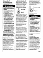
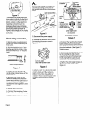
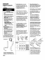
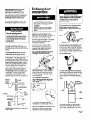
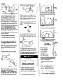
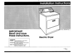
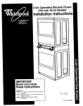
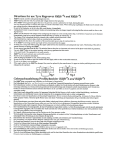
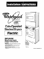
PRODUCTS
Coin-Operated
Stacked Dryers
Electric
/IMPORTANT:
IRead and save
1the-B instructions.
Important:
*Read these instructions before you start
to install the dryers.
*Save Installation Instructions for local
electrical inspectors use.
l Keep
Installation Instructions for future
reference.
windows and
raised handles
not available
on all models.
VI3
Part No. 3390148 Rev.ip
Before vou start
a
-
--~
-
. .a
Protection from weather: Pro1 )er
operation
requlres temperah 1res
above 45°F (7.2%).
The wiring diagram Is locate< I
inslde the control panel and
acces panels.
Check location where dryers will be
used. Proper installation ls your
responsibility.
The dryers must not be
installed or stored In an area where
they will be exposed to water and/or
weather. Make sure you have
everything
necessary for correct
installation.
Each of the dryers-b equipped
with a
timer, selector switches and lndlcator
lights. The timers are set to provlde 45
minutes (4 pins) of drying time when
activatti
by the coin slide. Timer
cams for 3&minute
(6 pins) and 60minute (3 pins) drying time are supplied
with the unit in the parts bag. See
Pages 9 and 10 for timer cam
changing
instructions.
The coin slide mechanisms,
control
panel lock and key, coin box, and
coin box locks and keys are not
included and are available
from
usual industry sources.
’ Back-draft
-
Power supply cords
not supplied with unit.
9
4
q
II
Ill I
Check utilities: Proper
supply connections
must be available.
>
\
.:
<
II
\
‘I
-‘\
.!a&
to support the total
/Iweight
of 315 pounds per unit.
.
! LI !vel floor: Maximum floor slope
dryers - 1 Inch.
.’
d:r
7
Tools needed
for installatiton:
Parts owner
must supply:
1 control panel lock and key
2 coin vaults and keys
E.S.D. vault mud hove
projecting
lock
2 coin slide m‘echanlsms
j2 power cords
(vertical
Parts may be ordered from
Greenwald
Industries. Inc. or
Equlpment Systems and
Devices, Inc.
l Greenwald
Phlltlps
xrewdrlver v
flat-blade!
screwdrh
er
Parts suppEed
for installat ion:
2 slide protectors
2 slide extensions
2 bolt and washer
assemblies
Page 2
h-4
-’
Location must be large
enough to fully open dryer doors.
See Page 9 for recessed area
requirements
and prduct
dimensions.
Fire Hazard
l
Do Not use or store gasoline,
paint, tb’nners and other
flammable
materials near
dryers.
l
Never install dryers up against
draperies or curtains or on
carpet.
l
Keep any and all Items from
falling or collecting
behlnd
the dryers.
l
Replace all access panels
before operating
dryers.
Failure to follow these instructions
could result in a fire or explosion.
dampers
Dryers may be
exhausted
from
bottom, rear, left or
right side. See ‘Exhaust
reauirements’,
Page 6.
Grounded
electrical
outlet Is
required.
See ‘Electrical
requirements’,
Page 3.
Personal Injury Hazard
More fhan one person Is
required to lift. tilt, or move the
dryers because of their weight
and size. Failure to follow these
instructions may result in
personal injury.
Important:
Observe all
governing
codes and
ordinances.
8 screw:
2,30-mil lute cams
2,60-mi lute corns
4, ?+I” good screws
Industti&
Inc.
1340 Metropolitan
Avenue
Brooklyn, NY 11237
telephone
(7 18) 821 -WOO or
toll free (800) 221-0982
fax no. (718) 417-7412
1 l Equipment Systems and
I
/ Devices, Inc.
1401 Dreshertown
Road
. P.O. Box 618
( Dresher PA 19025
I telephone
(215) 628-0860
fax no. (215) 643-4623
8)
Electrical
requirements.
OBSERVE AU GOVEdNlNG
AND ORDINANCES.
COdES
Electrical Shock Hazard
. Electrical ground Is required on this
appliance.
. If cold water pipe Is interrupted by
plastic, non-metallic
gaskets, or
other insulating materials, Do Not
use for grounding.
. Do Not ground to a gas pipe.
. Do Not modify the power supply
cord plugs. iflplugs will not fit the
outlets, have proper outlets installed
by a qualified
electrician.
. Use new 30-ampere power supply
cord kits. Do Not reuse old power
supply cords. Possible electrical
shock or fire could occur if old
power supply cords are used.
. Do Not have a fuse in the neutral or
grounding circuit. A fuse in the
neutral or grounding circuit could
result in an electrical
shock.
. Do Not use an extension cord with
this appliance.
. Check with a qualified electrician if
you are in doubt as to whether the
appliance
is properly grounded.
.1 Do Not plug the power supply cords
(pigtails) into a live wail receptacle
before connecting
the pigtails to the
dryer terminal blocks. Read ‘Direct
wiring connectton’.
Pages 4 and 5
for detailed instructions.
F:aiiure to follow these instructions
c:ouid result in serious injury or death.
I
” codes permit and a Separate
9’rounding wire Is used, it is recommlended that a eiectriclan
determine
thtat the grounding path Is adequate.
*. It Is-tie personal responsibility
and
ot 3llgatlon of the customer to
ccIntact-a qualified electrlclan
to
a: ;ylr& that the electrlcai
Installation
is adequate
and In conforjmance
w WI Natlonal ElectrIcal Code ANSI/
NIFPA 70-jlatest edltlon. and all local
cc2des and ordinances.
Allow sldck Iti
ttl le line between
the wall and the
aI Dpllance so that It can be moved if
SErrvlclng is ever necessary.
ihis appliance
must be connectec
to copper wlre only,
A 3/4’. U.L.-llsted strain relief must
be provided at each end of the
power supply cables (at the
appliance
and at the Junctionbox).
1. A three-wire. slngie 1Y-C+% 120/
240voit, &Hz, AC-on1 y, electrical
supply (or three-wire,
’ 20/208-volt
if
spedfled
on namepla tee>is
required on a separat 3.30-ampere
circuit, fused on both : Ides of the
line. (llme-deiay
fuse <f clrcult
breaker ls recommenc
ed.) The
wlrlng diagram is loca’ed
l&de the
control panel and act ess panels.
J-wire.
CConductor by a white cover. Cords
Skmuld be Type SRD or SRDT, with
3,/4’. U.L.-llsted strain reliefs and be at
le at 4 feet long. The four-wire power
sl apply cords and strain reliefs are not
P rovlded with the dryers.
4-wire. JO-amp
receptacle (14-JOB)
30-amp
recepL ~cie (IO-30R)
Figure 2
Figure 1
Typical Xl-ampere rece >tacle for use
where local codes pem It use of
flexible power supply cc rds (pIgtolls).
2. Local codes may pc ~rrnlt the USB of
U-L-Wed, 120/24&volt
mlnlmum. 3G
ampere dryer power SIapply cord kits
(plgtails). The cords coltaln
three.
No.-10 copper wires ar Id match
three-wire receptacles
of NEMA
Type 1G3OR, shown In I :gure 1.
Connectors
on the dry x end must
be ring terminals or spc Ide terminals
with upturned ends. U L.-listed.
3/4’ strain reliefs must t 8 provlded
at
the polnt the power su >ply cords
enter the appliance.
3. This appliance
can t 8 connected
dlrecity to the fuse disconnect
or
circuit breaker box thrcugh flexible
i armored or nonmetallic:
sheathed,
lOgauge
minimum, cc pper cable.
A 3/4’, U.L.-listed strain I elief must be
provlded
at each end Df the power
1supply cables (at the a Dpliance and
at the junction box).
’
4. For four-wire installat
appliance
wiring must
The appliance
cabinet
grounded
to the neutrc
must be connectec
grounding
wire (green:
supply cords.
on, the
x revised.
must not be
II terminal.
1 to me
of the power
i When four-wlre receptc icles of NEMA
i Type 14-30R are used, (see Figure 2)
1matching
120/240-volt
nlnlmum, 3&
ampere,
U.L.-listd dryc r power
supply cord kits (pigtall: #>must be
‘used. The cords contalr1 four, No.-10
copper conductors
wit I ring termlnals or spade terminals wlth
upturned ends on drye end
tetmlnating
In a NEW “.ype 14-30P
plug on supply end. The I fourth
(groundlng)
conductor
must be
: identified by a green OI green/
j yellow cover and the n, ?&al
LIternate electrical
:onnection
l
l
l
Eiectrlcal Shock Hazard
Electrical ground Is required on
.this appilance.
This appliance
must be
connected
to a grounded
metal. permanent
wiring system;
or an equlpment-grounding
conductor
must be run with
the circuit conductors
and
connected
to the equipmentgrounding
terminal or lead on
the appliance.
Disconnect
power supply cord
from the electric supply before
making these changes.
Failure
to do so may result in personal
injury.
Failure to do so may result in
electrical
shock or personal injury.
his appliance
ls manufactured
ie neutral terminal connected
Cle cabinet.
‘0 connect
younding
with
to
a separate
wire-
Jse grounding
wire and clamp
lssembiy (Part No. 685463) or No.-10
Jauge mlnimum, copper grounding
rrire. Connect grounding
wire to a
grounded
cold water pipe’ with the
clamp and then to the external
grounding
connector
on the dryers.
Do Not ground to a gas supply pipe
or hot water pipe. Do Not connect
me power supply cords to electric
power supply until the dryers are
permanently
grounded.
Do Not ground to &gas supply pipe
or hot water pipe, Do Not connect
the power supply cords to electric
power supply until the dryers are
permanently
grounded.
Page 3
A.
gw;(;)eundlw
(green
yellow
If local codes permlt c01 lnection of
cabinet-grounding
concjuctors
to
the neutral wires of the FBower supply
1cords:
,,
wlth
stripes)
1exte ,nal grounding
Figure 3
*Grounded
cold water pipe must
have metal continuity to electrical
ground and not be interrupted
by
plastic, rubber or other electrical
lnsulatin
connectors
such as
hoses, 8 i ngs. washer or gaskets
water meter or pump).
(includi
Any elec7% cat Insulating connector
should be Jumped as shown in
Figure 3 with a length of No.-4 wire
securely clamped
to bare metal at
bath ends.
1. Strip the outer covering back 3
Inches from the end exposing the
three wires.
copper
power supply cord
with strain relief
(30 amperes)
Figure 5
\ 1. Disconnect
Direct wiring connection_
center,
silvercolored
termlnal
block
screw
to fused
disconnect
box
or approved
wiring device tor
power supply cord
the power
supply.
2. Remove the terminal I >lock covers
by removing the screw s ?own in
Figure 5.
2. Strip the Insulation back 1 inch
from the end of each wire. Form
the bare wires into a V-shaped
hook.
Grounded
Neutral
Figure 7
4. Connect the neutral wire of each
power supply cord to the center,
silvercolored
termlnal of the terminal
block;. Connect the other wires to
the outer termlnals.
(See Flgure 7.)
Tighten screws.
5. Replace the termlnal block covers
by first installlng the tab of each
cover Into tie slot of the dryer rear
panel. (See Figure 5.) Secure the
covers with the mounting screws.
Rear panel
3/4’. VI.-llsted
strain relief (outside
di yer)
I Direct wiring connection
Figure 6
Figure 4
3. Loosen, do not remove,
center, silver-colored
terminal block.
the
xrew of the
4. Slide the end of the neutral
(white or center) wire under the
screw head with the open side of
the screw hook on the right.
Squeeze the wire together to form
a loop.
5. lighten
the screw firmly.
6. Connect the remalnlng 2 wires
to the outer screws the same way.
7. Tighten strain relief screws firmly.
Page 4
3. Attach a 3/4’, U.L.-listed straln relief
to each dryer through tt e power
supply cord holes. (See -igure 6.)
Tighten each strain relief firmly to
cabinet.
Place a power supply cord
or direct wire through ec ch strain
rellef.
6. Tighten the strain relief clamps
the power supply cords. (See
Figure 6.)
on
B
3. Attach a 3/4’, U.L.-listed strain relief
to each dryer through the power
supply cord holes. (See Flgure 6.)
Tlghten each strain relief firmly to
cabinet.
Place a power supply cord
or direct wlre through each strain
relief. Tlghten screws firmly.
If loc:l codes DO NOT permit
cablnetgroundlng
to the neutral
wires of the power supply cords:
metal cold water
1. Disconnect
the power
pipe
1
supply.
Bumps on
grounllng
clamp must
contact
pipe. I
2. Attach a 3/4’. U.L.-lIsted straln relief
to each dryer through the power
supply cord hales. (See Figure 6.)
Ighten each straln relief firmly to the
cabinet.
Place the power supply
cord or direct wire through each
strain relief. Tighten screws flrmly.
3. Remove
the grounding wires
(green wlth yellow stripes) from the
external groundlng
connectors
and
fasten under center, silver-colored
terminal block screws.
Connect separate copper groundlng
wlre
from external grounding
connector
to approved
ground.
l
*cB
\
GROUF :DlNG CLAMP
MUS BE TIGHT
C’N PIPE
/
Figure 9 \
Grounded. cold water plj )e must hove
metal continuity to electric 31ground and
not be interrupted by plast c. rubber or
other electrical Insulating connectors
such as hoses. fifflngs. wast ler or gaskets
(including water meter or Flump). Any
electrical Insulating tonne :tor should be
jumped as shown with a le igth of No.-4
wire securely clamped to t Iare metal at
both ends.
l
6. Replace
termlnal
blo zk covers.
Four-wire
cord
Ungrounded
neutral
conned
5. Connect the grounding
wire
(green with yellow stripes) of the
copper. 4-wire. power suppbf cord
or cable to the external grounding
connector.
Remt
with the other
grounding
wire.
)
7. Tighten straln relief ck mps on
power supply cords. (SE e Flgure 6.)
mower supply
4. Remove the grounding
wire
(green with yellow stripes) from each
external groundlng
connector
and
fasten under the center, sitvercolored. termlnal block screws.
llghten screws.
the neutral (white) wire
of each power supply card to the
center, silver-colored
terminal screws
of the terminal blocks. Connect the
other wires to the outer termlnals.
Tighten screws. (See Figure 10.) For
plain-end wires, see ‘Direct wiring
connection’.
Page 4.
&\Connect
ion
When fouriwlre, NEMA-t ape 14-30R
receptacles
are used, n latching
120/240-volt, 3Uamperc
, U.L.-listed
dryer power supply core I kits (pigtails)
must be used. The cord: contain
four, No.-1 0, copper COI lductors with
ring terminals or spade ‘ermlnals with
upturned ends on dryer end, terminating In a NEMA-type
4-3OP plug
on supply end.
Figure 8
the neutral wire of each
power supply cord to the center, silvercolor&d terminals of the terminal
blocks. Connect the other wires to the
outer termlnals. (See Fgure 8.) Tighten
screws. Forc6nnecting
plaln-end,field
wire, see ‘Direct wiring connectlon’,
Page 4.
7. Red&e
the terminal block
covers by first InstallIng the tab of
each cover Into the slot of the dryer
rear panel. (See Figure 5.)
Secure covers with the mounting
screws.
4. Connect
5. Connect separate, copper
groundlng wires (No. 10 minimum) to
a grounded,
metal cold water pipe’
by means of a clamp and then to
the cabinet of the appliance
at the
external groundlng
connectors.
Use
Part No. 685463 grounding wire and
clamp assemblies. Do Not ground to
a gas supply or hot water pipe. Do
Not connect
the power supply cords
to the electric power supply until
bath dryers are permanently
grounded.
(See Figure 9.)
8. Tlghten straln relief clamp
.
power supply cords.
4-wire
ungroundcmd
neutral
on
.
Figure 1[1
1. Disconnect
the powder
supply.
i
2. Remove the terminal block covers
by removing the screw shown in
Figure 5.
Page 5
Exhaust
reqdrements
Exhaust materials
supplied.
are not
Fire Hazard
l
Do Not use non-metal,
flexible
duct.
l
Do Not use metal duct smaller
than four Inches in diameter.
l
Do Not use exhaust hoods with
magnetic
latches. Improper air
supply for exhaustlng
may
result in a fire.
l
Check that exhaust system is
not longer ttian specified.
Exhaust systems longer than
specified will:
- Accumulate
Ilnt.
- Shorten the life of the product.
- Reduce performance,
resulting In longer drying
times and Increased energy
usage.
Failure to follow spectfications-,
may result In a fire.
l
Dryers must be exhausted
to
the outside.
l
Do Not exhaust dryers into
chimney, furnace cold air duct,
attlc or crawl space, or any
other duct used for venting.
l
Clean the exhaust system
frequently.
l
Do Not Install flexible duct
under wall, ceiling or floor
materials.
Accumulated
lint could result in
fire or cause moisture damage.
Use duct tape to
seal all joints.
Metal flexible duct mus be fully
extended
and supports d when
the dryers are In final pc sit-ion. DO
NOT KINK OR CRUSH TH1’ DUCT. The
metal flexlble duct mus be
completely
opeti to allc IW
adequate
exhaust air tc Bflow.
Allow as much room as possible
when using elbows or rr aking turns.
Bend duct gradually to avold
kinklng. Remove 8x1~s:; flexible duct
to bvold sagging and ki nklng that
may cause reduced alr low.
The exhaust duck can t = routed up.
down, left, right or strais ht out the
back of the dryers. The lower dryer
can also be exhausted
hrough the
bottom of the dryer. PrcIduct
dimensions and recesse 3 area
requirements
are glven Dn Page 9.
For exhaust systems not covered
by the exhaust length cl )art. see
WhIrlwool Service Manuc &
‘Exhausting
WhIrlpool Dryers’, Part
No. 603197, available
fit m your
Whlrlpool parts diitributc r.
Rear Exhaust: The maxim urn length
of the exhaust system dc !pends on
the type of duct, the nul nber of
elbows, and the type of exhaust
hood. The maximum ler gth for both
rigld and flexlble duct is : hewn in
the chart.
lumber of
0” turns
Exhaust Hood T rpe
better
Four-inch metal exhaust duct is
required.
Plan installation- to use
the fewest number of elbows and
turns.
Page 6
An exhaust hood should cap the
exhaust duct to prevent exhausted
air from returnlng into the dryers.
The outlet hood must be at least 12
inches from the ground or any
object that may be In the path of
the exhaust.
A main exhaust duct can be used
for exhausting a group of dryers.
Main exhaust duct should be sized
to remove 200 CFM of alr per
dryer. Large-capacity
lint screens
of proper design may be used In
the main exhaust duct if checked
and cleaned frequently.
The room
where the dryers are located
.
should have make-up air equal to
or greater than the CFM of all the
dryers in the room.
air flow
1main collector dud
A
30 Ft.
24 Ft.
16 Ft.
exhaust oifflow
If the dryers are installed in a
confined area, they must be
exhausted
to the outside and
provislon must be made for
enough air for combustion
and
ventilation.
Check governlng
codes and ordinances.
Also refer.
to the ‘Recessed area and closet
installation instructions.’ Page 9.
A’
43 Ft.
33 Ft.
23 Ft.
good
Service check: The back pressure In
any exhaust system used must not
exceed 0.6 Inches of water column
measured with an inclined
manometer
at the point that the
exhaust system connects
to the
dryers.
Aps@%!
A’
exhaust airflow
Side or Bottom Exhaust: The
maxlmum length of the exhaust
system If dryer is exhausted
out the
side or bottom is 16 feet with two
external elbows and hood.
Maxlmum
length of 4
dia. rigid
metal duel
Maximum
length of 4
dia. flexibl
metal due
Back-drafl
damper kits (Part No.
3391910) are avallable
from your
Whirlpool dealer and should be
installed in each dryer’s exhaust
duct to prevent exhausted
air
from returning into. the dryers and
tb keep the exhaust in balance
within the Fain exhaust duct.
Unobstructed
air openlngs are
required.
Exhaust duct
connectSor:
Each exhaust duct should enter
the maln duct at an angle
pointing In the dlrectlon of the
airflow. Ducts enterlng from the
opposlte side should be staggered
to reduce the exhausted
air from
lnterferlng with the other ducts.
The maxlmum angle of each duct
entering the main duct should be
nc more than 30”.
Prod?! Damage
Keep air openings free of
dry-cleaning
fluid fumes. Fumes
create acids whtch,when
drawn
through the dryer heating units,
can damage dryers and loads
being dried.
A clean-out cover should be
located on the main exhaust duct
for periodically
cleaning
the exhaust
system.
An exhaust hood should cap the
outside end of the maln duct to
prevent exhausted
air from returning
to the dryers. If an exhaust hood
cannot be used, the outslde end of
the main duct should have a sweep
elbow dlrected downward.
If the
maln duct travels vertlcaliy
through
the roof, rather than through the
wall, Install 180” sweep elbow on the
end of duct at least 2 feet above
the hlghest part of the building,
The opening wall or rcof shall have
a dlameter
l/2 Inch larger than
the exhaust duct diameter.
The
exhaust duct should be centered
in
the opening.
exhaust
hood or
;wall
If&
1main exhaust duct
Electrical
Shock t lazard
Disconnect
both power supply
cords before maklng these
changes.
Failure to do so may I esult In
electrical
shock or personal
injury.
2. Remove the duct tape from the
Internal exhaust duct and the
straight duct. Repeat for the other
dryer.
I
Determine
which
directi In you
the eti rust ducts to
the dryers. Both dryers can be
exhausted
straight out tt be back or
from the rlght or left slde The lower
dryer can also be exhausted
through the bottom.
need to attach
3. Remove
Next, determine
the leq iih of
exhaust duct you will ne ?d to
connect
the dryers to exhaust
hoods or the maln exhal st.
To connect
exhau St duct
straight out the ba zk-
exhaust duct
Atta
each dryer duct. Then connect
exhaust ducts to exhaust hcods
or maln exhaust.
Use due:! tape
to seal all Joints.
To connect
exhau?
duflc;lttlh~ugh the qht
-
I\
I
&zJ
or
the screw from the duct
clip that attaches
the straight duct
to the back of the cabinet.
Depress
the clip and remove the straight
duct using a twisting motlon through
the rear exhaust openlng.
Repeat
for the other dryer.
4. Reach through the rear exhaust
openlng and depress center of tabs
on the plastic opening cover cn the
side you want to exhaust through.
Remove the cover. Repeat for other
dryer.
;“.y4
-\
\
\
.\
180”
2 ft. min.
\
\
‘.
sweep
elbow
j vertical duct ~
%
‘highest point
i main collector
duct
-L-- -------m=Ql -
‘of building
‘.
\
R
roof
Do Not install screening
end of duct.
or cap
over
1. Remove access panel by
releasing two locking clip! with a
small, flat-blade
screwdrib er. The
clips are located
four inct es in from
each side of the access panel.
Repeat for other access canel.
5. Attach a three or four-section
elbow to the straight duct using
duct tape. Repeat with the other
elbow and straight duct.
Page 7
Internal \
exhaust duct
3.1 Remove duct tape from In .ernal
exhaust duct and the straight duct.
dryel
rear
Y
6. [Insert elbow end of duct pieces
through the side opening.
Reach
through the access panel openlng
and attach
elbow to the Internal
exhaust duct. Check the length of
stralght duct extending
out the
side of the cabinet.
If duct extends
too far to make the exhaust duct
connection,
mark a line around the
stralght duct one Inch out from the
cabinet.
Remove the duct and elbow
and cut the straight pipe to the
length needed.
Reinsert the duct
pieces. Use duct tape to connect
the elbow to the internal exhaust due
Repeat for the other dryer.
>7. llnsert the plasttc
exha-ust opening.
cover
8. jRe place
the access
9. \Use duct
tape
to seal all joints.
10. :Push the four inch, stralght duct
through the rear exhaust opening
and onto the Internal duct as far
as it will go.
4.j Remove the screw from the I duct
clip tit
attaches the straight duct to
the back of the cabinet.
Dep Bss the
clip and remove the straight c uct
using a twisting motion througl i the
rear exhaust openlng.
I..\ Check that the legs extend one
inch from the bottom of the dryer.
5.1 Measure from the large en( 1 of the
straight duct and mark at four
inches. Cut the stralght duct to that
I
7 1. j Insert me elbow through the
rear exhaust opening.
Ins& elbow
into the bottom exhaust openina.
+ tront
of dryer
6.j Reach through the rear ezd xlust
opening and depress center c tf tabs
on one of the side, plcxtic opt ning
covers.. Remove the cover.
12.‘Slide the straight du
elbow approximatety
one inch.
Use duct tape to seal both joints.
. sc,ew h&d x(fastens against
edge of cabinet)
7.1 With a Phillips
through the rear
and remove the
me cover to the
Carefully remove
through
the rear
iili~rt
the
bottom exhaust
-cover through
the side exhaust
opening.
Put me
cover over me
rear exhaust
opening with the
tab pointing down
to bottom of dryer.
Insert screw through the hoie In the
cover that Is on the &tslde of the
cabinet.
Ttghten screw.
screwdriver,
reach
exhaust oper ling
screw that al taches
dryer base.
the cover ar d screw
exhaust oper ring.
floor Damage
Slide dryers onto cardbaal
hardboard
before moving
across tloor.
Failure to do so mq.causc!
damage
to floor covering.
d or
the lower dryer access
panel by releasing the two locking
clips with a small, flat-blade
screwdrtter.
The clips are located
four inches in from each side of-the
access panel.
Uft access panel
off the bottom clips and set aside.
14jReptace
cover.
1
I
Page 8
.
ol!
*front
d dryer
duct
of the
Note: You must use a threesection
elbow to connect
exhaust duct
through the bottom of the tower
dryer.
2. i Remove
:
I I--
Into the rea
panels.
To connect
exhaust
through the bottom
lower dryer only -
::
4Aont
of dryer
8.\, Move dryers into operatinc
pdsltion. Reach through the 2 access
opening and mark the exhau: t
opening location on the floor. Move
dryers out of the operating
pc sition.
9.: Cut opening
through
the fl oar.
the side exhaust
15. (Move the dryers into operating
position. Check that the elbow Is
through the bottom exhaust
opening.
Replace the access
panel.
763onnect
the elbqy toe-must
d&t. Then connect
exhaust duct
to exhaust hood or maln exhaust.
Use duct tape to seal all Joints.
Recessed area
and closet
installations
Cochange to a
30, or 60-minute
:iming cam
Closet vieqnr
Side view
,<
/
I 0’-I,
0’
/Additional
clearances
for
wall. door and
) floar moldings
may be
required.
ddiial
XC0
inlay
be
eded for
xhausl elbow.
Fire Hazard
Dryers MUST be exhausted
to
outslde.
Failure to do so may result in a fire.
l
Do Not exhaust dryers into a
chimney, furnace cold air duct,
attic or crawl space, or any other
duct used for venting.
Accumulated
lint could result In a
fire or cause moisture damage.
Electrical
l
This appliance
may be installed
a recessed area.
I,
Disconnxt
both power supply
cords from the electric power
supply before making these
changes.
Change timing cams
before completing
electrical
connection.
Failure to follow these instructions
may result in electrical
shock or
~personal injury.
I
closet
door
in
Unobstructed
air openings are
required for laundry equipment
when door Is Installed. Door must
have two centered
openings as
Illustrated.
Both openings must
provlde a minimum of 72 square
Inches of unobstructed
airflow
as shown.
I
~
-Each dryer Is equipped
with a 45
minute timer cam that provldes 45
mlnutes of drying time when
activated
by the coin slide.
You can Install the 3Gmlnute or 60minute timing cam (shipped with
each dryer) as follows:
The installation spacing is in the
minimum allowable.
Additional
spacing should be considered
for
ease of Installation, servicing, and
compliance
with local codes and
ordinances.
Do Not block air bow at the bottom
front of the dryers with laundry or
rugs. Airpow from the bottom of
dryer Is needed for operating
efficiency.
Shock Hazard
Companion
appllatice
should be considered.
1Product
y lacing
1. Unlock control panel. Lift up and
rotate out from cabinet. Control
panel will still be attached
to
cabinet.
dimensions
2. Reach into control panel area.
Use a Phillips screwdriver
to loosen
(but not remove> timer mounting
bracket screw. Lift up to remove
timer assemble and bracket from
cabinet.
Side View
1
I
door +
door
l/4’
/ ratchet tooth
rO’
L
-
t
-0pprox.
1’
Additional
clearances
for
wall, door and
floor moldings
,moyb
required or
If external
, exhaust elbow
is u
3. Turn the timing cam by hand until
the ‘V--shaped
notch lines up
below the ratchet tooth.
Recessed
front view
Page c
Now start.. .
With dryers in laurldry
I
Il.
area.
Check that each leg is
approximately
1 inch frc)rn base.
‘2.
Wipe the Interior of the drums
thoroughly with a damt ) cloth.
4. insert a narrow, flat-blade
screwdriver
under the timing cam
near the clock shaft. Gently lift
cam straight up and off shaft
making sure that the ‘V-shaped
notch clears the ratchet tooth.
:3
.
Install coin vaults and Ic cks (not
supplled) into meter cc se openings.
14
5. Place new cam (hub side down)
over clock shaft. tine up flat side
of shaft with flat side of cam hole.
Check that drive lug is in place.
= .
Install control panel
(not supplied).
lot < and key
6.
Open control panel and rest It on
the bottom edge of the opening.
Attach slide extension (with flange
pointing down) to one of the coinslide mechanisms.
Insert the colnslide mechanism
through the
opening to left of the control panel.
!
6. Turn cam until Y/‘-shaped
lines up with ratchet tooth.
notch
L
7. Press cam down in place on
motor shaft. Make sure that ‘V’shaped notch clears the ratchet
tooth.
8. Reattach
assembly;
the timer bracket
then tighten the screws.
9. Repeat
steps for other timer.
I
I
Shock I iazard
-a--Electrical
~~
‘Control p&e1 m&t b4 I closed
and locked at all time s.
1
Failure to do so could result in
serious injury or death .
. .-- ,.
Secure coin slide mechanism
from itide the control panel
using the 3/l 6’ bolt and wast
included with the slide
mechanism.
Install coin box.
10. Close and lock the control
panel.
8.
Repeat Steps 6;and 7 for the other
coin slide mechanism.
Close control
pan
If you wish to change tt e 45minute
dryer timing cams to eit >er 3@ or 60minute timlng cams, set I ‘To change
to a 3C- or 6Uminute tin ling cam,’
Page 9. Complete
all 01 the steps
given In that section be’ore going to
Step 6.
Electrical Shock I iazard
Dlsconnect
electrka
I power at
the service panel (fu ;e box or
clrcult box).
Fallure lo do so coulc I result In
serious Injury or deat 1.
Page 10
911
r.
Insert top of wire guard Into holes
on each side of the coin slide
mechanism.
Insert screws through
hooked ends of guard and tighten.
Repeat for other wtre guard.
ilO.
ib I
: Make electrical connection.
See
/ ‘Electrical requirements,’
Page 3.
Turn on electrIcal
Move dryers to their
permanent
location.
supply.
The installation
of
your electric dryers
now complete.
‘11.
Check levelness of dryers by
placing a carpenter’s
level on top
of the dryers or collar, first side to
side, then front to back. If dryer is
not level, adjust the front legs up or
down. Make the final check with
the level.
power
15
is
n
Check to make sure you have ? all
your tools.
I
1
To exhaust the dn/ers, see ‘Exhaust
requlremenk’
and ‘Exhaust duct
( connection’,
Pages 6.7 and 8.
Personal Injury Hazard
~ To prevent tlpping. tether
bracket must be secured to wall
studs or concrete wall.
Failure to do so could
personal Injury.
result in
: Tether bracket,
located at rear
of the top dryer.
I
1
1 Attach both ends 6f tether
! located at the rear of the top
/ dryer to a secured 2x4.
14 .
) Check to see that all parts you
removed from the Installation
parts packages
are now installed
I in the dryers. If you have an extra
part, go back though
the steps to
see what you skipped.
Numbers
correspond
with steps.
Page 11
Moving the:
dryers to a new
locatton.. .
If dryers
do not operate
properly.. .
I
Check the following
sure thcrt:
1, Electric supply
l
to be
l
Is.connected.
2. Circuit breakers
fuses blown.
are not tripped
or
3. Doors are closed.
4. Controls are set in a running
‘ON’ position.
or
\me whirlpod
Consumer Assistance
i Center will answer any questions
1about operating
or maintainlng
your
idryers not covered
in your Operating
i Instructions. The Whlrlpod Consumer
/Assistance Center number Is (800)
~25%1301. Dial just as you normally
:dial long distance - the call is free.
l
bnut off electric
supply t 3 dryers.
Disconnect
power supp y cords
and external grounding
wires.
Tati securely to dryer.
Tape the drums to the fr xt
panel.
l
Tape doors.
l
Adjust leveling
legs all tt e way in.
Before Installing dryers In c I )xw
location, check with a Ilcc !nsed
electrlcian
to confirm tha the
supply voltage matches ti >e
voltage specified on the : erial/
rating plate located In the! door
well of the dryers.
C’ XFORATON
Part No. 3390148 Rev./D
@ 1993 Whhpool Corporation
Prepared
by Whirlpool
Corporation,
Berrton Harbor,
,Printed on recycled paper.
10% post cansumer waste/
ELI% recovered materlals.
Michigan
49022
Printed in U.S.A.