1
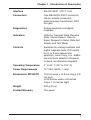
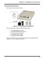
Model MT202TD
1200 BPS Leased Line Modem
User Guide
User Guide
MT202TD
P/N 82096502 Revision C
COPYRIGHT
This publication may not be reproduced, in whole or in part, without
prior expressed written permission from Multi-Tech Systems, Inc. All
rights reserved.
Copyright© 2000-2003, by Multi-Tech Systems, Inc.
Multi-Tech Systems, Inc. makes no representations or warranties with
respect to the contents hereof and specifically disclaims any implied
warranties of merchantability or fitness for any particular purpose.
Furthermore, Multi-Tech Systems, Inc. reserves the right to revise this
publication and to make changes from time to time in the content
hereof without obligation of Multi-Tech Systems, Inc. to notify any
person or organization of such revisions or changes.
Revision
B
Date
3/30/01
Description
DIP Switch settings updated. Moved
connections into separate section.
C
PATENTS
1/04/03
Change MT202TD graphic
This device is covered by one or more of the following patents:
6,031,867; 6,012,113; 6,009,082; 5,905,794; 5,864,560; 5,815,567;
5,815,503; 5,812,534; 5,809,068; 5,790,532; 5,764,628; 5,764,627;
5,754,589; D394,250; 5,724,356; 5,673,268; 5,673,257; 5,644,594;
5,628,030; 5,619,508; 5,617,423; 5,600,649; 5,592,586; 5,577,041;
5,574,725; D374,222; 5,559,793; 5,546,448; 5,546,395; 5,535,204;
5,500,859; 5,471,470; 5,463,616; 5,453,986; 5,452,289; 5,450,425;
D361,764; D355,658; D355,653; D353,598; D353,144; 5,355,365;
5,309,562; 5,301,274. Other Patents Pending
TRADEMARKS
Multi-Tech and the Multi-Tech logo are trademarks of Multi-Tech
Systems, Inc.
Multi-Tech Systems, Inc.
2205 Woodale Drive
Mounds View, Minnesota 55112
(763) 785-3500 or (800) 328-9717
Fax (763) 785-9874
Technical Support (800) 972-2439
Internet Address: http://www.multitech.com
Contents
Chapter 1 - Introduction and Description ......................... 5
Introduction ........................................................................... 5
Description ............................................................................5
Technical Specifications ........................................................ 6
Chapter 2 - Installation and Connection ........................... 8
Introduction ........................................................................... 8
Power ....................................................................................8
Safety Warnings .................................................................... 8
Unpacking the Modem .......................................................... 9
Modem LED Indicators ........................................................ 10
Controls on PC Board ......................................................... 11
Computer or Terminal Connections ..................................... 12
MT202TD RS-232 Signal Descriptions ...............................13
Modem and Phone Line Connection ...................................14
DIP Switch Settings ............................................................. 15
DIP Switch and Switch Settings & Functions ......................16
Leased Line Connections ....................................................17
Chapter 3 - Modem Testing ..............................................18
Introduction ......................................................................... 18
Local Analog Loopback Test ...............................................18
Digital Loopback Test ..........................................................19
Chapter 4 - Warranty, Service,
and Technical Support ................................................20
Limited Warranty .................................................................20
Online Warranty Registration ..............................................20
Service ................................................................................ 21
Technical Support ................................................................22
Internet Sites .......................................................................22
Recording Modem Information ............................................ 22
Appendix - Regulatory Compliance.................................23
FCC Part 15 – Class A Statement .......................................23
FCC Part 68 Telecom ..........................................................24
Index ...................................................................................26
Chapter 1 - Introduction & Description
Chapter 1 - Introduction and Description
Introduction
This manual provides instruction for installing, cabling,
operating, and troubleshooting Multi-Tech System’s model
MT202TD 1200 bps modem.
Description
The MT202TD is a low speed asynchronous modem which
employs Frequency Shift Keyed (FSK) modulation and works
in full duplex over four-wire or in half-duplex over two-wire
leased line networks.
The MT202TD is compatible with all Western Electric series
202 leased line data sets, except those with reverse channel.
The MT202TD is compatible with Western Electric 202 and
202T data sets as well as older 202-C, 202-D, 202-E, and
202-R models.
5
MT202TD User Guide
Technical Specifications
Your MT202TD modem meets the specifications listed below:
6
Model Number
MT202TD
Data Rate
0–1200 bps
Compatibility
Western Electric 202 and 202T
Data Sets, 202C, 202D, 202E,
202R models
Mode of Operation
2-wire half duplex or 4-wire full
duplex
Line Requirements
2- or 4-wire leased line
unconditioned
Modulation
Frequency Shift Keyed (FSK)
Carrier Frequencies
Mark:1200Hz; Space: 2200Hz;
Soft Carrier: 900Hz
Transmit Level
-0 dBm Adjustable to -9 dBm via
Dip switch
Frequency Stability
±0.01% (crystal controlled)
Receiver Sensitivity
-40 dBm under worst case
conditions
Timing
Request to Send/ Clear to Send:
180 ms
Carrier Detect:
Turn on 30 ms
Turn off 10 ms
Receiver Squelch:
Default 156 ms
Soft Carrier:
Default 25 ms
Minimum 10 ms
Chapter 1 - Introduction & Description
Interface
EIA RS-232C / ITU-T V.24
Connectors
One DB-25 RS-232 C connector
(25-pin female connector),
external power transformer, RJ11
line jack
Diagnostics
Analog loopback and digital
loopback
Indicators
LEDs for Transmit Data, Receive
Data, Carrier Detect, Clear to
Send, Request to Send, Data Set
Ready, and Test Mode
Controls
Switches for analog loopback and
digital loopback tests, DIP switch
for 2- or 4-wire leased line
selection, Local Copy, 0 or -9dBm
transmit level selection, Request
to Send, and Receiver Squelch
Operating Temperature
0° to 50° C (32° to 120° F)
Power Requirements
117 VAC, 60Hz, .1 amp
Dimensions MT202TD
10.8 cm wide x 14.8 cm long x 2.9
cm high
(4.25 inches wide x 5.8 inches
long x 1.15 inches high)
Weight
224 g (8 oz.)
Limited Warranty
Two years
7
MT202TD User Guide
Chapter 2 - Installation and Connection
Introduction
The installation of the MT202TD consists of setting DIP
switches to the appropriate settings and then making the serial,
phone line, and electrical power connections.
Power
Power is supplied to model MT202TD through an AC power
transformer. The transformer supplies low voltage DC to the
modem and plugs into any conventional 117 VAC, 60 Hz,
power outlet.
Warning: Use only the power transformer supplied with the
modem. Use of any other transformer could cause damage to
the modem.
Safety Warnings
l
l
l
l
l
l
8
Never install telephone wiring during a lighting storm.
Never install telephone jacks in wet locations unless the
jack is specifically designed for wet locations.
This product is to be used with UL- and CUL-listed
computers.
Never touch uninsulated telephone wires or terminals
unless the telephone line has been disconnected at the
network interface.
Use caution when installing or modifying telephone lines.
Avoid using a telephone (other than a cordless type) during
an electrical storm. There is a remote risk of electrical
shock from lightning.
l
Do not use the telephone to report a gas leak in the vicinity
of the leak.
l
To reduce the risk of fire, use only 26 AWG or larger
telecommunication line cord.
Chapter 2 - Installation & Connection
Unpacking the Modem
Remove all items from the box.
Figure 2-1. Unpacking the MT202TD
The packing box contains the following items:
l
l
l
l
l
One MT202TD modem
One MT202TD User Guide
One power transformer
One RJ11/RJ11 cable
One RJ11/RJ48 cable
If any of these items are missing, please contact Multi-Tech
Systems or your dealer/distributor.
9
MT202TD User Guide
Modem LED Indicators
Figure 2-2. LED Display
The MT202TD has seven diagnostic LED indicators. They are:
10
TD
Transmit Data - This LED blinks when data is being
transmitted: on for a space; off for a mark. The state of
this LED matches the TD circuit on Pin 2 of the RS232C/V.24 interface.
RD
Receive Data - This LED blinks when data is being
received: on for a space; off for a mark. The state of this
LED matches that of the RD circuit on Pin 3 of the RS232C/V.24 interface.
CD
Carrier Detect - This LED lights when a valid carrier
tone has been detected.
CTS
Clear to Send - This LED lights when the modem
responds to a Request to Send signal after a fixed
delay. The terminal equipment may start transmitting
data after this signal is on (high).
RTS
Request to Send - This LED lights when the Request
to Send signal from the DTE is on.
DSR
Data Set Ready - This LED lights when the modem is
powered on.
TM
Test Mode - This LED lights when the modem is in Test
Mode.
Chapter 2 - Installation & Connection
Controls on PC Board
The MT202TD circuitry is on a single printed circuit (PC) board.
This board contains one 8-position DIP switch (numbered 1-8),
an analog loopback test switch, and a digital loopback test
switch. The factory default setting is for 4-wire, full-duplex
operation in normal mode. If you are using the modem in a 2wire configuration or using one of the test modes, you must
change the switch positions. Refer to page 19 for switch
setting and function information.
Digital Loopback
Switch (DLB)
Analog Loopback
Switch (ALB)
DIP-Switches
(1-8)
LED Indicators
1
2
3
4
5
6
7
8
Default Switch
Positions
Figure 2–3. PC Board Controls
11
MT202TD User Guide
Computer or Terminal Connections
Your computer or terminal is connected to the MT202TD via the
modem’s EIA RS-232C / ITU-T V.24 interface connector. This
connector is a standard interface, with a 25-socket female
connection. Therefore, your computer or terminal requires a
standard RS-232C / V.24 cable with a male connector on the
modem end, and a male or female connector at the computer
or terminal end, depending upon the computer or terminal
connector.
Plug the RS-232C / V.24 cable into the RS-232C / V.24 connector on the modem. If screws were provided with your cable,
insert and tighten the screws to secure the connection.
Although the RS-232C / V.24 interface connector is designed
for 25 signal paths, only eight of these signals are used by the
MT202TD.
If your computer or terminal did not come with an RS-232C /
V.24 cable, you may purchase a standard “straight-through”
RS-232C / V.24 cable from your local computer retailer.
12
Chapter 2 - Installation & Connection
MT202TD RS-232 Signal Descriptions
Pin MTS Circuits
Name EIA ITU-T
Function
Signal
Source
2
SD
BA
103
Transmitted Data
DTE
3
RD
BB
104
Received Data
DCE
4
RTS CA
105
Request to Send
DTE
5
CTS CB
106
Clear to SendDCE
6
DSR CC
107
Data Set Ready
DCE
7
SG
AB
102
Signal Ground
-----
8
CD
CF
109
Data Carrier
Detector
DCE
9
+V
+V
-----
Test Voltage
DCE
DTE= Data Terminal Equipment (terminal or computer)
DCE= Data Communications Equipment (the modem)
13
MT202TD User Guide
Modem and Phone Line Connection
This section describes how to install and connect the
MT202TD.
Installation Steps:
1. Verify that the remote modem is set for Bell 202- or 202Tcompatibility.
2. Connect the modem to the leased line jack using one of the
two RJ11 cables provided with the modem.
3. Remove the case (see the next page). Verify leased-line
transmit level (DIP switch #5) setting is at either 0 dBm
(down) or -9 dBm (up). Refer to the following page for more
information on DIP switch settings.
4. Attach the MT202TD to your PC or terminal with an RS232 (or V.24) cable.
5. Connect the power transformer to the modem and an AC
outlet.
PWR
RS232
LINE
To DTE
Figure 2-4. Back Panel Connectors
14
Chapter 2 - Installation & Connection
DIP Switch Settings
DIP switches are located on the MT202TD circuit board as
shown in Figure 2-3. For information about DIP switch settings
and functions, refer to the chart on page 19.
To access the switches, remove the modem’s cover.
To remove the cover:
1.
2.
3.
4.
5.
6.
7.
Unplug the power transformer from the wall socket.
Unplug the phone line.
Turn the modem upside down.
Remove the two screws.
Place the modem right side up.
Remove the cover to expose the DIP switches.
After completing the necessary DIP switch
changes, replace the modem cover and screws
before re-connecting the phone and power lines.
Remove Screws
Figure 2-5. Removing Screws
15
MT202TD User Guide
DIP Switch and Switch Settings & Functions
(See Figure 2–3.)
Switch
Function
Position
1
Local Copy Enable
Local Copy Suppress
UP*
DOWN
2
Two-Wire Lease Line
Four-Wire Lease Line
DOWN
UP*
3
Two-Wire Lease Line
Four-Wire Lease Line
DOWN
UP*
4
Two-Wire Lease Line
Four-Wire Lease Line
UP
DOWN*
5
Transmit 0 dBm
Transmit -9 dBm
DOWN*
UP
6
Request to Send Forced On
Request to Send Controlled by DTE
on Pin 4
DOWN*
UP
7
Receiver Squelch Enable
Receiver Squelch Disable
DOWN*
UP
NOTE: UP equals OPEN
DOWN equals CLOSED
*********************************************
ALB
Analog Loopback Test Mode
Normal Mode
ALB
Normal*
DLB
Digital Loopback Test Mode
Normal Mode
DLB
Normal*
* Indicates default position
16
Chapter 2 - Installation & Connection
Leased Line Connections
The MT202TD modem operates on leased lines and may
be configured in two ways: two-wire or four-wire. In a
leased-line application, the line is continuously connected
to the modem. In two-wire leased-line applications, only
one modem may transmit at a time (this is known as halfduplex). In a four-wire configuration, one pair of wires
should connect to the transmitter of the local modem and
the receiver of the remote modem. The other pair of wires
should connect to the remote modem’s transmitter.
UUUUU
UUUUU
Digital
Computer or Terminal
Analog
Analog
Local Modem
Digital
Remote Modem
Computer or Terminal
Figure 3-1. Four-Wire Leased Line Connection
In multi-point leased line configurations, the user must
arrange to have the phone company install the multi-point
network using a four-wire configuration. The following
illustration shows a typical bridged multi-point configuration.
MT202T
MT202T
MT202T
MT202T
B
B
B
Boxes marked
“B” are Bridge
Circuits
MT202T
MT202T
MT202T
600 ohms 600 ohms
Figure 3-2. Four-Wire Multi-Point Connection
17
MT202TD User Guide
Chapter 3 - Modem Testing
Introduction
The MT202TD has two diagnostic tests: Local analog loopback
and digital loopback.
A loopback test involves entering data from your PC and
looping that data through the circuits of your modem and/or a
remote modem. When the loop has been completed, the data
received on the monitor should match the data entered on the
keyboard.
The local analog loopback test allows you to verify that the
modem’s transmit and receive circuits are functioning properly.
Refer to the Local Analog Loopback section on the following
page for more details.
The digital loopback test allows you to verify that the local
computer or terminal, the two modems, and the transmission
line between the devices are functioning properly. See the
Digital Loopback Test section in this chapter for more
information.
Local Analog Loopback Test
The analog loopback test is performed by placing the analog
loopback (ALB) switch in the ALB position (see Figure 2-3 in
Chapter 2 of this user guide). When the switch is set to the ALB
position, the CD, CTS, RTS, DSR, and TM indicators should
light.
In this test, data from your computer or terminal is sent to your
modem’s transmitter, converted into analog form, looped back
to the receiver, converted into digital form, and then received
back at your monitor for verification. No connection to the
phone line is required. The TD and RD indicators blink as keys
are pressed. If your modem is configured for two-wire operation, the Local Copy DIP switch must be enabled (see Chapter
18
Chapter 3 - Modem Testing
2 for DIP switch setting information).
CONNECT
UUUUUUUU
UUUU
Digital Analog
Computer or Terminal
Local MultiModem
Figure 3-3. Local Analog Loopback Test
Digital Loopback Test
The digital loopback test is an on-line test that loops data sent
from one modem across the phone line to another modem, and
then back to the first modem. This test checks the phone line
and modem integrity.
This digital loopback test is used on modems configured for
four-wire leased lines. To perform this test, the DLB switch on
the modem’s circuit board must be set to the DLB position (see
Figure 2-3 in Chapter 2).
In this test the local modem is placed in digital loopback mode.
Data is entered and transmitted from the remote modem (which
is not in digital loopback mode), sent across the phone line to
the local modem, and looped back to the remote modem.
OK
UUUUUUUUU
UUUUU
Digital Analog
Computer or Terminal
Local MultiModem
Analog Digital
Remote MultiModem
Computer or Terminal
Figure 3-4. Digital Loopback Test
19
MT202TD User Guide
Chapter 4 - Warranty, Service,
and Technical Support
Limited Warranty
Multi-Tech Systems, Inc., (hereafter MTS) warrants that this
product will be free from defects in material or workmanship for
a period of two years from date of purchase, or if proof of
purchase is not provided, two years from date of shipment.
MTS MAKES NO OTHER WARRANTY, EXPRESS OR
IMPLIED, AND ALL IMPLIED WARRANTIES OF MERCHANTABILITY AND FITNESS FOR A PARTICULAR PURPOSE ARE
HEREBY DISCLAIMED.
This warranty does not apply to any products which have been
damaged by lightning storms, water, or power surges or which
have been neglected, altered, abused, used for a purpose
other than the one for which they were manufactured, repaired
by Customer or any party without MTS’s written authorization,
or used in any manner inconsistent with MTS’s instructions.
MTS’s entire obligation under this warranty shall be limited (at
MTS’s option) to repair or replacement of any products which
prove to be defective within the warranty period or, at MTS’s
option, issuance of a refund of the purchase price. Defective
products must be returned by Customer to MTS’s factory —
transportation prepaid.
MTS WILL NOT BE LIABLE FOR CONSEQUENTIAL
DAMAGES, AND UNDER NO CIRCUMSTANCES WILL ITS
LIABILITY EXCEED THE PRICE FOR DEFECTIVE
PRODUCTS.
Online Warranty Registration
To register your modem online, go to:
http://www.multitech.com/register
20
Chapter 4 - Warranty, Service & Technical Support
Service
In the event that service is required, products may be shipped,
freight prepaid, to our Mounds View, Minnesota, factory.
Please send modems that require repairs to the following
address:
Multi-Tech Systems, Inc.
2205 Woodale Drive
Mounds View, MN 55112
Attn: Repairs, Serial #______
A Returned Materials Authorization (RMA) is not required.
Return shipping charges (surface) will be paid by MTS. Please
include inside the shipping box a description of the problem, a
return shipping address (must have street address, not P.O.
Box), a telephone number, and if the product is out of
warranty, a check or purchase order for repair charges.
Extended two-year overnight replacement agreements are
available for selected products. Please refer to our Overnight
Replacement Agreement at:
http://www.multitech.com/PROGRAMS/orc/
for details on rates and coverages.
Please direct your questions regarding technical matters,
product configuration, verification that the product is defective,
etc., to our Technical Support department at 800-972-2439.
Please direct your questions regarding repair expediting,
receiving, shipping, billing, etc., to our Repair Accounting
department at 800-328-9717 or 763-785-3500.
Repairs for damages caused by lightning storms, water, power
surges, incorrect installation, physical abuse, or user-caused
damages are billed on a time-plus-materials basis.
21
MT202TD User Guide
Technical Support
Multi-Tech Systems has an excellent staff of technical support
personnel available to help you get the most out of your MultiTech product. If you have any questions about the operation of
this modem, please contact us at:
Email:
Phone:
[email protected]
(800) 972-2439 or
(763) 785-3500 (local)
Internet Sites
Multi-Tech is a commercial provider on the Internet.
The Multi-Tech Web site is:
http://www.multitech.com
The ftp site is:
ftp://ftp.multitech.com
Recording Modem Information
Please complete the following information about your MultiTech modem before calling Technical Support.
Modem Model No.:_____________________
Modem Serial No.: _____________________
The modem model and serial numbers are printed on the
bottom of your modem.
Please note the status of your modem before calling tech
support. The status includes information about LED indicators,
screen messages, diagnostic test results, problems with a
specific application, etc.
22
Appendix
Appendix - Regulatory Compliance
FCC Part 15 – Class A Statement
This equipment has been tested and found to comply with the
limits for a Class A digital device, pursuant to Part 15 of the
FCC Rules. These limits are designed to provide reasonable
protection against harmful interference when the equipment is
operated in a commercial environment. This equipment
generates, uses, and can radiate radio frequency energy, and
if not installed and used in accordance with the instruction
manual, may cause harmful interference to radio
communications. Operation of this equipment in a residential
area is likely to cause harmful interference in which case the
user will be required to correct the interference at his own
expense.
This device complies with part 15 of the FCC Rules.
Operation is subject to the following two conditions:
(1) This device may not cause harmful interference.
(2) This device must accept any interference that may cause
undesired operation.
Warning: Changes or modifications to this unit not expressly
approved by the party responsible for compliance could void
the user’s authority to operate the equipment.
Industry Canada
This Class A digital device meets all requirements of the
Canadian Interference Causing Equipment Regulations.
Cet appareil numerique de la classe A respecte toutes les
exigences du Reglement Canadien sur le materiel brouilleur.
23
MT202TD User Guide
FCC Part 68 Telecom
24
1.
This equipment complies with part 68 of the Federal
Communications Commission Rules. On the outside
surface of this equipment is a label that contains, among
other information, the FCC registration number. This
information must be provided to the telephone company.
2.
The suitable USOC jack (Universal Service Order Code
connecting arrangement) for this equipment is shown
below. If applicable, the facility interface codes (FIC) and
service order codes (SOC) are shown.
3.
An FCC-compliant telephone cord and modular plug are
provided with this equipment. This equipment is designed
to be connected to the telephone network or premises
wiring using a compatible modular jack that is Part 68
compliant. See installation instructions for details.
4.
The ringer equivalence number (REN) is used to
determine the number of devices that may be connected
to the telephone line. Excessive RENs on the telephone
line may result in the device not ringing in response to an
incoming call. In most, but not all, areas the sum of the
RENs should not exceed 5.0. To be certain of the nuber of
devices that may be connected to the line, as determined
by the total RENs, contact the local telephone company.
5.
If this equipment causes harm to the telephone network,
the telephone company will notify you in advance that
temporary discontinuance of service may be required. But
if advance notice is not practical, the telephone company
will notify you as soon as possible. Also, you will be
advised of your right to file a complaint with the FCC if you
believe it is necessary.
Appendix
6.
The telephone company may make changes in its
facilities, equipment, operations, or procedures that could
affect the operation of the equipment. If this happens, the
telephone company will provide advance notice in order
for you to make necessary modifications in order to
maintain uninterrupted service.
7.
If trouble is experienced with this equipment (the model of
which is indicated below) please contact Multi-Tech
Systems, Inc. at the address shown below for details of
how to have repairs made. If the trouble is causing harm
to the telephone network, the telephone company may
request you remove the equipment from the network until
the problem is resolved.
8.
No repairs are to be made by you. Repairs are to be
made only by Multi-Tech Systems or its licensees.
Unauthorized repairs void registration and warranty.
9.
This equipment should not be used on party lines or coin
lines.
10. If so required, this equipment is hearing-aid compatible.
Manufacturer:
Model Number:
FCC Registration No:
Modular Jack (USOC):
Service Center in USA:
Multi-Tech Systems, Inc.
MT202TD
AU7-USA-46016-DM-N
RJ11C
Multi-Tech Systems, Inc.
2205 Woodale Drive
Mounds View, MN 55112
(763) 785-3500
(763) 785-9874 Fax
25
MT202TD User Guide
Index
L
Analog Loopback 18
LED Indicators 10
Limited Warranty 7
Line Requirements 6
Local Analog Loopback Test 18
B
M
Back Panel Connectors 14, 15
Mode of Operation 6
Model Numbers 6
Modem Connection 14
Modem Testing 18
Modulation 6
Multi-Tech Internet Sites 22
A
C
Carrier Detect (CD) 10
Carrier Frequencies 6, 7
CCITT V.24 Interface Connector
12
Clear to Send (CTS) 10
Compatibility 6
Computer Connections 12
Controls 7
D
Data Rates 6
Data Set Ready (DSR) 10
Dimensions MT202T-D 7
DIP Switch Functions 16
DIP Switch Settings 15
F
FCC Regulations 24
Four-Wire Leased Line Connection
17
Four-Wire Multi-Point Connection
17
I
Indicators 7
Internet Addresses 22
O
Online Warranty Registration 20
Operating Temperature 7
P
Phone Line Connection 14
Power Requirements 7
R
Request to Send (RTS) 10
Request to Send/ Clear to Send 6
S
Signal Descriptions 13
T
Technical Specifications 6
Technical Support 22
Timing 6
W
Warranty 20
Weight 7
26
82096502