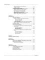
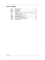
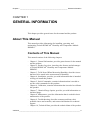
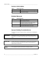
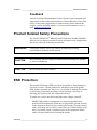
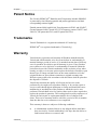
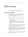
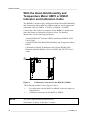
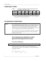
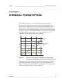
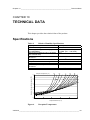
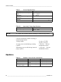
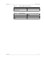
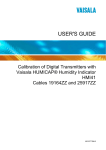
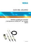
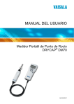
1
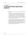
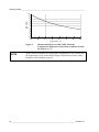
USER'S GUIDE ® Vaisala HUMICAP Humidity and Temperature Module HMM213 U339EN-1.3 PUBLISHED BY Vaisala Oyj P.O. Box 26 FI-00421 Helsinki Finland Phone (int.): +358 9 8949 1 Fax: +358 9 8949 2227 Visit our Internet pages at http://www.vaisala.com/ © Vaisala 2009 No part of this manual may be reproduced in any form or by any means, electronic or mechanical (including photocopying), nor may its contents be communicated to a third party without prior written permission of the copyright holder. The contents are subject to change without prior notice. Please observe that this manual does not create any legally binding obligations for Vaisala towards the customer or end user. All legally binding commitments and agreements are included exclusively in the applicable supply contract or Conditions of Sale. ________________________________________________________________________________ Table of Contents CHAPTER 1 GENERAL INFORMATION............................................................................ 9 About This Manual ................................................................... 9 Contents of This Manual ....................................................... 9 Version Information ............................................................. 10 Related Manuals ................................................................. 10 General Safety Considerations ........................................... 10 Feedback............................................................................. 11 Product Related Safety Precautions .................................... 11 ESD Protection ....................................................................... 11 Recycling ................................................................................ 12 Regulatory Compliances ....................................................... 12 Patent Notice .......................................................................... 13 Trademarks ............................................................................. 13 Warranty.................................................................................. 13 CHAPTER 2 PRODUCT OVERVIEW................................................................................ 15 Introduction to HMM213 ........................................................ 15 CHAPTER 3 TO BE NOTED WHEN MEASURING HUMIDITY........................................ 17 CHAPTER 4 INSTALLATION............................................................................................ 19 Selecting Location ................................................................. 19 Electrical Connections........................................................... 19 Dimensions ............................................................................. 20 Serial Bus Settings................................................................. 20 CHAPTER 5 SERIAL COMMANDS .................................................................................. 21 Output via the Serial Bus....................................................... 21 R Starting the Measurement Output ................................... 21 S Stopping the Measurement Output.................................. 21 SEND Outputting a Reading Once ..................................... 22 INTV Setting the Output Interval for the RUN State ........... 22 SERI Serial Bus Settings .................................................... 23 ADDR Setting the Device Address ..................................... 23 UNIT Selecting the Output Units ......................................... 24 VERS Displaying Software Version .................................... 24 RESET Resetting the Transmitter....................................... 24 Operating via the Serial Bus ................................................. 25 VAISALA ________________________________________________________________________ 3 USER'S GUIDE____________________________________________________________________ SMODE Setting the Serial Interface....................................25 OPEN & CLOSE..................................................................25 Setting the Output Format .....................................................26 MCR Setting the Carriage Return On/Off............................26 MDEC Selecting a Decimal Separator ................................26 MFLD Selecting a Field Separator ......................................27 MLF Setting the Line Feed On/Off ......................................27 MSPC Setting Spaces On/Off .............................................28 MSYMB Setting Variable Symbols On/Off ..........................28 MUNIT Setting Variable Units On/Off..................................29 CHAPTER 6 CALIBRATION .............................................................................................31 Humidity Calibration ..............................................................32 Humidity Calibration with Serial Commands .......................32 Two-Point Calibration .....................................................32 One Point Calibration .....................................................33 Gain Calibration..............................................................33 With the Hand-Held Humidity and Temperature Meter HM70 or HMI41 Indicator and Calibration Cable ................34 Calibration Table ....................................................................36 Temperature Calibration ........................................................36 CT Temperature Calibration of the Warmed Humidity Sensor Head........................................................................36 Two Point Calibration .....................................................36 One Point Calibration .....................................................37 Gain Calibration..............................................................37 CT Temperature Calibration of the Additional Sensor Head ....................................................................................38 Two Point Calibration .....................................................38 One Point Calibration .....................................................39 Gain Calibration..............................................................39 CHAPTER 7 CHEMICAL PURGE OPTION.......................................................................41 CHAPTER 8 MAINTENANCE............................................................................................43 Replacing the HUMICAP®180R Sensor and the Filter.........43 Replacing Consumables........................................................43 Parts List for Consumables .................................................43 CHAPTER 9 TROUBLESHOOTING..................................................................................45 Troubleshooting Procedure ..................................................45 Technical Support ..................................................................45 Return Instructions ................................................................46 Vaisala Service Centers .........................................................47 4 _____________________________________________________________________ U339EN-1.3 ________________________________________________________________________________ CHAPTER 10 TECHNICAL DATA ...................................................................................... 49 Specifications ......................................................................... 49 Options .................................................................................... 50 VAISALA ________________________________________________________________________ 5 USER'S GUIDE____________________________________________________________________ List of Figures Figure 1 Figure 2 Figure 3 Figure 4 Figure 5 Figure 6 Measurement Error at 100 %RH when the Temperature Difference between the Ambient Air and the Sensor is 1 °C....18 Electrical Connections ..............................................................19 Dimensions in mm (inches) ......................................................20 Calibration Connector for the HM70 or HMI41 .........................34 Decrease of the Sensor Gain Due to an Interfering Chemical and the Effect of the Chemical Purge Process.........................41 Dewpoint Temperature .............................................................49 6 _____________________________________________________________________ U339EN-1.3 ________________________________________________________________________________ List of Tables Table 1 Table 2 Table 3 Table 4 Table 5 Table 6 Table 7 Table 8 Table 9 Table 10 Table 11 Table 12 Table 13 Manual Revisions ..................................................................... 10 Related Manuals ...................................................................... 10 Emission Tests ......................................................................... 12 Immunity Tests ......................................................................... 12 Output Units ............................................................................. 24 Greenspan's Calibration Table with Output Values According to the Chosen Scale ................................................................. 36 Available Spare Parts............................................................... 43 Relative Humidity Specifications .............................................. 49 General Specifications ............................................................. 50 Operating Voltage Specifications ............................................. 50 Modules, Sensor Heads and Outputs ...................................... 50 Cable Lengths for Sensor Heads ............................................. 51 Chemical Purge........................................................................ 51 VAISALA ________________________________________________________________________ 7 USER'S GUIDE____________________________________________________________________ This page intentionally left blank. 8 _____________________________________________________________________ U339EN-1.3 Chapter 1 ________________________________________________________ General Information CHAPTER 1 GENERAL INFORMATION This chapter provides general notes for the manual and the product. About This Manual This manual provides information for installing, operating, and maintaining Vaisala HUMICAP® Humidity and Temperature Module HMM213. Contents of This Manual This manual consists of the following chapters: - Chapter 1, General Information, provides general notes for the manual and the product. - Chapter 2, Product Overview, introduces the features and advantages of Vaisala HUMICAP® Humidity and Temperature Module HMM213. - Chapter 3, To Be Noted When Measuring Humidity, describes issues that need to be noted in the measurement of humidity. - Chapter 4, Installation, provides you with information that is intended to help you install this product. - Chapter 5, Serial Commands, contains information that is needed to use the serial commands for this product. - Chapter 6, Calibration, contains information that is needed to calibrate this product. - Chapter 7, Chemical Purge Option, provides you with information on chemical purge. - Chapter 8, Maintenance, provides information that is needed in basic maintenance of the product. - Chapter 9, Troubleshooting, describes common problems, their probable causes and remedies, and contact information for technical support. - Chapter 10, Technical Data, provides the technical data of the product. VAISALA ________________________________________________________________________ 9 USER'S GUIDE____________________________________________________________________ Version Information Table 1 Manual Code U339EN-1.2 U339EN-1.3 Manual Revisions Description October 1999 This manual, December 2009 - HUMICAP® sensor type has been changed. Related Manuals Table 2 Manual Code M210316EN-A M210777EN-B M210185EN-C M210297EN-E Related Manuals Manual Name Vaisala HUMICAP® Indicator HMI41 and Probes HMP41/45/46 User's Guide Calibration of Digital Transmitters with Vaisala HUMICAP® Humidity Indicator HMI41 Cables 19164ZZ and 25917ZZ User's Guide Vaisala Humidity Calibrator HMK15 User's Guide Vaisala HUMICAP® Hand-Held Humidity and Temperature Meter HM70 User's Guide General Safety Considerations Throughout the manual, important safety considerations are highlighted as follows: WARNING Warning alerts you to a serious hazard. If you do not read and follow instructions very carefully at this point, there is a risk of injury or even death. CAUTION Caution warns you of a potential hazard. If you do not read and follow instructions carefully at this point, the product could be damaged or important data could be lost. NOTE Note highlights important information on using the product. 10 ____________________________________________________________________ U339EN-1.3 Chapter 1 ________________________________________________________ General Information Feedback Vaisala Customer Documentation Team welcomes your comments and suggestions on the quality and usefulness of this publication. If you find errors or have other suggestions for improvement, please indicate the chapter, section, and page number. You can send comments to us by email: [email protected] Product Related Safety Precautions The Vaisala HUMICAP® Humidity and Temperature Module HMM213 delivered to you has been tested for safety and approved as shipped from the factory. Note the following precautions: WARNING Ground the product, and verify outdoor installation grounding periodically to minimize shock hazard. CAUTION Do not modify the unit. Improper modification can damage the product or lead to malfunction. CAUTION Do not touch the sensor element. ESD Protection Electrostatic Discharge (ESD) can cause immediate or latent damage to electronic circuits. Vaisala products are adequately protected against ESD for their intended use. However, it is possible to damage the product by delivering electrostatic discharges when touching, removing, or inserting any objects inside the equipment housing. To make sure you are not delivering high static voltages yourself: - Handle ESD sensitive components on a properly grounded and protected ESD workbench. When this is not possible, ground yourself to the equipment chassis before touching the boards. Ground yourself with a wrist strap and a resistive connection cord. When neither of the above is possible, touch a conductive part of the equipment chassis with your other hand before touching the boards. VAISALA _______________________________________________________________________ 11 USER'S GUIDE____________________________________________________________________ - Always hold the boards by the edges and avoid touching the component contacts. Recycling Recycle all applicable material. Dispose of batteries and the unit according to statutory regulations. Do not dispose of with regular household refuse. Regulatory Compliances The Vaisala HUMICAP® Humidity and Temperature Module HMM213 complies with the following performance and environmental test standards: The emission and immunity tests have been performed according to standard EN61326-1. Table 3 Emission Tests Test RF field emission Conducted emissions Table 4 Setup According to CISPR 22 Class B (EN55022) CISPR 22 B (EN55022) Immunity Tests Test Electrostatic discharge Fast transient burst RF field immunity Conducted RF immunity NOTE: cable length max. 8 meters Surge Voltage dips, short interrupts Setup According to IEC 1000-4-2 (EN 61000-4-2) IEC 1000-4-4 (EN 61000-4-4) IEC 1000-4-3 (EN 61000-4-3) IEC 1000-4-6 (EN 61000-4-6) IEC 1000-4-5 (EN 61000-4-5) IEC 1000-4-11 (EN 61000-4-11) 12 ____________________________________________________________________ U339EN-1.3 Chapter 1 ________________________________________________________ General Information Patent Notice The Vaisala HUMICAP® Humidity and Temperature Module HMM213 is protected by the following patents and patent applications and their corresponding national rights: Finnish patents 98861 and 99164, French patents 6650303 and 9504397, German patents 69418174 and 19513274, Japanese patents 3585973 and 2801156, UK patent 0665303, and US patent 5607564. Trademarks Vaisala Trademark is a registered trademark of Vaisala Oyj. HUMICAP® is a registered trademark of Vaisala Oyj. Warranty Vaisala hereby represents and warrants all Products manufactured by Vaisala and sold hereunder to be free from defects in workmanship or material during a period of twelve (12) months from the date of delivery save for products for which a special warranty is given. If any Product proves however to be defective in workmanship or material within the period herein provided Vaisala undertakes to the exclusion of any other remedy to repair or at its own option replace the defective Product or part thereof free of charge and otherwise on the same conditions as for the original Product or part without extension to original warranty time. Defective parts replaced in accordance with this clause shall be placed at the disposal of Vaisala. Vaisala also warrants the quality of all repair and service works performed by its employees to products sold by it. In case the repair or service works should appear inadequate or faulty and should this cause malfunction or nonfunction of the product to which the service was performed Vaisala shall at its free option either repair or have repaired or replace the product in question. The working hours used by employees of Vaisala for such repair or replacement shall be free of charge to the client. This service warranty shall be valid for a period of six (6) months from the date the service measures were completed. This warranty is however subject to following conditions: a) A substantiated written claim as to any alleged defects shall have been received by Vaisala within thirty (30) days after the defect or fault became known or occurred, and VAISALA _______________________________________________________________________ 13 USER'S GUIDE____________________________________________________________________ b) the allegedly defective Product or part shall, should Vaisala so require, be sent to the works of Vaisala or to such other place as Vaisala may indicate in writing, freight and insurance prepaid and properly packed and labelled, unless Vaisala agrees to inspect and repair the Product or replace it on site. This warranty does not however apply when the defect has been caused through a) b) c) d) e) normal wear and tear or accident; misuse or other unsuitable or unauthorized use of the Product or negligence or error in storing, maintaining or in handling the Product or any equipment thereof; wrong installation or assembly or failure to service the Product or otherwise follow Vaisala's service instructions including any repairs or installation or assembly or service made by unauthorized personnel not approved by Vaisala or replacements with parts not manufactured or supplied by Vaisala; modifications or changes of the Product as well as any adding to it without Vaisala's prior authorization; other factors depending on the Customer or a third party. Notwithstanding the aforesaid Vaisala's liability under this clause shall not apply to any defects arising out of materials, designs or instructions provided by the Customer. This warranty is expressly in lieu of and excludes all other conditions, warranties and liabilities, express or implied, whether under law, statute or otherwise, including without limitation ANY IMPLIED WARRANTIES OF MERCHANTABILITY OR OF FITNESS FOR A PARTICULAR PURPOSE and all other obligations and liabilities of Vaisala or its representatives with respect to any defect or deficiency applicable to or resulting directly or indirectly from the Products supplied hereunder, which obligations and liabilities are hereby expressly cancelled and waived. Vaisala's liability shall under no cir-cumstances exceed the invoice price of any Product for which a warranty claim is made, nor shall Vaisala in any circumstances be liable for lost profits or other consequential loss whether direct or indirect or for special damages. 14 ____________________________________________________________________ U339EN-1.3 Chapter 2 __________________________________________________________ Product Overview CHAPTER 2 PRODUCT OVERVIEW This chapter introduces the features and advantages of Vaisala HUMICAP® Humidity and Temperature Module HMM213. Introduction to HMM213 The HMM213 modules are designed especially for relative humidity measurements in environmental chamber applications with high temperature and humidity levels. They also measure temperature and calculate the dewpoint temperature. The HMM213 has actually three different module options to choose from: - Humidity and temperature module: with a standard humidity and temperature sensor head - Dewpoint module with a warmed sensor head incorporating a composite RH and T sensor - Humidity and temperature module with two sensor heads: with a warmed humidity sensor head incorporating a composite sensor, and an additional temperature sensor head for ambient temperature measurement The HMM213 is a RS232 serial output module. The customer has two options for the humidity probe length. Furthermore, the module can also be ordered with a suitable cable length (0.65 m, 1.50 m, or 3.0 m). The temperature measurement range is -70 ... +180 °C). Output parameters depend on the module type. The output parameters for the RH and T module are relative humidity and temperature. For the RH and T module with two sensor heads, the parameters also include relative humidity and temperature and for the dewpoint module, the parameter is dewpoint temperature. The dewpoint temperature range is -70 ... +100 °C. The probes also have a selectable chemical purge option. Note that with a warmed sensor head, the probe length is always 90 mm and the sensor is protected with a sintered filter. VAISALA _______________________________________________________________________ 15 USER'S GUIDE____________________________________________________________________ The HMM213 modules are connected to process control systems with screw terminals. These versatile modules incorporate the HUMICAP®180R humidity sensor, which uses an operating principle based on changes in the capacitance of a thin polymer film as it absorbs water molecules. The HMM213 modules measure temperature with the reliable Pt 100 sensor. If the module is ordered with chemical purge option, it incorporates a composite sensor. 16 ____________________________________________________________________ U339EN-1.3 Chapter 3 ________________________________________ To Be Noted When Measuring Humidity CHAPTER 3 TO BE NOTED WHEN MEASURING HUMIDITY This chapter describes issues that need to be noted in the measurement of humidity. In the measurement of relative humidity and especially in calibration, it is essential that the temperature equilibrium is reached. Even a slight difference in the temperature between the measured object and the sensor causes an error. For example, at +20 °C (+ 68 °F) and 50 %RH, a temperature difference of ±1 °C between the measured object and the sensor causes an error of ±3 %RH. If relative humidity is 90 %RH, the error is about ±5.4 %RH. A graph of the measurement error at 100 %RH when the temperature difference between ambient air and the sensor is 1 °C is presented in Figure 1 on page 18. The error is at its greatest when the temperature of the sensor differs from that of the surroundings and the humidity is high. A difference of a few degrees in temperature may cause water to condense on the sensor surface. Efficient ventilation accelerates the evaporation of the condensed water whereas in an unventilated space, it may take hours. The HUMICAP®180R sensor returns to its normal functioning as soon as water has evaporated. Contaminated water condensing on the sensor may shorten its life span and alter the calibration. VAISALA _______________________________________________________________________ 17 USER'S GUIDE____________________________________________________________________ 10 9 8 dRH (%RH) 7 6 5 4 3 2 1 0 -40 -20 0 20 40 60 80 100 Temperature (°C) Figure 1 NOTE Measurement Error at 100 %RH when the Temperature Difference between the Ambient Air and the Sensor is 1 °C With a dewpoint module, the temperature equilibrium is not a problem as the temperature of the sensor head changes continuously and the sensor head has a fast humidity response. 18 ____________________________________________________________________ U339EN-1.3 Chapter 4 _______________________________________________________________ Installation CHAPTER 4 INSTALLATION This chapter provides you with information that is intended to help you install this product. Selecting Location Finding a suitable site for HMM213 is important for getting representative ambient measurements Select a place that gives a true picture of the environment or process and is as clean as possible. Air should flow freely around the sensor head. Install the sensor head to a sufficient distance from the duct or chamber walls. Make sure to insert enough cable to the same space with the probe in order to prevent heat conduction. If an additional temperature probe is used, install it so that the warmed sensor head does not interfere with the measurement. Electrical Connections The HMM213 module is connected to a process control system with screw terminals. The wiring diagram is shown in Figure 2 below. RX TX Terminal 12-35VDC Figure 2 GND GND RX + X1 TX Us GND Electrical Connections VAISALA _______________________________________________________________________ 19 USER'S GUIDE____________________________________________________________________ Dimensions 1 (0. 4) 2 1.0 6( 2) ~6 5 Figure 3 (2 . 56 ) Dimensions in mm (inches) Serial Bus Settings The serial communication parameters set at factory are: Parameter Baud Parity Data bits Stop bits Value 1200 None 8 1 20 ____________________________________________________________________ U339EN-1.3 Chapter 5 __________________________________________________________ Serial Commands CHAPTER 5 SERIAL COMMANDS This chapter contains information that is needed to use the serial commands for this product. Output via the Serial Bus R Starting the Measurement Output R <cr> Starts output of measurements to the peripheral devices (PC display or printer); output interval is set with command INTV. The output format depends on the transmitter configuration and parameters in use. The order, however, is always the same: relative humidity, temperature, and dewpoint. An example: RH 43.0 %RH T 21.0 'C Tdp 8.0 'C <cr><lf> When the transmitter sends out the readings, the serial interface does not echo any commands; the only command that can be used is S (stop). S Stopping the Measurement Output S<cr> Ends the RUN state; after this command all other commands can be used. VAISALA _______________________________________________________________________ 21 USER'S GUIDE____________________________________________________________________ SEND Outputting a Reading Once SEND <cr> in STOP state or SEND aa <cr> in POLL state aa = address of the transmitter when more than one transmitter is connected to a serial bus (0 ... 99; set with command ADDR) Outputs the current measurement readings via the serial line. The output format depends on which parameters the transmitter can output. Output types are: "RH 32.25 %RH T 25.74 'C ",<cr><lf> "Td 7.93 'C",<cr><lf> INTV Setting the Output Interval for the RUN State INTV xxx yyy <cr> xxx = yyy = output interval (0 ... 255) 0: no pause between outputs unit (s, min or h) Sets the output interval when the transmitter outputs measurement readings to a peripheral device. For example: >INTV 10 MIN<cr> Output intrv. : 10 min 22 ____________________________________________________________________ U339EN-1.3 Chapter 5 __________________________________________________________ Serial Commands SERI Serial Bus Settings SERI b p d s <cr> b= bauds (150, 300, 600, 1200*, 2400, 4800) p= parity (n = none*, e = even, o = odd) d= data bits (7 or 8*) s= stop bits (1* or 2) * factory setting Giving the plain command outputs the current settings: >SERI <cr> Communication parameters > : 1200 N 8 1 Example of changing the serial bus settings: >seri 1200 e 7 1 Communication parameters : 1200 E 7 1 Set terminal settings accordingly > ADDR Setting the Device Address ADDR x x= 0 ... 99 The command is used to give an address for one device. The address is necessary for communication with a specific transmitter in POLL mode, when there are several modules connected to one serial bus >ADDR 11 Address > : 11 VAISALA _______________________________________________________________________ 23 USER'S GUIDE____________________________________________________________________ UNIT Selecting the Output Units UNIT x <cr> x= m(etric units) or n(on-metric units) Table 5 Output Units Metric Units %RH C C RH T Td Non-Metric Units %RH F F For example, the command for setting the non-metric units is: >UNIT N <cr> Unit > : non metric When the command is given with no parameters, the transmitter outputs the currently valid setting. VERS Displaying Software Version VERS >VERS HMM213 > 1.03 RESET Resetting the Transmitter RESET <cr> Resets the transmitter. All settings that have been changed stay in the memory even after reset or power failure. 24 ____________________________________________________________________ U339EN-1.3 Chapter 5 __________________________________________________________ Serial Commands Operating via the Serial Bus SMODE Setting the Serial Interface SMODE xxxx<cr> xxxx = In STOP mode: In RUN mode: In POLL mode: STOP, RUN or POLL measurements output only by command, all commands can be used outputting automatically, only command S can be used measurements output only with command SEND. When in POLL mode, the output state is changed as follows: OPEN aa <cr> SMODE xxxx<cr> aa = xxxx = address of the transmitter STOP, RUN or POLL The OPEN command sets the bus temporarily in STOP MODE so that the SMODE command can be given. For example: >SMODE Output >SMODE Output > (which mode is in use at the moment) : STOP (setting STOP mode) : STOP <cr> mode STOP <cr> mode OPEN & CLOSE OPEN nn <cr> nn = address of the transmitter (0 ... 99) CLOSE <cr> In STOP mode: In POLL mode: command OPEN has no effect, CLOSE sets the transmitter in POLL mode command OPEN sets the transmitter temporarily in STOP mode, command CLOSE returns the instrument to POLL mode VAISALA _______________________________________________________________________ 25 USER'S GUIDE____________________________________________________________________ When more than one transmitter is connected to the same serial bus, the POLL mode makes it possible to communicate with the transmitters. For example, a relative humidity calibration is performed at transmitter 2 (<bel> = ASCII 7): >OPEN 2 <cr> <cr><lf> 'HMM nn line opened for operator commands' <cr><lf><bel> >CRH <cr> ... >CLOSE <cr> <cr><lf><lf> 'line closed' <cr><lf> Setting the Output Format MCR Setting the Carriage Return On/Off MCR x x= ON/OFF >MCR ON Msg. cr > : ON MDEC Selecting a Decimal Separator MDEC x x= a character, TAB, SP, CR, LF >MDEC . dec. separator >R RH 60.50 %RH RH 60.50 %RH ... >MDEC Z dec. separator >R RH 60Z56 %RH RH 60Z56 %RH ... > : . T 23.90 'C T 23.90 'C : Z T 23Z89 'C T 23Z90 'C 26 ____________________________________________________________________ U339EN-1.3 Chapter 5 __________________________________________________________ Serial Commands MFLD Selecting a Field Separator MFLD x x= a character, TAB, SP, CR, LF >MFLD SP fld. separator >R RH 60.53 %RH T 23.89 'C RH 60.52 %RH T 23.89 'C ... >MFLD TAB fld. separator >R RH 60.58 %RH RH 60.57 %RH ... : SP : TAB T 23.89 'C T 23.89 'C MLF Setting the Line Feed On/Off MLF x x= ON/OFF >MLF OFF Msg. lf >R >RH 60.78 %RH >MLF ON Msg. lf >R RH 60.85 %RH RH 60.80 %RH ... : OFF T 23.84 'C (repeating values) : ON T 23.86 'C T 23.86 'C VAISALA _______________________________________________________________________ 27 USER'S GUIDE____________________________________________________________________ MSPC Setting Spaces On/Off MSPC x x= ON/OFF MSPC sets on/off the outputting of a space before and after the values of the message. >MSPC OFF Msg. space >R RH57.52%RH RH57.50%RH RH57.44%RH >MSPC ON Msg. space >R RH 57.55 %RH RH 57.55 %RH RH 57.48 %RH > : OFF T73.81'F T73.77'F T73.76'F : ON T 73.78 'F T 73.78 'F T 73.82 'F MSYMB Setting Variable Symbols On/Off MSYMB x x= ON/OFF >MSYMB ON Msg. symbol >R RH 60.86 %RH RH 60.86 %RH ... >MSYMB OFF Msg. symbol >R 60.91 %RH 60.84 %RH ... : ON T 23.87 'C T 23.87 'C : OFF 23.87 'C 23.87 'C 28 ____________________________________________________________________ U339EN-1.3 Chapter 5 __________________________________________________________ Serial Commands MUNIT Setting Variable Units On/Off MUNIT x x= ON/OFF >MUNIT ON Msg. unit >R RH 61.01 %RH RH 60.99 %RH ... >MUNIT OFF Msg. unit >R RH 60.97 RH 60.98 ... > : ON T 23.85 'C T 23.85 'C : OFF T 23.84 T 23.87 VAISALA _______________________________________________________________________ 29 USER'S GUIDE____________________________________________________________________ This page intentionally left blank. 30 ____________________________________________________________________ U339EN-1.3 Chapter 6 _______________________________________________________________ Calibration CHAPTER 6 CALIBRATION This chapter contains information that is needed to calibrate this product. Vaisala recommends a recalibration of the HMM213 module after six months of use. After the first recalibration, the recommended calibration interval is approximately 12 months. However, please note that these intervals depend on the operating conditions and the required accuracy. When calibrating humidity instruments, it is important that the probe, the reference instrument, and the calibrator are in thermal equilibrium. Therefore, always allow enough time for stabilization before starting the actual calibration. - Calibration in the chamber: leave the calibrator (for example, the HMK15) in the chamber overnight with the chamber door open. - Calibration of a humidity and temperature module: allow at least one hour for the stabilization of the calibrator (for example, HM70 handheld humidity and temperature meter with a reference probe). - Calibration of a dewpoint module or of a humidity and temperature module with two sensor heads: allow at least 3 hours for stabilization if the sensor head is in such an environment that the warming function has been active. - Calibration of a module with chemical purge option: chemical purge is activated when the power is connected. When calibrating a probe, turn the power on with the sintered stainless steel filter on the probe, wait for 10 minutes, and remove the filter. Let stabilize and perform a calibration. NOTE: do not turn the power off during calibration. NOTE When calibrating a module with the warmed sensor head, deactivate first the heating by using command HEAT 0 <cr>. If the sensor head is in such an environment that the warming function has been active, allow at least 3 hours for stabilization. After calibration, the heating is reactivated with command HEAT 1 <cr>. VAISALA _______________________________________________________________________ 31 USER'S GUIDE____________________________________________________________________ Humidity Calibration A one-point calibration can be done against an accurate transfer standard in the field and a two-point calibration using saturated salt solutions in controlled conditions (HMK15). You can also send the instrument to Vaisala or a Vaisala representative for recalibration. Humidity Calibration with Serial Commands Two-Point Calibration CRH <cr> With this command, the transmitters can be calibrated at two humidity points against a reference. An example of performing the two point calibration with the HMK15: 1. 2. 3. Leave the calibrator and the probe for at least 1 hour in the same environment so that their temperatures have time to equalize. Remove the sintered filter and insert the probe into the measurement hole of the LiCl salt chamber in the humidity calibrator. Give the command CRH and the following text appears: >CRH <cr> RH : 12.00 4. Wait for 20 to 40 minutes. If the stabilization of the sensor to the humidity in the calibrator needs to be monitored, the measurement output can be repeated by <cr> at Ref1 and Ref2. >CRH <cr> RH : 12.00 RH : 11.70 RH : 11.50 ... 5. Ref1 ? Ref1 ? <cr> Ref1 ? <cr> Ref1 ? <cr> Check the temperature and read the closest corresponding RH value in the calibration table. Give the value and acknowledge it with enter. RH : 12.00 Ref1 ? 11.3 <cr> Press any key when ready ... 32 ____________________________________________________________________ U339EN-1.3 Chapter 6 _______________________________________________________________ Calibration 6. 7. Insert the probe into the measurement hole of the NaCl chamber. Wait for 20 to 40 minutes. Check the temperature and read the closest corresponding RH value in the calibration table. Give the value and acknowledge it with enter. RH > 8. : 76.00 Ref2 ? 75.5 <cr> Check again the reading at the first point and repeat the procedure if necessary. One Point Calibration CRH xx.xx yy.yy xx.xx = yy.yy = current humidity offset calibration Example of performing the offset calibration in one reference point: >crh 54.63 2.3 > Use an accurate and calibrated reference only. Gain Calibration CRH 0 0 xx.xx yy.yy xx.xx = current humidity yy.yy = correction (RHref-RHmeasured) Example of performing the gain calibration in one reference point: >crh 0 0 73.60 1.7 > Use an accurate and calibrated reference only. VAISALA _______________________________________________________________________ 33 USER'S GUIDE____________________________________________________________________ With the Hand-Held Humidity and Temperature Meter HM70 or HMI41 Indicator and Calibration Cable The HMM213 module can be calibrated with the Hand-Held Humidity and Temperature Meter HM70 or HMI41 indicator and an appropriate calibration cable (for HM70: 27159ZZ; for HMI41: 19164ZZ). Connect the cable to the test connector of the HMM213 module and insert the jumper as indicated in Figure 4 below. For detailed instructions, see the following documents: - Vaisala HUMICAP® Indicator HMI41 and Probes HMP41/45/46 User's Guide - Vaisala HUMICAP® Hand-Held Humidity and Temperature Meter HM70 - Calibration of Digital Transmitters with Vaisala HUMICAP® Humidity Indicator HMI41 Cables 19164ZZ and 25917ZZ User's Guide 2 1 Figure 4 Calibration Connector for the HM70 or HMI41 The following numbers refer to Figure 4 above: 1 = For calibration with the HM70 or HMI41, insert the jumper as indicated here. 2 = Calibration connector for the HM70 or HMI41 NOTE The serial communication parameters are: 1200 bauds, no parity, 8 data bits, 1 stop bit 34 ____________________________________________________________________ U339EN-1.3 Chapter 6 _______________________________________________________________ Calibration NOTE When the connection is being established, the message 'CON ERROR' blinks on the HMI41 display for a couple of times after which measurement readings appear. This is quite normal and requires no action; however, if the message is not replaced by measurement readings, it is an indication of an operation error. VAISALA _______________________________________________________________________ 35 USER'S GUIDE____________________________________________________________________ Calibration Table Table 6 Greenspan's Calibration Table with Output Values According to the Chosen Scale Temperature °C °F LiCl %RH NaCl %RH *) 15 59 *) 75.6 20 68 11.3 75.5 25 77 11.3 75.3 30 86 11.3 75.1 35 95 11.3 74.9 If the LiCl solution is used or stored in temperatures below +18 °C (+64 °F), the equilibrium humidity of the salt solution may change permanently. Temperature Calibration NOTE The temperature channel of the HMM213 is very stable and the modules have been calibrated at the factory. Unless there is a strong reason to believe that the adjustments have changed, do not perform a temperature calibration. This is a very demanding procedure and requires both expertise and extremely accurate references. Furthermore, it is important to allow enough time for the stabilization during calibration. If for some reason it is necessary to perform the temperature calibration, follow attentively the instructions given below. Use an accurate and calibrated reference only. CT Temperature Calibration of the Warmed Humidity Sensor Head Two Point Calibration CT <cr> Using this command the transmitters can be calibrated against an accurate reference, such as a Pt 100 simulator. A two-point calibration is performed as follows: >CT <cr> T : 23.22 Ref1 ? 23.3 <cr> Press any key when ready ... T : 101.42 Ref2 ? 101 <cr> 36 ____________________________________________________________________ U339EN-1.3 Chapter 6 _______________________________________________________________ Calibration If the stabilization of the sensor to the temperature of the reference needs to be monitored, the measurement output can be repeated with <cr> at Ref1 and Ref2: >CTA <cr> T : 23.19 Ref1 ? <cr> T : 23.20 Ref1 ? <cr> . . . T : 23.22 Ref1 ? 23.3 <cr> Press any key when ready ... T : 101.42 Ref2 ? 101 <cr> One Point Calibration CT xx.xx yy.yy xx.xx = current temperature yy.yy = offset correction Example of performing the offset calibration in one reference temperature: >CT 21.2 2.3 > Use an accurate and calibrated reference only. Gain Calibration CT xx 0 yy.yy zz.zz xx = temperature in which there is no changes in offset yy.yy = current temperature zz.zz = correction (Tref-Tmeasured) Example of performing the gain calibration in one reference point without changing the offset at 0 °C: >CT 0 0 101 -0.5 > Example of performing the gain calibration in one reference point without changing the offset at -70 °C: VAISALA _______________________________________________________________________ 37 USER'S GUIDE____________________________________________________________________ >CT -70 0 101 -0.5 > Use an accurate and calibrated reference only. CT Temperature Calibration of the Additional Sensor Head Two Point Calibration CTA <cr> Using this command the transmitters can be calibrated against an accurate reference, such as a Pt 100 simulator. A two-point calibration is performed as follows: >CTA <cr> T : 23.19 Ref1 ? 23.3 <cr> Press any key when ready ... T : 101.42 Ref2 ? 101 <cr> If the stabilization of the sensor to the temperature of the reference needs to be monitored, the measurement output can be repeated with <cr> at Ref1 and Ref2: >CTA <cr> T : 23.19 Ref1 ? <cr> T : 23.20 Ref1 ? <cr> . . . T : 23.22 Ref1 ? 23.3 <cr> Press any key when ready ... T : 101.42 Ref2 ? 101 <cr> 38 ____________________________________________________________________ U339EN-1.3 Chapter 6 _______________________________________________________________ Calibration One Point Calibration CTA xx.xx yy.yy xx.xx = current temperature yy.yy = offset correction Example of performing the offset calibration in one reference temperature: >CTA 21.2 2.3 > Use an accurate and calibrated reference only. Gain Calibration CTA xx 0 yy.yy zz.zz xx = temperature in which there is no changes in offset yy.yy = current temperature zz.zz = correction (Tref-Tmeasured) Example of performing the gain calibration in one reference point without changing the offset at 0 °C: >CTA 0 0 101 -0.5 > Example of performing the gain calibration in one reference point without changing the offset at -70 °C: >CTA -70 0 101 -0.5 > Use an accurate and calibrated reference only. VAISALA _______________________________________________________________________ 39 USER'S GUIDE____________________________________________________________________ This page intentionally left blank. 40 ____________________________________________________________________ U339EN-1.3 Chapter 7 ______________________________________________________Chemical Purge Option CHAPTER 7 CHEMICAL PURGE OPTION This chapter provides you with information on chemical purge. In some applications, the sensor gain may decrease gradually due to interference caused by some chemical present in the ambient air (see Figure 5 below). The sensor polymer absorbs the interfering chemical; this reduces its water absorption ability and so decreases the sensor gain. In chemical purge, the interfering chemical is evaporated by heating the humidity sensor to a temperature level of approximately +160 °C. Automatic chemical purge takes place at startup. Calibration values Chemical purge Output signal Measured values after chemical exposure Humidity Figure 5 Decrease of the Sensor Gain Due to an Interfering Chemical and the Effect of the Chemical Purge Process The sensor with chemical purge option is a composite sensor in which the HUMICAP® and Pt 100 temperature sensors are attached to each other. Chemical purge option requires that the sensor is protected with a stainless steel sintered filter (part no. HM46670). VAISALA _______________________________________________________________________ 41 USER'S GUIDE____________________________________________________________________ This page intentionally left blank. 42 ____________________________________________________________________ U339EN-1.3 Chapter 8 ______________________________________________________________ Maintenance CHAPTER 8 MAINTENANCE This chapter provides information that is needed in basic maintenance of the product. Replacing the HUMICAP®180R Sensor and the Filter Remove the damaged sensor and insert a new one. Handle the sensor by the plastic socket. Recalibrate the transmitter. CAUTION Do not touch the sensor element. Replace a dirty filter to ensure a maximum lifetime and a fast response for the sensor. Replacing Consumables This section describes how to replace consumables. Parts List for Consumables Table 7 Available Spare Parts Spare Part HUMICAP®180R Sensor Stainless steel sintered filter Order Code HUMICAP180R HM46670 VAISALA _______________________________________________________________________ 43 USER'S GUIDE____________________________________________________________________ This page intentionally left blank. 44 ____________________________________________________________________ U339EN-1.3 Chapter 9 ___________________________________________________________ Troubleshooting CHAPTER 9 TROUBLESHOOTING This chapter describes common problems, their probable causes and remedies, and contact information for technical support. Troubleshooting Procedure When troubleshooting the product, write a problem report consisting of the following issues: - What failed (what worked / did not work)? - Where did it fail (location and environment)? - When did it fail (date, immediately / after a while / periodically / randomly)? - How many failed (only one defect / other same or similar defects / several failures in one unit)? - What was connected to the product and to which connectors? - Input power source type, voltage and list of other items (lighting, heaters, motors etc.) that were connected to the same power output. - What was done when the failure was noticed? Technical Support For technical questions, contact the Vaisala technical support: E-mail [email protected] Fax +358 9 8949 2790 VAISALA _______________________________________________________________________ 45 USER'S GUIDE____________________________________________________________________ Return Instructions If the product needs repair, please follow the instructions below to speed up the process and to avoid extra costs to you. 1. 2. Read the section Warranty on page 13. Contact a Vaisala Service Center or a local Vaisala representative. The latest contact information and instructions are available from www.vaisala.com. Addresses of the Service Centers are provided in section Vaisala Service Centers on page 47. Please have the following information on hand: - 3. 4. 5. serial number of the unit date and place of purchase or last calibration description of the fault circumstances in which the fault occurs/occurred name and contact information of a technically competent person who can provide further information on the problem Pack the faulty product in a strong box of adequate size, with proper cushioning material to avoid damage. Include the information specified in step 2 in the box with the faulty product. Also include a detailed return address. Ship the box to the address specified by your Vaisala contact. 46 ____________________________________________________________________ U339EN-1.3 Chapter 9 ___________________________________________________________ Troubleshooting Vaisala Service Centers Vaisala Service Centers perform calibrations and adjustments as well as repair and spare part services. See contact information below. Vaisala Service Centers also offer accredited calibrations, maintenance contracts, and a calibration reminder program. Do not hesitate to contact them to get further information. VAISALA _______________________________________________________________________ 47 USER'S GUIDE____________________________________________________________________ This page intentionally left blank. 48 ____________________________________________________________________ U339EN-1.3 Chapter 10 ___________________________________________________________ Technical Data CHAPTER 10 TECHNICAL DATA This chapter provides the technical data of the product. Specifications Table 8 Relative Humidity Specifications Property Measurement range Accuracy (including non-linearity, hysteresis and repeatability) Response time (90%) at +20 °C in still air (with sintered filter) Typical temperature dependence of electronics Humidity sensor Temperature measurement range Typical accuracy of electronics at +20 °C Typical temperature dependence of electronics Temperature sensor Accuracy in dewpoint measurement (°C) -40 Dewpoint temperature (°C) 5 Description / Value 0 ... 100 %RH ±2 %RH (0 … 90 %RH ) ±3 %RH (90 … 100 %RH ) 60 s 0.02 %RH /°C HUMICAP®180R -70 ... +180 °C ±0.1 °C 0.0025 °C/°C Pt 100 RTD 1/3 IEC 751 Class B -20 0 20 40 60 4 80 100 3 2 1 0 0 20 40 60 80 100 Dewpoint difference (°C) Figure 6 Dewpoint Temperature VAISALA _______________________________________________________________________ 49 USER'S GUIDE____________________________________________________________________ Table 9 General Specifications Property Operating temperature range Probe Electronics Storage temperature range (electronics) Sensor protection: Standard Connections Table 10 -70 … +180 °C -5 … +55 °C -40 … +70 °C Stainless steel sintered filter Screw terminals for 0.5 ... 1.5 mm2 wires Operating Voltage Specifications Property Operating voltage NOTE Description / Value Value DC: 10 … 35 V AC: 9 … 24 V AC supply only possible without warming or chemical purge option. Current consumption without warming or chemical purge option Voltage output: Average power needed during warming (option) 12 mA at 35 VDC 20 mA at 24 VAC 1 W (100 … 300 mA modulated current) Maximum power needed during chemical purge (option): 1.4 W (100 … 300 mA modulated current) Options Table 11 Modules, Sensor Heads and Outputs Module RH and T module Dewpoint module RH and T module with two sensor heads Sensor Heads One sensor head Warmed humidity sensor head Warmed humidity sensor head Output RH and T output Dewpoint output RH and T output 50 ____________________________________________________________________ U339EN-1.3 Chapter 10 ___________________________________________________________ Technical Data Table 12 Cable Lengths for Sensor Heads Sensor Head Humidity sensor head Optional T sensor head/ module with two sensor heads Table 13 Cable Length 65, 150, 300 cm 150 or 300 cm Chemical Purge Module RH and T module Dewpoint module RH and T module with two sensor heads Automatic Chemical Purge at Startup Yes Yes Yes VAISALA _______________________________________________________________________ 51 www.vaisala.com *U339EN*