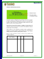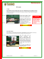
1
AIRSEEDER OPERATORS MANUAL Model: Serial No: Description: TQC2 6000 Options Small Seeds Box Trailing Castoring Quad, 6000 litre, 2 bin, Ground Drive Linear Actuator For Instruction On: Castoring Machine Configuration Linear Actuator Operation Eagle Controller Operation Small Seeds Box Operation Contents Section 1: Introduction Welcome to Simplicity Australia Company Profile Product Overview Page 1.1 1.2 1.3 Page 2.1 2.2 2.3 2.4 Page 3.1 Section 2: Safety Safety Instructions – ‘Key Words’ Location of Safety Decals – LHS and Rear Location of Safety Decals – RHS and Front Road and Field Travel Section 3: Operation Hooking up Filling and Emptying the Bins Filling Emptying Air Seeder Calibration Variable Seed Rate Control Overview Calibrating Sowing Rates Compaction Warning Calibrating Sowing Rates Tips for Calibrating Sowing Rates Calibration & Compaction Crank Handle Stowage Higher Sowing Rates Product Flow (Bridging) Variable Seed Rate Control Calibration Check Method Record of Check Method Results Air Delivery System Overview Setting the Blower Speed Checking Blower Speed Delivery Capacity and Calculating Delivery Rate Double or Triple Shooting and Splitting Description and Background Illustration ‘One Pass Application’ Plan View – Six Row Double Shoot Worksheet – Double or Triple Shooting and Splitting Use of Air Restrictors Use of Metering Unit Spool Covers Use of Canola Covers Blocking Air Streams not in Use Notes Calculating Bin Split Bin Split Plan Changing Bin Split Seeding Kit Terminology Seeding Kit Set Up Monitor Description Software and Hardware Version Simplicity Australia 3.2 3.3 3.4 3.5 – 3.6 3.6 3.7 3.7 3.8 3.8 3.9 – 3.10 3.10 3.11 3.12 3.13 3.13 3.14 3.15 3.16 3.17 3.18 3.19 3.20 3.20 3.21 3.22 3.23 3.24 3.25–3.28 3.29-3.30 3.31 3.32 Version 1.0 Contents Section 4: Maintenance Lubrication and Maintenance Overview Daily Checklist After Sowing Maintenance Lubrication and Maintenance Schedule Location of Grease Points and Lube Intervals Oil Levels Blower Maintenance Hydraulic Filter Replacement Clutch Maintenance Air Leak Check Service and Repair Records Notes Page 4.1 4.2 4.3 4.4 4.5 4.6 4.7 4.7, 4.8 4.8 4.9-4.12 4.13 4.14 Page 5.1, 5.2 5.3 5.4 Section 5: Troubleshooting Sowing Operation Blower Operation Notes Section 6: Miscellaneous Tyre Pressure Guide Useful Formulae Risk Assessment Notes Disclaimer Simplicity Australia Page 6.1 6.2 6.3 6.4 Rear cover Version 1.0 Introduction Welcome to Simplicity Australia The Management and Staff of Simplicity Australia would like to thank you and congratulate you on your decision to purchase a new Simplicity Air Seeder. The design of your Simplicity Air Seeder incorporates many innovative features to make your farming operations easier, more efficient, and as the name suggests, simpler. Your Simplicity Air Seeder has been designed and manufactured with the utmost care and pride. By following the operation instructions outlined in this Operator’s Manual you will have many years of trouble free operation. This Operator’s Instruction Manual has been prepared to familiarise you with the set up, calibration, operation and maintenance of your new Simplicity Air Seeder. By reading this Operator’s Instruction Manual thoroughly, the most efficient and trouble free operation of your Simplicity Air Seeder will be achieved. Simplicity Australia operates Australia wide through a professional agricultural equipment Dealer network which includes factory trained Sales and Service personnel. If you have any concerns with the operation and maintenance of your Simplicity Air Seeder your local selling Dealer will be able to assist you with advice, service and spare parts back up. Your Simplicity Australia Dealer will register your Simplicity Air Seeder for warranty according to the guidelines of the Simplicity Australia Warranty Policy document included in your warranty registration booklet. Please ensure you complete the warranty registration documents in conjunction with your Dealer when you first use your Simplicity Air Seeder. Your Dealer will then forward the necessary documentation to Simplicity Australia. Without the relevant documents your Simplicity Air Seeder cannot be registered for warranty. When ordering replacement parts for your Simplicity Air Seeder be sure to quote the serial number attached to the machine which is also recorded on the warranty registration certificate. The Management and Staff of Simplicity Australia sincerely wish you every success with your new Simplicity Air Seeder and are available to assist your Simplicity Australia Dealer should they require any specialist assistance. Yours faithfully David W. Law Managing Director Simplicity Australia Page 1.1 Version 1.0 Introduction Company Profile Simplicity Australia Pty Ltd designs and manufactures the most comprehensive and innovative range of Air Seeders and Tillage Equipment in Australia today. Simplicity Australia has its origins as a small business in Dalby Queensland that started manufacturing Air Seeders in 1979, utilising an auger type metering system. David Law, owner and Director of Simplicity Australia, saw the potential and bought the Business in 1982. He soon began using Napier distributors for metering seed and fertiliser. By 1985 he developed and introduced his own innovative metering system to meet the diversity of Australian farming needs. He has continued to develop Air Seeder and Tillage equipment technology using the latest manufacturing methods and expertise to meet changing farmer’s requirements while continually increasing product strength, quality, functionality and diversity. All of this has seen customer needs becoming standard features. With the town of Dalby located in the centre of eastern Australia the Company easily distributes its products through a vast Dealer network Australia wide and internationally. Product strength, quality, reliability and an extensive professional Dealer network providing customised service are key elements of the Company’s success in winning its share of the Australian Air Seeder and Tillage equipment market. Simplicity Australia products have a high degree of customer satisfaction and loyalty with recent research indicating that in excess of 95% of owners will purchase the Simplicity product again. Today the Company’s range of Air Seeders includes seven types comprising over forty different models including liquid options. To compliment the wide range of Air Seeders five models of Cultivator with four different tyne spacing options are manufactured along with the newly developed X bar and Striker planting unit. With the models of Air Seeder and Tillage equipment now manufactured with the latest manufacturing methods and technology combined with a widespread, diverse and professional Dealer network, Simplicity Australia stands ready to maintain and increase its market share in Australia and meet any new challenges future farming requirements may provide. Simplicity Australia Page 1.2 Version 1.0 Introduction Product Overview Design Specifications Bins Bins, powder coated inside and out for first class corrosion protection, are fully sealed and feature strong leak proof joins, heavy duty ladder, safety rails, walkways and fully adjustable lids. A swing away bottom door as well as an externally controlled clean out door for easy cleaning of bins. Heavy duty chassis and choice of bin split for double and triple shooting as well as splitting and blending practices. Chassis Very robust folded steel construction with each model specially designed for the weight and vehicle loadings they encounter. Heavy duty drawbars, axle and wheel components provide an exceptionally strong, yet functional chassis. Metering Systems Bins are sealed and pressure equalised with the metering unit. The metering unit utilizes an agitator and nylon fluted spools to meter seed and fertiliser into the air stream. All metering units fitted to Simplicity Air Seeders allow splitting and blending as standard. Each bin feeds a separate metering unit, which is independently driven by an infinitely variable speed gearbox. Application rate simply altered ‘on the go’ using linear actuators to adjust the output speed of each Zeromax drive. A pointer attached to the linear actuator corresponds with a graduated calibration dial. The ability to manually alter the rate is still available if, in the unlikely event, a linear actuator should fail. Further variation of application rate is available through spool covers for low planting rates, and reversal of metering sprockets for high planting rates. Highly efficient heavy duty blowers featuring an aluminium impellor encased in a cast housing provide adjustable air volume to suit a wide variety of applications. Heavy duty hydraulic blower motors are fitted according to specified requirements. Air is dried as it passes through an oil heat exchanger. Grain and fertiliser is positively and accurately metered into the air stream and carried to the primary and secondary heads which divide and distribute grain and fertiliser to the planting boots. Distribution Systems Four (4) way metering units are standard on Simplicity Air Seeders up to and including 4500 litre models and six (6) way metering units are standard on 6000 litre models and above. Four way metering units are capable of distributing product to 160 outlets while six way metering units can distribute product to 240 outlets. Seeding Kits Maximum performance is achieved with the use of genuine Simplicity Australia manufactured seeding kits comprising of specially designed primary dividers and secondary heads for accurate product distribution. Simplicity Australia Page 1.3 Version 1.0 Safety Safety Instructions All equipment manufactured by Simplicity Australia has been designed to provide long term trouble free operation with the personal safety of the Operator and others the number one priority. The equipment can only be manufactured as safe as the person operating it. With this in mind it is very important that the information contained in this Operator’s Instruction Manual is read and understood. It is equally important that this Operator’s Manual remains with the equipment to ensure that the Operator, or in the event of other persons operating the equipment, has all operating and safety instructions at hand. Owners of Simplicity Australia product are encouraged to adopt a regular lubrication and maintenance program to ensure long and trouble free operation. This program should also include the maintenance of all safety and accident prevention devices fitted to the equipment as outlined in this Operator’s Instruction Manual. Throughout this Operator’s Manual, and on the Air Seeder itself, there are a number of ‘safety alert’ symbols. Each symbol appears as a yellow equilateral triangle with a black border. Each yellow triangle contains a black pictogram depicting the hazard relevant to that area of the Air Seeder. Any ‘safety alert’ symbol appearing as an exclamation mark in a yellow triangle will be a separate decal with associated text. The symbol identifies points of interest that could result in the more efficient operation of the equipment IMPORTANT All references to the left side and right side are from the rear facing direction of travel Two ‘Signal’ words WARNING and CAUTION are used in conjunction with the ‘safety alert’ symbol. WARNING – indicates a potentially hazardous situation that could result in DEATH or SERIOUS INJURY if not avoided. CAUTION – indicates a potentially hazardous situation that could result in MINOR INJURY if not avoided. A master decal itemising each symbol with it’s individual pictogram and description is located on the Air Seeder. A copy of the master decal also appears on Page 2.3 of this Operator’s Manual. This ‘IMPORTANT’ box identifies procedures that, if not strictly observed, could result in damage to the equipment or other property. At the time of delivery your authorised Simplicity Australia Dealer will request you sign a ‘Safety Declaration’ document. Prior to signing this document it is to your advantage to have the Dealer explain the safety features of the equipment to you. This ‘Safety Declaration’ document is very important and is part of the warranty registration process. Without this document being completed the registration of your Simplicity Australia product for warranty cannot proceed. The following pages show the Safety Decals and where they are located. For the safety of the operator and others ensure that any safety decal that is damaged or unreadable is replaced. If further information is required contact your local authorised Simplicity Australia Dealer for assistance. Simplicity Australia Page 2.1 Instruct all operators in safe and efficient operation Version 1.0 Safety Location of Safety Decals LHS and Rear WARNING: Ensure all hitch point safety chains are in place. A safety chain will assist in maintaining control of the equipment should it become separated. An uncontrollable machine could cause serious injury or death. WARNING: Confined Space. Do not enter any bin unless tractor is switched off and keys removed. Always have another person present when working in the bin Inside bin WARNING: Rolling Hazard. Ensure wheels are securely blocked before unhooking. WARNING: Read and understand the Operator’s Manual before using this equipment. Failure to follow operating instructions could result in death or serious injury. CAUTION: Always read granular fertiliser or treated seed manufacturers warning labels carefully and understand their requirements before handling the products WARNING: In field and road travel should not exceed 20 kph WARNING: Do not disconnect breakaway hydraulic couplings or any other hydraulic connection while hydraulic system is under pressure. Disconnecting hydraulic components while under pressure will result in uncontrollable discharge of hydraulic fluid which may cause injury Simplicity Australia Page 2.2 Version 1.0 Safety Location of Safety Decals RHS and Front WARNING: Confined Space. Do not enter any bin unless tractor is switched off and keys removed. Always have another person present when working in the bin CAUTION: Do NOT open bin lids while blower is operating. Release of lids under pressure will cause unwanted movement of seed or fertilizer which could result in injury. WARNING: A ‘crush zone’ is developed in this area when connecting the implement to the seeder. Keep bystanders clear of this area when reversing WARNING: Be aware of the equipments height when working around overhead power lines. Contact with overhead power lines will cause serious injury or death CAUTION: The steering mechanism produces numerous crush points. Keep hands well clear when Air Seeder is moving CAUTION: Hydraulic components become very hot during normal operation. Contact with skin can cause severe burns. Simplicity Australia WARNING: Rolling Hazard. Ensure wheels are securely blocked before unhooking. Page 2.3 WARNING: Do NOT check for hydraulic oil leaks with bare hands. Small, almost invisible, high pressure oil leaks can penetrate the skin requiring medical attention. WARNING: Never allow others to ride on the equipment. Falling from the equipment while in motion can cause death or injury WARNING: Confined Space. Do not enter any bin unless tractor is switched off and keys removed. Always have another person present when working in the bin Version 1.0 Safety Road and Field Travel Simplicity Air Seeders are designed for the infield applications of fertiliser and sowing of seed and therefore are not designed for continuous, high speed, road travel. However, it is understood that the locations of some working areas would necessitate that the Simplicity Air Seeder be moved on public roads from time to time for the purpose of carrying out sowing operations. The Simplicity Air Seeder has been designed with this in mind and is quite capable of infrequent, short distance movements on the road providing the following criteria are met and the bins are empty. However a small amount of product in the front bin is beneficial for stability during road travel for Air Seeders with castoring front axle. Always use an agricultural tractor large enough and with sufficient braking capacity to stop the combined unit quickly and safely. Make sure all wheel nuts on the Simplicity Air Seeder are present and tight. Make sure all hitching components are in good order with all pins secure and there is no possibility of the Simplicity Air Seeder coming unhooked. Make sure all safety chains are present, connected and secure. Traveling speed in field or on the road should not exceed 20 kilometres per hour. Know the equipments limitations when negotiating changes in road or operating conditions. Reduce tractor speed further over uneven or rough ground and be aware of potential hazards such as bridges, trees, fences, gates, water courses and other road users etc. Do not transport the Simplicity Air Seeder on public roads when wet. The stopping capability of the tractor will be significantly reduced. Do not transport the Simplicity Air Seeder on public roads in poor visibility. The dimensions of the equipment may exceed local laws regarding road travel. Always check with the relevant local authority regarding excess dimension requirements before transporting the Simplicity Air Seeder. Be aware of the Simplicity Air Seeders height when traveling or working around over head power lines. Do not allow others to ride on the Simplicity Air Seeder or any part of the equipment either in field or on the road. Make certain there is no possibility of any component falling from the Simplicity Air Seeder. It is important to remember that the Simplicity Air Seeder is NOT designed for frequent, high speed, activities and as such Simplicity Australia does NOT recommend on road travel other than necessary, infrequent, short distance road travel at a greatly reduced speed following all criteria outlined above. Simplicity Australia Page 2.4 Version 1.0 Operation Hooking Up Overview – Castoring Front Axle (TQC Models) All Simplicity Air Seeders fitted with a castoring front axle (TQC) are positioned at the rear of the cultivator. The standard connection of the Air Seeder to the cultivator is achieved using a fixed clevis hitch, stiff bar with stablising chains and pivoting clevis hitch. The fixed clevis hitch is mounted in the centre of the rear bar of the cultivator using the hardware supplied. The stiff bar is attached using a clevis which connects to the Air Seeder swivel hitch. The stabilising chains are connected to the anchor points on the stiff bar and to the anchor points provided to be fitted to the cultivator. Chain tension is provided by a load binder on each chain. All three pins used are 170mm x 32mm and are retained by lynch pins. Two safety chains are supplied. One is to be connected to the stiff bar, positioned around the rear bar of the cultivator and connected back to the stiff bar. The second is connected between the stiff bar and Air Seeder. WARNING: A ‘crush zone’ is developed in this area when connecting the implement to the seeder. Keep bystanders clear of this area when reversing Crush points, impact and entrapment risks are hazards which are produced by the relative movement of one machine to the other when hooking up. The safety of the Operator and any assistant is top priority. Be aware of the hazards that hooking two different machines together can produce. Attach the Air Seeder using only the hardware supplied with reference to the ‘overview’ above Make sure all hydraulic lines and wiring harnesses are positioned along the stiff bar and secured in the loops provided. At each end of the stiff bar position the hoses and harnesses in such a way that they cannot be caught up, crushed or damaged in any way during turning operations Connect all hydraulic lines making sure all hose ends are perfectly clean prior to connection Hook up all primary lines that are to be used at the camlock couplings Connect electrical wiring harnesses Before moving double check all hitch pins are in place and secured with ‘lynch pins’ etc Ensure all safety chains are connected and secure WARNING: Ensure all hitch point safety chains are in place. A safety chain will assist in maintaining control of the equipment should it become separated. An uncontrollable machine could cause serious injury or death. Simplicity Australia Page 3.1 An optional ‘A’ frame hitch is preferred in lieu of stiff bar and chains. Should a greater distance be required between the Air Seeder and Cultivator, an ‘A’ frame hitch will be necessary to accommodate harrows or press wheel assemblies during turning operations IMPORTANT Motor return line and case drain line must return directly to the hydraulic reservoir of the tractor. Connecting the motor return and case drain lines to the tractor auxiliary hydraulic circuit will decrease the efficiency of the hydraulic blower motor and possibly cause damage to, and void warranty on, the hydraulic components of the Air Seeder IMPORTANT Before installing the monitor in the tractor cabin refer to the separate Monitor Operator’s Manual for specific installation instructions Version 1.0 Operation Filling and Emptying Bins Filling Simplicity Air Seeders are manufactured with either two or three bins. The procedures for filling and emptying all bins is essentially the same for all models. Any bin can be filled with either seed or fertiliser. The successful set up and calibration of the Simplicity Air Seeder is not dependant on the seed or fertiliser being placed in a specific bin. The capacity of each bin will vary because of the ability to change bin dividers so that different rates of each product can be applied with the capacity of each bin calculated and calibrated so that all bins empty close to the same time. Refer Page 3.22 and 3.23 IMPORTANT The bin is deemed full to the correct listed litreage capacity when the product reaches the bin opening. Pushing product into the corners of the bin while continuing to fill will increase the capacity of each bin Prior to filling the bin: Ensure clean out door is closed and latched CAUTION: Always read granular fertiliser or treated seed manufacturer’s warning labels carefully and understand their requirements before handling the products. All bins can be used for the same product Open the bin lid fully Lift out wire baskets, visually check everything is in place and there are no foreign objects or lumps of product in the bin Replace the wire baskets Always use the wire baskets to filter any large objects and lumps of product If a genuine Simplicity Australia auger is not fitted to the Air Seeder, alternative methods such as mobile augers or ‘grouper bins’ will be required to fill the Air Seeder. Consideration must be given to the ‘Safety Warnings’ outlined in the Manufacturer’s Operator’s Manual for that equipment. Simplicity Australia Augers are available from your Simplicity Dealer and can retrofit to most Simplicity Air Seeders WARNING: Do NOT open bin lids while blower is operating. Release of lids under pressure will cause unwanted movement of seed and fertiliser which could result in injury. Simplicity Australia Page 3.2 Version 1.0 Operation Filling and Emptying Bins Emptying Simplicity Australia Air Seeders are designed so that emptying the bins is a quick and simple operation. The method for transferring the product to storage should be determined prior to emptying the bins and would be dependant on how much product is left in the bins. A genuine Simplicity Australia load/unload auger is available for most Simplicity Air Seeders. If the Air Seeder has an auger fitted refer to Pages 7.5 – 7.9 for detailed instructions on the auger operation. Using an auger is the best method of emptying large quantities of product. If an auger is not fitted another manufacturer’s mobile auger will need to be used. WARNING: Be aware of the equipments height when working around overhead power lines. Contact with overhead power lines will cause serious injury or death. IMPORTANT Do not attempt to close the clean out door while emptying Place the auger hopper under the bin to be emptied Open the swing away door Start the auger Open the clean out door Product will now run from the bin through the metering unit into the auger hopper. Remove flow through tubes as shown for volume unloading and for unloading coarse seeds For emptying a small amount a tub or similar could be used to catch the product. WARNING: Do NOT open swing away doors while blower is operating. Release of lids under pressure could cause injury. WARNING: Confined Space. Do not enter any bin unless tractor is switched off and keys removed. Always have another person present when working in the bin Simplicity Australia Page 3.3 Version 1.0 Operation Air Seeder Calibration Actuator Controlled Metering Linear Actuator Controlled Metering provides the Operator with the ability to change application rates ‘on the go’ from the tractor cabin. Used in conjunction with the Simplicity E15 Seeder Console, manual application rate adjustments can be made from the tractor cabin. Automated application rates are not possible with the Simplicity E15 Seeder Console as there is no GPS function or prescription mapping capabilities. The principles of calibration are essentially the same for all Simplicity Air Seeders with Linear Actuator controlled ground drive metering. By carefully following the steps outlined in this Operator’s Manual and in conjunction with the separate Operator’s Manual supplied with the console, accurate seed and/or fertiliser application rates will be achieved. The Actuator Controlled Metering System operates by simply and automatically comparing the implement sowing width, the ground speed and the product calibration factor to arrive at a suitable ratio between the ground drive wheel and the metering spool to achieve the desired target rate. Calibration procedures require parameters such as the width of the implement to be manually entered into the Seeder Console. By following the procedures outlined in the Seeder Console Operators Manual, all factors can be quickly and easily entered. After the Air Seeder has been calibrated, the linear actuator will settle on the desired setting to deliver the calibrated target rate. The pointer on the calibration dial will now be in the same position as if the Air Seeder was calibrated as a standard ground drive, non controlled, system. When sowing rates of 10 kg or less per hectare, it is advisable to use spool covers to reduce the area of spool exposed to the seed. Refer Page 3.19 IMPORTANT Spool covers must not be used for fertiliser! If, at any time, the application rates are questionable, or in the unlikely event that a component of the Linear Actuator controlled metering should fail, the Air Seeder can be calibrated in the same way as the standard ground drive metering system outlined on pages 3.9 and 3.10. Simplicity Australia Page 3.4 Version 1.0 Operation Calibrating Sowing Rates To achieve accurate sowing rates it is important to have available: An accurate set of scales. A bag or two of each product to be sown A container to catch the product to be weighed. By carefully following the steps outlined below accurate sowing rates will be achieved. Step 1. Place one or two bags of seed or fertiliser into the bin to be calibrated. Important: Clean out door must be closed and locked prior to filling the bin with product. Step 2. Open the bottom swing away door of the metering unit to be calibrated so that the seed or fertiliser metered can be collected and weighed. Important: If the bins other than the one to be calibrated contain product it is advisable to disconnect the drive shaft to the Zeromax gearbox that drives the metering unit not being calibrated at this time. Step 3. Place the scales under the metering unit to be calibrated. Step 4. Place the container supplied on the scales. Important: The scales must be on a hard, level surface for accurate weighing. If a hard, level surface is not available, e.g. in a ploughed paddock, place the container on the ground under the metering unit and then weigh the product elsewhere. Step 5. Rotate the calibration handle clockwise until product flows from the metering unit freely and evenly. This will prime the metering unit with product and allow for accurate calibration. Step 6. Tare the scales to allow for the weight of the container and the product released when the metering unit was primed. Calibration handle must turned CLOCKWISE Step 7. Refer to the Simplicity E15 Actuator Drive Seed Rate Controller Operators Manual to activate the linear actuator for calibration. Once activated the linear actuator on the bin to be calibrated should stroke to 100% Simplicity Australia Page 3.5 Version 1.0 be Operation Step 8. Using the large metering shaft calibration handle, turn the calibration shaft in a clockwise direction to produce an adequate sample size. NB. There is no need to count the calibration handle turns. Step 9. Record the weight of the product metered and enter into the Simplicity E15 Actuator Drive Seed Rate Controller as per the Actuator Drive Seed Rate Controller Operators Manual. The ‘Calibration Factor’, which is the relationship between the calibration shaft turns and the weight of the product metered, is then automatically calculated. Total Amount Metered Calibration Factor = Number of Spool Revolutions Step 10. Enter the application rates required Simplicity E15 Actuator Drive Seed Rate controller. Step 11. into the The larger the sample size metered, the higher the calibration accuracy Repeat the above procedures for all other bins. Step 12. To begin seeding turn each individual bin on using the corresponding bin on/off switch on the Simplicity E15 Seeder Console. Turn Master Switch on and move off. The Linear Actuators will move to the preset target rates entered for each bin. NB. The Air Seeder drive clutch is controlled by the ‘Master Switch’ on the Simplicity E15 Seeder Console. To stop seeding at any time simply turn the master switch off. The actuators will not move from the preset target position. To resume seeding, turn the master switch back on and seeding will immediately recommence at the target rate. All product metered during calibration must be caught and weighed. Any product metered but not weighed will cause inaccuracies with the calibration process Compaction Warning Important: Traveling with fertilisers, while not metering, will cause compaction around the agitator and metering spools. It is very important to turn the agitator and metering shafts by hand using the small handle supplied, before engaging the drive clutch. IMPORTANT Failure to free up any compaction can result in damage to the metering drive mechanisms and gearbox. Do not use the calibration handle (large) for this purpose as the drive mechanisms will be overloaded Simplicity Australia Page 3.6 Version 1.0 Operation Tips for Calibrating Sowing Rates When calibrating low sowing rates, the calibration handle should be turned as many times as to provide a reasonable sample size. Turn the calibration handle clockwise only. Always remember to ‘tare’ the container When using one product eg. Wheat and no fertiliser, it is possible to use more than one bin to increase the sowing capabilities of the Air Seeder. In this situation it is important to decrease the delivery rate from each bin in proportion to the number of bins used and the capacity of each bin. Refer Page 3.22 & 3.23 eg. If the sowing rate required is 40kg per hectare and two bins with the same product and capacity are to be used, each bin should be calibrated to meter 20kg per hectare. Similarly if three bins of the same capacity are to be used for one product the delivery rate from each bin is reduced to one third to achieve the desired sowing rate. Each bin can be calibrated independently of others by selectively removing Zeromax drive shafts from the bins not to be calibrated. Extra containers are available from Simplicity Australia Dealers quoting part number 197809006 (black container) or 197809005 (yellow container) IMPORTANT Regular calibration is important for accurate seeding. Product density may alter many times during sowing operation It is important that the scales used provide an accurate weight of the product metered. If, at any time the accuracy is questionable, the scales can be tested by weighing a litre of water. Weigh an empty graduated container that will hold a litre of water. Tare the scales to allow for the empty container weight and then fill with water to the one litre mark. The weight of the litre of water should be one kilogram. Calibration and Compaction Crank Handle Stowage After use stow the calibration crank handle and the compaction crank handle in the position provided at the front of the Air Seeder Simplicity Australia Page 3.7 Version 1.0 Operation Higher Sowing Rates If higher sowing rates are required and cannot be achieved when the calibration dial is on 100%, the two sprockets on the metering unit can simply be reversed. These sprockets are located on the side of the metering unit opposite the calibration dial. To reverse the sprockets, firstly loosen the chain tensioner and remove the chain. Remove the spacing clips behind each sprocket. Move the sprockets inwards to allow access to the retaining pins. Remove the pins and the sprockets. Fit the sprockets onto the shafts in reverse order ie. large sprocket on to the shaft from which the small sprocket was removed and vice versa. Replace pins and spacing clips. Refit the chain and adjust the tension. This procedure will increase the speed of the metering unit spools by two and one quarter times therefore ensuring higher rates are achievable. Product Flow (Bridging) The principle of air seeder operation is that the product must be moved from the bin and metered into an air stream which will carry the product to the secondary heads on the implement. If the product cannot freely flow into the metering spool it cannot be metered into the air stream. The products inability to flow is commonly known as ‘bridging’. Some products, such as oats, barley, lupins etc are more prone to bridging than others. If the bridging of a product is experienced, it is recommended that the coarse seeds plate be removed to allow more aggressive feeding to the metering spool. The bin must be empty to access the coarse seeds plate which is located on top of the metering unit covering the metering spools. Remove the five screws (four on smaller models) securing the plate and lift the plate out. Retaining bolts Course seeds plate removed IMPORTANT Care should be taken when removing the clips from behind the sprockets. These clips are spring loaded and may be lost if care is not taken. If ‘bridging’ is suspected, open the swing away door and turn the metering unit over with the small compaction crank handle. Observe the flow of product through the metering unit window. If the product flows unevenly or stalls, ‘bridging’ is the most likely cause Coarse seeds plate Failure to refit the coarse seeds plate when returning to other seeds will result in product flowing past the metering spools while stationary and incorrect seeding rates. Simplicity Australia Page 3.8 Version 1.0 Operation IMPORTANT The following pages contain the procedures required to calibrate the Air Seeder as Standard Ground Drive Metering, NOT Linear Actuator Controlled Metering, and should be used as a ‘check method’ if the Linear Actuator calibration is questionable or, to take over operation in the unlikely event that a linear actuator component fails. Comprehensive instructions for calibrating sowing rates for Linear Actuator Drive metering are contained in the Actuator Drive Seed Rate Controller Operators Manual. Information required for the calibration procedure is listed below. 1. Implement sowing width 2. Actual tyre circumference of the drive wheel 3. Corrected tyre circumference 4. Number of crank handle turns per hectare Step 1. Measure and Record Implement Sowing Width Correct implement sowing width is required for calibrating the number of crank revolutions per hectare used for setting sowing rates. Record the Implement Sowing Width in the space provided on Page 3.10 Step 2. Determine Actual Tyre Circumference. Following the steps below will measurement of tyre circumference. provide the most accurate The seeder should be half filled with product Check tyre pressures are correct. Refer Page 6.1 for correct tyre operating pressures Mark the drive wheel tyre sidewall where the tyre contacts the ground. Mark the ground adjacent to the mark on the sidewall. Move the air seeder on typical soil so that the tyre travels at least five (5) revolutions Mark the ground where the mark on the drive wheel tyre sidewall contacts at the end of the fifth revolution Measure the distance traveled ie. distance between the marks on the ground, and divide by the number of revolutions the tyre has completed for that distance. Record the Actual Tyre Circumference in the space provided on Page 3.10 Simplicity Australia Page 3.9 The drive wheel is generally the rear left side Version 1.0 Operation Step 3. Determine Corrected Tyre Circumference Corrected Tyre Circumference is the Actual Tyre Circumference divided by the ‘step up’ ratio of the ground drive mechanism of the Air Seeder. Record the Corrected Tyre Circumference in the space provided on this page. The ‘step up’ ratio (which is usually 3.0) is stamped on the Serial Number plate located on the rear left corner of the Air Seeder Step 4. Determining the number of Calibration Handle turns per hectare. The number of calibration handle turns per hectare is needed to accurately measure and set the desired sowing rates. To determine the distance traveled in metres to cover one hectare, divide 10000 by the implement working width in metres Divide the distance traveled by the corrected tyre circumference in metres to obtain the number of calibration handle turns per hectare. 1 hectare = 10000 square metres Calibration handle turns per hectare equals 10000 ÷ Implement Planting Width (m) Corrected Tyre Circumference (m) Calibration Summary Record Results Implement Planting Width Actual Tyre Circumference Corrected Tyre Circumference Calibration Turns per Hectare Simplicity Australia Page 3.10 Version 1.0 Operation Air Delivery System Overview The air volume required to move the product from the Air Seeder bin to the sowing boots is supplied by a hydraulically driven aluminum impellor encased in a cast housing. Air is drawn into the impellor through the hydraulic system oil cooler. The oil cooler is mounted on the rear of the bin high enough to clear raised dust and trash produced by the sowing operation. The oil cooler serves a dual purpose in that it keeps the hydraulic oil at an acceptable temperature and also provides heat to warm and dry the air as it passes through into the air stream. The oil cooler is protected by a relief valve which is pressure set in the factory to divert oil in the case of a pressure build up. A pressure build up is commonly caused by a restriction in the hydraulic return line usually being a quick release coupling being uncoupled. The blower is driven by a hydraulic motor, which in itself requires no maintenance. However it is most important that the oil is kept clean by paying particular attention to the cleanliness of hydraulic couplings and regular filter replacement. The filter has a service indicator fitted which is clear during normal operation. If the indicator turns RED at any time during normal operation the filter is blocked and the oil is bypassing. Urgent filter replacement is required when indicator is RED at anytime during normal operation only. For detailed instructions on changing the oil filter refer Page 4.7 & 4.8 Service Indicator For the most efficient operation ensure that the oil cooler is free from dust and trash build up Hydraulic filter part number 159424400 is available from your Simplicity Australia Dealer IMPORTANT Service Indicator may turn RED when the blower is stopped, or the oil is cold. Must be clear during normal operation IMPORTANT Blower speed must not exceed 5000rpm. Substantial damage may occur Hydraulic Filter Simplicity Australia Page 3.11 Version 1.0 Operation Setting the Blower Speed Setting the blower speed to correctly match the equipment and required sowing rates is important for operating the Air Seeder to maximum efficiency. The Air Seeder blower motor is hydraulically driven. Controlling the amount of oil flowing to the motor controls the blower speed and the amount of air volume the blower can produce. Closed Centre Hydraulic System IMPORTANT Seeding kit size, layout and setup is directly related to blower performance. The most efficient blower operation is obtaining by the fitting of a genuine Simplicity Australia seeding kit For tractors with variable displacement (closed centre) hydraulic systems, the oil flow to the motor is controlled by the flow control systems fitted to most modern tractors. If there is uncertainty regarding the type of hydraulic system on the tractor, consult the tractor Operators Manual or the tractor Dealer. The Simplicity Australia Dealer should be able to assist also. Blower Pressure Every Simplicity Air Seeder is equipped with an air pressure indicator, either as a gauge or inbuilt into the electronic monitoring system. The sowing width of the implement, the size and number of outlets, ground speed, sowing rate of seed and fertiliser, the texture and weight of the material will all have an effect on how much air pressure is required. Simplicity Australia Page 3.12 There is no simple, foolproof formula for setting the blower speed Version 1.0 Operation Blower speed and pressure does not control the sowing rate but it is very important that enough air is available to move the required amount of product from the bin to the top of the secondary head without blocking (too little air volume) or causing seed bounce (too much air volume) Operating pressure above 8 kpa should be considered excessive. 4M Higher ground speeds and higher sowing rates require greater quantities of seed and fertilizer to be moved in a given time which requires greater air volume. 3M Checking Blower Speed 2M 1M To check the blower speed setting, set the fan speed to 4000 rpm and remove a secondary head cap. With the blower operating, travel forward up to normal working speed. The material should rise 2 – 4 metres above the secondary head. If the material rises too high or too low adjust the blower speed accordingly. Air Seeder Delivery Capacity The heavy duty hydraulic motor fitted to most Simplicity Air Seeders is rated to deliver a maximum of one tonne per primary line depending on the bar configuration, planting width and seed types. Calculating Delivery Rate The information required for calculating the delivery rate is: Ground speed at which the air seeder is to sow. Sowing rate required ie. Total kilograms per hectare The sowing width The formula for calculating tonnes per hour using this information is given below. Speed (kph) x sowing Rate (kg/Ha) x sowing Width (m) 10000 IMPORTANT Excessive blower speed will cause premature hose wear and seed bounce while too low a blower speed will cause the material to stall in the lines causing blockage eg. 8 x 150 x 15 = 1.8 tonnes per hour 10000 Simplicity Australia Page 3.13 Version 1.0 Operation Double or Triple Shooting and Splitting Double or Triple Shooting and Splitting are techniques used to improve the practice of deep banding and side dressing as well as separating or mixing seed and fertilisers to meet specific requirements. Double or Triple Shooting refers to the practice of sowing seed and fertiliser through separate air lines so that they are placed separately in the soil. Splitting refers to a variation of Double or Triple Shooting where seed and fertiliser is sown through separate air lines with a chosen percentage of fertiliser mixed with the seed and the balance of the fertiliser remains separate or can be mixed with another fertiliser. Traditional double shooting utilises twice as many planting outlets as conventional sowing. Triple shooting further increases the number of outlets required three fold. Double or triple shooting and splitting requires different positioning of metering vanes according to the split of product required. The illustration below of a triple bin Simplicity Air Seeder shows triple shooting to the cultivator with small seeds box option fitted. The illustration of ‘one pass application’ (opposite page) shows the product flow through the metering units with the directional vanes positioned to direct the product into separate air lines. Seed and ‘P’ fertiliser are placed separately in the soil. The option of splitting seed and fertiliser will allow a selected percentage of ‘P’ fertiliser to be placed with the seed. Double sowing boots can be used to place ‘P’ fertiliser below the seed using the same cultivator tyne. ‘N’ fertiliser and small seeds are shown spread by deflector plates at the front and rear of the cultivator respectively. Simplicity Triple Bin Air Seeders offer unique sowing control options: 3 main bins plus small seeds box option All products can be metered to separate lines (as illustrated) by simply varying the position of the metering vanes for specific placement deep banding, side dressing and separating seed and fertiliser. Seed and fertilisers can be selectively split and mixed in specific lines by simply changing directional levers or vanes on the metering unit front panel. Simplicity Australia Page 3.14 Version 1.0 Operation Blower Metering (bin 1) - Grain Metering Unit (Bin 2) – ‘N’ Fertiliser Unit 1 2 Levers place Grain into 3 separate primary lines Metering Unit 3 (Bin 3) – ‘P’ Fertiliser Levers place ‘N’ into 3 separate primary lines P&N Grain & P P&N Grain & P P&N Grain & P Simplicity Australia Levers place ‘P’ Fertiliser partly into 3 seed primary lines and partly into 3 fertiliser primary lines Page 3.15 Version 1.0 Operation Plan View – Six Row Double Shoot Metering Unit vanes positioned to direct SEED into air streams 2,4 & 6 Metering Unit vanes positioned to direct ‘P’ FERTILISER into air streams 1 – 6, mixing with seed in air streams 2,4 & 6 Metering Unit vanes positioned to mix ‘N’ FERTILISER with ‘P’ FERTILISER in Lines 1,3 & 5 Simplicity Australia Page 3.16 Version 1.0 Operation Worksheet – Double, Triple Shooting and Splitting Simplicity Australia Page 3.17 Version 1.0 Operation Use of Air Restrictors The use of air restrictors may be necessary while double or triple shooting when rates vary greatly. eg. 4kg/ha of canola in one shoot and 100 kg/ha of fertiliser in the second shoot. Air will always take the line of least resistance Naturally, increased air volume is required to move higher rates of heavier product. By setting the blower speed to move the higher rate of the heavier product, the air volume will be way in excess of the volume required to move the lower rate of the lighter product. The air flow will naturally follow the line with the least resistance. This will tend to take air from the higher rate heavy material line and force more air through the lower rate lighter material line. This can cause force feeding and subsequent seed bounce in the lighter line and possible blocking of the heavier product line. Remove a secondary head cap on the heavier product line and operate the seeder at the required ground speed. Set the blower speed to provide the air volume necessary to lift the heavier product to the recommended 2–4 metres above the secondary head. At this setting the lighter product will most likely be lifted much higher above the head. In this case air restrictors should be fitted in the line of the lighter material being sown at the lower rate. The restrictors, fitted in the male side of the camlock breakaways as shown, simply restrict the air flow, stopping the escape of air and keep the system in proper balance. With the blower speed originally set to provide the volume of air to lift the heavy product 2-4 metres above the secondary head at operating speed a significant change will be noted when the restrictors are fitted. The heavy material will now lift higher as the air has been restricted in the lighter lines and been sent to the heavy lines. Blower speed may now be able to be reduced. 50 mm restrictors are supplied standard with the Air Seeder. Restrictors of different sizes are available from your Simplicity Australia Dealer. Experimenting with different size restrictors may be required to balance the air flow in some circumstances. Simplicity Australia Page 3.18 Version 1.0 Operation Use of Metering Unit Spool Covers When seed is not required from a particular metering spool, it may be simply and quickly blanked off using a spool cover to cover 100% of the metering spool. Each spool is 75mm wide divided into 1 x 50mm section and 1 x 25mm section or When sowing rates of 10kg per hectare or less is required it is recommended that either a 66% or a 33% spool cover be used to partially cover the metering spool to reduce the amount of product being metered into the line with each spool revolution. Blanking off a section of the spool when applying low rates allows a higher spool rpm to be maintained which will result in a more consistent flow of the product. Spool covers to blank off either 100%, 66% and 33% of the spool are supplied with the Simplicity Air Seeder. IMPORTANT Spool Covers are easily installed by removing the front panel on the metering unit and placing the spool cover in front of the spool to be blanked off or restricted as shown. Push the cover firmly in until it clips into place. Simplicity Australia Page 3.19 Use of spool covers to blank off or restrict fertiliser flow is not recommended. As fertiliser can pack between the spool and the spool cover, the seeder drives can be unnecessarily overloaded causing damage. Version 1.0 Operation Canola Covers Canola covers are used to restrict spools being used to meter small seed, such as canola. These covers are similar to the 100% spool cover except for a hole in either the right or left side. The metering spool length of 75mm is divided into two sections. One section is 25mm wide and the other is 50mm wide. The canola cover effectively blanks off the 50 mm section and meters the seed through the hole which lines up with the 25mm section of spool. This hole is raised so that seed with the ability to run remains checked and will not flow through the metering unit unless the spools are turning. By using these covers while metering seed such as canola or sorghum a higher spool rpm can be maintained for a more consistent flow of product. Blocking Air Streams not in Use For sowing activities where primary lines are not in use it is important that the air is blocked and is directed to the air streams in use. Disconnect primary lines not in use at the breakaway connections on the air seeder. Fit camlock blanking plugs to the lines not being used so that air cannot escape. When the camlock plugs are put in place in the lines not in use the air cannot escape, however, if this is the only method used to block the air stream, air can transfer within and between the metering units causing higher than required air volume in the lines in use, resulting in inconsistent sowing rates and possible force feeding. To overcome this unwanted transfer of air, ‘sponges’ must be used in all metering unit lines not in use. This is achieved by opening the bottom swing away door on each metering unit and feeding a ‘sponge’ (pictured) up into the cavity between the flow through tubes of air streams not in use. This will prevent air transfer within and between metering units and a balanced pressure equalised system will be achieved. Simplicity Australia Page 3.20 Version 1.0 Operation Notes Simplicity Australia Page 3.21 Version 1.0 Operation Calculating required Bin Split To calculate the bin split most suited to the sowing program, choose the product to be used and record the application rates for each product. For this example the following assumptions will be made: The sowing program requires 60 kg/ha of Grain, 60 kg/ha of Super and 70 kg/ha of Urea. *60 kg of grain is equal to 77 litres, 60 kg of Super is equal to 60 litres and 70 kg of Urea is equal to 90 litres. Note: *The weight of a litre of product can be accurately measured by weighing a graduated container capable of holding one litre. Tare off the weight of the container and then fill with product to the one litre mark. Using this example the weight of one litre of grain would be .78 kg. If 60 kg/ha is required divide 60 by .78 which will equal 77 litres. One litre of Super will equal 1 kg. One litre of Urea will equal .77 kg. Add the total litres per hectare. eg. If 60 kg/ha of grain is equivalent to 77 litres If 60 kg/ha of super is equivalent to 60 litres If 70 kg/ha of urea is equivalent to 90 litres The total application rate would be 227 litres per hectare. The percentage of the totals required for each is calculated as follows: Grain 77 x 100 227 Super 60 x 100 227 Urea 90 x 100 227 = 33.9% = 26.5% = 39.6% Choose the Air Seeder bin split from the plan opposite that best suits the calculations made for the sowing operation requirements. Note: Each Simplicity Air Seeder has a total usable area of at least the stated literage with consideration of a 25 degree angle of repose. Pushing product into the corners will increase useable litres. Carefully considering the above calculations should ensure that all bins will empty close to the same time resulting in the more efficient use of the Simplicity Air Seeders capacity. Simplicity Australia Page 3.22 Version 1.0 Operation Bin Split Plan 6000 Double 6000 Triple Simplicity Australia Page 3.23 Version 1.0 Operation Changing Bin Splits The bin dividers have either been set in the factory or by the Dealer as to the Customers initial requirements. Simplicity Australia recognises that farming practices change from time to time and have provided the versatility of simply being able to reposition bin dividers which will change each bins capacity should the need arise. Changing the bin dividers is a relatively simple task that requires two people. Allow two hours maximum, depending on the change required. WARNING: Confined Space. Do not enter any bin unless tractor is switched off and keys removed. Always have another person present when working in the bin IMPORTANT Bin dividers must be completely sealed to prevent air transfer between bins . After calculating the required bin split, two people need to enter the bin either side of the dividers to be changed. Remove the retaining bolts from around the bin divider/s to be removed and remove the divider/s. Completely clean all sealing surfaces on bin divider/s and bin walls of any sealant before refitting the divider/s. Apply a generous amount of silicon sealant to bin divider/s and bin wall mating surfaces. Fit bin dividers in place in the configuration determined. Refit all retaining bolts and nuts and tighten. Adjustable bin dividers allow for five different bin size options for a triple bin Air Seeder with three different options available with the double bin model Apply a bead of silicon sealant around the perimeter of each divider to further ensure an air tight seal. Simplicity Australia Page 3.24 Version 1.0 Operation Seeding Kit Components and Terminology Simplicity Air Seeders are designed to suit, and work efficiently with, all makes and models of cultivator or seeding tool. As Simplicity Australia has no control over which cultivator is to be used, a common seeding kit has been developed to suit all. Seeding kits are an integral part of the Air Seeders performance. Incorrectly fitted or incompatible seeding kits can have a severe adverse effect on the performance of the Air Seeder. The use of a genuine Simplicity Australia seeding kit is recommended for the optimum performance of the Simplicity Air Seeder. Below is a list of ‘common terminology’ used when describing seeding kit components. This ‘common terminology’ will be useful when fitting the seeding kit, ordering spare parts, or in the event of troubleshooting seeding kit problems. As the name suggests the Air Seeder uses air as the medium to transfer product from the bins to the sowing boots. The air which carries the product must be evenly distributed across the width of the cultivator. Air flow, provided by the hydraulically driven blower, travels through the metering units, picks up metered product from the bins and exits the Air Seeder via the ‘primary lines’. Air Seeders up to 4500 litre capacity will have four primary lines. 6000 litre and above have 6 primary lines. Primary Lines The Primary Line is a 76mm internal diameter smooth bore hose that carries the product from the Air Seeder metering units to the primary dividers. Primary Dividers The Primary Divider then equally disperse air volume from one primary line to either two, three or four secondary lines. Two way Primary Dividers have 50mm outlets to the secondary lines while three and four way Primary Dividers have 44.5mm outlets to the secondary lines. 2 way Simplicity Australia 3 way Page 3.25 4 way Version 1.0 Operation Seeding Kit Components and Terminology (con’t) Secondary Lines The Secondary Line is either a 44.5mm or 50mm (depending on the primary divider) internal diameter smooth bore hose that transfers the air and the metered product from the primary divider to the secondary head up tube. Secondary Head Uptube The Secondary Head Uptube is either 44.5mm 50mm or 63 mm outside diameter tube which transfers the air and metered product from the secondary line up to the secondary head. Secondary Head The Secondary Head is manufactured from stainless steel and has either a 44.5mm, 50mm or 63mm internal diameter inlet depending on the uptube and can have 4 to 10 outlets per head. The outlets are 32.5 mm outside diameter to accommodate the terminal lines. The Secondary Head is sealed at the top by a durable rubber cap to avoid seed damage. The metered product, once transferred to the secondary head, with the assistance of air volume and gravity flows out through the outlets to the sowing boots via the terminal lines. Terminal Lines The Terminal Line is a 32.5mm internal diameter preferably smooth bore line that transfers the metered product from the secondary head outlet to the sowing boot. Sowing Boot IMPORTANT The Sowing Boot should have an inlet of 31.75mm inside diameter and maintain that diameter to the product outlet. Simplicity Australia Maximum performance from the Simplicity Air Seeder is dependant on the correct set up of the seeding kit Page 3.26 Restricting the product flow at the sowing boot by reducing the inside diameter at the the outlet can cause seeding kit blockage. Version 1.0 Operation Optional Seeding Kit Components Cyclones Cyclones are used as a quick and convenient way of changing sowing configuration. In row cropping operations a quick change, for example, from a thirty two row winter crop configuration to an eight row summer crop configuration is easily achieved by rerouting four secondary lines through one cyclone to one sowing boot. For this example the thirty two secondary lines would be connected to eight cyclones and which would then deliver product to eight tynes. Most of the air is released through an overhead vent while the product falls to the ground at low velocity. Small Seed/Fertiliser Spray Boot A small seed/fertiliser spray boot is used to broadcast small seed or fertiliser. Using the spray boot will provide a coverage of approximately 650mm when spraying small seeds and 500mm when spreading fertiliser Small Seed Induction Tube From small seeds box Secondary line to secondary head Product from Primary Divider outlets Small seeds induction tubes are a convenient way to place small seed from the small seeds box (option) into the main air streams with the primary product being applied. The blended products then travel via the secondary lines and heads to the sowing boot to be placed in the ground together. Restrictors Restrictors are used to balance the line airflow where large variations of sowing rates occur between lines when double or triple shooting. Refer Page 3.18 for more details on the use of Air Restrictors. Simplicity Australia Page 3.27 Version 1.0 Operation Seeding Kit Configurations and Terminology There are a number of different configurations and combinations for Seeding Kit set up. Single Shoot – Single shoot seeding kits are used when the product is delivered to one sowing boot only. Double Shoot – Double shoot seeding kits are used when two products are kept separate and placed in two separate zones. Double shoot requires the use of two separate seeding kits. Triple Shoot – Triple shoot seeding kits are used when three products are kept separate and placed in three separate zones. Triple shoot requires the use of three separate seeding kits. Direct Feed – Direct feed is where the metered product from the primary line is fed directly into a 63mm secondary uptube. Small Seed Induction – With the use of induction tubes small seeds can be blended with the main system product at the primary divider outlets. When used in conjunction with a small seeds box option, small seeds such as canola can be blended and sown through the same boot as the fertiliser. When fitting genuine Simplicity Australia seeding kits it is important to follow some simple guidelines. Your preferred Simplicity Australia Dealer has been trained in all aspects of seeding kit fitment and will be able to assist with the correct components and expertise with seeding kit layout for the most efficient and even distribution of the product Double Shoot Seeding Kits fitted to Simplicity Allrounder cultivators. Simplicity Australia Page 3.28 Version 1.0 Operation Seeding Kit Setup Overview Simplicity Australia designs a seeding kit to achieve maximum performance from the Simplicity Air Seeder. Seeding kits and the correct fitment has a direct relationship to Air Seeder performance. Incorrect seeding kit set up can result in problems such as blockages, force feeding, unacceptable distribution, poor Air Seeder performance and low or uneven crop yields. To achieve maximum performance from the Simplicity Air Seeder, the fitting of a genuine Simplicity Australia seeding kit is a necessity. WARNING: Observe safe work practices. Do NOT work, or allow others to work, under a raised and unsupported seeding tool. Always ensure all safety mechanisms are in place and operational to prevent any part of the seeding tool falling. Working under unsupported seeding tool components can cause death or serious injury. Consideration should be given to the following points prior to fitting the seeding kit. Secondary heads should be located as central as possible to the seeding boots they are to feed Primary dividers should be mounted in such a position so as to keep the secondary hose to an acceptable length All secondary hoses should be the same length and where possible not to greatly exceed five metres. All primary hoses should be the same length The Air Seeder delivers a set volume of air relevant to the blower speed. Reducing the hose size and/or using smaller diameter seeding boots will restrict the air flow. Avoid restricting the air flow Air pressure and blower speed should be kept to a minimum. Refer Page 3.12 and 3.13 With consideration given to the above points and by following the steps suggested on the next page correct fitment of a seeding kit should be achieved. Simplicity Australia Page 3.29 IMPORTANT Simplicity Australia Seeding Kits are designed to evenly split and distribute the air volume. Any modifications to the standard seeding kit may have a detrimental effect on the Air Seeder’s performance. IMPORTANT Operating pressure of 8Kpa and above is considered excessive during normal operating conditions. Pressure in excess of 8Kpa should be investigated for restriction or the layout may need to be reconsidered and refitment may be required. Version 1.0 Operation Step 1. Sketch secondary head position and plan the positioning of the secondary head uptubes. Step 2. Mount secondary head risers into position Step 3. Fold the implement and check for clash points Step 4. Mount primary dividers in position considering that the secondary hoses should all be the same length and no more than five metres long (refer to examples below) Step 5. Connect secondary hoses. Fold implement and check that secondary hose doesn’t kink or foul on fold lines Step 6. Connect primary hoses. Fold implement and check that the primary hose doesn’t kink or foul on fold lines Step 7. Attach secondary heads to risers Step 8. Connect terminal hose, i.e. secondary head to seeding boot. Secondary 8 meters Assuming 6 x 2 way PD • Total Secondary Hose used is approximately 96 meters • Total Primary Hose used is approximately 18 meters 3m Primary Divider Secondary Head • Total hose to travel through 114m The diagram on the right shows the primary divider positioned further out on the implement resulting in the secondary hoses being under the recommended five metres. The added advantage of correctly positioning the primary dividers is that less hose is used overall. Simplicity Australia IMPORTANT The terminal hose when fitted should not have excess ‘droop’ and should be connected as tight and as straight as possible. Excess ‘droop’ can allow product to collect in the terminal hose and possibly cause blockages. The diagram on the left shows a primary divider fitted at the centre rear of the cultivator. In this example, with a wide implement, the secondary hoses will be far in excess of the recommended five metres. In this case the primary dividers should be moved out further onto the implement, positioned as not to clash with folding, and as shown in the example below. Secondary hose < 5 meters 3m Assuming 6 x 2 way PD • Total Secondary Hose used is approximately 60m, (-36m ) • Total Primary Hose used is approximately 30m, (+12m) •Total hose to travel through 90m Page 3.30 Primary Divider Secondary Head Version 1.0 Operation Simplicity Australia E15 Seeder Console The Simplicity Australia E15 Seeder Console used in conjunction with the Linear Actuator controlled ground drive metering system will monitor the Air Seeder functions below as well as manually* control the application rates ‘on the go’ from the tractor cabin. The Seeder Console will display: Ground Speed Area Worked Area per Hour Blower Speed Blower Pressure Application Rate Simplicity Australia E15 Seeder Console An audible and visual alarm will alert the Operator when: Any bin level is low Any bin is empty The blower speed is high or low The blower pressure is high or low Any drive shaft is stopped IMPORTANT Simplicity Australia recommends that the E15 Seeder Console is turned OFF before starting the tractor All alarms can be individually switched on or off. When an alarm is active the alarm type is shown in the ‘Alarm Window’ at the bottom right of the screen. Products and their calibration factors can be allocated to up to 10 zones to enable fast setup between products and fields. The E15 Seeder Console has been designed to monitor, and control the application rates, for up to four separate bins, all of which can be calibrated independently. IMPORTANT *The Simplicity E15 Seeder Console monitors the Air Seeder operation and manually controls the application rates. The application rates can only be altered from the console which is not GPS compatible. A separate Operator’s Manual for the Simplicity Australia E15 Seeder Console Actuator Drive Seed Rate Controller has been supplied in addition to this Operator’s Manual. For detailed instructions and operating procedures of the E15 Seeder Console refer to the relevant Operator’s Manual. Simplicity Australia Page 3.31 Version 1.0 Operation Software and Hardware Versions The above screen is displayed for 60 seconds each time the Seeder Console is switched on using the ‘power’ switch. It is not necessary to have this information displayed for the full 60 seconds if not required. When the screen is displayed simply push the ‘enter’ button to move into the working screen. The software and hardware version numbers on this screen will change in the event of a software or hardware upgrade and it is important that this information is recorded in this Operator’s Manual to keep track of any changes. When talking to your Simplicity Australia Dealer regarding the operation of the E15 Seeder Console always have this Operator’s Manual and the E15 Seeder Console Manual with you. The version numbers may be required to assist with any concern. Below is space provided to keep a record of any software and hardware upgrades. Type of Upgrade (Software or Hardware) Simplicity Australia Version Date Page 3.32 Operator’s Manual Upgraded Version 1.0 Maintenance Lubrication and Maintenance Owners of Simplicity Australia product are encouraged to adopt a regular lubrication and maintenance program. Proper care, regular maintenance and lubrication will ensure years of trouble free operation and product life By following the Pre Season, Daily, Weekly and After Sowing lubrication and maintenance programs outlined in this Operators Manual and in conjunction with your preferred Simplicity Australia Dealer, long and trouble free operation is achievable. Pre Season Before sowing, at the beginning of the season, it is important that the pre season procedures outlined in the Schedule Page 4.4 are checked off. Following the procedures outlined in the check list should ensure a trouble free sowing season. Contact your Simplicity Australia Dealer for a Pre-Season check of all equipment. Daily Checks The ‘Daily Checklist’ Page 2 used in conjunction with the daily procedures outlined in the Schedule Page 4.4 should ensure trouble free daily operation of the Air Seeder. IMPORTANT Over greasing can shorten the service life of some components IMPORTANT Weekly Checks The weekly checks outlined in the Schedule Page 4.4 are procedures which can, but don’t need to be, carried out every day. However, it is always a good idea to visually check these components daily. After Sowing Following the ‘After Sowing Maintenance’ checklist Page 3 in conjunction with the ‘Season End’ procedures outlined in the Schedule Page 4.4 prior to storage will ensure that the Air Seeder is ready for trouble free operation next season. Care should be taken when greasing metering unit shaft bearings. One shot of grease every 100 hours is sufficient. Over greasing and using air operated greasing equipment can damage the bearing seals and shorten the bearing life Wheel Nut Tension M18 stud 24mm nut – 250 lbf ft/340Nm M22 stud 30mm nut – 500 lbf ft/678Nm Simplicity Australia Page 4.1 It is advisable to check the wheel nut tension several times during the first day or two of operation until wheel nut tension is maintained. Version 1.0 Maintenance Daily Checklist (To be carried out daily before using the Air Seeder) The following checklist is essentially the same for all Simplicity Air Seeders. It should be followed after the initial installation of the air seeder is completed then on a daily basis. Periodically check wheel nut tension throughout the first days after delivery until wheel nut tension is maintained. Ensure all hydraulic lines are correctly coupled at all breakaway connections. Check all shafts are turning freely. Check heat exchanger is free of material build up. Start blower and check for any oil leaks from hydraulic lines to the blower and return lines to the tractor. While observing the air pressure readout on the monitor, run the blower up to operating pressure. Ensure all bin lids are closed and sealed. Bin lid sealing can be checked by feeling around the lid seals for air discharge Check that the bottom swing away calibration doors are closed and sealed. Sealing can also be checked by feeling around the door seals for air discharge. Using the large calibration handle, turn the calibration shaft a few times while blower is operating and check that seed and fertiliser is being delivered to each boot. If not, check for obstructions, kinked hoses etc. Check that the electric clutch is working by switching the clutch on and off, and checking that the clutch is engaging and disengaging. Make certain all ladders, walkways and handrails are secure. Time taken to carry out Daily Checks should ensure daily trouble free operation IMPORTANT Failure to correctly connect the hydraulic motor return line (large) at all breakaway couplings will cause oil loss from the oil cooler relief valve and possibly cause damage to the tractor IMPORTANT Failure to correctly connect the hydraulic motor case drain line (small) at all breakaway couplings will cause oil loss through the hydraulic motor shaft seal and possibly cause permanent damage to the hydraulic motor Visually check wheel equipment for tyre and rim damage. Check tyre pressures. A change in tyre pressure can affect the sowing rates. Visually check condition of bin lid seals every time the lids are opened CAUTION: Specialist Repair. Tyre repair or replacement should be carried out by suitably trained personnel using the correct equipment. Simplicity Australia Page 4.2 Version 1.0 Maintenance After Sowing Maintenance Simplicity Australia does not recommend washing any part of the Air Seeder with high pressure water as component life can be shortened due to water ingress. The use of water while carrying out After Sowing Maintenance should be limited to washing the exterior of the Air Seeder with regards to the note below. Thoroughly clean the inside of all bins and metering units with air (either pressure or vacuum) to remove any seed or fertiliser accumulated To maintain the appearance of the powder coat finish used in production it will be necessary to wash the exterior of the Air Seeder with water and a soft cloth. Spray a suitable rust preventative on the inside of the bin particularly in the corners and anywhere that seed or fertiliser has worn the powder coat and bare metal is exposed Leave the bin lids closed but not latched during the storage period. This will prolong the life of the bin lid seal Close the bottom swing away door Disconnect the primary lines at the breakaways and fit the cam lock plugs. This will prevent rodents from entering the Air Seeder during the storage period. The use of authorized rodent repellent products will also assist in keeping rodents away from the Air Seeder Disconnect, grease, rotate and grease again all swiveling hitch components prior to storage Check all hose for damage and wear Although UV and weather resistant hoses are standard, for prolonged hose life, the Air Seeder should be stored in a shed. This will save downtime during the next sowing season Contact your Simplicity Australia Dealer and place an order for any service parts or wear and tear item such as hose, etc. IMPORTANT Do not use high water pressure, abrasive materials or harsh cleaning products as irreversible scratching could occur WARNING: Confined Space. Do NOT enter any bin unless tractor is switched off and keys removed. Always have another person present while working in the bin. Simplicity Australia Page 4.3 Version 1.0 Disconnect, rotate & grease all swivel hitch components As per “After Sowing Maintenance” Page 3 X Check ‘T’ Box oil levels Check Zeromax box oil levels All chains tension Grease metering unit bearings Grease ‘T’ Box drive shafts Grease wheel bearings Check clutch retaining bolt X X X X X Check sealing of bin lids Safety chains in place Hitch pins in place & secure Clean oil cooler core Check wheel bearing preload Adjust wheel nut tension Change hydraulic filter Check swing away door sealing Grease hitch points X Tyre pressures X X Weekly X X X X X X X X X Pre Season X X X X X Daily X X X X After first ten hours Version 1.0 Page 4.4 Simplicity Australia X X Periodically during 1st season use Maintenance Lubrication and Maintenance Schedule Season End Maintenance Grease Points and Lube Intervals Daily Seasonal Page 4.6 Zeromax Drives Seasonal Seasonal Metering Units Daily 100 Page 4.6 Seasonal T Boxes Metering Units & Drive Shafts Page 4.7 Oil Cooler Page 4.7 Filter Simplicity Australia Page 4.5 Version 1.0 Maintenance Oil Levels ‘T’ Box The Airseeder can be fitted with up to five (depending on the number of bins) angle drive gearboxes commonly known as ‘T’ boxes. Proper maintenance of the ‘T’ boxes will ensure the metering drive system remains in good order throughout the sowing season. The oil level in each ‘T’ Box should be checked at the start of the sowing season. Filler Plug Remove the filler plug and check that the oil level is approximately half way between the base of the ‘T’ box and the filler plug. If necessary, top up with SAE 85W 140 oil. Oil Level IMPORTANT Overfilling the ‘T’ box can cause a pressure build up within the box resulting in seal leakage Do not overfill Zero Max Drives The number of Zero Max drives fitted is dependant on the number of bins eg. each bin requires a Zero Max drive to operate the metering unit. Filler Plug The ‘Zero Max’ drive is factory lubricated and mostly maintenance free. The oil level should be checked at the start of the sowing season. Remove the filler plug and check that the oil level is at the mid point of the upper most shaft as shown. If oil must be added use only SAE 40 grade detergent based engine oil. Oil Level Do not overfill Simplicity Australia Page 4.6 Version 1.0 Maintenance Blower Maintenance Oil Cooler Air is drawn into the blower through a hydraulic oil cooler/heat exchanger as explained on Page 3.11 Keeping the passage of air through the oil cooler/heat exchanger clear and unrestricted is vital to the optimum performance of the Air Delivery System. The oil cooler/heat exchanger should be cleaned at least daily and more often in extreme conditions A blocked oil cooler, as well as restricting the air entering the blower, reduces the surface area of the cooler available for cooling of the hydraulic system. Hydraulic system damage from overheating can result The hydraulic oil cooler fitted to all Simplicity Airseeders should be periodically checked and cleared of trash build up. The oil cooler shroud easily swings away as shown to allow access. It is recommended that compressed air be used in the direction shown to remove any trash from the cooler core. IMPORTANT A blocked oil cooler can restrict the air flow to the blower. This will result in poor blower output and possibly overheating of the hydraulic system Replacing the Hydraulic Oil Filter The blower is driven by a hydraulic motor, which in itself requires no maintenance. However it is most important that the oil is kept clean by paying particular attention to the cleanliness of hydraulic couplings and regular filter replacement. The filter has a service indicator fitted which is clear during normal operation. If the indicator turns RED at any time during operation the filter is blocked and the oil is bypassing. Urgent filter replacement is required when indicator is RED. Hydraulic filter part number 159424400 is available from your Simplicity Australia Dealer Service Indicator Hydraulic Filter Simplicity Australia Page 4.7 Version 1.0 Maintenance Replacing the Hydraulic Oil Filter (con’t) The hydraulic filter element should be changed after the initial ten hours work and then prior to each sowing season or if the service indicator shows red at any time during sowing operations. The hydraulic system must be ‘off’ and lines must be ‘depressurised’ before changing the filter. Using an oil filter wrench, remove the filter bowl and drain the oil into a suitable container. Grasp the exposed filter element and pull down with a slight twisting movement to remove. Discard the used filter, clean the filter head and bowl using suitable cleaning fluid and check sealing surfaces for damage. IMPORTANT Replace the hydraulic filter only when the system is cold IMPORTANT Do not use cloth or paper towel to clean the components as residue may be left in the system Fit the appropriate O ring seal (supplied) to the top of the new filter element into position as shown. Lubricate the O ring and fit the new filter element up into the filter head. Fit the new head to bowl O ring seal (supplied) to the bowl in the position shown. Lubricate the filter bowl O ring seal and refit the bowl to the filter head. Do Not Overtighten Run the hydraulic system and check for leaks. Clutch Maintenance The metering drive system is connected to the drive wheel by an electrically operated mechanical clutch. The clutch requires some maintenance to ensure efficient operation. At the start of the sowing the clutch retaining bolt should be checked for tension. This bolt should be kept tight as severe internal clutch damage can occur if the bolt continually loosens. If the bolt is unable to be kept tight a new clutch will be required. Simplicity Australia Page 4.8 Version 1.0 Maintenance Checking for Air Leaks During sowing operations the bins are pressure equalised with the metering units. It is therefore very important that there are no air leaks in the air delivery system. Leaks can occur in various places and can cause loss of pressure or pressure unbalance with the result of sowing rates becoming erratic or stalling. To avoid problems with the sowing rates it is recommended to check for air leaks prior to sowing. This is achieved by following the steps below: Disconnect primary lines at the camlock couplings. Fit all camlock plugs except one ie. block off all primary lines leaving one open to allow a flow of air. By fitting all the plugs except one an air restriction will be created with a back pressure formed in the bins and metering units. Run the blower at approx. 3500 rpm. Check the following areas for leaks. Bin lid seals. Sealing between metering units and bins. Metering spool window seals. Swing away door seals. Spool and agitator shaft seals Bin dividers – see Page 4.11 for special instructions regarding bin divider leaks. Camlock couplings Air leaks, with the exception of bin dividers, can be detected by running hands around the sealing areas feeling for any air escaping around the seals. If air leaks are detected around the bin lids, stop the blower, open the lids and check the condition of the seals. Repair and adjust if necessary by following the procedures outlined below and with consideration to the following: Air leaks are more easily detected if fingers are wet CAUTION: Do NOT open bin lids while blower is operating. Release of bin lids under pressure will cause unwanted movement of seed and fertilizer which could result in injury Simplicity Australia Page 4.9 Version 1.0 Maintenance Check the seal inside the bin lid for damage. If damaged replace the seal. Check that the seal is positioned so it will contact the lip around the top of the bin when the lid is closed. When closing the lids check that the latches close with ‘over centre’ force. This will ensure that the lids are tight and pressure is applied to the seal. Over centre adjustment is achieved by adjusting the eye of the latches in or out until desired pressure is obtained. Further adjustment is available by tightening the lock nuts on the hinges. Swing Away Door If an air leak is detected at the swing away door seal, stop the blower, open the door and check the condition of the seal. Repair and adjust if necessary by following the procedures outlined below and with consideration to the following: CAUTION: Do NOT open the swing away doors while blower is operating. Release of doors under pressure could result in injury Simplicity Australia Page 4.10 Version 1.0 Maintenance Check the seal inside the doors for damage. If damaged replace the seal. When closing the door make certain that there is nothing likely to be wedged between the door seal and the sealing surface. Further sealing adjustment can be achieved by adjusting the three screws when the door is closed. Metering Unit or Shaft Leaks If air leaks are detected between any metering unit and bin, any agitator or metering spool shaft seal, or any metering unit window it is advised that your Simplicity Australia Dealer be notified and repairs are carried out by the Dealer’s trained Technician. Bin Divider Leaks The bin dividers are removable and can be fixed in various configurations in the bins for the purpose of changing the capacity of individual bins. Refer Page 3.11 The bin dividers have been positioned and fully sealed in the Air Seeder by your Simplicity Australia Dealer as to your requirements. They are secured in the bin by a number of bolts with nuts and are designed so that they can be removed and repositioned by the Operator and an assistant to change bin capacity should the need arise. The bin dividers must be fully sealed with silicon as air leaks internally between the bins can be detrimental to the accuracy of the sowing operation. Refer Page 5.1 Arrow IMPORTANT When changing bin dividers the sealing surfaces must be clean with all previous sealant removed. Before refitting the dividers generously apply sealant to all sealing surfaces A leak in a bin divider can only be detected if there is a concern with the sowing operation or by a visual check around the outside of each divider with consideration to the following: CAUTION: Do NOT open bin lids while blower is operating. Release of bin lids under pressure will cause unwanted movement of seed and fertilizer which could result in injury Simplicity Australia Page 4.11 Version 1.0 Maintenance WARNING: Confined Space. Do NOT enter any bin unless tractor is switched off and keys removed. Always have another person present while working in the bin. If a leak has occurred a visual check will show a clean area on the bin wall that is usually dusty. This is caused by an air stream coming through the bin divider and blowing product from a section of the wall around the leak area. To repair a bin divider air leak the bin divider must be completely removed and resealed Finally, before reconnecting the primary hoses, make sure that there is a sealing ring in the female section of the camlock as shown. Simplicity Australia Page 4.12 Version 1.0 Maintenance Record of Service and Repairs Date Service/Repair Simplicity Australia Carried out by: Dealer/Owner Page 4.13 Comments Version 1.0 Maintenance Notes Simplicity Australia Page 4.14 Version 1.0 Trouble Shooting Sowing Operation Concern Application Rates too low Probable Cause Suggested Remedy a) Bin lid leaking a) Check bin lid is closed and latched b) Check condition of lid seal and replace if necessary c) Check for broken or loose over centre bin lid latch or hinge d) Check and adjust bin lid for air tight seal b) Scales not accurate a) Refer Page 3.7 for more information concerning accuracy of scales. Check the accuracy of the scales and, if necessary, recalibrate the sowing rate using accurate scales b) Weigh product on a hard level surface c) Calibration crank handle was turned in the wrong direction Always turn the calibration crank handle in a clockwise direction. Recalibrate the sowing rate d) The product weighs heavier than first thought Check product density ie. weight per litre. Refer Page 3.22 e) The bin holds more than first thought a) Check bin split configuration. Refer Page 3.22 b) Fill the bin only to the top of the bin lid opening. Pushing product into the corners of the bins increases capacity Application Rates too high Simplicity Australia f) Air Seeder calibration incorrect Recheck Air Seeder calibration. Refer Pages 3.4 – 3.10 g) Air leak between bins Look for ‘tell tale’ signs of bin divider air leaks as described on Page 4.11 and, if necessary, reseal the bin dividers as shown a) Scales not accurate a) Refer Page 3.9 for information concerning accuracy of scales. Check the accuracy of the scales and, if necessary, recalibrate the sowing rate using accurate scales b) Weigh product on a hard level surface b) Calibration crank handle turns not correct Check all procedures outlined on Pages 3.4 – 3.10 have been correctly applied and, if necessary, apply check method described on Page 3.9 and 3.10 c) The Air Seeder is not level when sowing (FM or TR only) Adjust the Air Seeder to obtain a level or slightly ‘nose down’ attitude d) The product weighs less than first thought Check product density ie. weight per litre. Refer Page 3.22 e) The bin holds less than first thought a) Check bin split configuration. Refer Page 3.22 f) Blower air volume is too high Check and adjust blower air volume to the minimum required especially with small seeds. Refer Pages 3.12 & 3.13 g) Air leak between bins Look for ‘tell tale’ signs of bin divider air leaks as described on Page 4.11 and, if necessary, reseal the bin dividers as shown b) Fill the bin only to the top of the bin lid opening. Pushing product into the corners of the bins increases capacity Page 5.1 Version 1.0 Trouble Shooting Sowing Operation Concern Sowing Tubes Blocking Probable Cause Suggested Remedy a) Air Volume too low Check and adjust blower air volume to the minimum required especially with small seeds. Refer Pages 3.12 &3.13 b) Sowing tube restrictions a) Check for, and repair any, air line restrictions eg. kinked hoses, sowing boot blockage etc. b) Check seeding kit layout for unnecessary dips or curves etc. c) Hydraulic blower motor speed not constant a) Check oil supply from the tractor is constant and not erratic b) Check blower motor supply line is correctly coupled to the auxiliary hydraulic priority coupling on the tractor Sowing tubes blocking in double or triple Shoot operations a) Differing rates of air volume required to move fertiliser and seed a) Fit air restrictors to low rate lines. Refer Page 3.18 Inconsistent product delivery to metering unit a) Bin lid leaking a) Check bin lid is closed and latched b) Check condition of lid seal and replace if necessary c) Check for broken or loose over centre bin lid latch or hinge d) Check and adjust bin lid for air tight seal b) Product bridging a) Remove coarse seeds plate. Refer Page 3.8 for further instructions b) Ensure product is dry and that product coatings aren’t causing the product to ‘hang’ in the bins. Consult the product supplier a) Air volume too high Check and adjust blower air volume to the minimum required especially with small seeds. Refer Pages 3.12 & 3.13 b) Differing rates of air volume required to move fertiliser and seed Fit air restrictors to low rate lines. Refer Page 3.18 a) Master switch turned OFF or Run/Hold switch on HOLD a) Turn Master Switch to ON or Run/Hold switch to RUN b) No power at the ground drive clutch located left rear wheel a) Check that the Monitor is connected directly to the tractor battery and that 12v is being supplied to the clutch b) Check all wiring harness connections between monitor and clutch are clean and connected c) Clutch assembly loose or running hot a) Check clutch retaining bolt is present and tight b) Replace clutch Seed bounce Metering Units not turning Simplicity Australia Page 5.2 Version 1.0 Trouble Shooting Blower Operation Concern Blower does not operate Probable Cause Suggested Remedy a) Tractor hydraulic system failed Consult the authorised Tractor Dealer b) Hydraulic line from the tractor to the blower motor not connected Check all breakaway couplings between the Airseeder hydraulic blower motor and the tractor are connected c) Breakaway coupling failed Check all coupling ball or pintle ends are free, in position and not under pressure Blower operates erratically a) Tractor hydraulic system surging a) Ensure the blower hydraulic line is connected to the priority connection of the tractor auxiliary hydraulic valve b) Consult the authorised Tractor Dealer Oil discharge from hydraulic oil cooler relief valve a) Motor return hose not coupled to the tractor Check all breakaway hydraulic couplings between the Airseeder hydraulic blower motor and the tractor are connected b) Breakaway coupling failed Check all coupling ball or pintle ends are free, in position and not under pressure c) Motor return hose squashed or kinked Check that the motor return hose is free running and not squashed in a hose clamp etc. d) Relief valve pressure is set too low or relief valve has failed Consult an authorised Simplicity Australia Dealer a) Case drain hose not coupled to the tractor Check all breakaway hydraulic couplings between the Airseeder hydraulic blower motor and the tractor are connected b) Breakaway coupling failed Check all coupling ball or pintle ends are free, in position and not under pressure c) Case drain hose squashed or kinked Check that the case drain hose is free running and not squashed in a hose clamp etc. a) Oil cooler air flow restricted Clean oil cooler and repair any damaged fins. Refer Page 4.7 b) Restriction in motor return line a) Check all breakaway hydraulic couplings between the Airseeder hydraulic blower motor and the tractor are correctly matched b) Check all coupling ball or pintle ends are free, in position and not under pressure c) Blower running too fast a) Check blower speed is not too fast for the sowing operation. Refer Page 3.13 b) Check seeding kit set up is correct with no restrictions Oil discharge from hydraulic motor shaft seal Blower hydraulic system running hot Simplicity Australia Page 5.3 Version 1.0 Troubleshooting Notes Simplicity Australia Page 5.4 Version 1.0 Miscellaneous Tyre Specs and Operating Pressures Tyre Pressure Chart Standard Tyre Configuration Pressure Model Front psi kPa TR2 3000 Optional Tyre Configuration Pressure Rear psi kPa 14.9-24 22 152 Pressure Front psi kPa Pressure Rear psi kPa 18.4-30 14 97 TQC2 4500 11.0-16 30 207 14.9-24 14 97 TQC3 4500 11.0-16 30 207 14.9-24 14 97 TR2 4500 18.4-30 20 138 23.1-30 14 97 TR3 4500 18.4-30 20 138 23.1-30 14 97 TR2 4500 2MC 15.5/80-24 34 235 TR3 4500 2MC 15.5/80-24 34 235 TB2 4500 18.4-26 20 138 23.1-26 14 97 TB3 4500 18.4-26 20 138 23.1-26 14 97 TQS2 6000 14.9-24 22 152 18.4-30 14 97 18.4-30 14 97 23.1-30 12 83 TQS3 6000 14.9-24 22 152 18.4-30 14 97 18.4-30 14 97 23.1-30 12 83 TQC2 6000 14.9-24 22 152 18.4-30 14 97 23.1-30 18 124 TQC3 6000 14.9-24 22 152 18.4-30 14 97 23.1-30 18 124 TQC2 6000 2MC 14.9-24 22 152 18.4-30 14 97 TQC3 6000 2MC 14.9-24 22 152 18.4-30 14 97 TR2 6000 18.4-30 28 193 23.1-30 18 124 TR3 6000 18.4-30 28 193 23.1-30 18 124 TB2 6000 18.4-26 30 207 23.1-26 20 138 TB3 6000 18.4-26 30 207 23.1-26 20 138 TQS2 9000 18.4-30 20 138 23.1-30 14 97 23.1-30 14 97 24.5-32 12 83 TQS3 9000 18.4-30 20 138 23.1-30 14 97 23.1-30 14 97 24.5-32 12 83 TQC2 9000 14.9-24 30 207 23.1-30 14 97 24.5-32 14 97 TQC3 9000 14.9-24 30 207 23.1-30 14 97 24.5-32 14 97 TQC2 9000 2MC 15.5/80-24 32 221 18.4-30 18 124 TQC3 9000 2MC 15.5/80-24 32 221 18.4-30 18 124 TB2 9000 23.1-26 32 221 TB3 9000 23.1-26 32 221 TB2 12000 24.5-32 30 207 30.5-32 26 179 TB3 12000 24.5-32 30 207 30.5-32 26 179 TQS2 12000 23.1-30 12 83 24.5-32 12 83 24.5-32 12 83 30.5-32 12 83 TQS3 12000 23.1-30 12 83 24.5-32 12 83 24.5-32 12 83 30.5-32 12 83 TQS3 15000 24.5-32 12 83 30.5-32 12 83 Simplicity Australia Page 6.1 Version 1.0 Miscellaneous Useful Formulae/Conversions Length 1 km = 0.62 mile 1 mile = 1.609 km 1m 3.28 ft 1 ft 0.304 m 1 mm = 0.039 inch 1 inch = 25.40 mm Area 1 ha 10,000 m2 = 2.47 acre 1 acre = 4840 sq. yd = 0.40 ha 1 km2 = 0.38 sq. mile 1 sq. mile = 2.589 km2 Volume 1 m3 = 35.31 cu.ft 1 cu.ft = 0.028 m3 1 litre = .22 gal. 1 gal 4.54 litre 1 litre = 0.26 US gal 1 US gal = 3.78 litre 1 bushel = 8.00 gal 1 litre = 0.027 bushel 1 Bushel = 36.36 litre Pressure 1 psi = 6.89 kPa 1 kPa = 0.14 psi 1 Bar = 14.5 psi Mass 1 kg = 1 kg = 2.20 lb 1000 grams 1 lb 0.45 kg = = Application Rate 1 kg/ha = = = = 1.28 ft3 0.89 lb/acre = 1 lb/acre = 1.12 kg/ha Mass Flow Rate kg/hr = Application Rate (kg/ha) x Area Rate (ha/hr) kg/min= Application Rate (kg/ha) x Area Rate (ha/hr) 60 lb/hr Application Rate (lb/acre) x Area Rate (acre/hour) = lb/min = Simplicity Australia 1.0 Application Rate (lb/acre) x Area Rate (acre/hour) 60 Page 6.2 Version Miscellaneous Risk Assessment Hazard Checklist for Air Seeders Product Description Simplicity Air Seeder Model Serial Number Date of Inspection Location of Inspection Inspected by: Signature Hazard Risk Source Safety Measure Dalby Safety Measure Check? Yes Incorrect Operation Lack of Information Comprehensive Operator’s Manual with safety and operating information Slipping or Falling Riding on the Air Seeder Ladder Warning decal fitted Standard step height and hand rail Non slip platform with hand rails Hitch stand fitted Warning decal fitted Warning decals fitted at all crush points Yes Warning decal fitted Warning decal fitted Yes Warning decal fitted Hoses clamped at close intervals to prevent rubbing Warning decal fitted Yes Warning contained in Operators Manual Warning decal fitted Yes Walkways Crushing and entrapment Hitch points Relative movement between Air Seeder, cultivator and tractor. Contact with over head power lines Air Seeder height Load/unload auger High pressure fluid leak Cultivator height when folded Hydraulic hoses Oil ingress through skin Checking for hydraulic leaks with hands Poisoning and substance contact Skin contact with treated seed and/fertilizers Dust inhalation Simplicity Australia Page 6.3 Yes Yes Yes Yes Yes Yes Yes Yes Yes Version 1.0 Miscellaneous Notes Simplicity Australia Page 6.4 Version 1.0 Optional Equipment Small Seeds Box The Small Seeds Box is an optional extra designed to fit most Simplicity Australia Air Seeders and is supplied factory fit when the seeder is manufactured or can be retro fit at a later time. The small seeds box is available in five different litre capacities dependent on the Air Seeder to which it is to be fitted. 3000 litre air seeders can be optioned with a 4500 6000 9000 12000 15000 200 225 300 450 600 600 litre small seeds box. litre litre litre litre litre The small seeds box is used for sowing small seeds at low rates. Small Seeds Box Calibration To achieve accurate sowing rates it is important to have available: An accurate set of scales. A bag of seed that is to be sown. A method of catching the metered material for weighing. The number of calibration handle turns per hectare established during the Air Seeder calibration. For previously established Calibration Handle Turns per hectare refer to Page 3.6 for Air Seeders with Standard Ground Drive Metering or Page 3.9 for Linear Actuator Controlled Metering Step 1: Remove the bottom calibration door of the metering unit to enable small seed to be metered, collected and weighed for checking and setting the desired sowing rate. Note: The small seeds box metering unit does not have a swing away door similar to other bins on the Airseeder. To remove the door the two retaining wing nuts must be loosened and the door removed. Step 2: Remove all other bin metering unit shafts. This will enable the small seeds box to be calibrated without turning and overloading any other metering unit. Step 3: Place a tray under the small seeds box metering unit to catch the metered material for weighing. Step 4: Make sure the clean out door is closed and locked. Place a small amount of seed into the small seeds box. Do not completely fill the small seeds box until calibration is complete. IMPORTANT Do not loosen or move the lock nuts on the pointer assembly. These lock nuts are factory set and altering the position will serve no purpose Step 5: Adjust the calibration dial on the Zeromax box to 50% for the initial calibration. It is important to turn the calibration Step 6: Using the large metering shaft calibration handle, turn the handle 4 – 5 turns calibration shaft in a clockwise direction for the set number of turns before calibration to previously established during Airseeder calibration. It will be necessary fill the metering to turn the calibration handle the number of turns required for ¼ unit with product hectare. Increasing the number of crank rotations during the final testing will ensure greater accuracy. Simplicity Australia Page 7s.1 Version 1.0 Optional Equipment Step 7: Weigh the metered product and adjust the calibration dial up or down to achieve the correct rate. Step 8: Refit the bottom calibration door and any drive shafts that have been removed. Use of Restrictors with Small Seeds Box As small seeds are usually applied at lower rates, restrictors can be necessary for similar reasons to those outlined on Page 3.18. A 2.5” – 1.75” restrictor for the small seeds box is installed at the factory in the metering unit outlet/s. In the case of a small seeds box being retro fit a 3”-1.75” restrictor can be installed in the camlock coupling (pictured) Small Seeds Box Outlet A further means of controlling the air volume is provided in the blower outlet. An Airseeder with a small seeds box has a blower with an additional outlet to provide air volume to the small seeds box. Built in to this outlet is an ‘Air Throttle’ which will give further ability to control the air volume to the small seeds box as required. The ‘air throttle’, is pictured in the fully restricted position. For more air volume the two socket head bolts (5.5mm allen key) are loosened and moved toward the ‘throttle open’ indicator hole at the other end of the slide. This allows more air volume to the small seeds box. Simplicity Australia Page 7s.2 Version 1.0 Optional Equipment Lubrication and Maintenance Pre Season Prior to the sowing season the small seeds box drive components should be checked to ensure all is in good order. Proper care, regular maintenance and lubrication will ensure years of trouble free operation and product life Check small seeds box drive chain and tensioner rollers for wear and proper alignment. Check all shafts are turning freely IMPORTANT Grease metering unit bearings Grease drive shaft bearings Check Zeromax drive oil level following the procedure outlined on Page 4.6 of the Operators manual Check for air leaks as outlined on Page 4.9 Daily Care should be taken when greasing metering unit shaft bearings. One shot of grease every 100 hours is sufficient. Over greasing and using air operated greasing equipment can damage the bearing seals and shorten the bearing life Visually check drive chain and tensioner rollers Grease drive shaft bearings Start blower to check for any air leaks from small seeds box components After Sowing Maintenance After Sowing Maintenance should be carried out at the end of the sowing season following any procedure outlined on Page 4.3 that would be applicable to the small seeds box WARNING: Confined Space. Do not enter any bin unless tractor is switched off and keys removed. Always have another person present when working in the bin CAUTION: Do NOT open bin lids while blower is operating. Release of lids under pressure will cause unwanted movement of seed or fertilizer which could result in injury. Simplicity Australia Page 7s.3 Version 1.0 Optional Equipment Notes Simplicity Australia Page 7s.4 Version 1.0 Simplicity Australia Pty Ltd 18 Loudoun Road P.O. Box 267 Dalby QLD 4405 Australia www.simplicityaus.com.au Disclaimer: We reserve the right to alter the design or discontinue any of the Company’s products or services without notice. Whilst every effort has been made to ensure the accuracy of the information contained in this publication, our Company Policy of continual research and product development necessitates changes and refinements which may not be reflected in these pages. If in doubt, please contact your nearest Simplicity Australia Dealer