1
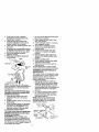
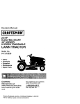
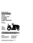
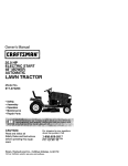
Owner's Manual
20.0 HP
ELECTRIC START
48" MOWER
AUTOMATIC
LAWN TRACTOR
Model No.
917.272244
•
•
•
•
Safety
Assembly
Operation
Maintenance
• Repair Parts
CAUTION:
Read and follow all
Safety Rules and Instructions
before operating this equipment.
For answers to your questions
about this product, Call:
1-800-659-5917
Sears Craftsman Help Line
5 am - 5 prn, Man - Sat
Sears, Roebuck and Co., Hoffman Estates, IL 60179
Visit our Craftsman website: www.sears.com/craftsman
Warranty ...............................................
Safety Rules .........................................
Product Specifications ..........................
Assembly ..............................................
Operation ............................................
Maintenance
Schedule ......................
Maintenance ....................................... 18
Service and Adjustments .................... 22
Storage ............................................... 29
Troubleshooting ................................. 30
Repair Pads ........................................ 34
Parts Ordering ..................... Back Cover
2
3
6
8
12
18
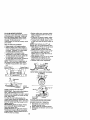
LIMITED TWO YEAR WARRANTY ON CRAFTSMAN RIDING EQUIPMENT PARTS
For two (2) years from the date of purchase, if this Craftsman Riding Equipment is
maintained, lubricated and tuned up according to the instructions in the owner's
manual, Sears wLIIrepair or replace, free of charge, any parts found to be defective in
material or workmanship. Warranty service is available free of charge by returning
your Craftsman riding equipment to your nearest Sears Service Center. In-home
warranty service is available but a tdp charge will apply. This warranty applies only
while this product is in the United States.
This Warranty does not cover:
• Expendable items which become worn during normal use, such as blades, spark
plugs, air cleaners, belts and oil filters.
• Tire replacement or repair caused by punctures from outside objects, such as nails,
thorns, stumps, or glass.
• Repairs necessary because of operator abuse, including but not limited to, damage
caused by towing objects beyond the capability of the riding equipment, impacting
objects that bend the frame or crankshaft, or over speeding the engine.
• Repairs necessary because of operator negligence, including but not limited to,
electrical and mechanical damage caused by improper storage, failure to use the
proper grade and amount of engine oil, failure to keep the deck clear of flammable
debris, or the failure to maintain the equipment according to the instructions
contained in the owner's manual.
• Engine (fuel system) cleaning or repairs caused by fuel determined to be contaminated or oxidized (stale). In general, fuel should be used within thirty (30) days of its
purchase date.
• Riding equipment used for commercial or rental purposes. A product is "used for
commercial purpose" if is used for any purpose other than single family household
dwellings or in usage where profit is made.
LIMITED 90 DAY WARRANTY ON BATrERY
For ninety (90) days from date of purchase, if any battery included with this riding
equipment proves defective in material or workmanship and our testing determines
the battery will not hold a charge, Sears will replace the battery at no charge. Warrarity service is available free of charge by returning your Craftsman riding equipment
to your nearest Sears Service Center. In-home warranty service is available but a trip
charge will apply. This warranty applies only while this product is in the United States.
TO LOCATE THE NEAREST SEARS SERVICE CENTER OR TO SCHEDULE INHOME WARRANTY SERVICE, SIMPLY CONTACT SEARS AT 1-800-4-MY-HOME
This Warranty gives you specific legal dghts, and you may also have other rights
which may vary from state to state.
Sears, Roebuck
and Co., D/817 WA, Hoffman
2
Estates,
FL 60179
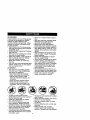
MPORTANT: This cuttng machine is capable of amputating hands and feet and
throwing objects. Failure to observe the following safety instructionscould result in
serious inju_ or death.
L GENERAL OPERATION
I1. SLOPE OPERATION
• Read, understand, and to[low all
Slopes are a major factor related to leas-ofinstructionsin the manual and on the
control and tipover accidents, which can result in severe injury or death. All slopes
machine before starting.
requireextra caution, Ifyou cannotback up
• Only allow responsibleadults, who are
the slope or if you feel uneasy on it, do not
familiar with the instructions,to operate
mow it.
the machine.
DO:
• Clear the area of objects such as rocks,
• Mow up and down slopes, not across.
toys, wire, etc., which couldbe picked
• Remove obstacles such as rocks,tree
up end thrown by the blade.
limbs,etc.
• Be sure the area is dear of other people
Watch for holes, ruts, or bumps. Uneven
before mowing. Stop machine if anyone
enters the area.
terrain could overturnthe machine. Tat/
grass can hide obstacles.
• Never carry passengers.
• Do nuf mow in reverse unless absolutely
Use slow speed. Choose a low gear so
necessary. Always look down and
that you will not have to stop or shift
behind before and while backing.
while on the slope.
Fo_lowthe manufacturer's recommenda• Be aware Ofthe mower discharge
directionand do not point it at anyone.
tions for wheel weights or counterDo not operate the mower withouteither
weights to improve stability.
the entire grass catcher or the guard in
Use extra care with grass catchers or
other attachments. These can change
place.
• Slow down before turning.
the stability of the machine.
Keep all movement on the slopes slow
• Never leave a running machine
unattended. Always turn off blades, set
and gradual. Do not make sudden
parking brake, stop engine, and remove
changes in speed or direction.
keys before dismounting.
Avoid starting or stopping on a slope. If
• Turn off bladeswhen not mowing.
tires lose traction, disengage the blades
• Stop engine before removing grass
and proceed slowly straight down the
catcher or uncloggingchute.
slope.
• Mow onlyin daylightor good artificial
DO NOT:
light.
• Do not turn on slopesunless necessary,
• Do not operate the machine while under
and then, turn slowly and gradually
the inf_ance of alcohel or drugs.
downhill, |f possible.
• Watch fortrafficwhen operating near or
• Do notmow near drop-effs, ditches,or
crossingroadways.
embankments. The mower could
• Use extra care when Ioadlm:Jor unloadsuddenly turn ever if a wheel is over the
ing the machine intoa trailer or truck.
edge of a cliffor ditch,or if an edge
• Data indicatesthat operators, age 60
caves in.
years and above, are involved in a large
• Do not mow on wet grass. Reduced
percentage of riding mower-ralated
tractioncould cause sliding.
injuries. These operators should
• DO not try to stabilizethe machine by
evaluate their ability to operate the riding
puttingyour foot on the ground.
mower safely enough to protect them• Do notuse grass catcher on steep
selves and others from serious injury.
slopes.
• Keep machine free of grass, leaves or
other debds build-up which can touch
hot exhaust / engine parts and bum. Do
not allow the mower deck to plow leaves
or other debris which can cause buildup to occur. Clean any oil or fuel
spillage before operating or storing the
machine. Allow m._chieeto cool before
storage.
3
IlL CHILDREN
Tragic accidents can occur if the operator
is not alert to the presence of children.
Children are often attracted to the
machine and the mowing activity. Never
assume that children will remain where
you last saw them.
• Keep children out of the mowing area
and under the watchful care of another
responsible adult.
• Be alert and turn machine off if children
enter the area.
• Before and when backing, look behind
and down for small children.
• Never carry children. They may fall oft
and be sedously injured or intedere
with safe machine operation.
• Never allow children to operate the
machine.
• Use extra care when approaching blind
comers, shrubs, trees, or other objects
that may obscure vision.
IV. SERVICE
• Use extra care in handling gasoline
and other fuels. They are flammable
and vapors are explosive.
-Use only an approved container.
-Never remove gas cap or add fuel
with the engine running. Allow
engine to COOlbefore refueling. 0o
not smoke.
-Never refuel the machine indoors.
-Never store the machine or fuel
container inside where there is an
open flame, such as a water heater.
• Be sure the area is clear of other
people before mowing. Stop machine if
anyone enters the area.
• Never carry passengers or children
even with the blades off.
• DO not mow in reverse unless absolutely necessary. Always look down
and behind before and while backing.
• Never carry children. 3"hey may lall off
and be seriously injured or interfere
with safe machine operation.
• Keep children out of the mowing area
and under the watchful care of another
responsible adult.
• Never run a machine inside a closed
area.
• Keep nuts and bolts, especially blade
attachment bolts,tight and keep
equipment in good condition.
• Never tamper with safety devices.
Check their proper operation regularly.
• Keep machine free of grass, leaves, or
other debds build-up. Clean oil or fuel
spillage. Allow machine to cool before
stodng.
• Stop and inspect the equipment if you
strike an object. Repair, if necessary,
before restarting.
• Never mare ad_Jstments or repairs
with the engine running.
• Grass catcher components are subject
to wear, damage, and deterioration,
which could expose moving parts or
allow objects to be thrown. Frequently
check components and replace with
manufacturer's recommended parts,
when necessary.
• Mower blades are sharp and can cut.
Wrap the blade s) or wear gloves, and
use extra caution when sew c ng them.
• Check brake operation frequently.
Adjust and service as required.
• Be alert and turn machine off if children
enter the area.
• Before and when backing, look behind
and down for small children.
• Mow up and down slopes (15° Max),
not across.
• Remove obstacles such as rocks,tree
limbs, etc.
• Watch for holes, ruts,or bumps.
Uneven terrain could overturn the
machine. Tall grass can hide obstacles.
4
• Use slow spend. Choose a low gear so
that you will not have to stop or shift
while on the slope.
• Avoid starting or stopping on a slope. If
tires lose traction, disengage the
blades and proceed slowly straight
down the slope.
• If machine stops while going uphill,
disengage blades, shift into reverse
and back down slowly.
• Do not turn on slopes unless necessary, and then, turn slowly and gradually downhill, if possible.
_)&Lock for this symbol to point out
important safety precautions. It means
CAUTION!J! BECOMEALERT!!! YOUR
SAFETY IS INVOLVED.
,_kCAUTION: In order to prevent
accidental startingwhen setting up,
transporting, adjusting or making repairs,
always disconnect spark plug wire and
place wire where it cannot contact spark
plug.
•(_CAUTION: Do not coast down a hill in
neutral, you may lose control of the
tractor.
_CAUTION;
Tow onlythe attachments
that are recommended by and comply
with specificationsof the manufacturer of
your tractor. Use common sense when
towing. Operate only at the lowest
possiblespeed when on a slope. Too
heavy of a load, while on a slope, is
dangerous. Tires can lose tractionwith
the ground and cause you to lose control
of yourtractor.
_WARNING:
Engine exhaust some of
its consttuants, and certain vehicle
components contain or emit chemicals
known to the State of California to cause
cancer and birth defects or other reproductive harm.
4_WARNING: Batter,!posts, terminals
and related accessones contain lead and
lead compounds, chemicals known to the
State of California to cause cancer and
birth defects or other reproductiveharm.
Wash hands after handling.
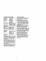
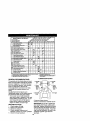
PRODUCT
SPECIFICATIONS
REPAIR AGREEMENT
GASOLINE
CAPACITY
AND TYPE:
OILTYPE
A Repair Agreement is available on this
product, Contact your nearest Sears
store for details,
(API-SF-SJ):
OIL CAPACITY:
3.5 GALLONS
UNLEADED
REGULAR
SAE 10W30
(ABOVE 32°F)
SAE 5W-30
(BELOW 32°1=)
W/FILTER: 4.5 PINTS
WiOFILTER:4.0 PINTS
CHAMPION RC12YC
CUSTOMER RESPONSIBILITIES
• Read and observe the safety rules.
• Fellow a regular schedule in maintaining, cadng for and using your tractor.
• Follow the instructionsunder "Maintenance" and "Storage" sections of this
owner's manual.
_WARNING:
This tractor is equipped
with an internal combustionengine and
should not be used on or near any
unimproved forest-covered, brushcovered or grass-covered land unless the
engine's exhaust system is equipped with
a spark arrester meeting applicable local
or state laws (if any). If a spark arraster is
used, it should be maintained in effective
working order by the operator.
In the state of California the above is
required by law (Section 4442 of the
California Public Resoumes Code).
Other states may have similar laws.
Federal laws apply on federal lands. A
spark arrester for the muffler is available
through your nearest Sears service
center (See REPAIR PARTS section of
this manual).
SPARK PLUG:
GAP: .030")
GROUND SPEED FORWARD: 0-5,5
(MPH):
REVERSE: 0-2.4
TIREPRESSURE: FRONT: 14 PSI
REAR: 10 PSI
CHARGING
SYSTEM:
15 AMPS @ 3600 RPM
BATTERY:
AMP/HR:
30
MIN. CCA: 240
CASE SIZE: U 1R
BLADE BOLT
45-55 FT, LBS.
TORQUE:
CONGRATULATIONS on your purchase
of a new tractor. It has been designed,
engineered and manufactured to give you
the best possible dependability and
performance.
Should you experience any problem you
cannot easily remedy, please contact a
Sears or other qualified service center.
We have competent, well-trained technicians and the proper tools to service or
repair this tractor.
Please read and retain this manual. The
instructionswill enable you to assemble
and maintain your tractor properly.
Always observe the "SAFETY RULES",
6
Steering Wheel
Steering
Wheel insert
Steedng Sleeve
(1) W_
17/32 x 1-,3/16 x 12 Gauge
i_(1)
(5) Retainer Springs
Mower
Knob
(2)Flanged
(1)FrontPlate
_"
(2) Retainer Springs (single loop)
Assemb,y
_r" (4) Adjusting Bar
_
Gauge Wheels
_
_--_
|
(4) RetainerSpdngs
(4,L_clevisPins_j
(doub,e,oop)
3/8-16
_,_4>
Wheels
<4, Washers L_..._J
3/8 x 3/4 x 14 Ga?_=.f
[_" (4) Shoulder Bolt
Nose Roller_
--
Nose Rolle_
(2) Locknuts
5/16-18
Video Cassette
_/r
Nose Roller
(2) Hex Bolts
S .
5/1_-1_x 1
Keys
_"_/(2)
_
W ashe rs _=._._'
17/32 x 7/8 x 16 Ga.--
Slope Sheet
(2) Keys
For FutureUse
7
Your new tractor has been assembled at the factory with exception of those parts left
unassembled for shipping purposes. To ensure safe and proper operation of your
tractor all parts and hardware you assemble must be tightened securely. Use the
correct tools as necessary to insure proper tightness. Review the video cassette before
you begin.
TOOLS REQUIRED
FOR ASSEMBLY
A socket wrench set will make assembly
easier. Standard wrench sizes you need
are listed below.
(2) 9/16" wrench
(1) 3/4" Socket w/
(1) 1/2" wrench
drive ratchet
(1) Utility knife
(1) Pliers
(1) "nre pressure gauge
I( )1
When dght or left hand is mentioned in
this manual, it means, from your point of
view, when you are in the operating
position (seated behind the steering
wheel).
TO REMOVE TRACTOR FROM
CARTON
UNPACK CARTON
1. Remove all accessible loose parts
and parts cartons from carton.
2. Cut, from top to bottom, along lines on
all four corners of carton, and lay
panels flat.
3. Remove mower and packing matedals.
4. Check for any additional loose parts
or cartons and remove.
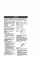
BEFORE REMOVING TRACTOR
FROM SKID
ATTACH STEERING WHEEL
1. Remove Iocknut and large flat washer
from steering shaft.
2. Position front wheels of the tractor so
they ere pointing straight forward.
3. Slide the steedng sleeve over the
steering shaft.
4. Position steedng wheel so cross bars
are horizontal (left to right) and slide
onto steering wheel adapter.
5. Secure steering wheel te steedng
shaft with Iocknut and large flat
washer previously removed. Tighten
securely.
6. Snap steering wheel insert into center
of steering wheel.
7. Remove protective materials from
tractor hood and grill.
IMPORTANT; Check for and remove any
staples in skid that may puncture tires
where tractor is to roll off skid.
SteeringWheel
Adapter _
Look Nut
I_
I_ge
Steering
Flat Washer
___
Shaft
Steering
t,
_._,
]_
_,_
,
¥
-.-I
u
.
,?,
_
,,
iii
,,,
)
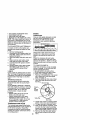
HOW TO SET UP YOUR TRACTOR
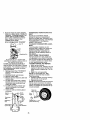
CHECK BATTERY
1. Lift hood to raised position.
NOTE: if this battery is put into service
after month and year indicated on label
(label located between terminals) charge
battery for minimumof one hour at 6-10
amps. (See "BATTERY" in Maintenance
section of this manual for charging
instructions). .....
/ Label
INSTALL
SEAT
Adjust seat before tightening adjustment
knob.
1, Remove adjustment knob and fiat
washer securing seat to cardboard
packing and set aside for assembly of
seat to tractor.
2. Pivot seat upward and remove from
the cardboard packing. Remove the
cardboard packing and discard,
3. Place seat on seat pan so head of
shoulder bolt is positioned over large
8
slotted
hole in pan.
4. Push down on seat to engage
shoulder bolt in slot and pull seat
towards rear of tractor.
5. Pivot seat and pan forward and
assemble adjustment knob and flat
washer loosely. Do not tighten.
6. Lower seat into operating position and
sit in seat.
7. Slide seat until a comfortable position
is reached which allows you to press
clutch/brake pedal all the way down.
8. Get off seat without moving its
adjusted position.
9. Raise seat and tighten adjustment
knob securely.
NOTE: You may now roll or drive your
tractor off the skid. Follow the appropriate
instruction bek_w to remove the tractor
from the skid.
TO ROLLTRACTOR
OFF SKID (See
Operation section for location and
function of controls)
t. Press lift lever plunger and raise
attachment lift lever to itshighest
position.
2. Release parking brake by depressing
brake pedal.
3. Place freewheel control in freewheeling position to disengage transmission (See "TO TRANSPORT' in the
Operation section of this manual),
4. Roll tractor forward off skid,
TO DRIVE TRACTOR OFF SKID (See
Operation section for location and
function of controls)
_1_WARNING: Before starting, read,
understand and follow all instructionsIn
the Operation section of this manual. Be
sure tractor is in a well-ventilated area. Be
sure the area in front of tractor Is clear of
other people and objects.
1. Be sure all the above assembly steps
have been completed.
2. Check Brig(he oil level and fill fuel
tank with gasoline.
3. Place freewheel control in "transmission engaged" position.
4. Sit on seat in operating position,
depress brake pedal and set the
parking brake.
5, Press lift lever plunger and raise
attachment lift lever to its highest
position.
6. Start the engine. After engine has
started, move throttle control to idle
position.
7. Release parking brake.
8. Slowly depress forward ddve pedal
and ddve tractor off skid.
9. Apply brake to stop tractor and set
parking brake.
"t0.Turn ignition key to "OFF" position.
Continue with the instructions that follow.
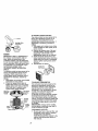
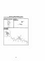
ASSEMBLE GAUGE WHEELS TO
MOWER DECK
The gauge wheels are designed to keep
the mower deck in proper position when
operating mower. Be sure they are
properly adjusted to ensure optimum
mower peliornqance.
1. Slide gauge wheel bar down into
bracket channel, Be sure that gauge
wheel bar aligning holes are on top,
Assemble gauge wheels as shown
using shoulder bolts, 3/8 washers and
3/8-16 center Iocknuts and tighten
securely.
2. For ease of mower to tractor assembly, raise gauge wheels to highest
position and retain with clevis pins
and spring retainers.
NOTE: Adjust gauge wheels before
operating mower. See "TO ADJUST
GAUGE WHEELS" in the Operation
section of this manual.
Pin
Shoulder
Boil
Adjusting
Bar
Gauge
Wheel
_Locknut
3/8-16
Center
6. Install belt into electdc clutch pulley
groove.
7. Place the suspension arms on
outward pointing deck pins. Retain
with double loop retainer spring with
loops up as shown.
8. Install front plate assembly 1otractor
suspension brackets and retain with
single loop retainer springs as shown.
9. Position front plate assemb]y between
front mower brackets. Raise deck and
Tab
Nose Roller
plate assembly to align holes and
Lock
insert flanged pins. Secure pins with
•B" Bracket
double loop retainer springs between
the plate assembly and mower
brackets.
NOTE: To assist in locatinghole in
Hex Bolt
flanged pin, the hole in pin is inline with
notch on head of pin. If necessary, move
mower side-to-side to give space
between plate and mower brackets.
Bracket
IMPORTANT: Check belt for proper
INSTALL MOWER AND DRIVE BELT
routing in all mower pulley grooves.
Be suretractoris on levelsurfaceand mower
10.Engage belt tension rod by pushing
suspensionarms are raisedwi_ attachment
rod into locking bracket.
•qLCAUTION: Belt tension rod is spring
liftcontrol.Engage parking brake.
loaded. Have a tight grip on red and
1. Cut and remove ties securing antisway bar and belts. Swing anti-sway
engage slowly.
bar to left side of mower deck.
11 .Connect anti-sway bar to chassis
bracket under left footrest and retain
2. Slide mower under tractor with
with double loop retainer spring.
deflector shield to dght side of tractor.
12.1f equipped, turn height adjustment
IMPORTANT: Check belt for proper
knob clockwise to remove slack from
routing in aUmower pulley grooves.
mower suspension.
3. If equipped, turn height adjustment
13. Raise deck to highest position.
knob counterclockwise until it stops.
14.Adjust gauge wheels before operating
4. Lower mower linkage with attachment
lift control.
mower as shown in the Operation
section of this manual.
5. Be sure belt tension rod is in disen-
TO ATrACH
NOSE
ROLLER
1. Position brackets, 17/32 x 7/8 x 16
gauge washers, and nose roller
between deck mounting brackets as
shown. Be sure to position brackets
on correct side, as shown.
2. Install hex bolts and lock nuts as
shown. Tighten hardware securely.
NOTE: Be sure bracket tabs are positioned in tab holes in deck brackets.
gaged position.
Lock
Belt Tension Rod
Disengaged Position .-_,'J
Chassis
Electric Clutch
Pulley
Front
Mower
Bracket
Front Suspension Brackets
Front Plate Assembly
_Double Loop
Retainer Springs
Gauge
Wheel
Single
Loop
Retainer
Springs
Double Loop
Retainer Spring
Anti-Sway
USEPUERSFOR I
RETAINERSPRINGSI
/_Loop
Up
Spring (Outward
Suspension
Double LoopArms
Retainer
pointing deck pins)
Shield
10
CHECK TIRE PRESSURE
The tires on your tractor were overinflated
at the factory for shippingpurposes.
Correct tire pressure is impodant for best
cutting performance.
• Reduce tire pressure to PSi shown in
"PRODUCT SPECIFICATIONS" section
of this manual.
CHECK DECK LEVELNESS
For best cutting results, mower housing
should be properly leve]ed. See "TO
LEVEL MOWER HOUSING" in the
Service and Adjustments section of this
manual.
CHECK FOR PROPER
ALL BELTS
POSITION
OF
See the figures that are shown for
replacing motion and mower blade drive
belts in the Service and Adjustments
section of this manual. Verify that the
belts are muted correctly.
CHECK BRAKE SYSTEM
After you learn how to operate your
tractor, check to see that the brake is
propedy adjusted, See "TO ADJUST
BRAKE" in the Service and Adjustments
section of this manual.
_CHECKLIST
BEFORE YOU OPERATE AND ENJOY
YOUR NEW TRACTOR, WE WISH TO
ASSURE THAT YOU RECEIVETHE BEST
PERFORMANCE AND SATISFACTION
FROM THIS QUALITY PRODUCT.
PLEASE REVIEWTHE FOLLOWING
CHECKLIST:
/ All assembly instructionshave been
completed.
#' No remaining loose parts in carton.
/ Battery is propedy prepared and
charged. (Minimum 1 hour at 6 amps).
#" Seat is adjusted comfortably and
tightened securely.
#"All tires are properly inflated. (For
shipping purposes, the tires were
overinflated at the factory).
J Be sure mower deck is properly leveled
side-to-side/front-to-raar for best cutting
results. (Tires must be properly inflated
for leveling).
/ Check mower and drive belts. Be sure
they are routed propedy around puneys
and inside all belt keepers.
#" Check wiring. See that all connections
are still secure and wires are propedy
clamped.
/ Before driving tractor, be sure freewheel control is in drive position.
WHILE LEARNING HOW TO USE YOU R
TRACTOR, PAY EXTRA ATTENTION TO
THE FOLLOWING IMPORTANT ITEMS:
•/ Engine oil is at proper level.
J' Fuel tank is filled with fresh, clean,
regular unleaded gasoline.
#" Become familiar with all controls - their
location and function. Operate them
before you start the engine.
,/Be sure brake system is in safe
operating condition.
,/It is impodant to purge the transmission
before operating your tractor for the first
time. Follow proper starting and
transmission purging instructions (See
"TO START ENGINE" and "PURGE
TRANSMISSION" in the Operation
section of this manual).
11
These symbols may appear on your tractor or in literature supplied with the product.
Learn and understand their meaning.
SATFERY
ENGINE ON
CAUTION OR
WARNING
ENGINE OFF
REVERSE
FORWARD
OfL PRESSURE
FAST
SLOW
LIGHTS ON
OVERuGFITTSMP
I
M
FUEL
CHOKE
ATFACHMENT
GLUTCH ENGAGED
IGNITION
REVERSE
MOWER
NEUTRAL
ATTACHMENT
CLUTCH DISENGAGED
HEIGHT
PARKING BRAKE
LOOKED
H
L
HIGH
LOW
KEEP AREA CLEAR
UNLOCKED
MOWER
®3I
PARKING
BRAKE
SLOPE HAZARDS
(SEE SAFET_ RULES SECTION)
FREE WHEEL
DANGER,
KEEP HANDS
AND FEET
AWAY
(Automatic
12
LIFT
ModeLs only)
KNOWYOURTRACTOR
READ THIS OWNER'S MANUAL AND SAFETY RULES BEFORE OPERATING
YOUR TRACTOR
Compare the illustrations with your tractor to familiarize yourself with the locations of
various controls and adjustments. Save this manual for future reference,
Hourmeter
Ignition
Light Switch Position
Attachment Clutch Switch
Ammeter
Attachment Lift Lever
,Reverse Drive Pedal
• _ ....
Adjustment
indicator
_"
Brake
Freewheel
Cruise Control Lever
Our tractorsconform to the safety standards of the
American National Standards Institute.
ATTACHMENT CLUTCH SWITCH: Used
to engage the mower blades, or other
attachments mounted to your tractor.
LIGHT SWITCH'. Turns the headlights on
and off.
THRO'I'FLE CONTROL - Used to control
engine speed.
CHOKE CONTROL - Used when starting
a cold engine.
BRAKE PEDAL: Used for braking the
tractor and starting the engine.
FREEWHEEL CONTROL: Disengages
transmissionfor pushing or slowly towing
the tractorwith the engine off.
ATTACHMENT LIFT LEVER: Used to
raise, lower and adjust the mower deck
or other attachments mounted to your
tractor.
LIFT LEVER PLUNGER: Used to release
attachment lift lever when changing its
position.
IGNITION SWITCH: Used for starting and
stopping the engine,
AMMETER= Indicates battery charging (+)
or discharging (-).
PARKING BRAKE: Locks clutch/brake
into the brake position.
FORWARD DRIVE PEDAL - Used for
forward movement of tractor.
REVERSE DRIVE PEDAL - Used for
reverse movement of tractor.
CRUISE CONTROL LEVER - Used to set
forward movement of tractor at desired
speed without holding the forward drive
pedal.
HOURMETER - Indicates hours of
operation.
13
The operation of any tractor can result in foreign objects thrown into the
I
eyes, which can result in severe eye damage. Always wear safety glasses
or eye shields while operating your tractor or performing any adjustments
or repairs. We recommend a wide vision safety mask over spectacles, or
standard safety glasses.
IMPORTANT: Leaving the ignition switch
in any position other than =OFF• will
cause the battery to be discharged,
(dead).
NOTE: Under certain conditions when
tractor is standing idle with the engine
running, hot engine exhaust gases may
cause'browning" of grass. To eliminate
this possibility, always stop engine when
stopping tractor on grass areas.
_CAUTION:
Always stop tractor
completely, as described above, before
leaving the operator's position; to empty
grass catcher, etc.
THROTTLE CONTROL
Always operate engine at full throttle.
• Operating engine at less than full
throttle reduces the battery charging
rate.
• Full throttleoffers the best bagging and
mower performance.
TO USE CHOKE CONTROL
Use choke control whenever you are
Throttle
starting a cold engine. Do not use to start
a warm engine.
"Brake'_
_
• To engage choke control, pull knob out.
Positio
ReV_rri_,e Slowly push knob in to disengage.
TO MOVE FORWARD AND
BACKWARD
The
direction and speed of movement is
B,ake p_,n_raK,
kruise
"Drive" "Disengaged" Engflged
Control controlled by the forward and reverse
Position Position
Pos_tmon
Leve_
drive pedals.
1. Start tractor and release parking
STOPPING
brake.
MOWER BLADES 2. Slowly depress forward or reverse
• To stop mower blades,move attachddve pedal to begin movement.
ment clutchswitch to "DISENGAGED"
Ground speed increases the further
osition.
down the pedal is depressed.
GRPouND DRIVE TO USE CRUISE CONTROL
• To stop ground drive, depress brake
The cruise control feature can be used for
pedal into full "BRAKE" position.
forward travel only.
IMPORTANT; Forward and reverse dhve
1. With forward dnve pedal depressed to
_edals return to neutral position when not
desired speed, move cruise control
epressed.
lever forward to SET" position and
ENGINE hold while lifting your foot off the
• Move throttle control to slow position.
pedal, then release the cruise control
NOTE: Failure to move throttle control to
lever.
slow position and allowing engine to idle
To disengage the cruise control, pull the
before stopping may cause engine to
lever backward to OFF" position, or fully
"backfire,".
depress the brake pedal.
• Turn ignition key to "OFF" position and
TO ADJUST MOWER CUTTING HEIGHT
remove key. Always remove key when
The position of the attachment lift lever
leaving tractor to prevent unauthorized
determines the cutting height,
use.
• Grasp lift lever.
• Never use choke to stop engine.
• Press plunger with thumb and move
14 lever to desired position.
HOW TO USE YOUR TRACTOR
TO SET PARKING BRAKE
Your tractor is equipped with an operator
_resence sensing switch. When engine
running, any attempt by the operator to
leave the seat without first setting the
Parking brake will shut off the engine•
• Depress brake pedal into full"BRAKE"
position and hold.
2. Place parking brake lever in "ENGAGED" position and release
pressure from brake pedal. Pedal
should remain in "BRAKE" position.
Make sure parking brake will hold
tractor secure.
AttachmentClutch
Push-Into
Switch Pull Out To
"Disengaged" "En ge"
Forward_
Choke
Ddve Pedal
_
)
The cutting height range is approximately 1-112to 4". The heights are
measured from the ground to the blade
tip with the engine not running. These
heights are approximate and may vary
depending upon soil conditions, height of
grass
typeslawn
of grass
being
mowed.
The and
average
should
be cut
to
approximately 2-1/2 inches during the
cool season and to over 3 inches
during hot months. For healthier and
better looking lawns, mow often and
after moderate growth.
• For best cutting performance, grass
over 6 inches in height should be
mowed twice. Make the first cut
relatively high; the second to desired
height.
TO ADJUST GAUGE WHEELS
Gauge wheels are properly adjusted
when they are slightly off the ground
when mower is at the desired cutting
height in operating position.Gauge
wheels then keep the deck in pro.per
positionto help prevent scalping in most
terrain conditions.
NOTE: Be sure tractor is on a flat level
surface.
1. Lower mower and adjust mower to
desired cutting height.
2. Remove retainer spdng and clevis pin
which secure each gauge whee_ bar.
3. Lower gauge wheels to ground. Raise
bgaugewheels slightJy to align holes in
racket and gauge wheel bar and
insert clevis pin. Gauge wheels
should be slightly off the ground.
4. Replace retainer spring into clevis pin.
5. Be sure all gauge wheels are in the
same setting.
IMPORTANT: Be sure to readjust gauge
wheels if you change the cutting height
of the mower deck.
Retainer
TO OPERATE MOWER
Your tractor is equipped with an operator
presence sensingswitch. Any attempt by
the operator to leave the seat with the
engine running and the attachment clutch
engaged will shut off the engine.
1. Select desired height of cut.
2. Start mower blades by engaging
attachmeet clutch control.
TO STOP MOWER BLADES disengage attachment clutch control.
ACAUTION:
Do not operate the mower
without either the entire grass catcher, on
mowers so equipped, or the deflector
shield in place.
Attachment Clutch
Attachment Lift
SwitchPull Out To
Lever High Position
"Eng_
Position
_" -- Low
- -\
Dellector
TO OPERATE ON HILLS
,i_CAUTION: Do not drive up or down
hills with slopes greater than 15° and do
net drive acress any slope.
• Choose the slowest speed before
starting up or down hills.
• Avoid stopping or changing speed on
hilJs.
• If stopping is absolutely necessary,
push brake pedal quickly to brake
position and engage parking brake.
• To restart movement, slowly release
parking brake and brake pedal.
• S_owlydepress appropriate drive pedal
to slowest setting.
• Make all turns slowly.
TO TRANSPORT
When pushing or towing your tractor, be
sure to disengage transmission by
placing freewheel control in freewheeling
position. Free wheel control is located at
the rear drawbar of tractor.
1. Raise attachment lift to highest
position with attachment lift control.
2. Pull freewheel control out and into the
slot and release so it is held in the
disengaged pos{tion.
• Do not push or tow tractor at more than
two (2) MPH.
• To re-engage transmission, reverse
above procedure.
NOTE: To protect hood from damage
when transporting your tractor on a truck
or a trailer, be sure hood is closed and
secured to tractor, Use an appropriate
means of tying hood to tractor (rope, cord,
etc.).
15
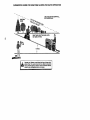
TOWING CARTS AND OTHER AI-rACHMENTS
Tow only the attachments that are
recommended by and comply with
specificationsof the manufacturer of your
tractor. Use common sense when towing.
Too heavy of a load, while on a slope, is
dangerous. _res can lose traction with
the ground and cause you to lose control
of yourtractor.
BEFORE STARTING THE ENGINE
CHECK ENGINE OIL LEVEL
The engine in your tractor has been
shipped, from the factory, already filled
with summer weight oil.
1. Check engine oil with tractor on level
ground.
2. Unthread and remove oil fill cap/
dipstick; wipe oil off. Rcinsert the
dipstick into the tube and rest oil fill
cap on the tube. Do not thread the
cap onto the tube. Remove and read
oil level. If necessary, add oil until
"FULL" mark on dipstickis reached.
Do not overfill.
• For cold weather operation you should
change oilfor easier starting(See "OIL
VISCOSITY CHART" in the Maintenance section of this manual).
• To change engine oil, see the Maintenance section in this manual.
ADD GASOUNE
• Fill fuel tank. Use fresh, clean, regular
unleaded gasoline with a minimum of
87 octane. (Use of leaded gasoline will
increase carbon and lead oxide
deposits and reduce valve life), Do not
mix oil with gasoline. Purchase fuel in
quantities that can be used within 30
days to assure fuel freshness.
IMPORTANT: When operating in temperatures below 32°F(0°C), use fresh,
clean winter grade gasoline to help
insure good cold weather starting.
_WARNING: Experience indicates that
alcohol blended fuels (called gasohol or
using ethanol or methanol) can attract
moisture which leads to separation and
formation of acids dudng storage. Acidic
gas can damage the fuel system of an
engine while in storage. To avoid engine
problems, the fuel system should be
emptied before storage of 30 days or
longer. Drain the gas tank, startthe
engine and let it run until the fuel lines
and carburetor are empty. Use fresh fuel
next season. See Storage Instructionsfor
additional information. Never use engine
or carburetor cleaner products in the fuel
tank or permanent damage may occur.
_-CAUTION: Fillto bottom of gas tank
filler neck. Do not overfill. Wipe offany
spil]ed oil or fuel. Do not store, spill or use
gasoline near an open flame.
TO START ENGINE
When starfing the engine for the first time
or if the engine has run out of fuel, it will
take extra crankingtime to move fuel from
the tank to the engine.
1. Be sure freewheel control is in the
transmission engaged position.
2. Sit on seat in operating position,
depress brake pedal and set parking
brake.
3. Move attachment clutch to "DISENGAGED" position.
4. Move throttle control to fast position
5. Pull choke control out for a cold
engine start attempt. For a warm
engine start attempt the choke control
may not be needed.
NOTE; Before starting, read the warm and
cold starting procedures below.
6. Insert key into ignitionand turn key
clockwise to "STAR'r" position and
release key as soon as engine starts.
Do not run starter continuouslyfor
more than fifteen seconds per minute.
If the engine does not start after
several attempts, push choke control
in, wait a few minutes and try again. If
engine still does not start, pull the
choke control out and retry.
WARM WEATHER STARTING (50° F and
above)
7. When engine starts, slowly push
choke control in until the engine
begins to run smocthly. If the engine
starts to run roughly, putt the choke
control out slightly for a few seconds
and then continua to push the control
in slowly.
• The attachments and ground drive can
now be used. If the engine does not
accept the load, restart the engine and
allow it to warm up for one minute
using the choke as described above.
COLD WEATHER STARTING (50 ° F and
below)
7. When engine starts, slowly push
choke contret in until the engine
begins to run smoothly. Continue to
push the choke control in small steps
allowing the engine to accept small
changes in speed and toad, until the
choke control is fully in. If the engine
starts to run roughly, pullthe choke
control out slightlyfor a few seconds
and then continue to push the control
in slowly. This may require an engine
warm-up pedod from several seconds
to several minutes, depending on the
16
temperature.
6. Engage transmission by placing
AUTO MATiC TRANS MISSION WARM UP
freewheel control in driving position
Before driving the unit in cold weather,
See =TOTRANSPORT" in this section
the transmissionshould be warmed up as
of manua ).
follows:
7. Sitting in the tractor seat, start engine.
f. Be sure the tractor is on level ground.
After the engine is running, move
2. Release the parking brake and let the
throttle control to half (1/2) speed.
brake slowly return to operating
Disengage parking brake.
position.
8. Drive tractor forward for approximately
3. Allow one minute for transmissionto
five feet then backwards for five feet.
warm up. This can be done during the
Repeat this driving procedure three
engine warm up period.
times.
• The attachments can be used during
Your tractor is now purged and now ready
the engine warm-up period after the
for normal operation.
transmtssionhas been warmed up and
may require the choke control be
MOWING TIPS
pulled out slightly.
• Mower should be properly leveled for
NOTE: If at a high altitude (above 3000
best mowing performance. See "3"0
LEVEL MOWER HOUSING" in the
feet) or in cold temperatures (below 32 F)
the carburetor fuel mixture may need to
Service and Adjustments section of this
be ad usted for best engine performance.
manual.
See "TO ADJUST CARBURETOR" n the
• The ]eft hand side of mower should be
Service and Adjustments section of this
used for trimming.
manual.
• Drive so that clippings are discharged
PURGE TRANSMISSION
onto the area that has been cut. Have
_CAUTION:
Never engage or disengage
the cut area to the right of the tractor.
This will result in a more even distribufreewheel lever while the engine is
tion of clippings and more uniform
running.
To ensure properoperation and perforcutting.
mance, it is recommendedthat the
• When mowing large areas, start by
transmissionbe purged before operating
turning to the right so that clippings will
tractorfor the first time. This procedure will
discharge away from shrubs, fences,
removeany trapped air inside the transdriveways, etc. After one or two
missionwhich may have developed during
rounds, mow in the opposite direction
shipping of yourtractor.
making left hand turns until finished.
IMPORTANT: Should your transmission
• If grass is extremely tall, it should be
mowed twice to reduce load and
require removal for sen'ice or replacement,
it shouldbe purged after ralnstallation
possible fire hazard from dried clipbefore operatingthe tractor.
pings. Make first cut relatively high; the
1. Place tractor safely on level surface
second to the desired height.
• Do not mow grass when it is wet. Wet
with engine off and parking brake set.
2. Disengage transmission by placing
grass will plug mower and leave
undesirable clumps. Allow grass to dry
freewheel control in freewheelin,g
position (See "TO TRANSPORT' in
before mowing.
this section of manual).
• Always operate engine at full throttle
3. Sitting in the tractor seat, start engine.
when mowing to assure better mowing
After the engine is running, move
performance and proper discharge of
throttle control to slow position.
material. Regulate ground speed by
Disengage parking brake.
selecting a low enough gear to give the
4. Depress forward drive pedal to full
mower cutting performance as well as
forward position and hold for five (5)
the quality of cut desired.
seconds and release pedal. Depress
• When operating attachments, select a
reverse drive pedal to full reverse
ground speed that will suit the terrain
position and hold for five (5) seconds
and give best performance of the
and release pedal. Repeat this
attachment being used.
procedure three (3) times.
f
NOTE= Duringthis procedure there will be
no movement of drive wheels. The air is
being removed from hydraulic drive
system.
5. Shut- off engine and set parking
brake.
17
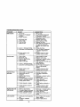
MAINTENANCE SCHEDULE
FILL IN DATES
AS YOU COMPLETE
REGULAR SERVICE
ERVICE
Check Brake Oper alion
check'n_
Pr=sure
Check Operator Presence and
I,/
_,te,k_Sy=,_,,
l,/
Check fo_-Loose F_t enels
_
ShatpeNReptace
DATES
_
I/
_
Mower Blades
_'
Vt,
Check Batlery Lever
Cle_'_ Battery and Terminals
If
Check Tra_axle
_
CCoting
I
Adjusl Blade Belt[s) T_sion
I ik_/s
Adjusl Molion Drive BeitIs) Tenslon
Check E_jirw Oil L_E4
_l_s
_
I_ /
Ch,_nge Engine Oil
_,_
Clean Air Filter
V'_
Cleai'_
_#_2
Air Scre_
InspectMuffledSpatkArrester
RepUte
V#
_1
Oil Fille f (If equipped}
1
I_lz
Clean F_glne Coo/ing Fins
_=
Replays Spalk plug
i# /
Replace Air FiRm"Paper cartdd_
_'_
I
!
Replace FL_I FiJter
6 - Not r_OL_ed I_ _ip_=d
_i_ maJ_t_at_fr _ b_
?. T_gh_n ffo_ _le p_=d b=t t_ 35114t_ rna_irn_n
3. If equipped wlt_ o_ filler, charge o_ _,,#_ry50 ho_s
LUBRICATION
GENERAL RECOMMENDATIONS
The warrantyon thistractor does not cover
items that have been subjected to operator
abuse or negligence. To recek'e full value
from the warranty, operator must maintain
tractor as instructed in this manual.
Some adjustments will need to be made
periodicallyto properly maintain your
tractor.
All adjustments in _e Service and
Adjustments section of this manuai should
be checked at least once each season.
• Once a year you should replace the
spark plug, clean or replace air _ter, and
check blades and belts for wear. A new
spark plug and clean air filter assure
proper air-fuel mixture and help your
engine run better and last longer.
BEFORE EACH USE
1. Check engine oil level.
2. Check brake operation.
3. Check tire pressure.
4. Check operator presence and
interlocksystems for proper operation.
5. Check for loose fasteners.
Spindle
Zsrk
CHART
Zerk
Fronl
Wheel
Bearing
Zerk
Wheel
Bearing
Zerk
Zerks i
=
General Purpose Grease
Refer to Mainlenance "ENGINE" Section
IMPORTANT: Do not oil or grease the
pivot points which have special nylon
bear-ings. Viscous lubricantswill attract
dust and dirt that will shorten the life of
the self°lubricatingbearings. If you feel
they must be lubricated, use only a dry,
powdered graphite type lubricant
sparingly.
18
TRACTOR
Always observe safety rules when
performing any maintenance.
BRAKE OPERATION
If tractor requires more than six (6) feet
stopping distance at high speed in
highest gear, then brake must be adjusted. (See "TO ADJUST BRAKE" in the
Service and Adjustments section of this
manual).
TIRES
• Maintain proper air pressure in all tires
(See =PRODUCT SPECIFICATIONS"
section of this manual).
• Keep tires free of gasoline, oil, or insect
control chemicals which can harm
rubber.
• Avoid stumps, stones, deep ruts, sharp
objects and other hazards that may
cause tire damage.
NOTE: To seal tire punctures and prevent
flat tires due to slow leaks, tire sealant
may be purchased from your local parts
dealer. Tire sealant also preventstire dry
rot and
corrosion.
OPERATOR PRESENCE SYSTEM
Be sure that operator presence and
interlocksystems are working propedy. If
your tractor does not function as described below, repair the problem
immediately.
• The engine should not start unless the
brake pedal is fully depressed and
attachment clutchcontrol is in the
disengaged position.
• When the engine is running, any
attempt by the operator to leave the
seat without first setting the parking
brake should shut off the engine.
• When the engine is running and the
attachment clutch is engaged, any
attempt by the operator to leave the
seat should shut off the engine.
• The attachment clutch should never
operate unless the operator is in the
seat.
BLADE CARE
For best results mower blades must be
kept sharp. Replace bent or damaged
blades.
BLADE REMOVAL
1. Raise mower to highest position to
allow access to blades.
2. Remove blade bolt.
3. Install new or resharpened blade with
trailing edge up towards deck as
shown.
iMPORTANT: To ensure proper assembly,
center hole in blade must align with star
on mandrel assembly.
4. Reassemble blade bolt tighten bolt
securely (45-55 Ft. Lbs. torque).
IMPORTANT: Blade bolt is grade 8 heat
treated.
Mandrel
Assembly
Trailing
/
TO SHARPEN BLADE
NOTE: We do net recommend sharpening blade - but if you do, be sure the
blade is balanced.
Care should be taken to keep the blade
balanced. An unbalanced blade will
cause excessive vibration and eventual
damage to mower and engine.
• The blade can be sharpened with a tile
or on a grinding wheel. Do not attempt
to sharpen while on the mower.
• To check blade balance, you will need
a 5/8 • diameter steel bolt, pin, or a cone
balancer. (When using a cone balancer, follow the instructions supplied
with balancer.)
NOTE: Do not use a nail for balancing
blade. The lobes of the center hole may
appear to be centered, but are not.
• Slide blade on to an unthreaded
portion of the steel bolt or pin and hold
the bolt or pin parallel with the ground.
If blade is balanced, it should remain in
a horizontal position. If either end of
the blade moves downward, sharpen
the heavy end until the blade is
balanced.
c o/j
or Pin -_._
BATTERY
Your tractor has a battery charging system
which is sufficientfor normal use. However, periodic charging of the battery with
an automotive charger will extend its life.
19
• Keep battery and terminals clean.
• Keep battery bolts tight.
• Keep small vent holes open.
• Recharge at 6-10 amperes for 1 hour.
NOTE: The original equipment battery on
your tractor is maintenance free. Do not
attempt to open or remove caps or Covers.
Adding or checking level of electrolyte is
not necessary.
TO CLEAN BA'I-FERY AND TERMINALS
Corrosion and dirt on the battery and
terminals can cause the battery to "leak"
power.
1. Remove terminal guard.
2. Disconnect BLACK battery cable first
then RED battery cable and remove
battery from tractor.
3. Rinse the battery with plain water and
dry.
4. Clean terminals and battery cable
ends with wire brush until bright.
5. Coat terminals with grease or petroleum jelly.
6. Reinstall battery (See "REPLACING
BATTERY" in the SERVICE AND
ADJUSTMENTS section of this
manual).
V-BELTS
Check V-belts for deterioration and wear
after 100 hours of operation and replace
if necessary. The belts are not adjustable.
Replace belts if they begin to slip from
wear.
TRANSAXLE COOLING
The transmission fan and cooling fins
should be kept clean to assure proper
cooling.
Do not attempt to clean fan or transmission while engine is running or while the
transmission is hot. To prevent possible
damage to seals, do not use high
pressure water or steam to clean
transaxle.
• Inspect coolingfan to be sure fan
blades are intact and clean.
• Inspect cooling fins for dirt, grass
clippings and other materials. To
prevent damage to seals, do not use
compressed air or high pressure
sprayer to clean cooling fins.
TRANSAXLE PUMP FLUID
The transaxle was sealed at the factory
and fluid maintenance is not required for
the life ofthe transaxle. Should the
transaxle ever leak or require servicing,
contact your nearest authorized service
center/department.
ENGINE
LUBRICATION
Only use high quality detergent oil rated
with API service classificationSF-SJ.
Select the oil's SAE viscositygrade
according to your expected operating
temperature.
SAE VISCOSITYGRADES
Change the oil after every 50 hours of
operation or at least once a year if the
tractor is not used for 50 hours in one
year.
Check the crankcase oil level before
startingthe engine and after each eight
(8) hoursof operation. Tighten oil fill cap/
dipsticksecurely each time you check the
oil level.
TO CHANGE ENGINE OIL
Determine temperature range expected
before oil change. All oil must meet API
service classification SF-SJ.
• Be sure tractor is on level surface.
• Oil will drain more freely when warm.
• Catch oil in a suitable container.
1. Remove oil fill cap/dipstick. Be careful
not to allow dirt to enter the engine
when changing oil.
2. Remove yellow cap from end of drain
valve and install the drain tube onto
the fitting.
Oil DrainValve
alld
Locked
Position
/ /"
-"
Yellow
DrainTube
3. Unlock drain valve by pushing inward
slightly and turning countemlockwise.
4. To open, pullout on the drain valve.
5. After oil has drained completely, close
and lock the drain valve by pushing
inward and turning clockwise until the
pin is in the locked position as shown.
6. Remove the drain tube and replace
the cap ontoto the end of the drain
20
valve.
7.
Refill engine with oil through oil fill
dipsticktube. Pour slowly. Do not
overfill For approximate capacity see
"PRODUCT SPECIFICATIONS"
section of this manual.
8. Use gauge on oil fill cap/dipstick for
checking level. Insert dipstick into the
tube and rest the oil fill cap on the
tube. Do not thread the cap onto the
tube when taking reading.
Keep oil
at "FULL" line on dipstick. Tighten cap
onto the tube securely when finished.
CLEAN AtR SCREEN
Air screen must be kept free of dirt and
chaff to prevent engine damage from
overheating. Clean with a wire brush or
compressed air to remove did and
stubborn dded gum fibers.
CLEAN AIR INTAKE/COOLING AREAS
To insure proper cooling, make sure the
grass screen, cooling fins, and other
external sudaces of the engine are kept
clean at all times.
Every 100 hours of operation (more often
under extremely dusty, dirtyconditions),
remove the blower housing and other
coolingshrouds. Clean the cooling fins
and external surfaces as necessary. Make
sure the cooling shrouds are reinstalled.
NOTE: Operating the engine with a
blocked grass screen, dirty or plugged
cooling fins, and/or cooling shrouds
removed will cause engine damage due
to overheating.
AIR FILTER
Your engine will not run properly using a
dirty air filter. Clean the foam pre-deaner
after every 25 hours of operation or every
season. Service paper cartridge every
100 hours of operation or every season,
whichever occurs first.
Service air cleaner more often under
dusty conditions.
1. Loosen knob and remove cover,
TO SERVICE PRE-CLEANER
2. Slide foam pre-cleaner off cartridge.
3. Wash it in liquid detergent and water
4. Squeeze it dry in a clean cloth. Allow
it to dry.
5. Saturate it in engine oil. Wrap it in
clean, absorbent cloth and squeeze to
remove excess oil.
TO SERVICE CARTRIDGE
• Replace a dirty, bent, or damaged
cartridge.
NOTE; Do not wash the paper cartridge
or use pressurized air, as this will
damage the cartridge.
6. Remove nut and cartridge plate.
7. Reinstall the pre-cleaner (cleaned
and oiled) over the paper cartridge.
8. Check rubber seal for damage and
proper position around stud. Replace
if necessary.
9. Reassemble air cleaner, cartridge
plate, and nut.
10.Reinstall air cleaner cover and secure
by tightening knob.
Foam
Ca_ridge
Rubber
Seal
Knob_
ENGINE OIL FILTER
Replace the engine oil filter every season
or every other oil change if the tractoris
used more than 100 hours in one year.
MUFFLER
Inspect and replace corroded muffler and
spark arrealer (if equipped) as it could
create a fire hazard and/or damage.
SPARK PLUGS
Replace spark plugs at the beginning of
each mowing season or after every 100
hours of operation, whichever occurs first.
Spark plug type and gap setting are
shown in "PRODUCT SPECIFICATIONS"
section of this manual.
IN-LINE FUEL FILTER
The fuel filter should be replaced once
each season. If fuel filter becomes
clogged, obstructingfuel flow to carburatot, replacement is required.
1. With engine cool, remove filter and
plug fuel line sections.
2. Place new fuel filter in position in fuel
line with arrow pointing towards
carburetor.
3. Be sure there are no fuel line leaks
and clamps are properly positioned.
4. Immediately wipe up any spilled
gasoline.
Clamp
Fuel Filter_
21
CLEANING
• Clean engine, battery, seat, finish, etc,
of all foreign matter.
• Keep finished surfaces and wheels free
of all gasoline, oil, etc.
• Protect painted surfaces with automotive type wax.
We do not recommend using a garden
hose to clean your tractor unless the
electrical system, muffler, air filter and
carburetor are covered to keep water out.
Water in engine can result in a shortened
engine life.
,_CAUTION:
BEFORE PERFORMING ANY SERVICE OR ADJUSTMENTS:
1. Depress brake pedal fully and set parking brake.
2, Place attachment clutch in "DISENGAGED" position,
3. Turn ignition key "OFF" and remove key.
4. Make sure the blades and all moving parts have completely stopped,
5, Disconnect spark plug wire from spark plug and place wire where it cannot
come in contact with plug,
TRACTOR
TO REMOVE MOWER
1. Place attachment clutch in "DISENGAGED" position.
2. If equipped, turn height adjustment
knob to lowest setting.
3. Lower mower to its lowest position.
4. Disengage belt tension rod from lock
bracket.
A CAUTION: Rod is spring loaded. Have
a tight grip on rod and release slowly.
5. Remove retainer spring holding antiswaybar to chassis bracket and
disengage anti-swaybar from bracket.
6. Remove four retainer springs from
front plate assembly and remove
plate.
Belt Tension Rod
(Disengaged\
o
Position)
_2,
//
7. Remove retainer springs from
suspension arms at deck and disengage arms from deck.
8. Raise attachment lift to its highest
position.
9. Slide mower forward and remove belt
from electric clutch pulley.
10.Slide mower out from under right side
of tractor.
TO INSTALL MOWER
Follow procedure described in "INSTALL
MOWER AND DRIVE BELT" in the
Assembly section of this manual.
Electric
Clutch Pulley
Suspension
Front Mower
Bracket
Front
Plate
Chassis
Bracket
Retainer SpPngs
(Both Sides)
Retainer
Front Mower
Bracket
Anti-Sway
Bar
Retainer Springs
22
TO LEVEL MOWER HOUSING
Adjust the mower while tractor is parked
on level ground or driveway. Make sure
tires are properly inflated (See =PRODUCT SPECIFICATIONS" section of this
manual), If tires are over or
undednflated, you will not pmperiy adjust
your mower.
SIDE-TO-SIDE ADJUSTMENT
• Raise mower to its highest position.
• Measure height from bottom edge of
mower to ground level at front comers
of mower. Distance "A" on both sides
of mower should be the same.
• If ad ustment is necessary, make
adjustment on one side of mower on y.
• To raise one side of mower, tighten Lift
link adjustment nut on that side.
• To lower one side of mower, loosen lift
link adjustment nut on that side.
NOTE: Each full turn of adjustment nut
will change mower height about 3/16".
• Recheck measurements after adjusting.
Bottom Edgeof
Mower
\
Bo_omEdgeot
to Ground
(_k
• Before making any necessary adjustments, check that both frontlinks are
equal in length.
• If linksare not equal in length, adjust
one link to same length as other link.
• To lower front of blade, loosen nut "C"
on both front links an equal number of
turns.
NOTE: Each full turn of nut"C ° will
change dim. "B" by approximately3/16".
• When distance "B" is 1/8" to 1/2" lower
at front than rear, tighten nut"D"
against trunnion on both front links.
• To raise front of blade, loosen nut "D"
from trunnion on both front links.
Tighten nut "C" on both front links an
equal number of turns.
• When distance "IS"is 1/8• to 1/2" lower
at front than rear, tighten nut "D"
against trunnion on both front links.
• Recheck side-to-side adjustment.
Mower
to Ground
/
BOTH FRONT LINKS MUST BE EQUAL
IN LENGTt-I
Suspension
Arm
Lift Link
Adjustment
Nut
FRONT-TO-BACK ADJU STMENT
IMPORTANT: Deck must be level side-toside. If the following front-to-back
adjustment is necessary, be sure to adjust
both frontlinks equally so mower will stay
level side-to-side,
To obtain the best cutting results, the
mower blades should be adjusted so the
front tip is approximataiy 1/8" to 1f2" lower
than the rear tip when the mower is in its
highest position.
CAUTION: Blades are sharp. Protect
your hands with gloves and/or wrap
blade with heavy cloth.
Check adjustment on right side of tractor.
Position any blade so the tip is pointing
straightforward. Measure distance "B"at
front and rear tip of blade.
- NUt "C"
Front Plate
Trunnion
Assemb)y
TO REPLACE MOWER DRIVE BELT
MOWER DRIVE BELT REMOVAL
t. Park tractor on a level surface.
Engage parking brake.
2. Lower mower to itslowest position.
3. Disengage belt tension rod from lock
bracket,
23
_CAUTION: Rod is spring loaded. Have
a firm grip on rod an release slowly.
4. Remove screws from R.H. mandrel
cover and remove cover.
5. Remove any dirt or grass clippings
which may have accumulated around
mandrels and entire upper deck
surface.
6. Disconnect R.H. suspension arm from
rear deck bracket by removing
retainer spring.
7. Carefully roll belt over the top of R.H.
mandrel pulley.
8. Remove belt from electric clutch
pulley.
9. Remove belt from idler pulleys.
10.Check primary idler arm and two
idlers to see that they rotate freely.
11.Be sure spring is securely hooked to
primary idler arm and spring arm.
MOWER DRIVE BELT INSTALLATION
12.Install belt in both idlers.
13.Install new belt onto electric clutch
pulley.
14.Carefully roll belt into upper groove of
R.H. mandrel pulley.
IS.Carefully check belt routing making
sure belt is in the grooves correctly.
16.Reconnect R.H. suspension arm to
rear deck bracket with retainer spring.
17.Reassemble R.H. mandrel cover.
18. Engage belt tension rod by pushing
rod into locking bracket.
BeltTension
R.H. Mandrel
t Electdc
Rod
(Disengaged Cover _
Clutch
3. Remove screws from L.H. mandrel
cover and remove cover.
4. Carefully roll belt off L.H. mandrel
pulley.
5. Remove belt from center mandrel
pulley, idler pulley, and R.H. mandre_
pulley.
6. Remove any dirt or grass which may
have accumulated around mandrels
and entire upper deck surface.
7. Check secondary idler arm and idler
pulley to see that they rotate freely.
8. Be sure spring is hooked in secondary
idler arm and secondary spring arm.
9. Install new belt in lower groove of R.H.
mandrel pulley, idler pulley, and
center mandrel pulley as shown.
1O.Caretully ro]l belt over LH. mandrel
pulley. Make sure belt is in all
grooves properly.
11 .Reinstall L.H. mandrel cover.
12.Reinstall mower to tractor (See
"INSTALL MOWER AND DRIVE
BELT" in the Assembly section of this
manual).
13.Reassemble mower drive belt (See
"TO REPLACE MOWER DRIVE BELT"
in this section of this manual).
LH.
Secondary IdlerArm
Mandrel
pnng
Y
SpringArm
-Center
Mandrel
Posi_n)..
a.H,
Mandrel"
TO ADJUST
Mandrel
Sprin
Suspension
Arm
Primary
Idler Arm
TO REPLACE MOWER BLADE DRIVE
BELT
Park the tractoron level surface. Engage
parking brake.
1. Remove mower ddve belt (See "TO
REPLACE MOWER DRIVE BELT" in
this section of this manuel).
2. Remove mower (See "TO REMOVE
MOWER" in thissection of this
manual).
BRAKE
Your tractor is equipped with an adjustable brake system which is mounted on
the side of the transaxle,
If tractor requires more than six (6) feet
stopping distance at high speed in
highest gear on a level dry concrete or
paved surface, then brake must be
adjusted,
1, Depress clutch/brake pedal and
engage parking brake.
2, Measure distance between brake
operating arm and nut "A" on brake
rod,
3, If distance is other than 1-3/4", loosen
jam nut and turn nut "A" until distance
becomes 1-3/4". Retighten jam nut
against nut =A".
24
4. Road test tractor for proper stopping
distance as stated above. Readiust if
necessary. If stopping distance Is still
greater than six 6) feet in highest
gear, further maintenance _snecessary. Contact a Sears or other
qualified service center.
WITH PARKING BRAKE "ENGAGED"
Operating Arm
Do nottouchthisnut. If furtherbrake
adjustment is necessary,contact a Sears or
other qualified service center.
TO REPLACE MOTION DRIVE BELT
Park the tractor on level surface. Engage
parking brake. For assistance, there is a
belt instaliaUon guide decal on bottom
side of left footrest.
1. Remove mower (See "TO REMOVE
MOWER" in this section of this
manual.)
2. Disconnect clutch wire harness.
3. Remove clutch Iocator.
4. Remove belt from statLonary idler and
clutching idler.
5. Pull belt slack toward rear of tractor.
Carefully remove belt upwards from
transmission input pulley and over
cooling fan blades.
6. Pull belt toward front of tractor and
remove downwards from around
electric clutch.
7. Install new belt by reversing above
TRANSMISSION REMOVAL/REPLACEMENT
Should your transmission require
removal for service or replacement, it
should be purged after reinstaLlation and
before operating the tractor. See "PURGE
TRANSMISSION" in the Operation
section of this manual.
TO ADJUST STEERING WHEEL ALIGNMENT
If steering wheel crossbars are not
horizontal (left to right) when wheels are
positioned straight forward, remove
steering wheel and reassemble per
instructions in the Assembly section of
this manual.
FRONT WHEEL TOE-IN/CAMBER
The front wheel toe-in and camber are
not adjustable on your tractor, If damage
has occurred to affect the front wheel toein or camber, contact your nearest Sears
or other qualified service center.
TO REMOVEWHEEL FOR REPAIRS
1. Block up axle securely.
2. Remove axle cover, retaining ring and
washers to allow wheel removal (rear
wheel contains a square key - Do not
lose).
3. Repair tire and reassemble.
NOTE: On rear wheels only: align
grooves in rear wheel hub and axle.
Insert square key.
4. Replace washers and snap retaining
ring securely in axle groove.
5. Replace axle cover.
NOTE: To seal tire punctures and prevent
flat tires due to slow leaks, tire sealant
may be purchased from your local parts
dealer. "[3re sealant also prevents tire dry
rot and corrosion.
procedure.
Clutch
Clutch
--Locator
Electric _.
Clutchingl
Square Key--,_-_
(Rear Wheel Only)
Stationary//
idler
Transmission
Input Pulley--
Clutch
Wire Harness
Idler
25
TO START ENGINE WITH A WEAK
BATTERY
_,CAUTION: Lead-acid batteries
generate explosive gases. Keep sparks,
flame and smoking materials away from
batteries. Always wear eye protection
when around batteries.
If your battery is too weak to start the
engine, it should be recharged. (See
"BATFERY" in the MAINTENANCE
section of this manual).
If "jumper cables" are used for emergency
starting, follow this procedure:
IMPORTANT: Your tractor is equipped
with a 12 volt negative grounded system.
The other vehical must also be a 12 volt
negative grounded system. Do not use
your tractor battery to start other vehicles.
TO ATFACH JUMPER CABLES 1. Connect each end of the RED cable to
the POSITIVE (+) terminal of each
battery, taking care not to short
against chassis.
2. Connect one end of the BLACK cable
to the NEGATIVE (-) terminal of fully
charged battery.
3. Connect the other end of the BLACK
cable to good CHASSIS GROUND,
away from fuel tank and battery.
TO REMOVE CABLES, REVERSE ORDER1. BLACK cable first from chassis and
then from the fully charged battery.
2. RED cable last from both batteries.
'Posj_twe
3. Disconnect BLACK battery cable then
RED battery cable and carefully
remove battery from tractor.
4. Install new battery with terminals in
same position as old battery.
5. Reinstall terminal guard.
6. First connect RED battery cable to
positive (+) battery terminal with hex
bolt and keps nut as shown. Tighten
securely.
7. Connect BLACK grounding cable to
negative (-) battery terminal with
remaining hex bolt and keps nut.
Tighten securely
8. Close terminal access doors.
9. Close hood.
keps Nut
Terminal
•
c
Door
Terminal
Gust
Hex Bolt
Cable
Negative
(Red)
ff 3i a ,°
TO REPLACE HEADLIGHT
LAMP
_I,CAUTION: When lit,the halogen lamps
get extremely hot. Hold lamp assembly by
the holder and do not touch the bulb.
1. Raise hood.
2. Disconnect hamess from lamp
assembly.
3. Rotate counterclockwise and pull
lamp assembly out of the hole in the
backside of the grill.
4. Insert new lamp assembly and rotate
clockwise to lock.
5. Reconnect harness to lamp assembly.
6. Close hood.
INTERLOCKS AND RELAYS
Loose or damaged widng may cause your
tractor to run poorly, stop running, or
prevent it from starting.
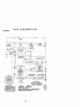
• Check wiring. See electrical wiring
diagram in the Repair Parts section.
TO REPLACE FUSE
Replace with 20 amp automotive-type
plug-infuse. The fuse holder is located
behind the dash.
TO REMOVE HOOD AND GRILL ASSEMBLY
1. Raise hood.
2. Unsnap headlight wire connector.
3. Stand in frontof tractor. Grasp hood at
sides, tilt toward engine and lift off of
tractor.
4. To replace, reverse above procedure.
"Negative"
REPLACING BA'I-FERY
ACAUTtON:
Do not short battery
terminals by allowing a wrench or any
other object to contact both terminals at
the same time. Before connecting battery,
remove metal bracelets, wdstwatch
bands, rings, etc.
Positive terminal must be connected first
to prevent sparking from accidental
grounding.
1. Lift hood to raised position.
2. Remove terminal guard.
26
i
.ood
TO ADJUST CHOKE CONTROL
The choke control has been preset at the
factory and adjustment should not be
necessary, check adjustment as descdbed below before loosening cable. If
adjustment is necessary, proceed as
follows:
1. With engine not running, move choke
control (located on dash panel) to full
choke position.
2. Remove air cleaner cover, filter and
cartridge plate to expose carburetor
choke (See "AIR FILTER" in the
Maintenance section of this manual).
3. Choke should be closed. If it is not,
loosen casing clamp screw and move
choke cable until choke is completely
closed. Tighten casing clamp screw
securely.
4. Reassemble air cleaner.
Noodlig,tWiro
ENGINE
Maintenance, repair, or replacement of
the emission control devices and systems, which are being done at the
customers expense, may be performed
by any non-road engine repair establishment or individual.Warranty repairs must
be performed by an authorized engine
manufacturer's service outlet.
TO ADJUST THROTTLE CONTROL
CABLE
The throttle control has been preset at the
factory and adjustment should not be
necessary. Check adjustment as described below before loosening cable. If
adjustment is necessary, proceed as
follows:
1. With engine not running, move throttle
control lever to fast position.
2. Check that speed control lever is
against stop screw. If it is not, loosen
casing clamp screw and pull throttle
cable until lever is against screw.
Tighten clamp screw securely.
Closed For
Full
TO ADJUST CARBURETOR
The carburetor has been present at the
factory and adjustment should not be
necessary. However, minor adjustment
may be required to compensate for
differences in fuel, temperature, altitude
or load. If the carburetor does need
adjustment, proceed as follows:
In general, turning the adjusting needles
in (clockwise) decreases the supply of
fuel to the engine giving a leaner fuel/air
mixture. Turning the adjusting needles out
(counterclockwise) increases the supply
of fuel to the engine giving a dcher fuel/
air mixture.
IMPORTANT: Damage to the needles
and the seats in carburetor may result if
screw is turned in too tight.
PRELIMINARY SETFING 1. Be sure you have a clean air filter, and
the throttle control cable is adjusted
propedy (see "TO ADJUST
THROTTLE CONTROL CABLE" in Ihe
Service and Adjustments section of
this manual).
Adjusting
Needle
Throttle
Control
Cable
Stop
Control
Cable
Clamp Screw
27
2. Withengine
off turn
idle fuel adjusting
needle In (clockwise) closing it finger
tight and then turn out (counterclockwise) 1 tum.
FINAL SE37"ING 1. Start engine and allow to warm for five
minutes. Make final adjustments with
engine running and shift/motion
control lever in neutral (N) position.
NOTE: The high idle is set at the factory
and cannot be adjusted.
2. Idle soeed settina - With throttle
control lever in slow position, engine
should idle at 1200 RPM. If engine
idles too slow or fast, turn idle speed
adjusting screw in or out until correct
idle is attained.
3. Idle fuel needle settina - With throttle
control lever in slow position, turn idle
fuel adjusting needle in (clockwise)
unti_engine speed decreases and
then turn out (counterclockwise)
approximately 3/4 turn to obtain the
best low speed performance.
4. Recheck idle speed. Readjust if
necessary.
ACCELERATION TEST 5. Move throttle control lever from slow to
last position. If engine hesitates or
dies, turn idle fuel adjusting needle
out (counterclockwise) 1/8 turn.
Repeat test and continue to adjust, if
necessary, until engine accelerates
smoothly.
High speed stop is factory adjusted, Do
not adjust-damage may result.
IMPORTANT: Never tamper with the
engine governor, which is factory set for
proper engine speed. Overepeeding the
engine above the factory high speed
setting can be dangerous. If you think the
engine-goveroed high speed needs
adjusting, contact your nearest Sears or
other qualified service center, which has
proper equipment and experience to
make any necessary adjustments.
28
Immediately prepare your tractor for
storage at the end of the season or if the
tractor will not be used for 30 days or
more.
_CAUTION:
Never store the tractor with
gasoline in the tank inside a building
where fumes may reach an open flame or
spark. Allow the engine to cool before
storing in any enclosure.
TRACTOR
Remove mower from tractor for winter
storage. When mower is to be stored for
a period of time, clean it thoroughly,
remove all dirt, grease, leaves, etc. Store
in a clean, dry area.
1. Clean entire tractor (See "CLEANING"
in the Maintenance section of this
manual).
2. Inspect and replace belts, if necessary
(See belt replacement instructions in
the Service and Adjustments section
of this manual).
3. Lubricate as shown in the Maintenance section of this manual.
4. Be sure that all nuts, bolts and screws
are securely fastened. Inspect moving
parts for damage, breakage and wear.
Replace if necessary.
5. Touch up all rusted or chipped paint
surfaces; sand lightly before painting.
BATFERY
• Fully charge the battery for storage.
• After a period of time in storage, battery
may require recharging,
• To help prevent corrosion and power
leakage during long periods of storage,
battery cables should be disconnected
and battery cleaned thoroughly (see
"TO CLEAN BATTERY AND TERMINALS" in the Maintenance section of
this manual).
• After cleaning, leave cables disconnected and place cables where they
cannot come in contact with battery
terminals.
• it battery is removed from tractor for
storage, do not store battery directly on
concrete or damp surfaces,
ENGINE
FUEL SYSTEM
IMPORTANT: It is importantto prevent
gum depositesfrom forming in essential
fuel system parts such as carburetor,fuel
hose, or tank during storage. Also,
experience indicates that alcohol
blended fuels (called gasohol or using
ethanol or methanol) can attract moisture
which leads to separation end formation
of acids during storage. Acidic gas can
damage the fuel system of and engine
while in storage.
1. Drain the fuel tank.
2. Start the engine and let it run until the
fuel lines and carburetor are empty.
• Never use engine or carburetor cleaner
products in the fuel tank or permanent
damage may occur.
• Use fresh fuel next season.
NOTE: Fuel stabilizer is an acceptable
alternative in minimizing the formation of
fuel gum deposits during storage. Add
stabilizer to gasoline in fuel tank or
storage container. Always follow the mix
ratio found on stabilizer container. Run
engine at least 10 minutes after adding
stabilizer to allow the stabilizer to reach
the carburetor. Do not drain the gas tank
and carburetor if using fuel stabilizer.
ENGINE OIL
Drain oil (with engine warm) end replace
with clean engine oil. (See "ENGINE" in
the Maintenance section of this manual).
CYLINDER(S)
1. Remove spark plug(s).
2. Pour one ounce of oil through spark
plug hole(s) into cylinder(s).
3. Turn ignition key to "START" position
for a few seconds to distribute oil.
4. Replace with new spark plug(s).
OTHER
• Do not store gasoline from one season
to another.
• Replace your gasoline can if your can
starts to rust. Rust and/or dirt in your
gasoline will cause problems.
• If possible, store your tractor indoors
and cover it to give protection from dust
and dirt.
• Cover your tractor with a suitable
protective cover that does not retain
moisture. Do not use plastic. Plastic
cannot breathe which allows condensation to form and will cause your
tractor to rust.
IMPORTANT: Never cover tractor while
engine and exhaust areas are still warm.
29
TROUBLESHOOTING
CHART
PROBLEM
Will not start
CAUSE
1. Out of fuel.
2. Engine not "CHOKED"
properly.
3. Engine flooded.
Hard to start
1.
2.
3.
4.
5.
Enginewillnot
turn over
1. Brake pedal not depressed.
2. Attachment clutch is
engaged.
3. Weak or dead battery.
4. Blown fuse.
5. Corroded battery terminals.
6. Loose or damaged wiring.
7. Faulty ignition switch.
CORRECTION
1. Fifl fueltank.
2. See "TO START ENGINE"
in Operation section.
3. Wait several minutes before
attempting to start.
4. Bad spark plug.
4. Replace spark plug.
5. Dirty air filter.
5. Clean/replace air filter.
6. Dirty fuel filter.
6. Replace fuel filter.
7, Water in fuel.
7. Drain fuel tank and carburetor, refill tank with fresh
gasoline and replace fuel
filter.
8. Loose or damaged wiring.
8. Check all wiring.
9. Carburetor out of adjustment. g. See =ToAdjust Carburetor"
in Service Adjustments
section.
f0.Contact a Sears or other
f0.Engine valves out of
adjustment.
qualified service center.
Dirty air filter.
Bad spark plug.
Weak or dead battery.
Dirty fuel fi]ter.
Stale or dirty fuel.
1,
2.
3.
4.
5.
Clean/replace air filter.
Replace spark plug.
Recharge or replace battery.
Replace fuel filter.
Drain fuel tank and refill with
fresh gasoline,
6. Loose or damagedwiring.
6. Check all wiring.
7. Carburetor
out ofadjustment. 7. See "To Adjust Carburetor" in
Service Adjustments
section.
8. Contact a Sears or other
8. Engine valves out of
adjustment.
qualified service center.
9. Faulty operator presence
switch(es).
1. Depress brake pedal.
2. Disengage attachment
clutch.
3. Recharge or replace battery.
4. Replace fuse.
5. Clean battery terminals.
6. Check all widng.
7. Check/replace ignition
switch.
8. Check/replece solenoid or
starter.
9. Contact a Sears or other
qualified service center.
Engine clicks but
_,ill not start
1.
2.
3.
4.
Weak or dead battery.
Corroded battery terminals.
Loose or damaged wiring.
Faulty solenoid or starter.
1.
2.
3.
4.
Loss of power
1. Cutting too much grass/too
fast.
2. Throttle in "CHOKE"
position.
1
8. Faulty solenoid or starter.
3O
Recharge or replace battery.
Clean battery terminals.
Check all wiring.
Check/replace solenoid or
starter.
Set in "Higher Cut" position/
reduce speed.
2. Adjust throttlecontrol.
TROUBLESHOOTING
CHART
CAUSE
PROBLEM
Lossofpower
(continued)
CORRECTION
3. Build-up of grass, leaves
and trash under mower,
4, Dirty air filter.
5. Low oil leveVdirty oil.
6. Faulty spark plug.
7, Dirty fuel filter.
8. Stale or dirty fuel.
9. Water in fuel.
10.Spark plug wire loose.
11.Dirty engine air screen/fins,
12, Didy/clogged muffler,
13, Loose or damaged wiring,
14.Carburetor out of
adjustment,
15.Engine valves out of
adjustment.
Excessive
vibration
1. Worn, bent or loose blade.
2. Bent blade mandrel,
3. Loose/damaged pad(s).
3. Clean underside of mower
housing.
4. Clean/replace air filter,
5, Check oil leveVchange oil,
6. Clean and regap or change
spark plug,
7, Replace fuel filter.
8. Drain fuel tank and refill
with fresh gasoline.
9, Drain fuel tank and
carburetor, refill tank with
fresh gasoline and replace
fuel filter.
10.Connect and tighten spark
plug wire.
11.Clean engine air screen/
fins.
12, Clean/replace muffler,
13.Check all wiring.
14.See "To Adjust Carburetor"
in Service Adjustments
section.
15. Contact a Sears or other
qualified service center.
1. Replace blade.
Tighten blade bolt.
2, Replace blade mandrel.
3, Tighten loose part(s),
Replace damaged pads,
Engine continues
to run when
operator leaves
seat with
attachment
clutch engaged
1. Faulty operator-safety
presence control system.
1. Check wiring, switches and
connections. If not corrected
contact a Sears or other
qualified service center.
Poor cut - uneven
1. Worn, bent or loose blade.
1. Replace blade. Tighten
blade bolt.
2. Level mower deck.
3. Clean underside of mower
housing.
4. Replace blade mandrel.
5. Clean around mandrels to
open vent holes.
2. Mower deck not level.
3. Buildup of grass, leaves,
and trash under mower.
4. Bent blade mandrel.
5. Clogged mower deck vent
from build-up of grass,
leaves, and trash around
mandrels.
Mower blades will
not rotate
1. Obstruction in clutch
mechanism.
2. Worn/damaged mower
drive belt,
3. Frozen idler pulley.
4. Frozen blade mandrel.
31
1. Remove obstruction.
2. Replace mower drive belt.
3, Replace idler pulley.
4. Replace blade mandrel.
TROUBLESHOOTING
PROBLEM
Poor grass
discharge
-leadlight(s) not
_orking
if so equipped)
CHART
CAUSE
CORRECTION
1. Place throttle control in
"FAST" position.
2. Travel speed too fast.
2. Shift to slower speed,
3. Wet grass.
3. Allow grass to dry before
mowing.
4. Mower deck not level.
4. Level mower deck.
5. Low/uneven tire air pressure. 5. Check tires for proper air
pressure.
6. Worn, bent or loose blade.
6. Replace/sharpen blade.
Tighten blade bolt.
7. Buildup of grass, leaves and 7. Clean underside of mower
trash under mower.
housing.
8. Mower drive belt worn.
8, Replace mower drive belt.
9. Blades improperly installed. 9. Reinstall blades sharp edge
down.
10.Improper blades used.
1O.Replace with blades listed
in this manual.
11.Clean around mandrels to
If.Clogged mower deck vent
holes from buildup of
open vent holes.
grass, leaves, and trash
around mandrels.
1. Engine speed too slow.
1. Switch is "OFF".
2. Bulb(s) or lamp(s) burned
out.
3. Faulty light switch.
4. Loose or damaged wiring.
5. Blown fuse.
3attery will not
;harge
1. Bad battery cell(s).
2. Poor cable connections.
3. Faulty regulator
(if so equipped).
4. Faulty alternator.
Loss of drive
Engine"bacldlres"
_vhentuming
engine
"OFF"
1. Turn switch "ON".
2. Replace bulb(s) or Lamp(s).
3. Checldreplace light switch.
4. Check wiring and connections.
5. Replace fuse.
1. Replace battery.
2. Check/clean all connections.
3. Replace regulator.
4. Replace alternator.
;1, Freewheel control in
=disengaged" position.
2. Motion drive belt worn,
damaged, or broken.
3, Air trapped in transmission
during shipment or
servicing.
t. Engine throttle control not
set at "SLOW"
position for 30 seconds
before stopping engine,
32
1. Place freewheel control in
=engaged" position.
2. Replace motion drive belt.
3. Purge transmission.
1. Move throttle control to
=SLOW" position and allow
to idle for 30 seconds before
stopping engine.
TRACTOR -- MODEL NUMBER 917.272244
SCHEMATIC
BATTERY
AMMETER
_IIFUSE
I©:_
CLUTCH I BRAKE
(PEDAL UP)
_ __
......
J
SOLENOIO
....
_C
SEAT SWITCH
{NOT
:=__
STARTER
G '
i
O_CUPIED)
i A
_b
i
,
_
i
t-
Id
EUECTRIC CLUTCH
E
_,
PTO [DISENGAGED)
_u_
i
FUEL
II
'
LINE '
,
_¢_
_
I 85
f
:
', _BTA
IGNITION
UNIT
_-UEL gH=U_,_=g
J
=
86
;
OPERATOR PRESENCE
SPARK
_
I
i
.........
_
F_
PLUG
GAP
RELAY ON
#1
_(2
pLUGS
TWIN CYL ENGINES)
(IF SO EOUIpRED)
_c,_
L-
_
IIALTERNATOR
'l
PTO SWITCH
HEAD4-1GHTS
FOSlTlON
OFF
ON
CIRCUJl"
C+G,B_H
C_FrB_ErA÷D
G F C
IGNITION SWITCH
CONNECTIONS
CONNECTIONS
WIRING
INSULATEDNON-REMOVABLE
CLIPS
REMOVABLE
NOTE: IF WIRING iNSULATED CLIPS WERE REMOVED FOR
SERVICING OF UNIT, THEY SHOULD BE REPLACED TO
PROPERLY SECURE YOUR WIRING,
33
H
D
D A
TRACTOR
-- MODEL NUMBER 917,272244
ELECTRICAL
I
i
i
i
i
/
//
jt
s/
34
TRACTOR -- MODEL NUMBER 917.272244
ELECTRICAL
KEY PART
NO. NO,
DESCRIPTION
1
2
8
10
11
12
16
21
25
26
27
28
29
3o
33
4o
42
45
46
5O
55
79
81
Battery
Boit, Hex 1/4-20 x 3/4
Tray, Battery
Bolt, Btr Front 1/4-20 x 7-1/2
Holddown Battery Front Mount
Nut, Push Ny$on Battery Front 1!4
Switch Interlock Push-In
Harness. Light
Cable, Battery
Fuse
Nut Keps Hex 1/4o20 UNC
Cable, Ground
Switch, Seat
Switch, Ignition
Key
Harness, Ignition
Cover Terminal
Ammeter
Hourmeter
Switch Pto
Screw Thdrol 5/16-18x 1/2
Bulb _d Holder Asm Halogen
Relay Asm
163465
74760412
7603.1
145211
150169
145769
153664
175449
176909
175158
73510400
145491
160784
175442
175447
178452
154336
177500
177501
178461
17490508
175448
109748)(
NOTE: All component dimensions given in U.S. inches
1 inch = 25.4 mm
35
TRACTOR -- MODEL NUMBER 917.272244
CHASSIS AND ENCLOSURES
42
29
23
36
TRACTOR -- MODEL NUMBER 917.272244
CHASSIS AND ENCLOSURES
KEY
NO.
PART
NO.
DESCRIPTION
1
2
3
9
10
11
13
14
17
18
20
23
25
26
28
29
30
31
37
38
39
42
43
58
09
64
74
142
143
144
145
t54
155
156
157
158
159
156
206
207
209
215
174619
176554
17090612
172542X418
STD533710
174996
179174X010
17490608
172540X615
125938)(
156437
124028X
19131312
STD541437
174945X418
174944X418
175692X615
139976
17490508
175710
174988
172545X599
172544X599
174993
STD533707
174997
STD541437
175702
154966
175582
156524
174679
174680
163805
163806
162037
155123)(418
164863
170165
17670508
1700C612
172543X615
Chassis
Drawt_r
Screw. 3/6-16 x 3/4
Dash
Bolt RDHD SQNK 3/8-16unc x 1
Panel, Dash, LH
Panel. Dash, RH
Screw Tndrol 3!8-16 x 1]2
HOOdAssembly
Bumper Hond
Plate Batted/
Bushing Snap
Washer 13/32 x 13/16 x 12 Gauge
Locknut, Hex, with Insert 3/8-16 UNC
GrilLe
Lightbox Dual
Fender/Footrest
Bracket, FendedSupport
Screw. Thdrol, 5/16-18x 1/ZTYT
Bracket Asm Pivot Mower Rear
Bracket Pivot Hood
Lens Lh
Lens Rh
Duct Hoed
Bolt Rdhd Sqnk 3/8+16 UNC x 3/4
DashLower
Nut Crownlock 3/8-16 UNC
Plate Reinforcement
Brackel Swayhar Chassis
Bracket Footrest
Rod Pivot Chassis/Hood
Bracket Dash Rh
Bracket Dash Lh
Striker Plate
Magnet YTGT
Parking Brake Bkrt
Cupholder Stl BIk
HWHDH;-Lo.#13-16 x 3/4
Bolt Shoulder 5/16_18
Screw Tndrol 5/16-18 x 1/2
Screw Hexwsh Thdr 3/8-16 x 3/4
Bump_"
NOTE; All component dimensions given in U.S. inches
1 inch = 25.4 mm
37
TRACTOR
-- MODEL NUMBER 917.272244
GROUND DRIVE
214_
55
77
26
241
74
26
30
38
TRACTOR -- MODEL NUMBER 917.272244
GROUND DRIVE
KEY
NO.
PART
NO.
1
......
9
15
16
17
19
20
21
22
24
25
26
27
28
29
30
32
33
34
35
38
37
38
39
40
41
42
47
48
49
50
51
52
53
55
56
57
59
61
62
63
65
66
74
75
DESCRIPTION
Transaxle (See Breakdown)
Hydro gear Model 323-0510
174367
Clutch Ele¢
74490544
Bolt Hex Flghd 5/16-19 Gr. 5
73800500
Nut Lock Hex W/Ins. 5/16-18 Unc
126197X
Washer 1-1/20D x 15/32 ID x
.250
73800600
NutLockHexW/Wsh
3/8-16Unc
173937
Bolt Hex 7/16-20 x 4 x Gr. 5-1.5
175036)(505 KnobCustomControICnJise
175896
Rod, Brake
73350600
Nut, HexJam 3/8-16Unc
106888X
Spdng, Brake Rod
19131316
Washer
76020412
Pin Cotter 1/8 x 3/4 CAD.
179607
Rod, Parking Bra.'<e
179608)(505 KnobBrakeParking
169592
Bracket, Transa.xle
74760512
Bolt Hex Hd 5/16-18 Uric x 3/4
72140506
Bolt Rdhd Sqnk 5/16-18 Unc x 3/4
175578
Shaft, Foot Pedal
120183X
Bearing,Nylon
19211616
Washer
1572H
PLn,RoLl
165936
Pulley, Composite, Flat
74760648
BoR Fin Hex 3/9-19 Unc x 3
175461
Spacer, Split
175556
Keeper, Belt Idler Rat
19131312
Washer 13/32 x 13/16 x 12 Ca,
127783
Pulley, Idler, V=Groove
154407
Bellcrank Clutch Grad DtW Stl
123205X
Retainer, Belt
74760624
Bolt
73660600
NutCrownlock 318-16UNC
73680500
Nut, Crownlock 5/16-18Unc
105710)(
Unk, Clutch
105709X
Spring, Return, Clutch
17060616
Screw 3/8-16 x 1.0
140294
V-Belt, Ground Drive
169691
Keeper, Center Span
17060612
Screw 3/8-16 x 3/4
123533X
Cover, Pedal
175417
Pulley, Engine
10040700
Washer
154778
Keeper Belt Engine
137057
Spacer, Axle
121749X
Washer 25/32 x 1-114 x 10 Ga.
KEY
NO.
PART
NO.
DESCRIPTION
76
77
78
89
90
95
96
116
120
150
151
202
212
214
215
217
210
219
220
221
222
223
224
225
229
227
229
229
230
231
232
233
334
235
236
237
238
239
240
241
242
243
244
12000001
12_3583X
121748X
174901X419
124346X
175899
4497H
72140608
73900600
175456
19133210
72110612
145212
174735
175646
179433
174713
174839
174711
72140606
73680700
t 74840
174736
174712
174_Y2
174710
171873
176451
17060512
174573
175570
174856
174858
174857
129903
170165
176807
17490508
175610
73930400
74780412
176289
17060508
E-Ring
Key, Square
Washer 25/32 x 1-5/8 x 16 Ga.
Console, Shift
Nut Self-Thd Wsh-hd 1/4 Zinc
Rod Bypass
Retainer Spdng 1" Zinc!Cad
BoaRDHDSQNK3/8-16Uncxl
Nut Lock Fig 3/9-16 Unc
SpaeerRetainer
Washer 13/32 x 2 x 10 Ca.
BoltCarrSh3/8-16xl-l/2Gr.
5
Nut HexFlange Lock
Unk Transa.xle
CoverPedalForward
Pedal Reverse Asm W/Pad
ArmBontrolPedalReverse
Bracket Frest PdlCtrl. Hy0
Bracket Mtg. Pedal Control
Bolt Rdhd Sqnk 3/9-16 Unc x 3/4
Nut Crownlock 7116-14 Unc
Washer Nylon 11/16 ID x .060
Pedal Forward
Arm Cent tel Pedal Forward
Bolt Pivot Spacer
Cam Reverse PedalLT
BoltShoulders/16-tB
Washer Serrated 5/16 x .75
Screw5/18-19
StrapTorque
Actuator Cruise Disengage
PawlConlrolCruise
Lever Control Cruise
SectorControlCruise
BoltShoulder3/8-16Unc1/44
Bolt Shoulder 5/16-18
Arm Mtg. Cruise Sector
Screw Thdrol 5/16 x 1/2
Spring ReturnCruise control
Nut Centedock 1/4-20 Unc
Bolt Fin Hex 1/4-20 Unc x 3/4
Bracket Anti-Rotation CVX
Screw 5/16-16 x 1/2
NOTE: All component dimensions given in U.S. Inches
1 inch = 25.4 mm
3,9
TRACTOR
STEERING ASSEMBLY
-- MODEL NUMBER 917.272244
72
4O
TRACTOR -- MODEL NUMBER 917.272244
STEERING ASSEMBLY
KEY
NO.
PART
NO,
DESCRIPTION
1
2
3
4
5
6
8
10
11
12
13
15
17
29
32
33
34
35
36
37
38
40
41
42
43
46
65
67
68
71
72
82
87
88
91
175139)(418
172393
169840
169839
6266H
121748X
12000029
175121
STD551137
73940800
136518
145212
177883
17060612
170162
19111216
STD551131
73540500
155105
152927
175140X418
STDF_1537
159945
174530X418
121749X
121232X
160367
72140618
169827
175146
19182411
169835
173966
175118
175553
Steering Wheel
Axle Assembly
Spindle Assembly, L.H.
Spindle Assembly, R.H.
Beadng, Race, Thrust, Hardened
Washer 23/32 x 1-_8x 16 Gauge
Ring, Klip
Dmglink
Washer, Lock
Nut Hex Jam Toplock 1/2-20 Unf
Spacer Brg Axle Front
Nut Hexl_nge Lock
Shaft Assembly, Steering
Screw, 3/8-16 x 3/4
Rod,Tie
Washer 11/32 x 3/4 x 16 Ga.
Washer Lock Hvy Spr. 5/16
Crownlock Nut 5/16-24 Unf
Bushing, Steedng
Screw
Insert, Steering Wheel
Nut Lock Center 3/8-24 Unf
Adaptor, Steering Wheel
Boot, Steedng Shaft
Washer 25/32 x %114 x 16 Gauge
Cap,Splndle
Spacer Brace Axle
Bolt Rdhd Bq 3/8-16 UNC x 2-1/4
Axis. Brace
Steering Asm
Washer 9/16 Id x 1-1/20d 11 G Zin
Bracket Susp Chassis Front
Washer Flat .781 x 1-1/2 x .14
BoltShoulder7/16-20Unc
CJ_pSteedng
NOTE:
All component
1 inch = 25,4
dimensions
mm
41
given
in U.S.
inches
TRACTOR -- MODEL NUMBER 917.272244
ENGINE
OPTIONAL
EQUIPMENT
29/
39
__
Spark Arrester
42
TRACTOR -- MODEL NUMBER 917.272244
ENGINE
KEY
NO.
4
5
6
8
10
13
14
16
17
23
25
26
29
31
33
34
37
38
39
45
81
101
102
111
PART
NO.
DESCRIPTION
175439X505 Control,Throttle
Englae, ISee Breakdown) Kohlar Model Number
CV624-65578
149723
Muffler
146699
Pipe Exhaust Lh
140"700
Pipe Exhaust Rh
171877
Bolt 5/16-18 Uric x 3/4
146629
Sh_elclHeat
24=041-02
Gasket Kohlar CV 18-CV26
(Eae Engine Breakdown)
148456
Tube Drain Oil Easy
11050600
Washer. Lock, External Tooth 3/8
17490624
Screw Thdrol 3/8-16 x 1-1/2
169837
Shield, Browning/Debris Guard
175441 X505 CbekeControl
73920600
Nut Keps 3/8_24 L=NF
137180
Kit, Spark Arrestor
157103
Tank Fuel
161696
CapAsmFuel
123487X
Clamp.Hose
106082X
Pad, Spacer
8543R
Line. Fuel
148315
Plug Drain Oil Easy
109227X
Pad. Idler
17000612
Screw Hexwsh Thdr 3/8-16 x 3/4
73510400
Nut Keps Hex 1/4o20 UNC
M73030800 NOt Flange M8-1.25
164863
Screw Hwhd H.-Lo #13016 x 3/4
10010500
Washer Split
NOTE: All component dimenslans given in U.S. inches
1 inch = 25.4 mm
43
TRACTOR - - MODEL NUMBER 917.272244
SEATASSEMBLY
KEY
NO.
PART
NO,
DESCRIPTION
1
2
3
4
5
6
7
8
9
10
11
12
13
175134
140551
71110616
19131610
145006
STD541437
124181X
17000616
19131614
174894
177957
121246X
121248X
Seat
Bracket, Pivot, Seat
Bolt
Washer 13/32x lxl0Gauge
Clip, Push-In Hinged
Nut
Spdng, Seat
Screw 3/8-16 x 1-1/2
Washer 13/32 x 1 x 14 Gauge
Pan, Seat
Knob,Seat
Bracket, Switch Mounting
Bushing, Snap
KEY
NO.
PART
NO.
14
15
16
17
18
21
22
24
72050412
121249X
123740X
123976)(
124238X
171852
STD541431
19171912
25
127018)(
DESCRIPTION
Bolt, Carriage 1/4-20 x 1-1/2
Spacer, Split
Sp_ng
Locknut, Flange 1/4Grade5
Cap Spdng Seat
Bolt, Shoulder 5/16-18 UNC
Nut
Washer 17/32 x 1-3/16 x 12
Gauge
Bolt, Shoulder 5/16-18 x .62
NOTE: All component dimensions given in U.S. inches
1 inch = 25,4 mm
44
TRACTOR -- MODEL NUMBER 917.272244
DECALS
15
1
13
19
\
18
10
7
16
9
12
14
25
24
KEY
NO.
PART
NO.
DESCRIPTION
KEY
NO,
PART
NO.
DESCRIP'nON
1
2
3
4
5
6
7
8
9
10
12
13
14
15
16
17
177888
174969
1779O9
177910
177917
133644
178989
177916
177967
156439
146046
177890
175291
177254
138047
164757
Decal,Hood/Seat
Reflector LH.
Decal Hood, R,H.
Decal, Hood, LH.
Decal, Engine HP LH
Decal. Customer Maintenance
Decal. Seat
Decal. Engine HP RH
Decal. Dash Lower
Decal, Fender Danger
Decal. V-Belt Drive Schematic
Decal Strg Wheel
Decal, V-Belt Schematic
DecalReplc
Decal, Battery Diehard
Decal. Hp Engine
18
19
20
21
22
23
24
25
26
27
--*
-*
----
177913
177918
149516
177889
174970
177955
178482
178455
177914
177915
138311
174998X418
175542)(418
169210
180171
180172
Decat, Panel Side
Decal, Engine
Decal, Battery Dngr/Psn Eng
Decal, Grille
Reflector RH
Decal, Fender Oper Cruise
Decal, Hvy Duly
Decal, Deck Caution Tension Arm
Decal, Engine
Decal, Engine
Decal, Lift Handle
Pad Footrest LH
Pad Footrest RH
Decal, By Pass Lt Hydro
Owner's Manual. English
Owner's Manual, Spanish
KEY
NO.
PART
NO.
DESCRIPTION
1
2
3
4
59192
65139
177750
59904
WHEELS
& TIRES
4,10
5
6
7
tl
9
g
10
11
--
Valve Cap, Tire
Stem, Valve
Tire,Front
Tube. Front Tim
(Not Provided, Service Item Only)
1C6732X417 Rim, Front
278H
Fgting. Grease ( Front Wheel Only)
9040H
Bearing, Flange (Front Wheat
Only)
106108X417 Rim, Rear
177751
Tire, Rear
7152J
Tube, RearTire
(Not Provided. Service Item Only)
104757X417 Cap. Axle
144334
Sealant, ]3re 10 oz.
NOTE: All component dimensions given in U.S. inches
1 inch = 25.4 mm
45
TRACTOR -- MODEL NUMBER 917.272244
LIFTASSEMBLY
51
49
20_
46
O
TRACTOR
-- MODEL
NUMBER
917.272244
LIFTASSEMBLY
KEY
NO.
PART
NO,
DESCRIPTION
1
2
3
4
5
6
7
11
12
13
15
16
17
18
20
31
3_
36
37
38
40
41
49
51
52
53
54
176263
159476
178981
1200O0O2
19211621
120183X
175830
175370
175371
4939M
175562
73350800
175689
73800800
163552
176205
175994
155097
123935X
17060516
19112410
155098
145212
19171416
175378
175802
175560
PlungerAssembly
Shaft Assembly, Uft
Pin, Groove
E-R_ng
Washer 21/32 x 1 x 21 Gauge
Bearing,Nylon
Grip, H_nd_e, FlUted
Link, Lift. L.H.
Link, Uft. R,H.
Retainer Spring
Plate Asm Suspension Front
Nut Jam Hex 1/2-13 Uric
Trunnion Front Susp.
Nut Lock w/Wsh 1/2-13 Uric
Retainer Spring
Trunion Sups.Arm,
Nut Lift Link 7/16-20
Pointer Height Indicator
Plug Hole
Screw 5/16-18 x 1
Washer 11132 x 1-1/2 x 10 Ga
Indicator Height Silt
Nut Hex/Large L0Ck
Washer 17/32 x 7/8 x 16 Ga.
Arm Suspension Rear LH
Arm Suspension Rear RH
Pin Flange
NOTE: All compenent dimensions given in U.S. inches
1 inch = 25.4 mm
47
TRACTOR
-- MODEL NUMBER 917.272244
MOWERDECK
46
130
112
i
21'
114
\
I
. 11_
116
_
29 2
19
18
48
24
"\
TRACTOR
- - MODEL NUMBER 917.272244
MOWERDECK
KEY
NO.
PART
NO.
DESCRIPTION
1
3
5
6
8
11
13
14
15
16
17
18
19
20
21
24
25
26
27
28
29
30
31
3_
33
36
37
39
42
43
45
46
47
48
49
50
52
53
174348
138017
4939M
130832
174365
173920
174360
174358
110485X
174493
72110610
72140505
132827
174378
73680500
105304X
178102
110452X
174346X428
19111016
131491
173984
129963
177865
178342
19131318
177968
174375
165723
174373
174343
137729
174369
174368
73680600
72110612
175820
19131312
Deck Weldment Mower 48
Bracket Asm.. Sway Bar
Retainer Spring
Arm, Suspension, Rear (Sway Bar)
Bolt7116 Asm. Blnde
Blade
SheR MandrelAsm. Greaseable
Housing Mandrel
Beadng, Ball Mandrel
Btdpper Mandrel Deck
Bolt RDHD Sq Neck 3,/8-16 x 1.25
Bolt, Carriage 5/16-18 x 5/8
Bolt, Hex Hd. Shoulder 5116-18
Baffle. Vodex Mower
Nut, Crowninck 5/16-1BUNC
Cap, Sleeve
Spdng,Torsion
Nut, Push
DeflectorShield
Washer 11/32xs*Bx
16Ga.
Rod, Hinge
Screw Thd Roll Hex
Washer, Spacer Mower Vented
Pulley, Mandrel
Nut, Fig. Top Lock Cntr, 9/16
Washer 13J32x13!16x16Ga.
Pulley, Idler
Polley. Idler, Driven
Spacer, Retainer
Arm, Idler Secondary
Cover, Mandrel Deck
Screw, ThdrolL 114-20 x 5/8
V-Belt, Mower, Secondary
V-Belt, Mower, Primary
Nut, Crownlock 9/8-16 UNC
Bolt, Cart. 3/8-16 x 1ol/2 Gr. 5
Pulley Idler Fiat
Washer 13/32 x 13/16 x 12 Ga
KEY
NO.
PART
NO,
54
55
56
57
99
91
92
93
94
95
97
98
99
100
107
108
109
110
112
113
114
115
116
117
118
119
121
122
126
130
1BO
74780616
72140608
155986
156941
74760516
175384
73800600
19171416
176066
175996
133943
174370
175080
72110616
175294
72110404
73680400
175016
174387
72110508
174384
174609
137644
174873
73930600
19121414
174371
174996
174372
17060616
73800500
175312
174356
DESCRIPTION
BOltFia Hex 3/8-16unc x 1 Gr 5
Bolt RDHD SQHK 9/6-16unc x 1
Bar Pnt Adj.
Pin Head Rivet
BoR Hex 5.16-18 x 1
Bracket Asm Noseroller LH
Nut Lock Hex W/Ins 9/6-16 Unc
Washer 17/32 x 7/8
Nose.roller
Bracket Asm Noseroller RH
WasherHardened
Spring Primary Drive
Pulley Idler'V'
Bolt RDHD Sqnk 3/8-16 UNC x 2
BaffieVacEdgeMower
BoltCart,
Nut Crownlock 1/4-20
Arm Spring Secondary
LinkTensionReliefLever
BoltCarr. 5/16-18xl
Tension Asm Reliaf Lever
Arm Spring Tension Relief
Bolt, Shoulder
Gauge Wheel
Nut, Centedock 3./8-16 UNC
Washer 3/Sx7/Sx14Ga.
Sphng Secondary Drive
Bushing PivotTensinn Relief
Arm, Idler, Primary Deck
Screw 3!8-16 x 1,0
Nut Lock 5'16-18
Replacement Mower, Compieta
Mandrel Asm, Service (Includes
Key Nee. 13-15)
NOTE: All component dimensions given in U.S. inches
1 inch = 25.4 mm
49
2:
,.<
o
G)
12(
.4 j129
128
rrl
-n
-,I
..rl
mo
' _0
=
Z=,
88
i
oz_
mO
PN
Zr-
_19
tom
,124
16
99
_SeaJant (Join1 d' etancheite)
57-20W50 Oil. 7S,a OZ (OZ de 78.820 d' Hu_le)
127 - Seal Ind O-rln g Kit (Phoque 0 Sonne Jeu)
TRACTOR -- MODEL NUMBER 917.272244
HYDROGEAR TRANSAXLE- - MODELNUMBER323-0510
KEY PART
NO. NO.
1
2
3
4
5
6
7
8
9
10
11
12
13
14
170351
170352
170353
170354
169898
170355
170356
170357
170358
170359
170360
169870
170361
169869
16
170362
17
16
19
23
24
27
28
29
30
31
3_
170363
178781
150771
170365
170366
170367
170368
170369
170370
170371
170389
33
34
35
36
37
38
39
40
41
42
43
44
142991
170390
170391
170392
150792
156793
150809
170393
170394
170395
170396
t 50797
45
46
47
48
49
50
51
52
170397
170398
170399
170400
170401
170402
170403
170404
53
54
55
56
57
58
59
60
61
62
63
170405
170406
142977
142978
150798
170407
170408
142883
142882
142887
170410
64
65
66
67
142892
170411
170412
170413
DESCRIPTION
Main Housing, Assembly
Side Houstag, Assembly
Center Section, Assembly
Swa.shplata,Trunion Mach_ned
Block - Assembly
Sealant 10.50z
Hex Flange Screw 1/4-20 X 1,25
Stud, 5/16-24 Hex Double End
Shaft, Input
Ring - Retaining
Spacer
Ring* Retaining
Seal, LJp .67 X 1.58 X ,276
Ball Brg 17ram Id X 40mm Od X
12ram
Hex Flange Head Screw 5J1624X0.75
Lip Seal 18X 32 X 7
Arm,Cantral
Beadng, 30x52x13 Thrust
Check Plug Assembly, Washer
Shaft, Motor
Gear - Pinion, 131
10tJ48tGear
Gear. 10t Jackshaft
6or Ball Gear
Sleeve Bearing .75 X 1.575 X .625
$iaeveSea dng(Outboazd)
,75xl .750x.625
Washer, 3/41d X 1-1/2Od X .13Thk
Lip Seal Axle Seal
Shaft. Axle 25 X 11.39 (Key,R.H.)
Shaft, Axle .75 X 16,99 (Key,L.H,)
Miter Gear (Spfined)
Miter Gear 16t (0.5 Id)
Shaft
Rir'.g,Splral Retaialng
Pin, Jackshaft
Magnet, Ring
Spring, Bypass
Hydro Mtg Screw 3/6-24 X 2.5
Long
Filter
Base, Fifler
Actuator, Bypass
Rod, Bypass Actuator
Arm. Bypass
Retaining Ring .250 External
Seal, Lip .741 X .250 X ,260 TC
Flat Washe_. 5/8 Id X 1.00d X
.65 Thk
Retaining Ring
Searing, Center Block
Spring - Helical Compression
Waspar
20w-5OOft
Brake Yoke
Rotor, Brake
Brake Puck
Puck Plata
Brake Actua6ng Pia
Hfhc.s 1/4-20x2 W/
Patch,SpecialRange
Bolt, I/4-20 X 1 W/Patch
SpaCer
Spring. Brake Aml Bias
Sq. Hd, Boft5!16-24*Ribbed
KEY
NO.
PART
NO.
68
69
70
71
178782
170415
170416
170417
72
73
74
75
170418
142884
170419
t 70420
76
77
70
79
80
170421
170422
142969
142960
150776
61
82
170423
170424
83
04
85
87
88
90
9G
94
95
161168
170425
170426
142917
170429
170430
170431
178783
176784
96
97
98
99
100
101
108
103
107
108
178786
178787
178789
178792
176793
178794
176795
178796
170432
170433
109
111
113
114
116
117
119
120
121
122
123
124
17PA34
170435
170437
178797
170438
176799
170439
170440
170441
170442
176800
170444
125
126
127
126
130
131
132
133
134
_
170445
170446
170447
173165
178802
176803
178804
178806
178808
173839
DESCRIPTION
Arm, Brake
Slotted Hex Nut 5/16-24
Cotter Pin 3/32 X 3/4
Compression Spdng Brake AntiDrag
Washer, Ht .5 I,D. X 10.D. X .032
Flat - Washer 11/32 I,D. X 7/fl O,D
Oil Seal .625 X 1.0 X .25
Check Plug Assembly, .027,
Washer
Stud, 5/16-24 Friction Pack
Puck, 330 X 1,50 X ,0975
Spdng, Helical Camp
Spacer
Hex Lock Nut 5/16*24Unjf (Nylon
Insert)
Wedge, Friction Pack
Clip, Washer .316x 1,50x.1046
(Plated)
Pin, Standard Headless
Fit6ng, 5/16 Sae 5/32 Tube
Hose. Expansion Tank
Cap - Poppat VaNe
Belt, Sefl Tapping 10-32 X 1/2
Puck, Inner Wedge
Spring Clip - Housing Thrust
Bearing, Ball
Screw, Socket Head Cap 5/1624X1-1/2
Spacer, Locating
Screw, SFHCS 5/16-16 X1
Arm Return
Puck, Adjusting
Washer..24 ID X 1,60 OD X ,239
Spring. Extension
Spacer ,260 ID X .560 as X ,870
Bracket*Torque
Deflector
Washe6Motar Shaft
.71k_Xl.15odx.O3Othk
Plug, Sae #6
O-Ring .07X ,301 I,D.
Bracket, Support Expansion Tank
Spdng
SiliconSponge
Pin. Spring
Fan. 7 In.
Pulley
Hex Lock Nut 1/2-20 (Nylon Inserl)
Washer, Balleville
Belt Keeper
Center Section-Fi8er-Sypass
Assembly
FiflerAssembly
Fan - Pultay Service Assembly
Seal - O-Ring Kit
Kit, Expansion Tank
Stud Ball
Bracket, Cruise Oampar
RexNutsi16-18NC
Damper
Washer, Helical Spring Lock 5/16
Transaxle Complete
NOTE: All component dimensions given in U,S. inches
1 Inch = 25,4 mm
51
TRACTOR -- MODEL NUMBER 917.272244
KOHLER ENGINE-MODEL NUMBER CV624 TYPE NUMBER 65578
c;_iNdOr[:D_rEi_
D';:uL;aE_Net RRE_f/: r[; I
/t
j
10
L--
I
0--ii
TRACTOR -- MODEL NUMBER 917.272244
KOHLER ENGINE-MODEL NUMBER CV624 TYPE NUMBER 65578
HEAD/VALVE/BREATHER
CRANKCASE
KEY
NO.
KEY
NO.
PART
NO.
1
2
24-032o01-S
3
4
24-294-13-S
24-380-13-S
5
24-067-13-S
24-067-14-S
24-874-17_S
Connecting Rod (Std.) (2)
Connecting Rod (.25) (2)
Piston w/Ring Set Std. 2
(Inctudes 7, 8)
24-874-18-S
24-874-19-S
24-874-14-S
24-108-11-S
24-108-12-S
24-108-13-S
24-018-01-S
12-422-09-S
Piston wiring Set .25 2
P_ston wiRing Set .50 2
Piston wiring set {.08 I
Ring Set (Std.) (2)
Ring Set .25) 2
Ring Se_ .50) (2)
Reta net, pston p n 4)
Shim, camshaft (A.R.)
12-422-13-S
12-422-07-S
Shim, camshaft (A.R.)
Shim, camshaft (A.R.)
12-422-08-S
12-422-10-S
Shim, camshaft (A.R.)
Shim, camshaft
10
11
12-422-11-S
12-422-12-S
24-012-10-S
52-139-0g-s
Shim,
Shim, camshaft
camshaft IAARRI
'. i
Camshaft
Plug, cup
12
M-545010-S
13
14
15
16
17
18
24-018-04-S
24-402-05-S
12-153*01-S
24-126-19-S
12-123-04-S
M-545016-S
19
20
12-153-02-S
24-038-04-S
Screw, hex. llange
MSx0.8xl0
(21
Retainer, reed (2)
Reed, breather (2)
O-Ring, lower oil fill tube
Bracket. oil fill tube
Tube, oil fill
Screw, hex. flange
M5xO.8x16
O-Ring. upper oil fill tube
Dipstick assembly (Includes
21. 22)
21
22
23
24
25
26
27
24-755-46-S
12-153-03-S
24-018-09-S
M-931010-S
28-032*09-S
24-468-15-S
24-144-33-S
PART
NO.
24-033-01-S
2
3
4
5
24-041-23-S
24-096-59-S
25-139°60-S
M-645020
25-351-01-S
24°755-66-S
8
9
10
11
12
13
24-411-05*S
24-041-08-S
24-318-12-S
25-186-01-S
24-599-01-S
14
12-086-16-S
15
24-755-74-S
16
17
18
19
2O
21
22
23
24
25
26
27
M-640034-S
DESCRIPTION
Kit, breather cover w/gasket
(Includes 24)
Gasket, breather
Cover, breather
Plug, allen hd. 1/8"
Screw, hex. flange
M6xl.0x20
(4)
Uftar, valve (4)
Kit, valve train (Includes
8,1,,t21
Rod, push 14)
Gasket, cylinder head (2)
Head assembly, #2 cylinder
Arm, rocker (4
Pivot, rockerarm
4
Screw, hex. flange
M6x1.Ox34 (4)
Screw, hex. flange
M10xl.5x9O
(8)
Kit, valve cover - plain
(Includes 16,171
24-086-32*S
24-153-16-S
24-445-01-S
24-016-01-S
24-016-02-S
24-017°01-S
24-017-02-S
24-032-05-S
238011-S
24*089-02*S
12-173-01*S
12-755-03-S
Screw,
G-Ring shoulder (4)
Strap, lifting
Valve, exhaust (Std.) (2)
Valve, exhaust (.25) (2)
Valve, intake (Std.) (2
Valve, Intake (.25) (21
Seal, valve stem 2)
Retainer, spring 4
Spring, valve (4)
Cap. valve spring 4
Kit, retainer (4)
24-318-11-S
24-755-76-S
Head assembly, #1 cylinder
}(it, valve cover - breather
(Incl. 16,17,28)
Grommet, rubber
Kit, breather separator
(Includes 28,30-33)
28
29
25-313-02-S
24-755-57-S
3O
M-545016-S
31
32
33
34
35
36
37
24-445-02-S
24-126-44-S
24-112-12-S
24*294-06-S
24-326-13-S
24-326-14*S
25-237-14-S
6
Screw, hex. flange
M5x0.8xt6
(2)
Strap, breather
Bracket, breather separator
Spacer
Fifting
Hose, breather
Hose. breather
Clamp, hose (2)
7
8
9
DESCRIPTION
Seal oil front
Crankcase
(USE; Miniblock 24 782 24)
Fiftin
Pin, o_owel locating (6)
I I}l
Kit. oil fill cap (includes 22)
O-Ring, dipstick
Retainer, nng
Washer. nylon (top)
Seal, governor cross shaft
Washer (bottom)
Shaft, governor cross
NOTE: All component dimensions given in U.S.
inches 1 inch = 25.4 mm
53
TRACTOR - - MODEL NUMBER 917.272244
KOHLERENGINE-MODELNUMBER CV624TYPE NUMBER65578
_GNII"IONJELECTRICAL
3'allumaoe
ou Electriaue
i
SLOWER HOUSING AND BAFFLESI
Rabitation de $ourtleur et Ddcalentl
0--6
d ._O
=-,
54
TRACTOR -- MODEL NUMBER 917.272244
KOHLERENGINE-MODELNUMBERCV624TYPE NUMBER65578
IGNrrlON/CHARGING
KEY
NO.
PART
NO.
1
54-755-15-S
2
M-403025-S
3
4
5
X-25-92-S
24-112-04-S
25-086-47-S
6
7
24-157-03-S
12-086-14-S
8
9
10
11
12
13
12-468-03-S
X-42-15-S
24-025-04-S
25-403-03-S
X-25-92-S
24-085-18-S
14
15
236602-S
54-755-09-S
16
17
12-132-06-S
M-548025-S
10
19
20
21
22
235173-S
48-154-02-S
X-25-63-S
24-504-01-S
M-545020-S
BLOWER
DESCRIPTION
Kit, grass screen
(Includes 2-4,and 24 113
18-S)
Screw, hex. cap M4x0,7x25
(4)
Washer, plain 3/16" (4)
Spacer, grass screen (4)
Bolt, shoulder M6 X1,0 X15
S(4)
Fan
Screw, hex. flange
M10xl.5x46
Washer, plain 3/8".
Key
Flywheel
Rectifier-regulator
Washer, plain 3/15" (2)
Screw, phillips hd. 11-16x7/
0 (2)
Connecter (3 contact)
Kit, 15 amp stator
(Inctudes 24 126 71-S)
Spark Plug (2)
Screw, hex, cap M5xO,Sx25
HOUSING
KEY
NO.
PART
NO.
1
24-027-20-S
2
3
4
5
24o100-01-S
25-139-10-S
24-10g-02-S
M-545020-S
6
M-545016-S
7
M-551016-S
8
M-645016-S
9
10
11
24-146-16-S
24-14g-20-S
24-063-20-S
12
13
24-063-14-S
24-003-58-S
14
15
24-g63-23-S
M-545010-S
& BAFFLES
DESCRIPTION
Housing, blower
(Incl. 2-4)
Nut plastic (3)
Plug, button 9/16
Nut, plastic (2)
Screw, hex, flange
M5x0.Sx20 (4)
Screw, hex. flange
M5xO.Bx16 (3)
Screw, hex. flange
M5x0.Sx16
Screw, hex. flange
Mgx1.0x15 (5)
Plate, backing - # 2 side
Plate, backing - # 1 side
Baffle, cylinder barrel-# 2
side
Baffle, valley - #2 side
Baffle, cylinder barrel-# 1
side
Baffle, valley - #1 side
Screw, hex. flange
Mgx0.Sxl0 (2)
(2)
NOT ILLUSTRATED
-24-126-71-S
-°
X-22-11-S
-24-176-82-S
----
24-518-12-S
24-113-18-S
25-454-03-S
Clip, cable
Clip, cable
Washer, plain 114"
Module, ignition (2)
Screw, hex. flange
M5xO,8x20 (4)
AIRINTAKF-/FILTRA'RON
KEY
NO.
PART
NO.
1
2
24-164-06-S
M-051055-S
3
4
5
6
7
0
9
10
11
12
13
14
24-041-01-S
24-041-14-S
24-094-19-S
24-041-13-S
24-109-10-S
24-083-02-S
47-083-03-S
24-032-03-S
24-096-01-S
12-10g-01-S
24-096-67-S
54-755-01-S
15
16
17
24-153-20-S
25-341-03-S
24-063-51-S
Bracket, stator wire
Washer, lock 1/4"
Harness, wiring
Lead, black (rect.-reg. 5 = 12 gauge
insulated grip barrel eyelets)
Decal, grass screen
Tie, wire (3)
DESCRIPTION
Manifold, intake
Screw, hex. flange
Mgxl .Ox55 (4)
Gasket, intake manifold (2)
Gasket, air cleaner base
Base, air cleaner
Gasket, fuel spitback cup
Cup, fuel spitbaek
Precleaner, element
Element, air cleaner
Seal, inner air cleaner
Cover. inner air cleaner
Wing Nut
Cover. air cleaner
Kit, knob with seal
(Includes 15 & 16)
O-Ring
Knob, cover
Baffle, fuel splt-back
NOTE: All component dimensions given in U.S,
inches 1 inch = 25.4 mm
55
TRACTOR -- MODEL NUMBER 917.272244
KOHLER ENGINE-MODEL NUMBER CV624 TYPE NUMBER 65578
STARTINGSYSTEM I
D_.marrant Svst_mel
ENGINE CONTROLS
Moteur Contr61e
/
:1
/17
_8
OIL PAN / LUBRICATION I
De L'Huile Pan Lut_rlfication
_-,
Z__
"
,,-I]
p,
__OP
56
-,
TRACTOR - - MODEL NUMBER 917.272244
KOHLER ENGINE-MODELNUMBERCV624TYPE NUMBER65578
STARTING
KEY
NO.
PART
NO,
M-839080*S
25.098-0B-S
3
4
5
6
7
OIL PAN/LUBRICATION
SYSTEM
M-841080-S
25-435-04-S
25-755-33-S
25 141 05-S
25-221-01-S
DESCRIPTION
Screw. hex. flange
M8x1.25xgO (2)
Star_er, s_!enold shirt
assembly Includes 4-7)
Nut. hex. flange
Kit, solenoid
Kit, pinion drive (Includes 6)
Ring
Kit, brush
ENGINE CONTROLS
KEY
NO.
PART
NO.
1
24-211-03-S
2
3
4
5
6
7
8
24.090-33-S
M-641060-S
24-Bgg-01-S
25-158-08-S
24-079-04-S
25-158-f1-S
M.545016-S
9
10
11
12
M.547050-S
24-089-03-S
24-126-56-S
M-645016-S
13
14
15
16
17
18
19
20
21
22
12-237-01-S
24-086-43-S
24-090-07-S
X-20-1-S
M-541050-S
24-468-01-S
24-089-45-S
M-446030-S
24-090-13-S
M-545020-S
23
24
25
26
27
24°089-51-S
24-090-05-S
41-468-03-S
M-403025-S
24-Q7g-BS-S
DESCRIPTION
Bolt, round head square
neck
Lever, governor
Nut, hex. flange M6xl.0
Spfin 9, gnk_ge,
Bushing. linka_ge
e retaining
Linkage, throttle
Bushing, throttle linkage
Screw, hex. flange
MSx0.gxf6 (1)
Nut, hex. lock M5x0.B
Spring, choke return
Bracket, control
Screw hex. flange
M6xl.Ox16
(4
Clamp cable (2)
Screw, thread forming 2
Lever, throttle actuator
Washer, lock 114"
Nut, hex. flange MSxO.8
Washer, plain 5.5 mm (3)
Spring, governor
Nut, hex. MAxO.7
Lever, throttle control
Screw, hex. flange
M5x0.Sx20
Spring. throttle limiter
Lever, choke
Washer. spring 1/4 =
Screw, hex. cap M4xO.7x25
Unkage, choke
KEY
NO.
PART
NO.
1
24-199-07-S
2
M-645025-S
3
4
M-631005-S
24-393-08-S
5
6
7
24-123/05-S
24-162-26-S
24-043-12-S
8
9
10
11
12
13
14
15
16
12÷380-01-S
52-44g'02"S
12-144-02-S
24-153-08-S
25-139-62-S
24-136-01-S
52-050-02-S
52°032-0B-S
24-086-17-S
17
24-086-16-S
16
25-139-57-S
DESCRIP_ON
Pan, oil assembly
(Includes 2-10)
Screw. hex. flange
M6x1.0x25
(2)
Washer, plain 6 mm (2)
Oil pump assembly
(Includes S)
Tube, oil pickup
Screen, oil
}(it, governor gear w/pin
]naludes 8
Pin, g¢
overnor regulating
Tab, locking
Shatt, governor gear
O-Ring
Plug, hex. ctsk. 3/8"
Nipple, oil filter
Filter, oil
Se_,l, oi_ (PTO end)
Screw, hex. flange
M8x1.25x45
Screw, hex. flange
M8x1.25x45
9)
Ptug. sq. hd. so d 3 8
N.RT.R
NOTE: All component d_menslons given In U.S.
inches 1 inch = 25.4 mm
57
TRACTOR - - MODEL NUMBER 917.272244
KOHLER ENGINE-MODELNUMBERCV624TYPE NUMBER65578
EXHAUST
Vilebrequin
CRANKSHAFT
F!chapp emen!
I
,J
FUEL SYSTEM I
Fuel Svst_mel
Q
12
/
5
1
7
8
14
TRACTOR -- MODEL NUMBER 917.272244
KOHLER ENGINE-MODEL NUMBER CV624 TYPE NUMBER 65578
CRANKSHAFT
FUEL SYSTEM
KEY
NO.
PART
NO.
DESCRIP_ON
1
2
24-014-42-S
52-139-09-S
Crankshaft
Plug, cup
(Includes 2)
KEY
NO.
PART
NO.
1
24-853-25-S
2
3
24-041-15-S
24-053-25
4
5
6
7
8
9
10
24-041-14-S
M-629095-S
M-641060-S
47-154-gl-S
24÷353-03-S
25-237-14-S
24-086-12-S
11
12
13
14
24-393-16-S
24-100-01-S
15-353-04-S
24-050-02-S
EXHAUST
KEY
NO.
PART
NO.
1
2
24-041-02-S
25-072-04-S
NOTILLUSTRATED
-PA-65578
-24-522-221
-24-782-24
-24-755-107-S
DESCRIPTION
Gasket. exhaust (2)
Stud. MSx1.25x33 (4)
Replacement
Short Block
Miniblock
Gasket Set
Engine
NOT ILLUSTRATED
-24-757-18-S
-24-757-19-8
-24-757-20-S
-24-757-22-S
DESCRIPTION
Kit, carburetor w/gaskets
(Includes 2-4)
Gasket, carburetor
Carburetor
assembly
(For Information only not
available separately
(Service with kits 24-757-18S, 24-757-19-S,
24-757-20°
S, 24-757-22-S)
Gasket, air cleaner base
Stud, M6x1.0x95 (2)
Nut, hex. flange M6xl.0 (2)
Clip, cable
Line, fuel 10-5/8" (2)
Clamp, hose (6)
Screw, hex. cap. M6x1.7x18
(2)
Pump, fuel - pulse
Nut, plastic (2)
Line, fuel 11-1/2"
Filter, fuel
Kit, overhaul w/geskets
Kit, choke repair w/gaskets
Kit, gasket
Kit, solenoid replacement w/
gaskets
NOTE: All component dimensions
inches 1 inch = 25.4 mm
59
given In U.S.
60
61
SUGGESTED
GUIDE
FOR SIGHTING
SLOPES
FOR SAFE
OPERATION
ONLY RIDE UP AND DOWN HILL,
NOT ACROSS HILL
SIGHTING
_"
;UIDE
._. , Cu T
TH_
I
t
.=%
greater
), neverupacross
the face.
Make
Operate than
your 15
Tractor
and down
the face
of turns
slopesgradu(not
ally to prevent tipping or loss of control. Exercise extreme
J
J
caution
__
I
when changing
dlrectl on on s!ope_
........
For repair of majorbrand appliancesin your own home...
no matterwho made it, no matterwho sold
For repair of carry-inproducts likevacuums,lawn equipment,and
electronics,call for thenearestSears Parts and Repair Center.
1-800-488-1222
Any_me,
dayornig_(U.SAonly)
w't4w.se_rs.conl
FerUle replacementparts,accessoriesand owner's manuals
that you need to do-it-yourself,callSears PartsDimctSM!
1-800-366-PART
6aJ'n.- 11p.rn.,7 daysa v,_ek
(USA-c_y)
w_r_.sears.co_irect
To purchase or inquireabouta Sears Sewice Agreement
or Seats MaintenanceAgreement:
1-800-827-6655 (u s.A.)
1-800-361-6665 (Canada)
7 a.m.- 5 p.m., CST, Mort.- Sat.
9 a_m.- 8 p.m. EST, M- F, 4 p.m.Sat.
Para peclrse_4dode reparacV_a
dornic_o,y paraordenarpiezas:
1"888-SU4"IOGAFIsu
;iiiiiiiiiiii_i!i!!_!!_
(14188-784-6427)
AuCanada pourserme en _:
1-800-LE-FOYF.JR
Mc
(1-8(X)5,33-6937)
v,ww.seam.ca
® Registered Trademark / TMTrademark / _ Service Mark of Sears, Roebuck and Co.
® Mama Registrada / TMMama de F_bdca I su Mama de Servicio de Sears, Roebuck and Co.
MCMarque de commerce / _o Marque depos_e de S_ars, Roebuck and Co.
180171
7.17.01 JH
PdntsdinU,S.A.