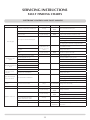
1
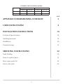
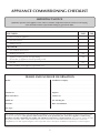
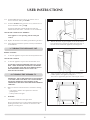
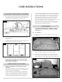
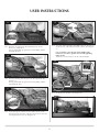
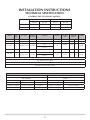
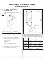
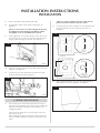
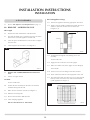
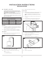
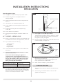
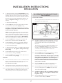
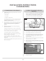
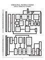
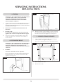
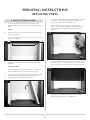
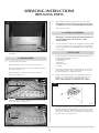
Yeoman CL3 & CL5 Balanced Flue Log Effect Fire Instructions for Use, Installation and Servicing For use in GB, IE (Great Britain and Eire) IMPORTANT THE OUTER CASING, FRONT AND GLASS PANEL BECOME EXTREMELY HOT DURING OPERATION AND WILL RESULT IN SERIOUS INJURY AND BURNS IF TOUCHED. IT IS THEREFORE RECOMMENDED THAT A FIREGUARD COMPLYING WITH BS 8423:2002 IS USED IN THE PRESENCE OF YOUNG CHILDREN, THE ELDERLY OR INFIRM. This product contains a Heat resistant glass panel. This panel should be checked during Installation and at each servicing interval. If any damage is observed on the front face of the glass panel (scratches, scores, cracks or other surface defects), the glass panel must be replaced and the appliance must not be used until a replacement is installed. Under no circumstances should the appliance be used if any damage is observed, the glass panel is removed or broken. This appliance is guaranteed for 2 years (subject to the conditions on page 3 of this Instruction manual). The second year of the guarantee will only be valid if the annual service recommended in this Instruction manual has been completed by a GasSafe registered engineer, and a copy of the service report is available for inspection by a Yeoman engineer. These Instructions must be left with the appliance for future reference and for consultation when servicing the appliance. Please make the customer aware of the correct operation of the appliance before leaving these instructions with them. The commissioning sheet found on Page 3 of this Instruction manual must be completed by the Installer prior to leaving the premises. PR1406 Issue 1 (October 2011) COVERING THE FOLLOWING MODEL: Model Natural Gas LPG Top Exit Rear Exit Top Exit Rear Exit CL3 N/A YM581-374 N/A YM581-539 CL5 YM581-329 YM581-354 YM581-712 YM581-647 PAGE Appliance commissioning checklist 3 user instructions 4 instaLlation Instructions 14 Technical Specifications 14 Site Requirements 16 Installation 20 Commissioning 31 Servicing Instructions 32 Fault Finding 32 How to replace parts 35 Basic spare parts list 42 Service Records 43 2 APPLIANCE COMMISSIONING CHECKLIST IMPORTaNT NOTICE Explain the operation of the appliance to the end user, hand the completed instructions to them for safe keeping, as the information will be required when making any guaranteed claims. FLUE CHECK Pass 1. Flue is correct for appliance 2. Flue flow test N/A 3. Spillage test N/A Fail GAS CHECK 1. Gas soundness & let by test 2. Standing pressure test mb 3. Appliance working pressure (on High Setting) mb NB All other gas appliances must be operating on full 4. Gas rate 5. Does ventilation meet appliance requirements N/A m3/h DEALER AND INSTALLER INFORMATION Dealer . . . . . . . . . . . . . . . . . . . . . . . . . . . . . . . . . . . . . . . . . . . . . . . . . . . . . . . . . . . . . . . . . . . . . Installation Company . . . . . . . . . . . . . . . . . . . . . . . . . . . . . . . . . . . . . . . . . . . . . . . . . . . . . . . . . . . . . . . . . . . . . . . . . . . . . . . . . . . . . . . . . . . . . . . . . . . . . . . . . . . . . . . . . . . . . . . . . . . . . . . . ................................................................................ . . . . . . . . . . . . . . . . . . . . . . . . . . . . . . . . . . . . . . . . . . . . . . . . . . . . . . . . . . . . . . . . . . . . . . . . . . . . . . . ................................................................................ Contact No.. . . . . . . . . . . . . . . . . . . . . . . . . . . . . . . . . . . . . . . . . . . . . . . . . . . . . . . . . . . . . . Engineer . . . . . . . . . . . . . . . . . . . . . . . . . . . . . . . . . . . . . . . . . . . . . . . . . . . . . . . . . . . . . . . . . . . Date of Purchase. . . . . . . . . . . . . . . . . . . . . . . . . . . . . . . . . . . . . . . . . . . . . . . . . . . . . . . Contact No.. . . . . . . . . . . . . . . . . . . . . . . . . . . . . . . . . . . . . . . . . . . . . . . . . . . . . . . . . . . . . . . Model No.. . . . . . . . . . . . . . . . . . . . . . . . . . . . . . . . . . . . . . . . . . . . . . . . . . . . . . . . . . . . . . . . Gas Safe Reg No. . . . . . . . . . . . . . . . . . . . . . . . . . . . . . . . . . . . . . . . . . . . . . . . . . . . . . . . Serial No.. . . . . . . . . . . . . . . . . . . . . . . . . . . . . . . . . . . . . . . . . . . . . . . . . . . . . . . . . . . . . . . . . Date of Installation . . . . . . . . . . . . . . . . . . . . . . . . . . . . . . . . . . . . . . . . . . . . . . . . . . . . Gas Type. . . . . . . . . . . . . . . . . . . . . . . . . . . . . . . . . . . . . . . . . . . . . . . . . . . . . . . . . . . . . . . . . . This product is guaranteed for 2 years from the date of installation, as set out in the terms and conditions of sale between Yeoman and your local Yeoman dealer. This guarantee will be invalid, to the extent permitted by law, if the above Appliance Commissioning Checklist is not fully completed by the installer and available for inspection by a Yeoman engineer. The guarantee will only be valid during the second year, to the extent permitted by law, if the annual service recommended in the Instructions for Use has been completed by a Gas Safe registered engineer, and a copy of the service visit report is available for inspection by a Yeoman engineer. 3 USER INSTRUCTIONS 1.10 This product is guaranteed for 2 years from the date of installation, as set out in the terms and conditions of sale between Yeoman and your local Yeoman dealer. Please consult with your local Yeoman dealer if you have any questions. In all correspondence always quote the Model Number and Serial Number. 1. general In the event of a gas escape or if you can smell gas, please take the following steps: • • • • • • Immediately turn off the gas supply at the meter/ emergency control valve Extinguish all sources of ignition Do not smoke Do not operate any electrical light or power switches (On or Off) Ventilate the building(s) by opening doors and windows Ensure access to the premises can be made The gas supply must not be used until remedial action has been taken to correct the defect and the installation has been recommissioned by a competent person. 1.1 Installation and servicing must only be carried out by a competent person whose name appears on the Gas Safe register. To ensure the engineer is registered with Gas Safe they should possess an ID Card carrying the following logo: Do not place curtains above the appliance: You must have 300mm (1’) clearance between the appliance and any curtains at either side. 1.4 No furnishings or other objects should be placed within 1 metre of the front of the appliance. 1.5 If any cracks appear in the glass panel do not use the appliance until the panel has been replaced. 1.6 In the unlikely event the appliance is receiving interference from other electronic devices, the handset/Control box can be reprogrammed. Please consult your dealer if you think this may be the case. 1.7 If, for any reason, the flue has to be removed from the appliance, the seals must be replaced in the inner spigot. 1.8 Do not obstruct the flue terminal in any way i.e. by planting flowers, trees shrubs etc. in the near vicinity, or by leaning objects up against the terminal guard. IMPORTANT - THE CONTROL SYSTEM HAS BEEN PROGRAMMED TO OPERATE ON CHANNEL 'A'. IN SOME INSTANCES MULTIPLE HOUSEHOLD APPLIANCES MAY HAVE ALSO BEEN SET TO OPERATE ON THE SAME CHANNEL. ALTHOUGH THIS HAS NO EFFECT ON THE SAFETY OF THE SYSTEM YOU MAY ENCOUNTER AN EXCESSIVE DELAY BETWEEN COMMANDS. IF THIS OCCURS PLEASE FOLLOW THE INSTRUCTIONS IN INSTALLATION INSTRUCTIONS, COMMISSIONING, SECTION 3 TO CHANGE THE CHANNEL. The remote control handset has been factory set to only communicate with the appliance it is supplied with. The appliance will not respond to any other remote control, even one from an identical appliance. Note: In the event of a replacement handset being acquired, pairing of the handset with the appliance will need to be carried out. Please refer to Commissioning, Section 2, Pairing Handset on page 29. In all correspondence, please quote the appliance type and serial number, which can be found on the data badge located on a plate attached to the lower slotted trim. 1.3 1.9 Please report the incident immediately to the National Gas Emergency Service Call Centre on 0800 111 999 (England, Scotland and Wales) , 0800 002 001 (N. Ireland) or in the case of LPG, the gas supplier whose details can be found on the bulk storage vessel or cylinder. 1.2 2A. operating the appliance The appliance can be operated in two ways: — Using the remote control handset. — Using the touch pad control on the appliance. The appliance has four flame settings which can be controlled manually or automatically via temperature sensing: 1. High (Pilot lit and main burner lit at the highest flame setting). 2.Med (Pilot lit and main burner lit at the medium flame setting). 3. Low (Pilot lit and main burner lit at the minimum flame setting). 4. Standby (Pilot only). 1 Down Button Up Button On/Off Button AR2516a Do not use a garden sprinkler or hose near the terminal. 4 USER INSTRUCTIONS 2.1 To light the appliance using the remote handset press the On/Off (�) button followed directly by the OK button. The appliance will emit a beep to confirm the order has been received and the LED on the handset will briefly illuminate. After the start up cycle has completed the appliance will light on the high flame setting (this can take up to 20 seconds). To decrease the flame height: 2.2 From the high flame setting press the DOWN () button once to lower the flame to the medium setting. Each time a command from the handset is received by the appliance a beep will be emitted and the LED on the handset will briefly illuminate. NOTE: In normal operating mode the LED on the remote control will flash approximately every 4 seconds to show that it is in communication with the appliance. After each command has been accepted the LED will cease flashing until the command has been carried out. Wait until the LED resumes flashing before giving another command. 2.3 2B. OPERATING THE APPLIANCE TOUCH PAD CONTROL TOUCH PAD CONTROL The touch pad control is located at the base of the front of the appliance (see Diagram 2). 2 Touch pad AR2698 From the medium flame setting press the DOWN () button once to lower the flame to the low setting. 2.4 From the low flame setting press the DOWN () button once to put the appliance in Standby mode (Pilot only). 2.11 To light the appliance press the On/Off button once. The appliance will emit a beep to confirm the order has been received and the LED on the touch pad will briefly illuminate. To increase the flame height: 2.5 To light the appliance when it is in Standby mode press the UP () button once. The appliance will light on the high flame setting. After the start up cycle has completed the appliance will light on the high flame setting (this can take up to 20 seconds). A second beep and flash of the touch pad LED will confirm the command has been carried out. 2.6 From the low setting press the UP () button once to increase the flame setting to medium. To decrease the flame height: 2.7 2.12 From the high flame setting press the DOWN () button once to lower the flame to the medium setting. From the medium setting press the UP () button once to increase the flame setting to high. BATTERIES 2.8 2.9 The remote handset contains 2 x AA 1.5v alkaline batteries. Replace exhausted batteries like for like (use high quality batteries, Duracell or similar). DO NOT USE RECHARGEABLE BATTERIES. Each time a command from the touch pad is received by the appliance a beep will be emitted and the LED on the touch pad will briefly illuminate. A second beep and flash of the touch pad LED will confirm the command has been carried out. Wait for this confirmation before giving another command. 2.13 From the medium flame setting press the DOWN () button once to lower the flame to the low setting. Communication between the handset and the appliance may take up to 2 mins after batteries have been replaced. 2.14 From the low flame setting press the DOWN () button once to put the appliance in Standby mode (Pilot only). 2.10 If communication is not regained after this time the control unit and the handset may need pairing. Please refer to Commissioning, Section 2, Pairing Handset on page 29. To increase the flame height: 2.15 To light the appliance when it is in Standby mode press the UP (w) button once. The appliance will light on the high flame setting. 5 USER INSTRUCTIONS 2.16 From the low setting press the UP (w) button once to increase the flame setting to medium. 3 2.17 From the medium setting press the UP (w) button once to increase the flame setting to high. YELLOW FLAMES WILL APPEAR WHEN THE FIRE HAS GAINED SUFFICIENT HEAT - TYPICALLY 10 TO 20 MINUTES. TOUCH PAD CONTROL NOT WORKING If the appliance is not operating with the touch pad control: AR2694 2.18 Replace the batteries in the battery pack following Section 4. 4.3 2.19 If the appliance still fails to operate consult your installer or Yeoman dealer. 3. turning the APPLIANCE off Remove the frame to gain complete access to the control box and the viewing aperture by lifting the hooks clear of the slots on the front of the appliance, See Diagram 4. 4 REMOTE CONTROL 3.1 To turn the appliance off press the On/Off (�) button once. TOUCH PAD CONTROL 3.2 To turn the appliance off press the On/Off button once. IF THE FIRE IS EXTINGUISHED OR GOES OUT IN USE, WAIT 3 MINUTES BEFORE ATTEMPTING TO RELIGHT IT. THE CONTROL VALVE HAS AN INTERLOCK DEVICE AND THEREFORE CANNOT BE LIT UNTIL THE 3 MINUTES HAVE ELAPSED. AR2693 4.4 4. CLEANING the Yeoman CL Using screwdriver remove the eight screws securing the window panel to the appliance, Diagram 5. Take care to support the glass when removing the screws. 4.1 IMPORTANT: THE OUTER PANELLING OF THE Yeoman CL IS MADE FROM CAST IRON. USE CAUTION when installing, removing and storing as the components are HEAVY and Should be handled carefully. Make sure the fire and surrounds are cool before cleaning. Use: – A dry cloth or stainless steel product to clean the polished plate. – A damp cloth for the glass. 4.2 All Models Unscrew the handle from the upper door. Remove the plinth to access the touchpad and battery box by lifting the hooks clear of the slots on the front of the appliance, See Diagram 3. 5 AR2697 6 USER INSTRUCTIONS minimum, during installation and servicing a HEPA filtered vacuum is recommended to remove any dust accumulated in and around the appliance before and after working on it. When servicing the appliance it is recommended that the replaced items are not broken up, but are sealed within heavy duty polythene bags and labelled as RCF waste. RCF waste is classed as stable, non-reactive hazardous waste and may be disposed of at a licensed landfill site. Excessive exposure to these materials may cause temporary irritation to eyes, skin and respiratory tract; wash hands thoroughly after handling the material. 5. CHANGING THE Yeoman CL BATTERIES 5.1 The appliance batteries are located to the left hand side of the touch pad. This is behind the lower panel, Diagram 6. To remove the panel lift slightly and pull forward. 6 7. LOG LAYOUT LOGS MUST BE POSITIONED ACCORDING TO THE FOLLOWING INSTRUCTIONS TO GIVE THE CORRECT FLAME EFFECT 7A. CL3 Layout Battery holder rests under bracket 7a.1 Ensure the burner tray is clean and free from any debris, Diagram 8. AR2698 5.2 Slide the lid off the top of the battery holder and remove the old batteries. 5.3 Correctly position the three new C Cell size batteries into the battery holder as shown in Diagram 7. 8 7 AR2103 7a.2 Place the rear log into position as illustrated in Diagram 9. Ensure that the left hand edge butts up against the raised groove in the burner tray and the back panel- see Detail A. AR1488a Refit the lid of the battery box and replace into position. PLEASE ENSURE NO WIRES ARE TRAPPED BEFORE REPLACING THE lower panel. THE TOUCH PAD LEAD IS EASILY DAMAGED The three logs that make up the fuel bed are visually distinct and fit into specific parts on the burner tray. 9 6. ARRANGEMENT OF FUEL BED 6.1 Log 1 ADVICE ON HANDLING AND DISPOSAL OF FIRE CERAMICS The fuel effect of the log version of this appliance is made from Refractory Ceramic Fibre (RCF), a material which is commonly used for this application. Protective clothing is not required when handling these articles, but we recommend you follow normal hygiene rules of not smoking, eating or drinking in the work area and always wash your hands before eating or drinking. To ensure that the release of RCF fibres are kept to a Detail A 7 AR2103 USER INSTRUCTIONS 7a.3 Place the second log into the left hand groove on the burner tray and ensure it is pushed as far into the centre as the groove will allow, Diagram 10. 12 10 Embaglow Log 2 AR2103 7a.6 Fix log bar into position, See Diagram 13. 13 AR2103 7a.4 Place the third log into the groove on the right hand side and ensure it is pushed as far into the centre as the groove will allow, Diagram 11. 11 AR2103 7B. CL5 Layout 7b.1 Ensure the burner tray is clean and free from any debris, Diagram 14. 14 Log 3 AR2103 7a.5 Once the logs are in place use some of the Embaglow wire wool provided and cover the ports in the burner tray with a liberal amount of fibres, See Diagram 12. NOTE: It is not necessary to use all of the Embaglow. AR2103 The three logs that make up the fuel bed are visually distinct and fit into specific parts on the burner tray. 7b.2 Place the rear log into position between the rear brackets and pushed up against the back panel as illustrated in Diagram 15. 8 USER INSTRUCTIONS 15 18 Embers Log 1 AR2103 AR2103 7b.6 Use some of the Embaglow provided and cover the ports in the burner tray with a liberal amount of fibres, See Diagram 19. 7b.3 Place the second log into the left hand groove on the burner tray, Diagram 16. The log should butt up against the raised molding and the left hand side liner. It is essential to cover the port in the middle of the burner tray in order to get the most visually appealing flame picture. NOTE: It is not necessary to use all of the Embaglow. 16 19 Log 2 Embaglow AR2103 7b.4 Place the third log into the groove on the right hand side, Diagram 17. The log should butt up against the raised molding and the right hand side liner. It is essential to cover the central port 17 AR2103 7b.7 Fix log bar into position, See Diagram 20. 20 Log 3 AR2103 7b.5 Once the logs are in there are two embers which can be loosely placed at the front of the fire bed and cover the tabs securing the burner tray, See Diagram 18. AR2103 9 USER INSTRUCTIONS 8. flame failure device 8.1 This is a safety feature incorporated on this appliance which automatically switches off the gas supply if the pilot goes out and fails to heat the thermocouple. 9. running in 9.1 The surface coating on the metal used in your Yeoman fire will "burn off" during the first few hours of use producing a harmless and temporary odour. This will disappear after a short period of use. If the odour persists, ask your installer for advice. 9.2 During the first few hours of burning there may be discolouration of the flames. This will also disappear after a short period of use. 10. servicing 10.1 The fire must be serviced every 12 months by a qualified Gas Engineer. In all correspondence always quote the Model number and the Serial number which may be found on the data badge. 11. ventilation 11.1 This appliance requires no additional ventilation. 12. installation details 12.1 Your installer should have completed the commissioning sheet at the front of this book. This records the essential installation details of the appliance. In all correspondence always quote the Model number and Serial number. 13. HOT SURFACES 13.1 Parts of this appliance become hot during normal use. Regard all parts of the appliance as a ‘working surface’. 13.2 Provide a suitable fire guard to protect young children and the infirm. 14. FIRE WILL NOT LIGHT 14.1 If you cannot light the Yeoman CL: – Check and change the batteries in the remote handset. – Check and change the appliance batteries, Section 4. Consult your Yeoman dealer if the Riva still does not light. 10 INSTALLATION INSTRUCTIONS TECHNICAL SPECIFICATION COVERING THE FOLLOWING MODELS: Model Natural Gas Top Exit Rear Exit Top Exit Rear Exit CL3 N/A YM581-374 N/A YM581-539 CL5 YM581-329 YM581-354 YM581-712 YM581-647 Model Gas CAT. CL3 BF I2H Natural (G20) 20mbar I3P Propane (G31) 37mbar I2H Natural (G20) 20mbar I3P Propane (G31) 37mbar CL3 BF CL5 BF CL5 BF LPG Gas Type Working Pressure Aeration Injector 6x6 0.304 3.2 2 0.120 3.2 2 158 0.409 4.3 2.5 GB, IE 110 0.162 4.3 2.5 GB, IE 90 16 x 23 16 x 23 Country Low 6x6 6 x 10 Input kW (Gross) High 185 6 x 10 Gas Rate m3/h GB, IE GB, IE Efficiency Class 2 - 81% / NOx Class 4 Flue Outlet Size Ø 150mm Flue Inlet Size Ø 100mm Gas Inlet Connection Size Ø 8mm RESTRICTOR REQUIREMENT VERTICAL & HORIZONTAL FLUE TOP EXIT - VERTICAL ONLY INCLUDING OFFSET CL3 & CL5 BF CL5 BF Vertical Flue Height Horizontal Length Restrictor Size Vertical Flue Height Restrictor Size 500mm - 990mm 250mm - 1000mm No restrictor 3000 - 4990mm Ø 52mm (Sliding) 1000mm - 1990mm 250mm - 1000mm Ø 60mm 5000mm - 10,000mm Ø 40mm (Sliding) 2000mm - 3000mm 250mm - 1000mm Ø 52mm 11 INSTALLATION INSTRUCTIONS TECHNICAL SPECIFICATION This appliance has been certified for use in countries other than those stated. To install this appliance in these countries, it is essential to obtain the translated instructions and in some cases the appliance will require modification. Contact Yeoman for further information. PACKING CHECKLIST Qty Description Fixing Kit containing:- For Log Layout 1 Log Set 1 Packet of Embaglow 1 2 2 1 3 2 2 2 1 2 1 1 1 x Instruction Manual x Wood Screws x Rawl Plugs x Handset x C cell batteries x AA batteries x Self Tapping Screws x Wingnuts x Fixing Plate x Washers X 40mm Ø Flue Restrictor (CL5 Vertical Flue only) x 52mm Ø Flue Restrictor (CL5 Up & Out Flue only) x 60mm Ø Flue Restrictor (CL5 Up & Out Flue only) CL3 CL5 AR2690 12 INSTALLATION INSTRUCTIONS SITE REQUIREMENTS 1.5 Two types of flue terminals are available, horizontal and vertical. To measure for a horizontal terminal: – Decide on the terminal position. – Measure the height from the top of the appliance to the centre of the required outlet. For minimum and maximum flue dimensions see Diagram 1A / 1B. Allow enough room either above or to the side of the appliance to assemble the flue on top. Assemble a horizontal flue in the following order: - Vertical section - 90° elbow - Horizontal plus terminal 1. Flue and Chimney Requirements Note: This appliance must only be installed with the flue supplied. You must adhere to the following: 1.1 The flue must be sited in accordance with BS5440: Part 1 (latest edition). See Diagram 1. 1.2 Fit a guard to protect people from any terminal less than 2 metres above any access such as level ground, a balcony or above a flat roof. 1.3 All vertical and horizontal flues must be securely fixed and fire precautions followed in accordance with local and national codes of practice. 1.4 A restrictor may be required. Refer to Technical Specifications on page 11. 1 UK Dimensions 13 Support the opening of a masonry installation with a lintel. 1.6 Only the horizontal terminal section can be reduced in size. INSTALLATION INSTRUCTIONS SITE REQUIREMENTS 3 2. REAR FLUE 2.1 REAR FLUE KIT Yeoman CL BF (8526) 2 200mm min 550mm max AR1619 AR0630a Terminal dimensions: 395 x 200 x 200 mm (H x W x D) Guard supplied Cut to length as required on site (see Diagram 2). There are two types of flue terminal: horizontal (Section 3B) and vertical (Section 3D). 3A. TOP FLUE UP AND OUT KIT (8523/8523AN) 3.1 This flue rises vertically from the top of the appliance, then continues horizontally outward (see Diagram 3). The basic kit comprises: 1 1 1 1 1 1 x x x x x x This kit provides the minimum materials. Extra lengths can be added to the vertical and horizontal sections; refer to Section 4. 3.3 Refer to Installation Instructions, Technical Specification (page 14) to identify when to use a restrictor. 3B. For horizontal terminal installations: 3. TOP EXIT FLUES (MIDI ONLY) 3.2 500mm vertical length 500mm terminal length 90 degree elbow wall plate 75mm restrictor fixing screw 3.4 Decide on the terminal position. 3.5 Measure the height from the top of the appliance to the centre of the required hole. For minimum and maximum dimensions see Diagram 3. 3.6 To fit the flue you must have access to the top or the side of the appliance to connect the flue. 3.7 Assemble the vertical sections making sure the top plate and flue collar are fitted before the fluepipe. 3.8 Add the 90° elbow. 3.9 Add the horizontal section and terminal. Only the horizontal part can be reduced in size. 3.10 A masonry installation requires the addition of a suitable lintel to support the opening. Refer to Installation Instructions, Technical Information for details of the flue length. 14 INSTALLATION INSTRUCTIONS SITE REQUIREMENTS 3C. TOP FLUE UP AND OUT WITH ADDITIONAL BEND 5 3.11 An additional bend can be used on the horizontal section (45° or 90°) but the overall horizontal flue is reduced (see Diagram 4). 4 C Either 45° or 90° 90° 10.0m MAX B A 0.5m MIN 0.25m 2.5m When A = 1.0 to 1.499 metres B+C = 1.0 metre max (No restrictor) When A = 1.499 to 3.0 metres B+C = 4.0 metres max (75mm diameter restrictor) 3.0m MIN AR1300 AR1299 3D TOP FLUE VERTICAL OFFSET KIT (999-539/999-539AN) 4. OPTIONAL EXTRA FLUE LENGTHS AND BENDS 3.12 This flue is vertical from the top of the appliance (see Diagram 5). A minimum vertical rise of 3m (9’10”) to a maximum of 10m (32’10”). Nominal Length Actual Length Stainless Finish Anthracite Finish 200mm 140mm 8527 8527AN The basic kit comprises: 2 x 1m lengths 1 x 1m terminal lengths 1 x 52mm restrictor (sliding plate assembly) 1 x 47mm restrictor (sliding plate assembly) 500mm 440mm 8528 8528AN 1000mm 940mm 8529 8529AN 3.13 Extra lengths can be added (see Diagram 5). 45° Bend N/A 8507 8507AN 3.14 Refer to Installation Instructions, Technical Specification (page 9) to identify when to use a restrictor. 90° Bend N/A 8508 8508AN Optional Flue Collar 15 8548MB INSTALLATION INSTRUCTIONS SITE REQUIREMENTS 1 5. GAS SUPPLY This appliance is intended for use on a gas installation with a governed meter. 5.1 Before installation, ensure that the local distribution conditions (identification of the type of gas and pressure) and the adjustment of the appliance are compatible. 5.2 Ensure the gas supply delivers the required amount of gas and is in accordance with the rules in force. 5.3 You can use soft copper tubing on the installation and soft soldered joints outside the appliance and below the fire. Once the position of the appliance has been decided: Follow the instructions for securing the appliance on Page 18. 5.4 A factory fitted isolation device is part of the inlet connection; no further isolation device is required. 7.4 The non-combustible hearth must be at least 12mm thick, and project a minimum of 50mm from the base of the appliance in all directions. 7.5 The appliance is not suitable for installation against a combustible wall. A combustible side wall must be a minimum of 150mm from the appliance. 7.6 This appliance can be installed with an up and out flue (vertical wall - horizontal flue) or with a vertical flue with roof termination (see Flue Options, Section 2 Site Requirements). 5.5 All supply gas pipes must be purged of any debris that may have entered prior to connection to the appliance. 5.6 The gas supply enters through the rear of the LEFT-HAND side of the outer box: AR1894 5.7 The gas supply must be installed in a way that does not restrict the removal of the appliance for servicing and inspection. 6. VENTILATION 6.1 Hearth Installation 7.7 This appliance requires no additional ventilation. 7. APPLIANCE LOCATION 7.1 6 This appliance has been designed to stand on either a hearth or an optional bench: RVACLB100B - Riva Bench Low (100cm wide) RVACB100B - Riva Bench (100cm wide) RVACLB120B - Riva Bench Low (120cm wide) RVACB120B - Riva Bench (120cm wide) RVACLB140B - Riva Bench Low (140cm wide) RVACB140B - Riva Bench (140cm wide) 7.2 To Install the Bench: Follow Section 1 Installation - All Models in Installation guide PM205 supplied with the bench kit. 7.3 To secure the appliance to the bench: You must consider where you place the appliance on the bench before drilling the bench. Diagram 1. This appliance must stand on a non-combustible hearth that is at least 12mm thick and projects 50mm minimum from the base of the appliance in all directions (see Diagram 6). B C Dimensions A Small Midi A 470mm 515mm B 390mm 410mm C 12mm 12mm AR0604 MINIMUM CLEARANCE 16 7.8 The appliance is not suitable for installation against a combustible wall. All combustible materials must be removed from behind the appliance. 7.9 Ensure that all minimum clearances to combustible materials are complied with as shown in Diagrams 7 & 8. INSTALLATION INSTRUCTIONS SITE REQUIREMENTS The specified clearances provide the minimum distance to combustible materials. If the appliance is intended to be installed into a non-combustible opening the clearance to the sides and above the appliance can be reduced. However, it is recommended that the specified clearances are maintained irrespective of the materials used in the construction of the opening to allow adequate air flow and access to controls. The clearance at the rear of the appliance must always be a minimum of 50mm. 225 7 150 150 AR2483a 8 150mm 50mm AR0531a 17 INSTALLATION INSTRUCTIONS INSTALLATION IMPORTANT: REFER TO DATA BADGE AND TECHNICAL SPECIFICATION AT THE FRONT OF THE MANUAL TO ENSURE THE APPLIANCE IS CORRECTLY ADJUSTED FOR THE GAS TYPE AND CATEGORY APPLICABLE IN THE COUNTRY OF USE. FOR DETAILS OF CHANGING BETWEEN GAS TYPES REFER TO SECTION 16, SERVICING, ‘REPLACING PARTS’. 1 1. SAFETY PRECAUTIONS 1.1 For your own and other’s safety, you must install this appliance according to local and national codes of practice. Failure to install the stove correctly could lead to prosecution. Read these instructions before installing and using this appliance. 1.2 These instructions must be left intact with the user. 1.3 Do not attempt to burn rubbish on this appliance. 1.4 Keep all plastic bags away from young children. 1.5 Do not place any object on or near to the appliance and allow adequate clearance above the appliance. IF THE APPLIANCE IS EXTINGUISHED OR GOES OUT IN USE, WAIT 3 MINUTES BEFORE ATTEMPTING TO RELIGHT THE APPLIANCE. AR2694 2.3 Remove the frame to gain complete access to the control box and the viewing aperture by lifting the hooks clear of the slots on the front of the appliance, See Diagram 2. 2 2. installation of the appliance AR2693 IMPORTANT: THE OUTER PANELLING OF THE Yeoman CL IS MADE FROM CAST IRON. USE CAUTION when installing, removing and storing as the components are HEAVY and Should be handled carefully. 2.1 Remove the appliance from the carton and discard all unnecessary packaging ensuring no components are thrown away when unpacking. The cast lid is stored on top of the appliance. Remove and store in a safe place. 2.2 All Models Remove the plinth to access the touchpad and battery box by lifting the hooks clear of the slots on the front of the appliance, See Diagram 1. SECURING The Appliance The appliance sits on a mounting bracket to secure it in place to either the hearth or bench. 2.4 Position the appliance: Loosely attach the bracket to the appliance and place centrally on the hearth OR in the desired position on the bench. Remove the appliance leaving the bracket in the correct position and mark the holes to drill the bracket screws, Diagram 3. 3 Brackets AR2458 18 INSTALLATION INSTRUCTIONS INSTALLATION 2.5 Remove the bracket and drill the guide holes. 2.6 Fix the bracket either to the hearth or the bench, see Diagram 3. NOTE: For Top Exit appliances the flue collar must be placed on the flue exit before the top is fitted. 3.2 NOTE: Use the wood screws and rawl plugs in the fixing kit supplied for hearth mounting installations and the self tapping screws for installation onto a bench. To fit the top line up the raised fins on the underside of the glass plate with the cut outs in the top of the box, see Diagram 6. 2.7 6 Rear Exit Lift the appliance so as to locate the key slots in the carcass onto the fixing screws. There are two large holes the lower flanges on the front edges of the base, see Diagram 4. 4 Fins Cut Outs AR2692 Key slots AR2703 Top Exit Wingnut Washer AR2688 2.8 Place the two large washers over the studs and fix with two wingnuts, see Diagram 4. 2.9 Connect the gas to the 8mm elbow located on the right hand side under the firebox, Diagram 5. Fins Cut Outs Offset edge to rear AR2696 5 3.2 When properly fitted the rear of the glass plate should sit flush with the rear of the appliance, see Diagram 7. 7 AR2698 3. Fitting the top plate 3.1 The Yeoman CL has a decorative plate that sits on top of the outer box. Depending on the choice of flue exit this top will have a hole for the flue pipe to pass through or be completely smooth. AR2695 The hole will be situated in an off set position to the rear edge of the cast top. When installing the spigot must be put in place before the cast top is located. Then the connection to the flue can be made. 19 INSTALLATION INSTRUCTIONS INSTALLATION Flue and Appliance Fixings 4. FLUE ASSEMBLY 4.1 4.13 Position the appliance observing appropriate clearances. Refer to Flue Options in Site Requirements on page 13. 4.14 Apply a bead of suitable weatherproof sealant (silicone or similar) to perimeter of back face of terminal (see Diagram 6, A). 4A. Rear EXIT - Horizontal flue Flue Length 6 4.2 Measure the total wall thickness and add 65mm. 4.3 The total flue length gives a minimum clearance of 50mm between the rear of the appliance and the wall. 4.4 4.5 A Insert the square cardboard sleeve into the flue to support the inner tube. Cut through the flue and sleeve (see Diagram 5). 5 AR0606 4.15 Feed the flue through the wall, making sure it runs smoothly. On the inside wall: 4.16 Engage the flue in the inner and outer spigots. 4.17 Make sure rubber seals on the spigots are not damaged From outside: AR0630a 4.6 4.7 4.18 Insert four screws in the flanges of the flue terminal. REMOVE THE CARDBOARD REMNANTS FROM THE FLUE. 4.18 Check sealant has formed a water-tight joint to the wall. File the cut edges smooth. 4.19 Any terminal less than 2m above any access (level ground, balcony or flat roof with access) must be fitted with the guard supplied (see Diagram 7). Terminal On the outside wall: 4.8 Position the flue assembly into the hole. The terminal should be flat against the wall. 4.9 Make sure the terminal is vertical (see Diagram 5). 7 4.10 Mark the four fixing holes. 4.11 Remove the terminal to drill the holes. 4.12 Insert wall plugs supplied. DO NOT FIX THE FLUE AT THIS STAGE. AR0603 20 INSTALLATION INSTRUCTIONS INSTALLATION 4B TOP EXIT - UP & OUT 4.25 Make good at both ends of the hole. Flue Length ENSURE THE BLACK DECORATIVE top and COLLAR ARE FITTED TO THE TOP OF THE APPLIANCE PRIOR TO installation OF A TOP FLUE EXIT. THIS MUST BE POSITIONED BEFORE INSTALLING THE FLUE. 4.26 The final length of the flue pipe includes the terminal. The terminal is the only section that can be shortened. A restrictor may be required with top exit flues. See chart below for restrictor sizes. DO NOT SHORTEN ANY OTHER SECTION OF FLUE PIPE. 4.27 Measure from the outside of the wall to the stop on the 90° elbow. VERTICAL & HORIZONTAL FLUE 4.28 Fit horizontal flue section between the elbow and the terminal at this stage, if required (see Diagram10). Riva Vision Small & Midi BF Vertical Flue Height Horizontal Length Restrictor Size 500mm - 990mm 250mm - 1000mm No restrictor 1000mm - 1990mm 250mm - 1000mm Ø 60mm 2000mm - 3000mm 250mm - 1000mm Ø 52mm 10 Wall plate 10mm Wall Plate 4.20 A wall plate is supplied to secure the flue to the inside wall. Bend the securing tab to 90° and slot the plate over the flue before bringing the flue through the wall. 4.21 Mark the fixing holes using the wall plate as a template The tab can be above or beneath the flue (see Diagram 10). AR0629 Flue Aperture 4.29 Mark the correct length all the way around the flue terminal section (see Diagram 10). 4.22 Mark the height from the top of the hearth to the centre of the horizontal section (see Diagram 9). 4.30 Insert the square cardboard sleeve into the flue to support the inner tube. 9 4.31 Cut through the flue and sleeve (see Diagram 11). 11 AR0630 AR0628 4.23 TAKE CARE TO MARK OUT THE FLUE CORRECTLY. IT IS DIFFICULT TO MOVE AFTER INSTALLATION. 4.32 REMOVE THE CARDBOARD REMNANTS FROM THE FLUE. 4.24 Create a 152mm (6”) diameter hole for the flue using either: a) a core drill, or b) a hammer and chisel 4.33 File the cut edge smooth. 21 INSTALLATION INSTRUCTIONS INSTALLATION Flue and Appliance Fixings 12 4.34 Pull appliance and flue assembly away from the hearth. 4.35 Drill four fixing holes for the wall plate and insert wall plugs supplied. Restrictor assembly 4.36 Put the horizontal flue onto the elbow and reposition the appliance. 4.37 Check the flue runs smoothly through the wall. 4.38 Fix the wall plate to the wall using the four black screws provided. Slide collars 4.39 Drill through the fixing tab of the wall plate using a 3.5mm drill. AR2396 4.40 Secure with the screw provided. 4.47 Flue Lengths over 5m (Midi Top Exit Only) 4.41 Make good and weatherproof around the outside of the flue. 4C. TOP EXIT – VERTICAL FLUE 4.42 Where a vertical only flue system has been purchased, refer to Installation & Instructions, Site Requirements, Section 3D. If the flue length extends 5m above the appliance a 40mm Ø restrictor must be fitted. This restrictor can be found in the appliance packing kit supplied. 4.48 To fit the restrictor undo the bolts on the slide collars on the restrictor assembly, see Diagram 13. 4.43 Pay careful attention to the following: 13 Terminal positions Flue supports Weatherproofing Fire precautions Screws 4.44 Local and national codes of practice must be followed for all the above. Restrictor plate 4.45 A restrictor must be fitted with vertical flues. See chart below for restrictor sizes. Please note: When installing the appliance in conjunction with a vertical termination kit, there is a unique kit for use with this appliance (Yeoman Part No. 999-539). This kit differs in that it has restrictors with sliding plates. Please ensure you have the correct kit before proceeding with the installation. Vertical Height from Appliance Restrictor Size 3000mm to 4990mm 52mm ø (Sliding) 5000mm to 10000mm 40mm ø (Sliding) AR2396a 4.49 Remove the restrictor plate that is current in place and fit the 40mm Ø one from the kit. Secure with the screws and ensure that the plate moves freely up and down on the slide collars. 4.50 Fit the restrictor assembly as previous described. PURGE THE SUPPLY PIPE 4.46 It is important that the sliding restrictor assembly is used. The restrictor assembly must be fitted with the slide collars uppermost and the top restrictor plate must be checked to ensure it moves freely before the flue is fitted. This is essential to expel any debris that may block the gas controls. 4.51 Connect the gas to the 8mm elbow on the rear of the appliance, See Diagram 14. 22 INSTALLATION INSTRUCTIONS INSTALLATION 14 6. LOG LAYOUT LOGS MUST BE POSITIONED ACCORDING TO THE FOLLOWING INSTRUCTIONS TO GIVE THE CORRECT FLAME EFFECT Small Vision Layout 6a.1 Ensure the burner tray is clean and free from any debris, Diagram 15. AR2698 15 4.52 Connect a suitable pressure gauge to the test point located on the inlet fitting. Turn on the gas Light the appliance and check for leaks Turn the appliance to maximum and check that the supply pressure is as stated on the data badge. Turn off the gas and replace the test point screw Turn the gas back on and check the test point for leaks AR2103 5. ARRANGEMENT OF FUEL BED 5.1 ADVICE ON HANDLING AND DISPOSAL OF FIRE CERAMICS The fuel effect of the log version of this appliance is made from Refractory Ceramic Fibre (RCF), a material which is commonly used for this application. The three logs that make up the fuel bed are visually distinct and fit into specific parts on the burner tray. 6a.2 Place the rear log into position as illustrated in Diagram 16. Ensure that the left hand edge butts up against the raised groove in the burner tray and the back panel- see Detail A. 16 Protective clothing is not required when handling these articles, but we recommend you follow normal hygiene rules of not smoking, eating or drinking in the work area and always wash your hands before eating or drinking. To ensure that the release of RCF fibres are kept to a minimum, during installation and servicing a HEPA filtered vacuum is recommended to remove any dust accumulated in and around the appliance before and after working on it. When servicing the appliance it is recommended that the replaced items are not broken up, but are sealed within heavy duty polythene bags and labelled as RCF waste. RCF waste is classed as stable, non-reactive hazardous waste and may be disposed of at a licensed landfill site. Excessive exposure to these materials may cause temporary irritation to eyes, skin and respiratory tract; wash hands thoroughly after handling the material. Log 1 Detail A AR2103 6a.3 Place the second log into the left hand groove on the burner tray and ensure it is pushed as far into the centre as the groove will allow, Diagram 17. 23 INSTALLATION INSTRUCTIONS INSTALLATION 19 17 Log 2 Embaglow AR2103 AR2103 6a.6 Fix log bar into position, See Diagram 20. 6a.4 Place the third log into the groove on the right hand side and ensure it is pushed as far into the centre as the groove will allow, Diagram 18. 20 18 AR2103 Midi Vision Layout 6b.1 Ensure the burner tray is clean and free from any debris, Diagram 21. 21 Log 3 AR2103 6a.5 Once the logs are in place use some of the Embaglow wire wool provided and cover the ports in the burner tray with a liberal amount of fibres, See Diagram 19. NOTE: It is not necessary to use all of the Embaglow. AR2103 The three logs that make up the fuel bed are visually distinct and fit into specific parts on the burner tray. 6b.2 Place the rear log into position between the rear brackets and pushed up against the back panel as illustrated in Diagram 22. 24 INSTALLATION INSTRUCTIONS INSTALLATION 25 22 Embers AR2103 Log 1 AR2103 6b.6 Use some of the Embaglow provided and cover the ports in the burner tray with a liberal amount of fibres, See Diagram 26. 6b.3 Place the second log into the left hand groove on the burner tray, Diagram 23. The log should butt up against the raised molding and the left hand side liner. 23 It is essential to cover the port in the middle of the burner tray in order to get the most visually appealing flame picture. NOTE: It is not necessary to use all of the Embaglow. 26 Embaglow Log 2 AR2103 6b.4 Place the third log into the groove on the right hand side, Diagram 24. The log should butt up against the raised molding and the right hand side liner. It is essential to cover the central port 24 AR2103 6b.7 Fix log bar into position, See Diagram 27. 27 Log 3 AR2103 6b.5 Once the logs are in there are two embers which can be loosely placed at the front of the fire bed and cover the tabs securing the burner tray, See Diagram 25. AR2103 25 INSTALLATION INSTRUCTIONS INSTALLATION 7.3 7. COMPLETION OF ASSEMBLY 8. Operating the appliance 7.1 To fit the window frame: Offer the frame to the foot of the opening and secure using 8 screws as shown, Diagram 28. IMPORTANT - THE CONTROL SYSTEM HAS BEEN PROGRAMMED TO OPERATE ON CHANNEL 'A'. IN SOME INSTANCES MULTIPLE HOUSEHOLD APPLIANCES MAY HAVE ALSO BEEN SET TO OPERATE ON THE SAME CHANNEL. ALTHOUGH THIS HAS NO EFFECT ON THE SAFETY OF THE SYSTEM YOU MAY ENCOUNTER AN EXCESSIVE DELAY BETWEEN COMMANDS. IF THIS OCCURS PLEASE FOLLOW THE INSTRUCTIONS IN INSTALLATION INSTRUCTIONS, COMMISSIONING, SECTION 3 TO CHANGE THE CHANNEL. 28 The remote control handset has been factory set to only communicate with the appliance it is supplied with. The appliance will not respond to any other remote control, even one from an identical appliance. Note: In the event of a replacement handset being acquired, pairing of the handset with the appliance will need to be carried out. Please refer to Commissioning, Section 2, Pairing Handset on page 29. AR2697 7.2 Attach the door handle. Fit the front and the plinth by inserting the hooks on the back of the frame into the slots on the front of the appliance, See Diagram 29 & 30. 29 AR2694 30 The appliance can be operated in two ways: — Using the remote control handset. The appliance has four flame settings which can be controlled manually or automatically via temperature sensing: 1. High (Pilot lit and main burner lit at the highest flame setting). 2.Med (Pilot lit and main burner lit at the medium flame setting). 3. Low (Pilot lit and main burner lit at the minimum flame setting). 4. Standby (Pilot only). — Using the touch pad control on the appliance. 31 Down Button Up Button On/Off Button AR2516a AR2693 26 INSTALLATION INSTRUCTIONS INSTALLATION 8.1 To light the appliance using the remote handset press the On/Off button (�) followed directly by the OK button. The appliance will emit a beep to confirm the order has been received and the LED on the handset will briefly illuminate. After the start up cycle has completed the appliance will light on the high flame setting (this can take up to 20 seconds). To decrease the flame height: 8.2 From the high flame setting press the DOWN () button once to lower the flame to the medium setting. Each time a command from the handset is received by the appliance a beep will be emitted and the LED on the handset will briefly illuminate. NOTE: In normal operating mode the LED on the remote control will flash approximately every 4 seconds to show that it is in communication with the appliance. After each command has been accepted the LED will cease flashing until the command has been carried out. Wait until the LED resumes flashing before giving another command. 8.3 8B. OPERATING THE APPLIANCE TOUCH PAD CONTROL TOUCH PAD CONTROL The touch pad control is located at the base of the front of the appliance (see Diagram 232). 32 Touch pad AR2698 From the medium flame setting press the DOWN () button once to lower the flame to the low setting. 8.4 From the low flame setting press the DOWN () button once to put the appliance in Standby mode (Pilot only). 8.11 To light the appliance press the On/Off button once. The appliance will emit a beep to confirm the order has been received and the LED on the touch pad will briefly illuminate. To increase the flame height: 8.5 To light the appliance when it is in Standby mode press the UP () button once. The appliance will light on the high flame setting. After the start up cycle has completed the appliance will light on the high flame setting (this can take up to 20 seconds). A second beep and flash of the touch pad LED will confirm the command has been carried out. 8.6 From the low setting press the UP () button once to increase the flame setting to medium. To decrease the flame height: 8.12 From the high flame setting press the DOWN () button once to lower the flame to the medium setting. 8.7 From the medium setting press the UP () button once to increase the flame setting to high. BATTERIES 8.8 8.9 The remote handset contains 2 x AA 1.5v alkaline batteries. Replace exhausted batteries like for like (use high quality batteries, Duracell or similar). DO NOT USE RECHARGEABLE BATTERIES. Each time a command from the touch pad is received by the appliance a beep will be emitted and the LED on the touch pad will briefly illuminate. A second beep and flash of the touch pad LED will confirm the command has been carried out. Wait for this confirmation before giving another command. 8.13 From the medium flame setting press the DOWN () button once to lower the flame to the low setting. Communication between the handset and the appliance may take up to 2 mins after batteries have been replaced. 8.14 From the low flame setting press the DOWN () button once to put the appliance in Standby mode (Pilot only). 8.10 If communication is not regained after this time the control unit and the handset may need pairing. Please refer to Commissioning, Section 2, Pairing Handset on page 29. To increase the flame height: 8.15 To light the appliance when it is in Standby mode press the UP () button once. The appliance will light on the high flame setting. 8.16 From the low setting press the UP (w) button once to increase the flame setting to medium. 27 INSTALLATION INSTRUCTIONS INSTALLATION 8.17 From the medium setting press the UP (w) button once to increase the flame setting to high. YELLOW FLAMES WILL APPEAR WHEN THE FIRE HAS GAINED SUFFICIENT HEAT - TYPICALLY 10 TO 20 MINUTES. TOUCH PAD CONTROL NOT WORKING If the appliance is not operating with the touch pad control: 8.18 Replace the batteries in the battery pack following Section 4. 8.19 If the appliance still fails to operate consult your installer or Yeoman dealer. 9. turning the APPLIANCE off REMOTE CONTROL 9.1 To turn the appliance off press the On/Off (�) button once. TOUCH PAD CONTROL 9.2 To turn the appliance off press the On/Off button once. IF THE FIRE IS EXTINGUISHED OR GOES OUT IN USE, WAIT 3 MINUTES BEFORE ATTEMPTING TO RELIGHT IT. THE CONTROL VALVE HAS AN INTERLOCK DEVICE AND THEREFORE CANNOT BE LIT UNTIL THE 3 MINUTES HAVE ELAPSED. 28 INSTALLATION INSTRUCTIONS COMMISSIONING 1. COMMISSIONING the appliance 1.1 Complete the Commissioning Checklist at the front of this manual covering: — Flue checks — Gas checks — Log layout - flame picture For working pressure test, use the access panel at the gas connection ensuring the burner is in position. Refer to Installation Instructions, Section 3. 1.2 Upon completion of of the commissioning and testing of the installation and correct operation of the appliance, the installer must instruct the user how to operate the appliance. 1.3 Guide the user through the User Instructions paying particular attention to: a) Regular servicing (Section 10 of the User Instructions). b) Ventilation (Section 11 of the User Instructions) - point out the ventilation positions where applicable. c) Hot surfaces (Section 13 of the User Instructions). d) How the appliance works with the touch pad control (Section 2B of the User Instructions). e) How the appliance works with the remote control handset and the modes of operation (Section 2A of the User Instructions). 2. PAIRING THE HANDSET WITH THE APPLIANCE Prior to re-connection of the control box to the appliance, if there is no communication between the remote handset and the appliance, or if the handset is replaced, it will be necessary to pair the (new) handset with the appliance. 2.1 Remove the 2 x screws securing the control box bracket. 1 Screws AR2698 g) What to do if the appliance fails to operate (Section 14 of the User Instructions). 2.2 Ensure batteries are fitted and working in the handset. 2.3 Ensure all leads and cables are connected correctly. 2.4 Press the On/Off button (�) for at least 10 seconds. The LED will flash on and off as normal during this time. When the LED on the control lights up for at least 1 second release the button. 2.5 Within 5 seconds of the LED going out press the () button followed directly by the () button. 2.6 Within 20 seconds press the yellow button on the control box (see Diagram 2). This may be easier using a pencil, ball point pen or similar. 2 Remote Handset Pairing Button AR2510 2.7 29 The control box will beep to confirm the pairing operation has been successful. INSTALLATION INSTRUCTIONS COMMISSIONING If there are any difficulties achieving pairing ensure that the handset is set to Channel A. To do this follow the steps below: 2.8 Press the On/Off button (�) for at least 10 seconds. The LED will flash on and off as normal during this time. When the LED on the control lights up for at least 1 second release the button. 2.9 Within 5 seconds of the LED going out press the OK button and then press the () button. 2.10 Disconnect the batteries from the control box and reconnect after 10 seconds. The handset will now be set to Channel A. 2.11 Attempt the pairing again following the steps below: NOTE: These steps differ from the previous. 2.12 Press the On/Off button (�) for at least 10 seconds. The LED will flash on and off as normal during this time. When the LED on the control lights up for at least 1 second release the button. 2.13 Within 5 seconds of the LED going out press the () button followed directly by the () button. 2.14 Disconnect the battery pack from the control box and reconnect after 10 seconds. 2.15 The motor on the valve will turn. Once it has stopped repeatedly press and release the yellow button on the control box until the control box beeps to confirm the pairing operation has been successful. 3. CHANGING COMMUNICATION CHANNEL 3.1 Press the On/Off button (�) for at least 10 seconds. The LED will flash on and off as normal during this time. When the LED on the control lights up for at least 1 second release the button. 3.2 Within 5 seconds of the LED going out press the OK button. 3.3 Use the UP () and DOWN () buttons to select a new communication channel. Assuming the appliance is set to Channel A press the UP () button once to select Channel B, and again to select Channel C. From Channel C press the DOWN () button once to select Channel B, and again to select Channel A. 3.4 Once the chosen channel has been selected disconnect the battery pack from the control box and reconnect after 10 seconds. This completes the channel change. 30 3.5 To reset the communication channel to Channel A press the On/Off button (�) for at least 10 seconds. The LED will flash on and off as normal during this time. When the LED on the control lights up for at least 1 second release the button. 3.6 Within 5 seconds of the LED going out press the OK button. Do not give any further commands for at least 10 seconds. 3.7 To return to normal operating mode wait for at least 5 seconds or press the On/Off button (�) once. SERVICING INSTRUCTIONS SERVICING / FAULT FINDING CHARTS 1. SERVICING REQUIREMENTS IMPORTANT – The glass panel on this appliance should be checked for any signs of damage on the front face of the glass panel (scratches, scores, cracks or other surface defects). If damage is observed, the glass panel must be replaced and the appliance must not be used until a replacement is installed. Under no circumstances should the appliance be used if any damage is observed. Please isolate the appliance until a replacement glass panel has been obtained and installed. Replacement glass panels can be purchased from Yeoman via the dealer from which the appliance was purchased or any other Yeoman distributor. 1.1 Before Testing: —Conduct a gas soundness test for the property ensuring there are no leaks before servicing. —Check the operation of the appliance before testing. 1.2 Special checks: —Clean away lint or fluff from the pilot. —Clean away lint or fluff from under the burner. —Check the spark gap on the pilot is correct. 1.3 Correct any faults found during the initial test. 1.4 Re-commission the appliance in accordance with Commissioning Procedures as detailed on page 31 of these instructions. 1.5 Advise the customer of any remedial work undertaken. This appliance must be serviced at least once a year by a competent person. All tests must be carried out in accordance with the current Gas Safe recommendations. 31 No SYSTEM OK GO TO THE NEXT CHART IGNITION FUNCTIONAL CHECK 2 Purge the gas pipes and retry. There is a blockage in the system, check the inlet test point, the mag seating and valve. Check thermocouple leads for correct orientation, condition and connection Has the system got any air in it? Yes Yes Yes Is the gas pressure correct? No Correct and retry. Check isolation tap and gas meter, retry. No Is the gas turned on to the appliance? No Will the pilot light with a match? Yes Check alignment of pilot burner head. Change the ignition lead. See Replacing Parts, section 8. Yes Is the control being operated correctly? No Consult User Instructions and retry. No Does the pilot light? Yes Operate the valve control system in the manual mode via the touch pad or remote. Is there a spark? No Ensure there is no debris around the pilot assembly, (e.g. soot, etc.) which could short the spark, clean the area. PILOT WILL NOT LIGHT IGNITION FUNCTIONAL CHECK 1 Yes REPLACE BATTERIES BEFORE ATTEMPTING TO RECTIFY ANY FAULTS. 32 Replace the lead, retry. No Has the ignition lead become detached from the control box? No Replace the electrode Yes Correct and retry. Check the tab on the pilot burner is not damaged. Either repair tab or replace pilot burner and retry. Is the control system being operated correctly? Check handset batteries are OK. Replace if required. Check handset is on manual. Check if handset lock is off. Check batteries to the control unit. Replace if required. Retry with handset and touch pad. Replace the ignition lead and retry. Yes Yes No No Remove the ignition lead from electrode. With insulated pliers. Hold the tip 4.0mm from the pilot pipe work, is there a spark when the system is operated? No Has ignition lead become detached or is connection poor? Yes Is the gap between electrode and thermocouple 4.0mm? Yes From Ignition Fault Finding Chart 1 Consult the users instructions, retry. Ensure there is no debris around the pilot assembly, (e.g. soot etc.) which could short the spark, clean the area. NO SPARK IGNITION FUNCTIONAL CHECK 2 Yes Change the pilot unit. No Yes Will pilot stay alight? SYSTEM OK Change mag unit. No Will pilot stay alight? No No No Yes Yes Replace pilot unit. No Is thermocouple connection good in back of valve? Problem is with the pipe work or fittings which lead to the appliance. Correct and retry. Yes No No Is the pilot flame of the correct length? Is the thermocouple in its correct position in the pilot bracket. See Replacing Parts, section 8 Yes With the pilot running is the gas pressure as stated on the data badge? Yes Run for 3 mins, turn off, time interval until mag unit shuts with a click. Is this greater than 7 seconds? Tighten the connection and retry. Run for 3 mins, turn off, time interval until mag unit shuts with a click. Is this greater than 7 seconds? Yes With the appliance running on full is the gas at the pressure stated on the data badge? Light the pilot using either the handset or the touch pad Ensure there is no debris around the pilot assembly, (e.g. soot etc.) Check for fluff in the pilot aeration hole. See the Diagram in the Replacing Parts section. PILOT WILL NOT STAY LIT OR FIRE GOES OUT IN USE No Yes Is the flue working? Yes Rectify flue FLAME FAILURE FUNCTIONAL CHECK 3 SERVICING INSTRUCTIONS FAULT FINDING CHARTS SERVICING INSTRUCTIONS FAULT FINDING CHARTS ELECTRONIC CONTROL VALVE FAULT ANALYSIS Problem Cause Error Message LCD Display 10 beeps BATTERY ERROR ROM error 2 cycles of 3 beeps ROM ERROR Support test error 2 cycles of 5 beeps SUPPORT ERROR No batteries or flat batteries in battery box Solution Place new batteries in battery box Change control unit Connect earth cable from control box to valve Change batteries in the remote handset Check the reception of signal from a shorter distance Bad reception of remote handset signal Try pairing again Does not ignite Try changing the channel in the configuration menu No response to touch control buttons Cable loose or broken or connected wrong way round Supply cable to valve disconnected or broken Sparks but no pilot ignition Pilot ignites but does not stay on Ignites from remote handset but not from touch pad Ensure the touch control cable is correctly connected (see installation manual) If LED is continuously on, the cable is connected the wrong way round 2 cycles of 5 beeps Change touch control SUPPORT ERROR Reconnect or replace valve cable Ignition cable disconnected or broken Connect ignition cable Gas valve supply off or no gas Check gas installation. Open gas valve Valve cable disconnected or broken Connect valve cable correctly Pilot cable disconnected or broken Connect correctly or replace pilot cable Pilot is not warmed up Check pilot flame and verify that it heats the pilot Pilot cable badly connected Change polarity of pilot cable Pilot cable disconnected or broken Connect pilot cable Touch control cable disconnected or broken Connect or replace touch control cable Defective touch control buttons Change touch control Check batteries in handset Ignites from touch pad but not from remote Check reception of signal from a shorter distance Bad communication with handset Try pairing again Try changing the channel in the configuration menu Switches off after 6 seconds Short circuit in touch control 5 beeps Low batteries on remote Appliance switches off BUTTON ERROR Low battery 2 cycles of 3 beeps CONFIG ERROR 2 cycles of 3 beeps EEPRON ERROR Loss of communication between appliance and remote for 18min 20 beeps High temperature on control unit 1 long beep Ambient temperature higher than configured 33 Change touch control wiring Change the batteries in the remote Change control unit Try pairing again Change control unit The remote is too far from the appliance Replace batteries in handset TEMP ERROR If this occurs more than once call the technical service Over Temperature Check the correct configuration of safety temperature SERVICING INSTRUCTIONS REPLACING PARTS 2 1. GENERAL IMPORTANT: THE OUTER PANELLING OF THE Yeoman CL IS MADE FROM GLASS. USE CAUTION when installing, removing and storing as the components are fragile and could break unless handled carefully. 1.1 All main components can be replaced without removing the appliance from its installation. It is essential that the gas supply to the appliance is turned off at the isolation device before proceeding further. 1.2 DISCONNECT BATTERIES BEFORE SERVICING THE APPLIANCE 1.3 AR2693 Removal of Flue If, for any reason, the flue has to be removed from the appliance, the seal must be replaced in the inner spigot. 1.4 2.2 Remove the frame to gain complete access to the control box and the viewing aperture by lifting the hooks clear of the slots on the front of the appliance, See Diagram 2. Access to the controls is restricted and the whole of the control assembly is to be removed as one unit. Refer to Section 8 below 3. WINDOW FRAME ASSEMBLY 3.1 2. DECORATIVE FRont Using screwdriver remove the eight screws securing the window panel to the appliance, Diagram 3. Take care to support the glass when removing the screws. IMPORTANT: THE OUTER PANELLING OF THE Yeoman CL IS MADE FROM CAST IRON. USE CAUTION when installing, removing and storing as the components are HEAVY and Should be handled carefully. 2.1 All Models Unscrew the door handle from the upper door. Remove the plinth to access the touchpad and battery box by lifting the hooks clear of the slots on the front of the appliance, See Diagram 1. 3 1 AR1860 AR2694 34 3.2 Place carefully to one side. 3.3 Refit in reverse order. SERVICING INSTRUCTIONS REPLACING PARTS 4. Baffle & CERAMIC LINERS 4.1 To access the burner tray and interior workings of the appliance it may be necessary to remove the baffle and the liners. BAFFLE 4.2 The baffle must be removed before the liners can be taken out of the appliance. To do this undo the two screws securing it to the roof of the firebox, See Diagram 4. 4.5 To remove the Right Hand liner first tilt inwards towards the centre of the firebox before lifting up and pulling out through the front of the firebox, Diagram 15. The two side liners also support the raised rear liner. Taking out the side liners will allow the rear liner to drop down so ensure it is supported and removed carefully, Diagram 16. 16 4 Screws AR2149 AR1865 4.3 The baffle can now be removed through the front of the appliance. CERAMIC LINERS Once the baffle has been placed carefully to one side the liners can then been taken out in the following order. 4.4 To remove the Left Hand liner first tilt inwards towards the centre of the firebox before lifting up and pulling out through the front of the firebox, Diagram 5. 4.6 The lower rear liner does not need to be removed from the bracket in order to access the burner tray for maintenance, but can be lifted off in order to clean or replace, Diagram 17. 17 5 AR2150 4.7 AR2148 35 With the liners and baffle removed the firebox is clear for cleaning and maintenance, See Diagram 18. SERVICING INSTRUCTIONS REPLACING PARTS 18 5.3 Slide the burner fully to the left and out of its location. IMPORTANT: Take care when removing the burner not to damage the ceramic pad with the pilot unit attached. Refit in reverse order 6. CONTROL ASSEMBLY DISCONNECT THE BATTERIES PRIOR TO REMOVAL OF THE ASSEMBLY parts. SEE SECTION 5 USERS INSTRUCTIONS. 6.1 It is not necessary to remove the complete control assembly to service or replace parts of this appliance. The following sections will detail how to individually remove and replace each element. AR2150 4.8 7. PILOT UNIT To replace the liners liner and baffle reverse these procedures. 5. maIN BURNER 5.1 To remove the main burner: Remove the baffle and ceramic liners, see Section 4. Remove the burner bracket screw on the left hand side of the firebox, Diagram 19. Remove the three securing screws from the edges of the burner, Diagram 19. 7.1 Turn the gas supply off at the isolation device, remove the door and place to one side, carefully remove the ceramic fuel bed components including the liners. 7.2 Remove the two fixing screws from the pilot bracket, see Diagram 21. Gently draw the assemble away from the firebox to give access to the nuts and ignition lead. NOTE: TAKE CARE NOT TO DAMAGE THE GASKET. 19 21 Screws Burner Bracket 5.2 The pilot assembly consists of five components, which can be individually changed, these are: 1) Pilot burner bracket 2) Pilot injector 3) Electrode 4) Thermocouple 5) Gasket. AR1868 Slide the burner to the left whilst lifting the Left Hand side clear of the bracket, Diagram 20. AR0614 20 7.4 To remove the pilot injector, undo the compression nut on the pilot feed pipe and withdraw the injector which will be hooked onto the olive. When replacing an injector always make sure it is hooked onto the olive before inserting it into the pilot burner. See Diagram 22. Slide to the left and lift the Left hand side AR1868 36 SERVICING INSTRUCTIONS REPLACING PARTS 8. IGNITION LEAD 22 8.1 Gain access to the back of the pilot assembly, see Section 7 above and disconnect the ignition lead from the electrode. 8.2 Cut the cable tie securing the vida flex (if present) and pull the lead through the vida flex. 8.3 If necessary cut any cable ties and disconnect the lead from the control box (see Diagram 25). 25 26 AR1604 Ignition lead connection 7.5 To remove the electrode, disconnect the ignition lead and undo the retaining nut. The electrode can now be removed, note the orientation of the electrode terminal when reassembling. See Diagram 23. 23 AR2506a 8.4 8.5 AR0616 Replace in reverse order. Ensure the lead is passed through the vida flex, secured with a cable tie and the red insulated end is attached to the electrode. Note the direction of the lead. The new lead must follow exactly the same route. 7.6 To remove the thermocouple, undo the retaining nut and withdraw the thermocouple. Undo the thermocouple from the back of the gas valve, see Diagram 24. Reassemble in reverse order. Do not overtighten. 9. GAS VALVE 25 24 Earth Connection Stepper Plug Valve Fixings Gas Outlet Pipe Pilot Pipe AR1617 Gas Inlet Supply Pipe 7.7 To remove the gasket, disconnect all the above components and withdraw the gasket. If it is damaged, replace with a new item. Always replace the gasket first when reassembling the pilot components. Interrupter Lead Set (Note position of red tag lead) 37 Thermocouple Connection AR2505 SERVICING INSTRUCTIONS REPLACING PARTS To change the gas valve: 9.1 Disconnect the pilot pipe. 9.2 Disconnect the thermocouple, interrupter leads and the interrupter block. 9.3 10. magnetic safety valve 10.1 Undo the thermocouple from the interrupter block and remove the two interrupter leads. Remove the 2 x M4 nuts securing the valve to the front of the bracket. 10.2 Unscrew the interrupter block from the back of the valve. 9.4Disconnect the gas injector pipe. 10.3 Undo the silver magnetic valve retaining nut on the back of the valve. Note - make a note of the location in the interrupter block of the lead with the red tag marking. 9.5 9.6 To replace the magnetic safety valve: 10.4 Gently tap out the mag valve. Carefully pull the valve and bracket forward making sure there is no damage to the wires. Note: To ease this process the control box can be pulled to one side for access. 10.5 Replace with a new unit. 10.6 Reassemble in reverse order ensuring that the interrupter leads are connected correctly with the red tag lead nearest to the gas valve body. Disconnect the valve lead. To do this insert a screwdriver into the locking mechanism and pull out the lead, See Diagram 26. 10.7 Check for leaks. 11. CONTROL BOX 26 11.1 Undo the two screws securing the control box to the control assembly bracket. 11.2 Disconnect from the control box: AR2505 — — — — — — Refer to Diagram 27 for details. 27 9.8 Remove the 2 fixing nuts and earth lead. 9.9 Replace the valve and refit into the appliance following this section in reverse order ensuring: Ignition lead Thermo current cables Earth connection 7-way stepper motor plug The battery power supply cable The touch pad control cable Screw Ignition lead 9.10 The earth cable ring tag is positioned between the valve body and the bracket. Stepper Motor Harness Remote Handset Pairing Button Interrupter Set Cables 9.11 The interrupter leads are connected correctly with the red tag lead nearest to the gas valve body. Touch Pad Supply Cable Earth Connection 9.12 The touchpad lead locates in the tab on the control box and is not trapped behind the fixings. Battery Power Supply Cable Screw AR2510 11.3 Undo the 2 x screws holding the control box (see Diagram 27). The control box can now be replaced. 38 SERVICING INSTRUCTIONS REPLACING PARTS 11.4 After replacing the control box ensure all cables and connections are refitted as detailed in Diagram 28. 28 Thermocouple Earth Lead 11.14Disconnect the batteries from the control box and reconnect after 10 seconds. The handset will now be set to Channel A. Touch Pad Control 11.15Attempt the pairing again following the steps below: Pilot Pipe Interrupter Leads NOTE: These steps differ from the previous. 11.16Press the On/Off button (�) for at least 10 seconds. The LED will flash on and off as normal during this time. When the LED on the control lights up for at least 1 second release the button. Touch Pad Supply Cable 11.17Within 5 seconds of the LED going out press the () button followed directly by the () button. Ignition Lead Stepper Motor Cable 11.18Disconnect the battery pack from the control box and reconnect after 10 seconds. 11.19The motor on the valve will turn. Once it has stopped repeatedly press and release the yellow button on the control box until the control box beeps to confirm the pairing operation has been successful. Battery Power Supply AR2660a 12. MAIN INJECTOR 11.5 Prior to re-connection of the control box to the appliance, if there is no communication between the remote handset and the appliance, or if the handset is replaced, it will be necessary to pair the (new) handset with the appliance. 12.1 Turn the gas supply off at the isolation device. Refer to Section 5, Replacing Parts to remove the main burner. 12.2 Undo the compression nut from the feed pipe at the gas control under the appliance. 11.6 Ensure batteries are fitted and working in the handset. 11.7 Re-fit the touch pad control cable and the battery power supply cable to the control box. 12.3 Working from inside the firebox, remove the lock nut from the injector, see Diagram 29 and withdraw the injector complete with the feed pipe from under the appliance. 11.8 Press the On/Off button (�) for at least 10 seconds. The LED will flash on and off as normal during this time. When the LED on the control lights up for at least 1 second release the button. 29 11.9 Within 5 seconds of the LED going out press the () button followed directly by the () button. 11.10Within 20 seconds press the yellow button on the control box (see Diagram 17). This may be easier using a pencil, ball point pen or similar. 11.11The control box will beep to confirm the pairing operation has been successful. If there are any difficulties achieving pairing ensure that the handset is set to Channel A. To do this follow the steps below: AR0918 12.4 Holding the injector with a spanner, undo the feed pipe. NOTE: THE ORIENTATION OF THE INJECTOR. 11.12Press the On/Off button (�) for at least 10 seconds. The LED will flash on and off as normal during this time. When the LED on the control lights up for at least 1 second release the button. 12.5 Reassemble in reverse order, turn on the gas supply and check for any leaks. 11.13Within 5 seconds of the LED going out press the OK button and then press the () button. 39 SERVICING INSTRUCTIONS REPLACING PARTS 15. PRESSURE AND LEAK TESTING THE APPLIANCE 13. Primary Aeration Plate NOT ALL MODELS HAVE AERATION PLATES. REFER TO NOTE AT BEGINNING OF INSTALLATION INSTRUCTIONS. 15.1 Remove the decorative front and plinth - see section 2. 15.2 Access to the pressure test point can now be reached (see Diagram 33). 13.1 Remove the burner module as described in Servicing section 5. 33 13.2 Remove the fixing screw and slide the plate off the venturi. 13.3 Replace with the correct size plate and secure with the screw. Ensure the lower edge of the plate is located over the venturi flange, Diagram 30. 30 AR2698 15.4 Light the appliance and spray any joints with leak detector fluid. 15.5 Tighten joints or replace if required. 15.6 To check the inlet working pressure connect a manometer to the pressure test point as depicted in Diagram 33. Operate the appliance at highest flame setting and check that the inlet pressure is in accordance with specifications detailed on page 11. AR0766 14. Changing between Gas Types In order to change between gas types, it will be necessary to change the following items: Burner Unit Pilot Injector Control Valve Injector Aeration Plate (if required) Data Badge A kit of parts is available for this, always quote the Model number and Serial number when ordering any spare parts. NOTE: THE CONTROL VALVE IS FACTORY PRESET FOR THE CORRECT GAS TYPE AND MODEL, A NEW UNIT WILL NEED TO BE ORDERED WHEN CHANGING BETWEEN GAS TYPES. 40 SERVICING INSTRUCTIONS REPLACING PARTS 16. ShoRt Spares List CL3 COMPONENT CL5 NG LPG NG LPG PILOT INJECTOR PI0026 PI0015 PI0026 PI0015 MAIN INJECTOR IN0040 IN0071 IN0060 IN0063 AERATION PLATE G20 GZ3270 G31 - 3270 G20 GZ3869 G31 - 3869 ELECTRODE PI0063 PI0053 THERMOCOUPLE PI0010 PI0010 MAG UNIT GC0109 IGNITION LEAD EL0508 GAS VALVE GC0107 CONTROL BOX EL0545 EL0538 EL0545 EL0538 REMOTE CONTROL EL0534 EL0534 INTERRUPTOR BLOCK GC0026 GC0026 INTERRUPTOR CABLE EL00316 EL00316 TOUCH PAD LEAD EL0273 EL0273 BATTERY HOLDER EL0503 BATTERY HOLDER CABLE EL0533 EL0533 CONTROL BOX/VALVE CABLE EL0505 EL0505 LH CERAMIC PANEL CE1004 CE1013 RH CERAMIC PANEL CE1005 CE1014 BACK CERAMIC PANEL CE1006 CE1015 TOP CERAMIC PANEL CE1007 CE1030 CERAMIC LOG SET CE0953 CE0960 41 42 SERVICE RECORDS 1ST SERVICE 2ND SERVICE Date of Service:........................................................................... Date of Service:........................................................................... Next Service Due:....................................................................... Next Service Due:....................................................................... Signed:........................................................................................ Signed:........................................................................................ Dealer's Stamp/Gas Safe Registration Number Dealer's Stamp/Gas Safe Registration Number 3RD SERVICE 4TH SERVICE Date of Service:........................................................................... Date of Service:........................................................................... Next Service Due:....................................................................... . Next Service Due:....................................................................... Signed:........................................................................................ Dealer's Stamp/Gas Safe Registration Number Signed:........................................................................................ Dealer's Stamp/Gas Safe Registration Number 6TH SERVICE 5TH SERVICE Date of Service:........................................................................... Date of Service:........................................................................... Next Service Due:....................................................................... Next Service Due:....................................................................... Signed:........................................................................................ Signed:........................................................................................ Dealer's Stamp/Gas Safe Registration Number Dealer's Stamp/Gas Safe Registration Number 8TH SERVICE 7TH SERVICE Date of Service:........................................................................... Date of Service:........................................................................... Next Due:........................................................................ Next Service Due:....................................................................... Signed:........................................................................................ Signed:........................................................................................ Dealer's Stamp/Gas Safe Registration Number Dealer's Stamp/Gas Safe Registration Number 9TH SERVICE 10TH SERVICE Date of Service:........................................................................... Date of Service:........................................................................... Next Service Due:....................................................................... Next Service Due:....................................................................... Signed:........................................................................................ Signed:........................................................................................ Dealer's Stamp/Gas Safe Registration Number Dealer's Stamp/Gas Safe Registration Number 43 Yeoman Limited, Osprey Road, Sowton Industrial Estate, Exeter, Devon, England EX2 7JG Tel: (01392) 261999 Fax: (01392) 444148 E-mail: [email protected] A member of the Stovax Group