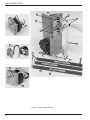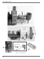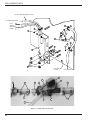
1
Technical Manual
Automatic
Glasswasher
Model
MD18-1
MD18-2
Machine Serial No.
July, 2003
Manual P/N
P.O. Box 4183
Winston-Salem, North Carolina 27115-4183
2674 N. Service Road
Jordan Station, Ontario, Canada L0R 1S0
Moyer Diebel, U.S.
336/661-1992
Fax: 336/661-1979
0509243 REV. F
Moyer Diebel, Ltd.
905/562-4195
Fax: 905/562-4618
Complete the information below so it will be available for quick reference.
Model Number __________________________
Serial Number ________________________
Voltage and Phase ______________________________________________________________
Moyer Diebel Parts Distributor _______________________________
Phone _____________
_____________________________________________________________________________
Moyer Diebel Service Agency ________________________________
Phone _____________
_____________________________________________________________________________
Moyer Diebel Service:
Moyer Diebel Limited
Moyer Diebel, US
Phone:
Phone:
1-905-562-4195
1-800-263-5798
Fax:
1-905-562-4618
1-336-661-1992
1-800-228-8350
Fax:
1-336-661-1660
NOTE: When calling to order parts, be sure to have the model number, serial number, voltage,
and phase of your machine, along with your customer account number.
COPYRIGHT © 2003 by Moyer Diebel
REVISIONS
Revision History
Revision
Date
Revised
Pages
Serial Number
Effectivity
Comments
10/30/95
—
301
Issue of Manual and Replacement Parts
1/xx/97
All
301
Expanded Parts List
3/12/01
18, 19
G2735
3/12/01
24, 25
—
Replacement Impeller, Seal/Gasket kit,
and Inlet Screen
3/11/01
26, 27
—
Added all drain valve components
2/5/03
29
—
Replaced 108391 with 113622 thermometer
7/23/03
17
––
Replaced 110229 with 0310138
Redesign of scrap screen and sump cover
THIS PAGE
INTENTIONALLY
LEFT BLANK
CONTENTS
CONTENTS
Page
WARRANTY ..............................................................................................................................................
1
INTRODUCTION.......................................................................................................................................
2
GENERAL ..................................................................................................................................................
3
INSTALLATION ........................................................................................................................................
5
Unpacking ............................................................................................................................................
5
Electrical Connections..........................................................................................................................
5
Plumbing Connections .........................................................................................................................
6
Detergent ..............................................................................................................................................
6
Rinse-Aid .............................................................................................................................................
6
Chemical Sanitizer ...............................................................................................................................
6
Completing Installation ........................................................................................................................
7
OPERATION ..............................................................................................................................................
8
Operation Summary .............................................................................................................................
8
Operation Procedures ...........................................................................................................................
8
MAINTENANCE........................................................................................................................................ 10
Cleaning Schedule................................................................................................................................ 10
Deliming............................................................................................................................................... 11
Deliming Process.................................................................................................................................. 11
Maintenance Schedule.......................................................................................................................... 12
TROUBLESHOOTING .............................................................................................................................. 13
REPLACEMENT PARTS........................................................................................................................... 15
ELECTRICAL DIAGRAM......................................................................................................................... 36
TIMER CHART .......................................................................................................................................... 37
LIST OF FIGURES
Figure 1—Overall View..................... ......................................................................................................... 15
Figure 2—Door, Tracks, Safety Switch Assembly ..................................................................................... 16
Figure 3—Upper & Lower Wash Arms & Hubs......................................................................................... 18
Figure 4—Fill Valve Assembly................................................................................................................... 20
Figure 5—Chemical Pump Assembly ......................................................................................................... 22
Figure 6—Wash Pump Assembly ............................................................................................................... 24
Figure 7—Fill System & Drain System ...................................................................................................... 26
Figure 8—Heating Element, Thermostat, Temperature Gauge................................................................... 28
CONTENTS
Figure 9—Control Panel and Timer Assembly ......................................................................................... 30
Figure 10—Back Panel................................................................................................................................ 32
Figure 11—Rack ......................................................................................................................................... 34
Figure 12—Wiring Schematic..................................................................................................................... 36
Figure 13—Timer Chart .............................................................................................................................. 37
WARRANTY
LIMITED
WARRANTY
LIMITED WARRANTY
Champion Industries/Moyer Diebel Limited, P.O. Box 4183, Winston-Salem, North Carolina 27115, and P. O. Box 301, 2674
North Service Road, Jordan Station, Ontario, Canada L0R 1S0 warrants machines, and parts, as set out below.
Warranty of Machines: Champion Industries/Moyer Diebel Limited warrants all new machines of its manufacture bearing
the name “Champion” or "Moyer Diebel" and installed within the United States and Canada to be free from defects in
material and workmanship for a period of one (1) year after the date of installation or fifteen (15) months after the date of
shipment by Champion/Moyer Diebel, whichever occurs first. [See below for special provisions relating to Model Series DF
and SW.] The warranty registration card must be returned to Champion/Moyer Diebel within ten (10) days after installation.
If warranty card is not returned to Champion/Moyer Diebel within such period, the warranty will expire after one year from
the date of shipment.
Champion/Moyer Diebel will not assume any responsibility for extra costs for installation in any area where there are
jurisdictional problems with local trades or unions.
If a defect in workmanship or material is found to exist within the warranty period, Champion/Moyer Diebel, at its election,
will either repair or replace the defective machine or accept return of the machine for full credit; provided, however, as to
Model Series DF and SW, Champion/Moyer Diebel's obligation with respect to labor associated with any repairs shall end
(a) 120 days after shipment, or (b) 90 days after installation, whichever occurs first. In the event that Champion/Moyer
Diebel elects to repair, the labor and work to be performed in connection with the warranty shall be done during regular
working hours by a Champion/Moyer Diebel authorized service technician. Defective parts become the property of
Champion/Moyer Diebel. Use of replacement parts not authorized by Champion/Moyer Diebel will relieve Champion/
Moyer Diebel of all further liability in connection with its warranty. In no event will Champion/Moyer Diebel's warranty
obligation exceed Champion/Moyer Diebel's charge for the machine. The following are not covered by Champion/Moyer
Diebel's warranty:
a.
b.
c.
d.
e.
f.
g.
h.
i.
j.
Lighting of gas pilots or burners.
Cleaning of gas lines.
Replacement of fuses or resetting of overload breakers.
Adjustment of thermostats.
Adjustment of clutches.
Opening or closing of utility supply valves or switching of electrical supply current.
Adjustments to chemical dispensing equipment.
Cleaning of valves, strainers, screens, nozzles, or spray pipes.
Performance of regular maintenance and cleaning as outlined in operator’s guide.
Damages resulting from water conditions, accidents, alterations, improper use, abuse,
tampering, improper installation, or failure to follow maintenance and operation procedures.
Examples of the defects not covered by warranty include, but are not limited to: (1) Damage to the exterior or interior finish
as a result of the above, (2) Use with utility service other than that designated on the rating plate, (3) Improper connection to
utility service, (4) Inadequate or excessive water pressure, (5) Corrosion from chemicals dispensed in excess of recommended concentrations, (6) Failure of electrical components due to connection of chemical dispensing equipment installed
by others, (7) Leaks or damage resulting from such leaks caused by the installer, including those at machine table connections or by connection of chemical dispensing equipment installed by others, (8) Failure to comply with local building
codes, (9) Damage caused by labor dispute.
Warranty of Parts: Champion/Moyer Diebel warrants all new machine parts produced or authorized by Champion/Moyer
Diebel to be free from defects in material and workmanship for a period of 90 days from date of invoice. If any defect in
material and workmanship is found to exist within the warranty period Champion/Moyer Diebel will replace the defective
part without charge.
DISCLAIMER OF WARRANTIES AND LIMITATIONS OF LIABILITY. CHAMPION/MOYER DIEBEL'S
WARRANTY IS ONLY TO THE EXTENT REFLECTED ABOVE. CHAMPION/MOYER DIEBEL MAKES NO
OTHER WARRANTIES, EXPRESS OR IMPLIED, INCLUDING, BUT NOT LIMITED TO, ANY WARRANTY OF
MERCHANTABILITY, OR FITNESS OF PURPOSE. CHAMPION/MOYER DIEBEL SHALL NOT BE LIABLE
FOR INCIDENTAL OR CONSEQUENTIAL DAMAGES. THE REMEDIES SET OUT ABOVE ARE THE EXCLUSIVE REMEDIES FOR ANY DEFECTS FOUND TO EXIST IN CHAMPION/MOYER DIEBEL DISHWASHING
MACHINES AND CHAMPION/MOYER DIEBEL PARTS, AND ALL OTHER REMEDIES ARE EXCLUDED,
INCLUDING ANY LIABILITY FOR INCIDENTALS OR CONSEQUENTIAL DAMAGES.
Champion/Moyer Diebel does not authorize any other person, including persons who deal in Champion/Moyer Diebel
dishwashing machines, to change this warranty or create any other obligation in connection with Champion/Moyer Diebel
Dishwashing Machines.
rev. 8699
1
INTRODUCTION
INTRODUCTION
Welcome to Moyer Diebel.
Thank you for choosing Moyer Diebel and for allowing us to take care of your glasswashing/
warewashing needs.
This manual covers two models (MD 18-1, MD 18-2). Model numbers are shown on the front cover.
Your machine has been completely assembled, inspected, and thoroughly tested at our factory to
eliminate problems at installation before it was shipped to your installation site. This manual
provides:
• Warranty information
• Installation and operation procedures
• Maintenance instructions
• Troubleshooting guide
• Replacement parts lists.
• Electrical diagrams.
Complete and return your warranty registration card as soon as possible.
Moyer Diebel constantly improves its products; therefore, specifications contained in this
manual may have changed.
For your protection, factory authorized parts should always be used.
Replacement parts may be ordered from your Moyer Diebel authorized parts distributor or
service agency*. When ordering parts, supply the model number, serial number, voltage and
phase of your machine, the part number, part description, and quantity.
*Moyer Diebel can only ship parts to customers with accounts or by C.O.D.
2
GENERAL
GENERAL
This manual covers the Moyer Diebel automatic glasswashing machine.
Standard equipment includes:
-Automatic tank fill
-Upper and lower wash/rinse arms
-Common utility connections
-Two racks
-120 Volt circuit
-Stainless steel heavy-gauge construction
-Convenient, easy to use controls
-Pumped Drain
-Three chemical pumps
This series of glasswashers is available in the following models:
Model Numbers
MD18-1, MD18-2
•
The MD18-1 model is a single door chemical sanitizing rack glasswashing/warewashing
machine.
•
The MD18-2 model is a two door chemical sanitizing rack glasswashing/warewashing
machine.
(specify front to back or side-to-side operation)
Accessories
• RS19-24 - 19" wide rack stand with 24" high drain board
• RS19-30 - 19" wide rack stand with 30" high drain board
• RS25-24 - 25" wide rack stand with 24" high drain board
• HS1930 - 19" wide hand sink with scrap basket (30" high)
Options
• P/N 0709242 - Cycle Counter
• P/N 0709241 - Remote cycle switch
• Racks - Peg, Flat, Glass
3
GENERAL
Electrical Power Requirements
Model
MD18-1
MD18-2
Voltage
115/60/1
115/60/1
Booster
Rise
N/A
N/A
Machine
Full Load Amp
12
12
Power Requirement
(125% Service Factor)
15
15
NOTE:
All machines come with a 5 Foot cord and plug. Standard 15 amp receptacle required.
4
J5
INSTALLATION
INSTALLATION
Unpacking
!
WARNING:
Care should be taken when lifting the machine to prevent damage.
1.
Immediately after unpacking your machine, inspect for any shipping damage. If damage is
found, save the packing material and contact the carrier immediately.
2.
Remove the glasswasher from the skid. Adjust the feet if required, then move the machine
to its permanent location.
3.
Level the machine (if required) by placing a level on the top of the machine and adjusting
the leveling feet. Level the machine front-to-back and side-to-side.
!
CAUTION:
After locating your machine, it must meet local health codes.
Electrical Connections
J5
!
WARNING:
Electrical and grounding connections must comply with the National Electrical Code
and/or Local Electrical Codes.
!
WARNING:
When working on the glasswasher, disconnect the electric service and tag it to indicate work
is being done on that circuit.
1.
The electrician should compare the electrical specifications on the machine to the
electrical power supply before connecting the machine to the incoming service at a
fused disconnect switch.
2.
Your machine is already equipped with a 5-foot/1.5m power cord and plug suitable for
115V-15A service.
5
INSTALLATION
Plumbing Connections
!
CAUTION:
Plumbing connections must comply with local sanitary and plumbing codes.
Water Connections
1.
Connect the hot water supply (140oF/60oC Min) to the fill solenoid valve (located behind
the front panel). The fill solenoid valve is equipped with a flow control that will accept
water pressures from 20 psi to 70 psi.
2.
Install a manual shut-off valve in the water supply line to accommodate servicing the
machine. The shut-off valve should be the same size or larger than the supply line.
3.
The fill solenoid valve is equipped with a built-in strainer to protect from particles in the
water supply.
Drain Connections
1.
Your Moyer Diebel glasswasher is supplied with a flexible 5/8" I.D. drain hose, which must
be connected to a 1-1/2" drain using a wye (Y) fitting. Additional drain hose may be
purchased from a Moyer Diebel parts distributor.
Detergent
1.
Use a qualified detergent/chemical supplier for your detergent, rinse aid, and chemical
sanitizer needs.
2.
Your machine is supplied with a chemical dispensing system that is internally wired and
ready for use. Insert the labeled Chemical pickup tubes into the correct containers. The
pickup tubes have a strainer on the end to prevent crystallized chemical from clogging the
supply lines.
3.
The cycle timer located in the main control cabinet is equipped with adjustable cams for the
chemical dispensing pump(s). The cams control the length of time that the pumps operate.
A qualified person should adjust the cam settings if necessary. Refer to the timer chart
diagram(s) at the end of the manual for timer cam locations and factory time settings.
NOTE:
A nonchlorinated, nonfoaming commercial detergent is recommended for your glasswasher.
Rinse Aid
1.
Using a liquid rinse aid, insert the labeled Rinse Aid pickup tube into the rinse aid container.
Chemical Sanitizer
6
1.
Using a 5.25% or 8.4% sodium hypochlorite solution, insert the labeled Chemical Sanitizer
pickup tube into the chemical sanitizer container.
2.
Contact your chemical supplier for adjustment of the chemical sanitizer.
INSTALLATION
Completing Installation
1.
Remove any foreign material from inside the machine.
2.
Check to assure scrap basket and sump cover are in place.
3.
After plumbing and electrical connections are completed, check the machine for water leaks
by depressing the ON/FILL switch on the front panel, then close and latch the door(s). This
allows the tank to fill and to complete the rinse cycle. Check for leaks.
4.
Open the door and check the water level. Water level should be at bottom of scrap screen.
5.
Depress the OFF/DRAIN switch, close door, push start switch to drain the tank. This allows
the machine to complete the wash and drain cycle. Check the drain plumbing for leaks.
6.
Installation is now complete.
Indicates where proper
water level should appear
in the inlet chute area.
Front Side
of Tank
7
OPERATION
OPERATION
Operation Summary
The following is a summary of your Glasswashing Machine operating cycle:
1.
The cycle begins when you close the door and push the cycle switch.
2.
The green cycle lamp lights and the pump starts.
3.
The pump runs during the wash cycle.
4.
The pump stops, and the drain valve is opened.
5.
After a 2-3 second pause, the pump drain cycle begins.
6.
After a 2-3 second pause, the fill valve opens, and the pump starts for the rinse cycle.
7.
When the rinse cycle is complete, the pump stops, the green cycle lamp turns off, and the
cycle is complete.
8.
Open the door and remove the rack of clean ware.
Operation Procedures
The operation of your glasswasher will be more efficient when these procedures are followed:
8
1.
Check that the spray arms and scrap basket are in place.
2.
Close the door(s). Push the ON/FILL switch to the ON position. The tank will begin filling
with water. This procedure is followed only when the tank is empty.
3.
When the tank is full, check the wash tank temperature gauge. Minimum wash temperature
is 140°F/60°C.
4.
Scrap all glasses to be washed, and load the glasses into the rack. DO NOT OVERLOAD
THE RACK.
5.
Open the door and insert the rack into the machine.
6.
Shut the door, push cycle switch. This will start the wash cycle. The green cycle lamp
located on the front control panel will light. This lamp will remain on until the entire wash
and rinse cycle is completed.
OPERATION
NOTE:
The machine may be stopped at any time by opening the door. When restarted, the cycle
does not start over. It will continue from the point at which it was interrupted.
7. The pump will automatically stop and the green cycle light will turn off indicating the cycle
is completed.
8. Open the door and remove the rack.
9. Repeat steps 4-9 for additional cycles.
10. CLEAN the scrap basket after every use period. During heavy usage, the scrap basket
should be cleaned more frequently.
!
CAUTION:
Poor machine performance and/or damage to the machine can occur if the scrap
basket becomes clogged with soil or waste particles.
11. After completing usage for the day, water in the tank should be drained by depressing the
OFF/DRAIN switch and closing the door(s). Push the start switch. This initiates a wash and
drain cycle that drains the tank.
!
CAUTION:
DO NOT LEAVE WATER IN THE TANK OVERNIGHT. Water left in the tank
overnight will allow corrosive chemicals to deteriorate the tank.
9
MAINTENANCE
MAINTENANCE
The efficiency and life of your machine is increased by regularly scheduled preventive
maintenance. A well maintained machine gives better results and service. An investment of a few
minutes of daily maintenance will be worthwhile.
The best maintenance you can provide is to keep your machine clean. Components that are not
regularly cleaned and flushed will clog and become inoperative.
Intervals shown in the following schedules represent an average length of time between
necessary maintenance. Maintenance intervals should be shortened whenever your machine is
faced with abnormal working conditions, hard water, or multiple shift operations.
Cleaning Schedule
•
Daily-Every 8 Hours
1. Depress the OFF/DRAIN switch to OFF and close the door. Push cycle switch to drain
the tank.
2. Open the door and remove both the upper and lower spray arms by unscrewing the
knurled fastener holding each spray arm.
3. Remove the scrap basket carefully to keep soil or waste particles from falling into the
sump.
4. Clean inside the tank with clean water. Backflush the scrap basket until it is clean. Do
not strike the scrap basket against solid objects.
5. Clean the wash arms to remove any debris from spray openings. Do not strike the spray
arms against solid objects.
6. Reinstall the scrap basket and spray arms.
7. Leave the door open overnight to allow drying.
8. Report any unusual conditions to your supervisor.
•
Use Periods
1. Clean the scrap basket after every use period and more frequently during heavy usage.
Do not allow the scrap basket to become clogged with soil or waste particles.
10
MAINTENANCE
Deliming
Your glasswasher should be delimed regularly as required. This will depend on the mineral
content of your water.
Inspect your machine interior for lime deposits. If deliming is required, a deliming agent should
be used for best results.
!
DANGER:
Deliming solution or other acids must not come in contact with household bleach (sodium
hypochlorite) or any chemicals containing chlorine, iodine, bromine, or fluorine. Mixing
will cause hazardous gases to form. Skin contact with deliming solutions can cause severe
irritation and possible chemical burns. Consult your chemical supplier for specific safety
precautions.
Contact Chemical supplier for delime chemical and instruction on how to use.
11
MAINTENANCE
Maintenance Schedule
•
•
12
As Required
1.
Check the temperature gauge reading.
2.
Check the chemical supplies and refill as necessary.
Weekly
1.
Inspect all water lines for leaks and tighten them at joints if required.
2.
Clean all detergent residue from the exterior of the machine.
3.
Check the drain for leaks.
4.
Clean accumulated scale from the heating element.
5.
Remove and closely inspect each spray arm for blockage.
6.
Check for damage to the scrap screen. Ineffective screening can cause wash system
failures.
7.
Flush the detergent, sanitizer, and rinse aid supply tubes by the following procedure:
a.
Remove the detergent, sanitizer, and rinse aid pick-up tube(s) from the
container(s). Place the tube(s) into a container of hot water.
b.
Depress and hold the DET prime switch (located on the front panel) until clear
water enters the tank through the fill air gap (located on the side of the tank).
c.
Follow the same procedure by pressing the SANITIZER and/or the RINSE
AID prime switch until clear water enters the tank through the fill air gap.
d.
When completed, remove the pickup tubes from the hot water and reinsert them
into the correct chemical containers. Repeat the priming procedures to ensure
that chemicals have filled the tubes for the next operating period.
e.
Run a complete cycle to flush chemicals from the tank.
TROUBLESHOOTING
TROUBLESHOOTING
Before determining any specific cause of a breakdown or abnormal operation of your
glasswasher, check that:
1.
All switches are ON.
2.
Wash arms are clean.
3.
Scrap screen is properly positioned and clean.
4.
Thermostat(s) are at their correct setting.
5.
Sanitizer, detergent, and rinse additive dispensers are adequately filled.
6.
All plumbing valves are open.
If a problem still exists, use the following table for troubleshooting.
CONDITION
CAUSE
SOLUTION
Machine will not start
Door not closed ..................................
Main switch off, or unit unplugged ....
Make sure door is fully closed
Check disconnect or plug into outlet
Low or no water
Main water supply is turned off .........
Turn on house water supply
Chemical not feeding
No chemical in container.....................
Feed tubes to/from chemical ...............
pump clogged
Screen on feed tube clogged................
Tubing kinked or split .........................
Replace or fill container
Clear obstruction and flush
with hot water
Clean and replace
Straighten or replace tubing
Water temperature
is low when in use
Incoming water temperature................
at machine too low
Raise temperature to
60°C/140°F for all machines
Insufficient pumped spray
pressure
Clogged spray arm ..............................
Scrap screen full ..................................
Clean
Must be kept clean and in place
Poor washing results
Detergent dispenser not.......................
operating properly
Insufficient detergents .........................
Contact service agent
Detergent setting too low ...................
Wash water temperature too low.........
Wash arm clogged ..............................
Improperly scrapped glasses ...............
Ware being improperly........................
placed in rack
Improperly cleaned .............................
equipment
Electric element has ............................
soil/lime buildup
Machine overflows on
to floor
Wash pump impeller ...........................
plugged with trash
Check and fill
Contact detergent supplier
Contact detergent supplier
Check incoming water temp
Clean wash arm
Check scrapping procedures
Use proper racks - do not overload
racks
Unclog wash arms to maintain
proper pressure and flow conditions
Clean and delime
Remove pump assembly and clean impeller
13
TROUBLESHOOTING
TROUBLESHOOTING
CONDITION
14
CAUSE
SOLUTION
No water in wash well
Opening door prior ..............................
to cycle completion
Close door. Wait for green cycle light
to go out before opening door.
No water in wash tank
after activating the
ON/FILL switch
Door not closed ...................................
Close door.
Wait for wash tank to fill.
OVERALL VIEW
MODEL MD18-1
1
2
5
6
3
4
Figure 1 — Overall View of MD18-1
Fig. 1
Part
Item No. No.
1
0709072
0709074
1
0709421
2
0709069
0309085
3
4
111370
5
0508751
6
0509671
6
112587
Description
Hood, one door model................................................................
Hood, two door model................................................................
Hood, welded (High hood models only) ....................................
Door, service ..............................................................................
Hinge, service door ....................................................................
Screw (10-32 x 5/8 hex hd w/washer SS) ..................................
Screw (10-32 x 1-1/2 truss hd SS) .............................................
Legs 4" (Optional)......................................................................
Legs 6" .......................................................................................
Qty
1
1
1
1
1
2
1
4
4
15
REPLACEMENT PARTS
1
2
3
2
1
4
7
5
6
14
8
8
9
10
11 12 13
15 16
13 12 11
18
22
21
20
19
17
24
23
25
Figure 2 — MD18-1, MD18-2 Door, Tracks, Safety Switch
16
REPLACEMENT PARTS
MD18-1, MD18-2
DOOR, TRACKS, SAFETY SWITCH
Fig. 2
Part
Item No. No.
1
110228
2
0310138
3
0709071
3
0709414
4
5
6
7
8
9
10
11
12
13
14
*15
*16
17
18
19
20
21
22
#23
#24
#25
26
0501538
0501497
0501425
110233
107137
0309123
0309124
0501539
0501501
0501419
107893
0309301
0309102
0509251
0501539
104985
0501412
111026
111090
0309228
0309229
0309236
0501449
27
108954
Part Description
Pin, door .....................................................................................
Support, door..............................................................................
Door assembly (Does not include items 1, 2, 4-7,
17, 18) MD18-1..........................................................................
MD18-2 ......................................................................................
Door Assembly (Does not include items 1, 2, 4-7, 17, 18)
High hood only...........................................................................
Nut (8-32 SS) .............................................................................
Lockwasher ................................................................................
Screw (8-32 x 5/8 rd hd SS) .......................................................
Catch, door .................................................................................
Bolt (10-32 x 7/8 hex SS)...........................................................
Guide, rack RH...........................................................................
Guide, rack LH...........................................................................
Nut (1/4-20 SS) ..........................................................................
Lockwasher ................................................................................
Bolt (1/4-20 x 1/2 hex SS)..........................................................
Shock absorber, door, per door ..................................................
Bracket, door magnet, long ........................................................
Bracket, door magnet, short .......................................................
Thumbscrew (1/4-20 x 2-3/4 SS), per door................................
Nut (1/4-20 x 1/2 SS), per door .................................................
Nut (10-32 SS), per door ............................................................
Screw (10-32 x 3/8 truss hd SS), per door .................................
Magnet, door safety, per door.....................................................
Switch, magnetic reed, per door.................................................
Bracket, front switch mounting..................................................
Bracket, rear switch mounting ...................................................
Bracket, corner switch mounting ...............................................
Screw (6-32 x 3/8 rd hd SS) (Not shown)
per switch bracket.......................................................................
Nut (6-32 SS Nylite) (Not shown), per switch bracket ..............
Qty
2
2
1
2
1
2
2
2
1
4
1
1
4
4
4
2
A/R
A/R
1
1
2
2
1
1
A/R
A/R
A/R
2
2
* MD18-1 Requires (1) 0309301 bracket.
MD18-2 Front-to-Back configuration requires (1) 0309301 and (1) 0309102.
MD18-2 Side-to-Side configuration requires (2) 0309301.
# MD18-1 Requires (1) 0309228.
MD18-2 Front-to-Back requires (1) 0309228 and (1) 0309229.
MD18-2 Side-to-Side requires (1) 0309228 and (1) 0309236.
17
REPLACEMENT PARTS
1
4
2
3
9
8
6
5
7
10
13
14
11
12
After Serial # G2735
1
15
16
19
17
20
18
21
18
Figure 3 — Upper & Lower Wash Arms & Hubs
REPLACEMENT PARTS
MD18-1, MD18-2
UPPER & LOWER WASH ARMS & HUBS
Fig. 3
Item No.
1
1
2
3
4
4
5
6
7
8
9
10
11
12
13
14
15
16
17
18
19
20
21
Part
No.
0709105
0710339
0309113
107964
0709479
0710339
0709131
0505042
0308783
0501563
0508541
0709130
0709127
0501684
0308158
0501563
0505044
0709126
0709134
0501419
0309212
0708650
0501412
0507265
0508808
Part Description
Scrap screen assembly (Prior to Serial no. G2735) ....................
Scrap screen assembly (After Serial no. G2735)........................
Cover, wash tank ........................................................................
Grommet, snap bushing..............................................................
Cover, sump assy. (Prior to Serial no. G2735) ...........................
Scrap Screen (After Serial no. G2735).......................................
Upper spray arm, without bearing ..............................................
Upper spray arm pivot ................................................................
Clip, pivot retaining....................................................................
Screw (8-32 x 3/8 truss hd SS) ...................................................
Support, upper spray arm ...........................................................
Complete upper wash arm assembly (Includes items 5-9)
Lower spray arm, without bearing..............................................
Locknut.......................................................................................
Clip, locknut retaining ................................................................
Screw (8-32 x 3/8 truss hd SS) ...................................................
Support, lower spray arm ...........................................................
Complete lower wash arm assembly (Includes items 11-15)
Lower wash arm manifold..........................................................
Bolt (1/4-20 x 1/2 hex SS)..........................................................
Gasket, manifold.........................................................................
Manifold, upper wash arm..........................................................
Screw (10-32 x 3/8 truss hd SS) .................................................
Hose 5/8 ID x 7/8 OD, per ft. .....................................................
Clamp, 3/4 gear SS .....................................................................
Qty
1
1
1
2
1
1
1
1
1
2
1
1
1
1
2
1
1
4
1
1
3
3
1
19
REPLACEMENT PARTS
9
10
5
8
4
7
3
6
1
2
9
10
14
11
13
12
Solenoid Valve Detail
Figure 4 — Fill Valve Assembly
20
REPLACEMENT PARTS
MD18-1, MD18-2
FILL VALVE ASSEMBLY
Fig. 4
Item No.
1
2
3
4
5
6
7
8
9
10
11
12
13
14
Part
No.
0504952
0503713
0502618
0300203
0300065
0502653
0502618
0503679
0507265
0501419
0501501
0502811
0504958
0502803
0505235
Description
Valve, fill solenoid......................................................................
Elbow, street 1/2 FPT x 3/8 MPT...............................................
Coupling, reducing 1/2 FPT x 3/8 MPT.....................................
Clamp, fill valve support............................................................
Support, fill valve.......................................................................
Elbow, 3/8 MPT x 1/2 hose (90 degree).....................................
Coupling, reducing 1/2 FPT x 3/8 MPT (Straight) ....................
Clamp, hose................................................................................
Hose, 5/8 ID x 7/8 OD PVC braid .............................................
Bolt (1/4-20 x 1/2 hex SS)..........................................................
Lockwasher ................................................................................
Kit, valve repair..........................................................................
Washer, flow...............................................................................
Screen .........................................................................................
Coil, 115VAC .............................................................................
Qty
1
1
1
1
1
1
1
1
1
3
3
1
1
1
1
21
REPLACEMENT PARTS
12
11
2
3
10
2
16
17
18
1
4
21
20
8
20
9
2
5
22
14
15
19
Figure 5 — Chemical Pump Assembly
22
6
13
7
REPLACEMENT PARTS
MD18-1, MD18-2
CHEMICAL PUMP ASSEMBLY
Fig. 5
Item No.
1
2
3
4
5
6
7
8
9
10
11
12
Part
No.
0709100
0501519
0502666
0502667
0501419
0501501
0306363
0501869
0502644
0309101
0504822
0506589
13
14
15
16
17
0503695
0503694
0505483
0503756
0706635
18
19
20
21
22
0707142
0503757
109829
108194
0501425
Description
Chemical pump assembly...........................................................
Tie, nylon 4 inch (One at each indication) .................................
Hose, 1/8 ID x 1/4 OD, per foot.................................................
Hose, 1/4 ID x 3/8 OD, per foot.................................................
Bolt (1/4-20 x 1/2 hex SS)..........................................................
Lockwasher ................................................................................
Tubing, stiffener .........................................................................
Strainer .......................................................................................
Elbow, 1/4 hose barbed ..............................................................
Bracket, chemical pump.............................................................
Screw (8-32 x 1/2 pan hd Phillips SS) .......................................
Screw (6-32 x 7/8 pan hd Phillips SS) .......................................
(2 each included with item 17, element tube)
Label, “DETERGENT”..............................................................
Label, “SANITIZER”.................................................................
Label, “RINSE”..........................................................................
Motor, injector............................................................................
Tube, element assembly 45 cc....................................................
(Includes mounting screws)
Rotor assembly...........................................................................
Motor, pump drive, with reducer................................................
Pump, detergent..........................................................................
Tube, 3/16 ID x 3/8 OD..............................................................
Screw (8-32 x 5/8 rd hd SS) .......................................................
Qty
1
6
A/R
A/R
2
2
3
3
2
1
10
4
1
1
1
2
2
2
1
1
1
2
23
REPLACEMENT PARTS
2
4
3
See block below
for new impeller
and Seal/Gasket
kit. This style no
longer available.
1
8
9
6
7
5
10
Figure 6 — Wash Pump Assembly
24
REPLACEMENT PARTS
MD18-1, MD18-2
WASH PUMP ASSEMBLY
Fig. 6
Item No.
1
2
3
4
5
6
7
8
9
10
11
Part
No.
0509096
0509235
0502571
0509239
0509282
0509303
0510222
0501419
0501501
0709393
0510221
Description
Pump, wash MD-18....................................................................
Hose, 1-1/4 x 1-5/8 braided (3 inch length) ...............................
Clamp, 1-1/2 gear .......................................................................
Elbow, 1-1/4 hose x 1 FPT PVC ................................................
Capacitor, motor starting ............................................................
Housing, pump kit ......................................................................
(Includes 8-32 x 1-3/4 round head Phillips screws
and #8 washers)
Kit, Seal and gasket ....................................................................
Bolt (1/4-20 x 1/2 hex SS)..........................................................
Lockwasher.................................................................................
Screen, inlet ................................................................................
Impeller, Stainless Steel..............................................................
Qty
1
1
2
1
1
1
1
4
4
1
1
25
REPLACEMENT PARTS
(See Corresponding Pump For Hose)
From Detergent Pump
From
Sanitizer
Rinse-aid
Pumps
4
3
4
5
5
3
14
1
2
3
4
5
6
7
5
Front Side
of Tank
From Fill Valve
11
16
13
14
12
19
15
17
18
15
14
9
10
Figure 7 — Fill System & Drain System
26
14
REPLACEMENT PARTS
MD 18-1, MD 18-2
FILL SYSTEM AND DRAIN SYSTEM
Fig. 7
Item No.
1
2
3
4
5
6
7
8
*9
—
—
10
11
—
12
13
14
15
16
17
18
19
Part
No.
0507265
0509324
0501518
106090
107966
0509048
0508867
0501519
0709223
0509224
0509225
0509302
0709285
0509225
0509184
0709134
0503679
0509235
0509226
0709252
0709140
0309392
Description
Hose, 5/8 ID x 7/8 OD PVC braided..........................................
Elbow, 5/8 inch 90° plastic barbed.............................................
Tie, nylon 5-1/2 inch ..................................................................
Plate, tie wrap bracket ................................................................
Nut (10-32 Nylite)......................................................................
Gasket, inlet chute ......................................................................
Chute, inlet .................................................................................
Tie, nylon 4 inch (Not shown)....................................................
Valve, drain (Complete assembly) ............................................
Body, drain valve (Body only) (Not shown) ..............................
Gasket drain cover (Not shown).................................................
Hose, 5/8 ID x 7/8 OD x 60 inch braided...................................
Solenoid, drain valve .................................................................
Solenoid coil, drain valve (Not shown)......................................
Pipe, valve extension..................................................................
Manifold, bottom........................................................................
Clamp, hose ...............................................................................
Hose, 1-1/4 ID x 1-5/8 OD x 4 inch braided..............................
Spring, drain valve .....................................................................
Flapper pivot assembly...............................................................
Drain flapper assembly...............................................................
Valve support bracket .................................................................
Qty
3
1
2
2
7
1
1
3
1
A/R
1
1
1
1
1
1
5
26
1
1
1
1
* 0709223 Includes items 11, 16, 17, 18
27
REPLACEMENT PARTS
1
2
4
10
9
3
8
5
6
7
11
Figure 8 — Heating Element, Thermostat, Temperature Gauge
28
REPLACEMENT PARTS
MD18-1, MD18-2
HEATING ELEMENT, THERMOSTAT, TEMPERATURE GAUGE
Fig. 8
Item No.
1
2
3
4
5
6
7
8
9
10
11
Part
No.
0501650
0501836
0507323
108954
110562
0507315
0503588
0501412
0501450
0300096
113622
Description
Adapter, thermostat ....................................................................
O-ring, thermostat adapter..........................................................
Thermostat, wash tank................................................................
Nut (6-32 Nylite)........................................................................
Thermostat, bi-metal ..................................................................
Heater, 240 Volt 3kw (Includes O-ring) .....................................
O-ring, replacement (Included with heater) ...............................
Screw (10-32 x 3/8 truss hd) ......................................................
Screw (6-32 x 1/4 round hd NIBS) ............................................
Bracket, thermostat.....................................................................
Thermometer, flange type 4 ft./1.2 M Gas Filled (Includes
mounting hardware) (Replaces 108391) ....................................
Qty
1
1
1
2
1
1
1
2
2
1
1
29
REPLACEMENT PARTS
1
2
3
4
8
7
5
9
12
6
10
14
11
13
Figure 9 - Control Panel and Timer Assembly
30
REPLACEMENT PARTS
MD18-1, MD18-2
CONTROL PANEL AND TIMER ASSEMBLY
Fig. 9
Part
Item No. No.
1
0509090
0509363
2
0509089
3
0501361
4
0501369
5
0503749
6
0503648
7
0308644
8
0501408
9
0501450
10
0509227
11
0501379
12
0503701
13
111068
14
0501408
–
0709076-S
Description
Overlay, switch (ENGLISH) ......................................................
Overlay, switch (FRENCH) .......................................................
Switch, lighted push button........................................................
Switch, rocker DPDT .................................................................
Switch, spring return ..................................................................
Board, terminal 11 point.............................................................
Screw (8-32 x 5/16 NIBS pan hd SS) ........................................
Bracket, timer support ................................................................
Screw (8-32 x 1/4 truss hd SS)...................................................
Screw (6-32 x 3/16 NIBS Round hd SS)....................................
Motor, timer................................................................................
Switch, timer ..............................................................................
Bearing, timer shaft ....................................................................
Relay, 2PDT 10A 120VAC ........................................................
Screw (8-32 x 1 truss hd SS)......................................................
Timer & Cam Assembly (Includes items 7-12)
Qty
1
1
1
1
2
1
1
1
4
2
1
8
1
1
2
31
REPLACEMENT PARTS
1
2
3
4
Figure 10 — Back Panel and Cover Support Bracket
32
REPLACEMENT PARTS
MD18-1, MD18-2
BACK PANEL AND COVER SUPPORT BRACKET
Fig. 10
Item No.
1
2
3
4
Part
No.
0309237
0501412
104985
0309238
Description
Panel, rear...................................................................................
Screw (10-32 x 3/8 truss hd SS).................................................
Nut (10-32 SS) ...........................................................................
Support, tank cover ....................................................................
Qty
1
4
2
1
33
REPLACEMENT PARTS
1
2
3
4
Figure 11 — Racks
34
REPLACEMENT PARTS
MD18-1, MD18-2
RACKS
Fig. 11
Item No.
1
2
3
4
Part
No.
110353
112142
112141
110352
Part Description
Rack, flat 16 in. ..........................................................................
Divider, lower glassrack.............................................................
Divider, upper glassrack.............................................................
Rack, peg 16 in...........................................................................
Qty
1
4
4
1
* Glassracks using adjustable dividers may be made up with either 16, 25, or 36 compartments.
Number of compartments determines the number of dividers needed.
35
ELECTRICAL DIAGRAM
TO CUSTOMER RECEPTACLE
115V 60Hz
BLK
WHT
CUSTOMER TO SUPPLY RATED VOLTAGE/PHASE/Hz,
AS SPECIFIED PER ORDER, TO DISCONNECT SWITCH.
ALL POWER SUPPLIED TO EACH CONNECTION POINT
MUST COMPLY WITH ALL LOCAL ELECTRIC CODES.
GND
1
1
2
WTS
MSW
8
RL
NO
4
NO
5
6
2
8
CAM 8
NC
24
2
TM
NC
BRN
1
24
BRN
START
CAPACITOR
NO
CAM 2
NC
WASH PUMP
BLK
RC
NO
19
CAM 3
NC
8
15
V
D
2
2
3
24
4
BLK
WHT
GRN
GND
ON TWO DOOR
MODEL MD-18-2 ONLY
NO
20
CAM 4
NC
8
16
F
V
2
2
NO
CAM 5
NC
8
21
RM
2
STATE OF DIAGRAM
PSDR
1
1
17
MOMENTARY
NO
CAM 7
NC
8
22
DM
2
- Power Off
- Beginning of cycle
- Door Closed
PSS
1
1
18
MOMENTARY
8
NO
CAM 6
NC
23
SM
2
MD-18
Single Phase
BLK
BLACK
DM
DETERGENT MOTOR
RL
BLU
BLUE
DV
DRAIN VALVE
RM
RELAY CONTACT
RINSE MOTOR
CAM 1
HOMING
FV
FILL VALVE
RS
REED SWITCH
CAM 2
PUMP MOTOR
GND
GROUND
SM
SANITIZER MOTOR
CAM 3
DRAIN
GRN
GREEN
TM
TIMER MOTOR
CAM 4
FILL
HTLS
HIGH LIMIT THERMOSTAT
TP
THERMAL PROTECTOR
CAM 5
RINSE
MSW
MAIN SWITCH ON/OFF
WHT
WHITE
CAM 6
SANITIZER
PSB
PUSHBUTTON START SWITCH
WHTR
CAM 7
DETERGENT
PSDR
PRIME SWITCH - DETERGENT, RINSE
WTS
CAM 8
AUTO FILL/DRAIN CYCLE
PSS
PRIME SWITCH - SANITIZER
CLT
CYCLE ON LIGHT
RC
RELAY COIL
WATER HEATER
WATER THERMOSTAT
A0509232/A
Figure 12 — Wiring Schematic
36
2
NO
CAM 1
NC
8
RS
WHTR
CLT
9
RS
11
PSB START
3
OFF/DRAIN
HLTS
10
3
ON/FILL
TIMER CHART
Figure 13 — MD-18 Timer Assembly
37