1
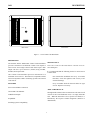
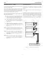
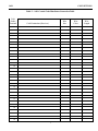
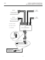
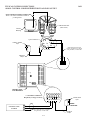
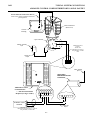
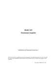
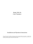
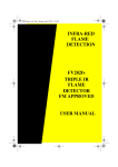
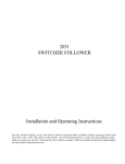
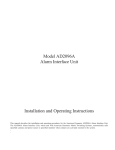
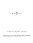
1691
Control Code Distributor
INSTALLATION INSTRUCTIONS
The AD1691 and the ADS1691FX Control Code Distributors provide a maximum of 64 buffered Control Code outputs
to AD receivers from a single Control Code Source input. Each output will drive up to 5000 feet (1524m) on 18AWG,
shielded, twisted pair cable. One Control Code Distributor processes information for a maximum of 64 receivers. All
versions of the 1691 are compatible with all American Dynamics Matrix Switching Systems and Control Codes
sources.
The software/firmware furnished with this equipment is confidential to and is copyrighted by SENSORMATIC ELECTRONICS
CORPORATION. It is not to be copied or disclosed in any manner without the express written consent of SENSORMATIC. The
software/firmware is furnished to the purchaser under a license for use on a single system.
Information furnished by SENSORMATIC is believed to be accurate and reliable. However, no responsibility is assumed by
SENSORMATIC for its use; nor for any infringements of other rights of third parties which may result from its use. No license is
granted by implications or otherwise under any patent or patent rights of SENSORMATIC.
Copyright 1997 by Sensormatic. All rights reserved.
AMERICAN
DYNAMICS
The installation of this product should be made by qualified
service personnel and should conform to all local codes.
CAUTION
RISK OF ELECTRIC SHOCK
DO NOT OPEN
The lightning flash with arrowhead
symbol, within an equilateral
triangle, is intended to alert the
user to the presence of uninsulated
"dangerous voltage" within the
product's enclosure that may be of
sufficient magnitude to constitute a
risk of electric shock to persons.
!
CAUTION: TO REDUCE THE RISK OF ELECTRIC SHOCK,
DO NOT REMOVE COVERS (OR BACK) .
NO USER-SERVICEABLE PARTS INSIDE.
REFER SERVICING TO QUALIFIED SERVICE PERSONNEL
WARNING
!
The exclamation point within an
equilateral triangle is intended to
alert the user to the presence of
important operating and maintenance
(servicing) instructions in the
literature accompanying the product.
UNPACKING AND INSPECTION
To reduce the risk of fire or shock hazard, do
not expose this product to rain or moisture.
Unpack carefully. This is an electronic product and should
be handled as such. Compare the items received with the
packing list with your order.
This equipment has been tested and
found to comply with Part 15 of the
FCC Rules.
Be sure to save:
1. The shipping cartons and insert pieces. They are the
safest material in which to make future shipments of
the product.
2. The IMPORTANT SAFEGUARDS sheet.
3. These Installation and Operating Instructions.
Operation is subject to the
following two conditions: 1. This
device may not cause harmful
interference, and 2. This device
must accept any interference
received, including interference
that may cause undesired operation.
)
MAINTENANCE
User maintenance of this unit is limited to external cleaning
and inspection. For specific recommendations refer to the
IMPORTANT SAFEGUARDS sheet packaged with this product.
INSTALLATION AND SERVICE
If you require information during installation of this
product or if service seems necessary, contact the
Sensormatic Repair and Service Department at (800)
442-2225. You must obtain a Return Authorization Number
and shipping instructions before returning any product for
service.
Do not attempt to service this product yourself. Opening or
removing covers may expose you to dangerous voltages or
other hazards. Refer all servicing to qualified personnel.
QA301D
Table of Contents
DESCRIPTION . . . . . . . . . . . . . . . . . . . . . . . . . . . . . . . . . . . . . . . . . . . . . . . . . . . . . . .
1
FEATURES . . . . . . . . . . . . . . . . . . . . . . . . . . . . . . . . . . . . . . . . . . . . . . . . . . . . . . . . . .
1
MAINTENANCE . . . . . . . . . . . . . . . . . . . . . . . . . . . . . . . . . . . . . . . . . . . . . . . . . . . . . .
1
ABOUT THIS MANUAL . . . . . . . . . . . . . . . . . . . . . . . . . . . . . . . . . . . . . . . . . . . . . . .
1
INSTALLATION . . . . . . . . . . . . . . . . . . . . . . . . . . . . . . . . . . . . . . . . . . . . . . . . . . . . . .
Mounting . . . . . . . . . . . . . . . . . . . . . . . . . . . . . . . . . . . . . . . . . . . . . . . . . . . . . . . . .
Mounting Surfaces . . . . . . . . . . . . . . . . . . . . . . . . . . . . . . . . . . . . . . . . . . . . . . . . . .
2
2
2
CONNECTIONS . . . . . . . . . . . . . . . . . . . . . . . . . . . . . . . . . . . . . . . . . . . . . . . . . . . . . .
Model AD1691 Power Connections . . . . . . . . . . . . . . . . . . . . . . . . . . . . . . . . . . . .
Code Source Connections . . . . . . . . . . . . . . . . . . . . . . . . . . . . . . . . . . . . . . . . .
Model ADS1691FX Power Connections . . . . . . . . . . . . . . . . . . . . . . . . . . . . . . . . .
Code Source Connections . . . . . . . . . . . . . . . . . . . . . . . . . . . . . . . . . . . . . . . . .
Code Output Connections - All Models . . . . . . . . . . . . . . . . . . . . . . . . . . . . . . . . . .
Connection Tables . . . . . . . . . . . . . . . . . . . . . . . . . . . . . . . . . . . . . . . . . . . . . . . . . .
3
3
3
4
4
5
6
TYPICAL CONNECTIONS
1691
FROM
AD1691
FROM
ADS1691FX FROM
AD1691
TO
ADS1691FX TO
AD1691
TO
ADS1691FX TO
AD1691
TO
ADS1691FX TO
A-1
A-2
A-3
A-4
A-5
A-6
A-7
A-8
A-9
AD1202 P/T Controller . . . . . . . . . . . . . . . . . . . . . . . . .
AD2350 Switcher . . . . . . . . . . . . . . . . . . . . . . . . . . . . .
AD2350 Switcher . . . . . . . . . . . . . . . . . . . . . . . . . . . . . .
AD1241 Pan/TIlt . . . . . . . . . . . . . . . . . . . . . . . . . . . . . .
AD1241 Pan/TIlt . . . . . . . . . . . . . . . . . . . . . . . . . . . . . .
AD1242 Pan/TIlt . . . . . . . . . . . . . . . . . . . . . . . . . . . . . .
AD1242 Pan/TIlt . . . . . . . . . . . . . . . . . . . . . . . . . . . . . .
AD1270 Series DOME . . . . . . . . . . . . . . . . . . . . . . . . . .
AD1270 Series DOME . . . . . . . . . . . . . . . . . . . . . . . . .
SPECIFICATIONS . . . . . . . . . . . . . . . . . . . . . . . . . . . . . . . . . . . . . . . . . . . . . . . . . . . . .
i
Back
Cover
1691
ii
1691
DESCRIPTION
CODE LED
Rear View
Front View
Figure 1 - 1691 Control Code Distributor
DESCRIPTION
MAINTENANCE
The AD1691 and the ADS1691FX Control Code Distributors
provide a maximum of 64 buffered Control Code outputs to
AD receivers from a single Control Code Source input. Each
output will drive up to 5000 feet (1524m) using 18AWG,
shielded, twisted pair cable.
The 1691 Control Code Distributor contains no userserviceable parts.
It is recommended that the following checks be carried out on
a routine basis:
One Control Code Distributor processes information for a
maximum of 64 receivers. The AD1691 is compatible with all
American Dynamics Matrix Switching Systems and Control
Code sources.
One month after installation and every six months
thereafter, check the tightness and security of all
external fastenings.
Every six months check all electrical cables for signs
of wear. Replace if necessary.
FEATURES
Screw Terminal Wire Connectors
ABOUT THIS MANUAL
Green LED Code Indicator
Throughout this manual, when an instruction is the same for all
versions of the Code Distribution Unit, it is simply called the
1691. When the instruction is for a specific 1691 model, it is
identified by the respective model designation (AD1691 or
ADS1691FX).
64 Buffered Outputs
Expandable
Switching System Compatibility
1
INSTALLATION
1691
Installation
Mounting Surfaces
This installation should be made by qualified service personnel
and should conform to all local codes. Safeguards must be
taken to avoid unintentional operation by employees, janitors,
and cleaners working about the premises, by falling objects, by
customers, by building vibration, and by similar causes.
Mount all versions of the 1691 with 1/4-inch diameter bolts
appropriate to the type of mounting surface.
Wood Surfaces
For mounting to wood studs, use lag bolts (with a drilled
pilot hole) or wood screws which penetrate the wood for
at least one and a half inches (1.5”).
Mounting
The 1691 Code Distributors are designed for indoor use only.
The units may be surface mounted via the mounting openings
on each side of the 1691 housing (total of four mounting
openings).
Concrete Surfaces
In concrete, use lead or plastic anchor expansion bolts
with a minimum pull-out rating of 25 pounds.
The overall dimensions for all versions of the 1691 unit are as
follows (see Figure 2):
Height (top to bottom): 12”
(305mm)
Width (side to side):
14”
(356mm)
Depth (front to back):
4”
(102mm)
Steel Surfaces
For steel surfaces, drill four clearance holes and use bolts
with lockwashers and nuts.
Drywall Surfaces
For drywall (gypsum) surfaces, use toggle bolts. Note that
the drywall surface must be at least 3/8”.
Figure 2 - 1691 Dimensions (all versions) and Mounting Specifications
2
1691
INSTALLATION
Connections
Code Source Connections
Model AD1691 Power Connections
- WARNING Do not connect the AD1691 to the primary power
source until ALL connections and switch settings
have been completed and verified.
The AD1691 is supplied with a wall transformer (AD part
number TP8002) which can be connected to an outlet for
primary power.
Connect one of the 12 Volt AC leads from the TP8002
Transformer to one of the designated AC terminals on
the AD1691 (see Figure 3).
The AD1691 has three terminals for receiving control code
from a suitable Control Code Source such as the AD1202 P/T
Controller. The terminals are designated B for black, W for
white, and S for shield.
B Connect a black code wire from the B terminal of the
Control Code Source to the B terminal of the AD1691
Control Code Distributor (see Figure 3).
W Connect a white code wire from the W terminal of the
Control Code Source to the W terminal of the AD1691
Control Code Distributor.
NOTE: A 120Ω 1/4Watt termination resistor must be inserted
between the B and the W code wires (see Figure 3-A).
Connect the second 12 Volt AC lead from the TP8002
Transformer to the remaining AC terminal on the
AD1691.
S Connect one end of the shield cable to the S terminal
of the Control Code Source. Connect the opposite end
of the shield cable to the S terminal of the AD1691
Control Code Distributor.
Plug the TP8002 Transformer into a suitable 120VAC
power source (wall outlet, extension cord, etc.).
NOTE: Use 18 Awg, shielded, 2-wire cable, Belden 8760 or
equivalent for code line connections. The maximum
cable length is 5000 feet. For plenum wiring, use
Belden 88760 or equivalent.
CODE LED
Figure 3-A
Code Line Termination
W
B
120Ω 1/4Watt
Termination Resistor
J6
(Not Supplied)
AD1691 Control
Code Distributor
S
120VAC, 60Hz
Input
AC AC
W B
TP8002
Transformer
W
CONTROL CODE
SOURCE
B
S
Maximum Distance between
AD1691 and Code source is 5000 Ft,
using shielded, 18 AWG cable
Figure 3 -- AD1691 Power and Code Source Connections
3
12Volts AC
Output
CONNECTIONS
1691
Model ADS1691FX Power Connections
Code Source Connections
- WARNING Do not connect the ADS1691FX to the primary
power source until ALL connections and switch
settings have been completed and verified.
The ADS1691FX has three terminals for receiving control
code from a suitable Control Code Source such as the AD1202
P/T Controller. The terminals are designated B for black, W
for white, and S for shield.
The ADS1691FX is provided with a separate power supply
(Sensormatic part number 0300-0914-02) that includes a Euro
style IEC 320 type inlet.
B Connect a black code wire from the B terminal of the
Control Code Source to the B terminal of the
ADS1691FX Control Code Distributor (see Figure 4).
A suitable detachable cord should be connected between the
IEC 320 inlet and the power source. The cord should conform
to all specific country and locality code requirements.
W Connect a white code wire from the W terminal of the
Control Code Source to the W terminal of the
ADS1691FX Control Code Distributor.
- WARNING Connection to any other voltage source may
result in damage to the ADS1691FX.
NOTE: A 120Ω 1/4Watt termination resistor must be inserted
between the B and the W code wires (see Figure 4-A).
On the secondary side of the power supply, connect only the
COM and the 12V output lines to the ADS1691FX (see
Figure 4).
S Connect one end of the shield cable to the S terminal
of the Control Code Source. Connect the opposite
end of the shield cable to the S terminal of the
ADS1691FX Control Code Distributor.
- CAUTION For the 230V power supply (Sensormatic part
number 0300-0914-02), verify that the selector
switch is set to “240”. The selector switch is
located adjacent to the IEC 320 inlet. If any
other voltage is indicated, remove the assembly,
select the “240” setting and reinsert the assembly,
allowing it to snap into place.
NOTE: Use 18 Awg, shielded, 2-wire cable, Belden 8760 or
equivalent for code line connections. The maximum
cable length is 5000 feet.
Figure 4-A
Code Line Termination
Sensormatic
Model# 0300-0914-02
Transformer
CODE LED
W
J6
B
120Ω 1/4Watt
Termination Resistor
(Not Supplied)
ADS1691FX Control
Code Distributor
230V, 50/60Hz
Input
Maximum Distance between
ADS1691FX and Code source is 5000 Ft,
using shielded, 18 AWG cable
S W B AC AC
2
3
4
COM
W
CONTROL CODE
SOURCE
1
12V
B
S
12Volts AC
Output
Figure 4 -- ADS1691X Power and Code Source Connections
4
5
6
1691
CONNECTIONS
Code Output Connections - All Models
Daisy Chain Connection
The 1691 Code Distribution Unit provides 64 code line outputs
from a single code line input.
Each code line can accommodate a maximum of three codecontrolled units in a “Daisy Chain” configuration of less than
500 feet.
Each of the 64 code line outputs is through individual external
connectors each with three output terminals for camera control
commands (camera pan/tilt/lens/preset/aux) to AD Manchester
Control Code units, such as camera site receivers.
NOTE: Terminate only the last unit on the code line in 120
ohms.
If additional equipment is required on a code line, or of longer
distances are involved, Code Distribution Units must be used.
Each code line can accommodate a maximum of three code
receivers in a “daisy chain” configuration of less than 5000
feet, as illustrated in Figure 5, below). The last unit in the
daisy chain must be terminated with a 120Ω 1/4 Watt resistor.
Each of the three output terminals are designated B for black,
W for white, and S for shield.
B Connect a black code wire from the B terminal on the
1691 to the B terminal of a suitable Manchester Code
receiver (see Figure 3, Page 3, or Figure 4, Page 4).
W Connect the white code wire from the W terminal on
the 1691 to the W terminal of a suitable Manchester
Code receiver.
S Connect one end of the shield cable between the 1691
and the receiver to the S terminal. Connect the
opposite end of the shield cable to the S terminal of
the receiver.
Code Receiver #3*
B
W
S
* = 120Ω Termination
NOTE: AD Receivers feature built-in termination on their
logic boards. Verify the termination requirements of
non AD units before completing the connections.
Code Receiver #2
NOTE: Use 18 Awg, shielded, 2-wire cable, Belden 8760 or
equivalent for code line connections. The maximum
cable length is 5000 feet. For plenum wiring, use
Belden 88760.
Code Receiver #1
B
W
S
B
W
S
NOTE: Tables One and Two (pages 6 and 7, respectively),
provide space to record basic connection information
between the 1691 Code Distribution Unit and up to 64
code receivers.
S W B
1691 Code Distributor
Figure 5 -- 1691 Daisy Chain Configuration
5
CONNECTIONS
1691
Table 1 - 1691 Control Code Distributor Connection Table
Code
Outlet
Terminal
Wire
Size
Code Destination (Receiver)
1
2
3
4
5
6
7
8
9
10
11
12
13
14
15
16
17
18
19
20
21
22
23
24
25
26
27
28
29
30
31
32
6
Wire
Color
Wire
Length
1691
CONNECTIONS
Table 2 - 1691 Control Code Distributor Connection Table
Code
Outlet
Terminal
Wire
Size
Code Destination (Receiver)
33
34
35
36
37
38
39
40
41
42
43
44
45
46
47
48
49
50
51
52
53
54
55
56
57
58
59
60
61
62
63
64
7
Wire
Color
Wire
Length
1691
TYPICAL SYSTEM CONNECTIONS
1691 FROM AD1202 P/T CONTROLLER
Other
Receivers
Receiver
Terminate per Instructions
in Receiver Manual
Other
Receivers
Receiver
Terminate per Instructions
in Receiver Manual
B Black Code Wire
S B W
S B W
W White Code Wire
1691
Control Code Distributor
S Shield Wire
S
W
B
S
W
B
B
W
120Ω 1/4Watt
Termination Resistor
(Not Supplied)
TERM
1
2
3
4
75 Ω
DATA
24
24 22 20 18 16 14 12 10
8
6
4
2
23 21 19 17 15 13 11
7
5
3
1
EXTERNAL
2
MON
1
2 3
4
23
9
120V
60Hz
1
HI-Z
AD1202 Pan/Tilt Controller
A-1
TYPICAL SYSTEM CONNECTIONS
AD1691 FROM AD2350 SWITCHER
1691
RECEIVER
CODE LED
WB S
B W
S
Maximum Distance between
AD2350 and AD1691 is 5000 ft,
using shielded, 18 AWG cable
120VAC, 60Hz
Input
S W B AC AC
TP8002
*
12Volts AC
Output
* = 120 Ohm Termination
Required (see Pages 4 and 5)
ALARMS
RELAY
CODE
CAMERAS
1 23 45 6 78
1
3
5
7
9
11
13
15
17
19
21
23
25
27
29
SI
NONCC
BWS BWS BWS BWS
MONITORS
31
120V
60Hz
2
4
6
8
10
12
14
16
18
20
22
24
26
28
30
32
1
2
1
3
2
4
5
3
KEYBOARDS
2
3
4
5
RS232 PORTS
2350
A-2
1691
TYPICAL SYSTEM CONNECTIONS
ADS1691FX FROM AD2350 SWITCHER
RECEIVER
CODE LED
WB S
B W
S
Maximum Distance between
Receiver and ADS1691FX is 5000 Ft,
using shielded, 18 AWG cable
ADS1691FX
Control Code
Distributor
Sensormatic
Model# 0300-0914-02
Transformer
230V, 50/60Hz
Input
S W B AC AC
*
1
* = 120 Ohm Termination
Required (see Pages 4 and 5).
2
3
4
COM
12V
5
6
12Volts AC
Output
ALARMS
RELAY
CODE
CAMERAS
1 23 45 6 78
1
3
5
7
9
11
13
15
17
19
21
23
25
27
29
SI
NONCC
BWS BWS BWS BWS
MONITORS
31
120V
60Hz
2
4
6
8
10
12
14
16
18
20
22
24
26
28
30
32
1
2
1
3
2
4
5
3
KEYBOARDS
2
3
4
5
RS232 PORTS
2350
A-3
TYPICAL SYSTEM CONNECTIONS
AD1691 CONTROL CODE DISTRIBUTOR TO AD1241 PAN/TILT
1691
Power and Lens Control to Camera*
*Refer to the camera installation manual for
pin designations.
AD1241 Pan/Tilt
(Rear View)
Camera
Housing
7-pin Connector
120VAC, 50/60Hz
Input
W4
3
2
AC
AC1
B
7
5
S
6
Maximum Distance between
AD1241 and AD1691 is 5000 Ft
using shielded, 18 AWG cable
24Volts AC
Output
WBS
CODE LED
J6
AD1691Control
Code Distributor
* = 120 Ohm Termination
Required (see Pages 4 and 5)
120VAC, 60Hz
Input
*
S W B AC AC
TP8002
Transformer
W
CONTROL CODE
SOURCE
B
S
Maximum Distance between
AD1691 and Code source is 5000 Ft,
using shielded, 18 AWG cable
A-4
12Volts AC
Output
1691
TYPICAL SYSTEM CONNECTIONS
ADS1691FX CONTROL CODE DISTRIBUTOR TO AD1241 PAN/TILT
Power and Lens Control to Camera*
*Refer to the camera installation manual for
pin designations.
AD1241 Pan/Tilt
(Rear View)
Camera
Housing
7-pin Connector
W4
3
2
AC
AC1
230VAC, 50/60Hz
Input
B
7
5
Maximum Distance
between
AD1241 and
ADS1691FX is 5000 Ft,
using shielded, 18 AWG
cable
S
6
24Volts AC
Output
WBS
230V, 50/60Hz
Input
CODE LED
Sensormatic
Model# 0300-0914-02
Transformer
J6
ADS1691FX Control
Code Distributor
* = 120 Ohm Termination
Required (see Pages 4 and 5)
*
S W B AC AC
1
2
3
4
COM
W
CONTROL CODE
SOURCE
12V
B
S
12Volts AC
Output
Maximum Distance between
ADS1691FX and Code source is 5000 Ft,
using shielded, 18 AWG cable
A-5
5
6
TYPICAL SYSTEM CONNECTIONS
AD1691 CONTROL CODE DISTRIBUTOR TO AD1242 PAN/TILT
1691
Power and Lens Control to Camera*
*Refer to the camera installation manual for
pin designations.
AD1242 Pan/Tilt
(Rear View)
Camera
Housing
"Feed-Through"
Wire Harness
120VAC, 50/60Hz
Input
Power Bundle
Bundle 4
AC AC
W
B
S
MAXIMUM DISTANCE between
AD1242 and AD1691 is 5000 Ft,
using shielded, 18 AWG cable
24Volts AC
Output
WBS
CODE LED
J6
AD1691Control
Code Distributor
* = 120 Ohm Termination
Required (see Pages 4 and 5)
*
TP8002
Transformer
W
CONTROL CODE
SOURCE
B
S
120VAC, 60Hz
Input
S W B AC AC
Maximum Distance between
AD1691 and Code source is 5000 Ft,
using shielded, 18 AWG cable
A-6
12Volts AC
Output
1691
TYPICAL SYSTEM CONNECTIONS
ADS1691FX CONTROL CODE DISTRIBUTOR TO AD1242 PAN/TILT
Power and Lens Control to Camera*
*Refer to the camera installation manual for
pin designations.
AD1242 Pan/Tilt
(Rear View)
Camera
Housing
"Feed-Through"
Wire Harness
230VAC, 50/60Hz
Input
Power Bundle
Bundle 4
AC AC
W
B
S
MAXIMUM DISTANCE between
AD1242 and ADS1691FX is 5000 Ft,
using shielded, 18 AWG cable
24Volts AC
Output
WBS
CODE LED
230V, 50/60Hz
Input
Sensormatic
Model# 0300-0914-02
Transformer
J6
ADS1691FX Control
Code Distributor
* = 120 Ohm Termination
Required (see Pages 4 and 5)
S W B AC AC
*
1
2
3
4
COM
W
CONTROL CODE
SOURCE
12V
B
S
12Volts AC
Output
Maximum Distance between
ADS1691FX and Code source is 5000 Ft,
using shielded, 18 AWG cable
A-7
5
6
TYPICAL SYSTEM CONNECTIONS
AD1691 CONTROL CODE DISTRIBUTOR TO AD1270 SERIES DOME
AD1270 Series
Pan/Tilt Backbox
1691
3/4" Weather-proof Fitting
3/4" Weather-proof Conduit
Coaxial Video Cable
120VAC, 50/60Hz
Input
AC AC
W
B
S
MAXIMUM DISTANCE between
AD1270 Series and AD1691 is 5000 Ft,
using shielded, 18 AWG cable
24Volts AC
Output
WBS
CODE LED
J6
AD1691 Control
Code Distributor
* = 120 Ohm Termination
Required (see Pages 4 and 5)
TP8002
Transformer
W
CONTROL CODE
SOURCE
B
S
120VAC, 60Hz
Input
S *W B AC AC
Maximum Distance between
AD1691 and Code source is 5000 Ft,
using shielded, 18 AWG cable
A-8
12Volts AC
Output
1691
TYPICAL SYSTEM CONNECTIONS
ADS1691FX CONTROL CODE DISTRIBUTOR TO AD1270 SERIES DOME
AD1270 Series
Pan/Tilt Backbox
3/4" Weather-proof Fitting
3/4" Weather-proof Conduit
Coaxial Video Cable
230VAC, 50/60Hz
Input
AC AC
W
B
S
MAXIMUM DISTANCE between
AD1270 Series and ADS1691FX is 5000 Ft,
using shielded, 18 AWG cable
24Volts AC
Output
WBS
CODE LED
230V, 50/60Hz
Input
Sensormatic
Model# 0300-0914-02
Transformer
J6
ADS1691FX Control
Code Distributor
* = 120 Ohm Termination
Required (see Pages 4 and 5)
S W B AC AC
*
1
2
3
4
COM
W
CONTROL CODE
SOURCE
12V
B
S
12Volts AC
Output
Maximum Distance between
ADS1691FX and Code source is 5000 Ft,
using shielded, 18 AWG cable
A-9
5
6
Declaration of Conformity
Manufacturer:
Sensormatic CCTV Systems Division
Manufacturer’s Address:
Sensormatic CCTV Systems Division
1 Blue Hill Plaza
Pearl River, New York, 10965 USA
Sensormatic CCTV Systems Division
600 Bradley Hill Road
Blauvelt, NY 10913 USA
Sensormatic Electronics Corporation
State Rd. 110 Km 5.8
Poblado San Antonio
Aguadilla P.R. 00690
Sensormatic Electronics Corporation (IRL) LTD
Melbourn Road, Bishopstown
Cork, Ireland
Declares, that the product(s) listed below:
Name/Type:
Code Distribution Unit
Model Number:
ADS1691FX
complies with the EMC Standards EN55022 (Class B), EN50082-1, and also complies with the
following safety standard: EN60950.
The Code Distribution Unit is provided with an external power supply, Sensormatic model 0300-0914-02.
Additional information:
This product herein, complies with the requirements of the EMC Directive 89/336/EEC, and with the Low Voltage
Directive (LVD) 73/23/EEC. The equipment was tested in a typical configuration.
Pearl River, NY, USA
28 February, 1997
Ed Thompson
Engineering Manager
European Contact: Sensormatic GmbH
Am Schimmersfeld 7,
40880 Ratingen, Germany
SPECIFICATIONS:
Electrical Ratings:
AD1691
ADS1691FX
12 VAC, 60 Hz, 5 W
12 VAC, 50/60 Hz, 100 mA, EU Compliant
Mounting:
Surface Mount, Indoor
Weight:
10 lbs. aprox. (4.5Kg)
Size:
12” H x 4” D x 14” W (305mm x 102mm x 356mm)
An American Dynamics Product
Designed and built by
Sensormatic CCTV Systems Division
One Blue Hill Plaza
Pearl River, New York, 10965
(914) 624-7600
Technical Support Center: 1-800-442-2225
FAX: 914-624-7685
8000-0942-01
May, 1998
OP1691B
Printed in USA