1
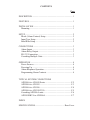
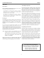
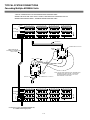
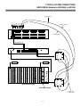
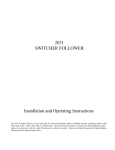
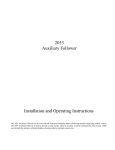
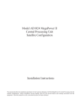
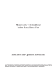
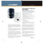
Model AD2096A
Alarm Interface Unit
Installation and Operating Instructions
This manual describes the installation and operating procedures for the American Dynamics AD2096A Alarm Interface Unit.
The AD2096A Alarm Interface Unit, when used with American Dynamics Matrix Switching Systems, automatically calls
specified cameras and preset scenes to specified monitors when contacts are activated external to the system.
-
The software/firmware furnished with this equipment is confidential to and is copyrighted by SENSORMATIC ELECTRONICS
CORPORATION. It is not to be copied or disclosed in any manner without the express written consent of SENSORMATIC. The
software/firmware is furnished to the purchaser under a license for use on a single system.
Information furnished by SENSORMATIC is believed to be accurate and reliable. However, no responsibility is assumed by
SENSORMATIC for its use; nor for any infringements of other rights of third parties which may result from its use. No license is
granted by implications or otherwise under any patent or patent rights of SENSORMATIC.
Copyright 2000 by Sensormatic. All rights reserved.
AMERICAN
DYNAMICS
The installation of this product should be made by qualified
service personnel and should conform to all local codes.
CAUTION
RISK OF ELECTRIC SHOCK
DO NOT OPEN
The lightning flash with arrowhead
symbol, within an equilateral
triangle, is intended to alert the
user to the presence of uninsulated
"dangerous voltage" within the
product's enclosure that may be of
sufficient magnitude to constitute a
risk of electric shock to persons.
!
CAUTION: TO REDUCE THE RISK OF ELECTRIC SHOCK,
DO NOT REMOVE COVERS (OR BACK) .
NO USER-SERVICEABLE PARTS INSIDE.
REFER SERVICING TO QUALIFIED SERVICE PERSONNEL
WARNING
!
The exclamation point within an
equilateral triangle is intended to
alert the user to the presence of
important operating and maintenance
(servicing) instructions in the
literature accompanying the product.
UNPACKING AND INSPECTION
To reduce the risk of fire or shock hazard, do
not expose this product to rain or moisture.
Unpack carefully. This is an electronic product and should
be handled as such. Compare the items received with the
packing list with your order.
This equipment has been tested and
found to comply with Part 15 of the
FCC Rules.
Be sure to save:
1. The shipping cartons and insert pieces. They are the
safest material in which to make future shipments of
the product.
2. The IMPORTANT SAFEGUARDS sheet.
3. These Installation and Operating Instructions.
Operation is subject to the
following two conditions: 1. This
device may not cause harmful
interference, and 2. This device
must accept any interference
received, including interference
that may cause undesired operation.
)
MAINTENANCE
User maintenance of this unit is limited to external cleaning
and inspection. For specific recommendations refer to the
IMPORTANT SAFEGUARDS sheet packaged with this product.
INSTALLATION AND SERVICE
If you require information during installation of this
product or if service seems necessary, contact the
Sensormatic Repair and Service Department at (800)
442-2225. You must obtain a Return Authorization Number
and shipping instructions before returning any product for
service.
Do not attempt to service this product yourself. Opening or
removing covers may expose you to dangerous voltages or
other hazards. Refer all servicing to qualified personnel.
QA301D
CONTENTS
Page
DESCRIPTION .............................................................................. 1
FEATURES .................................................................................... 1
INSTALLATION............................................................................ 1
Mounting.................................................................................... 1
SETUP ............................................................................................ 2
Block (Alarm Contact) Setup .................................................... 2
Input Type Setup........................................................................ 2
Baud Rate Setup ........................................................................ 2
CONNECTIONS ............................................................................ 3
Alarm Inputs .............................................................................. 3
Alarm Relay Output................................................................... 3
RS-232 Connection.................................................................... 3
Cascading Multiple Units .......................................................... 3
OPERATION .................................................................................. 4
Power Sources ........................................................................... 4
Powering Up .............................................................................. 4
Alarm Response Operation........................................................ 4
Programming Alarm Contacts ................................................... 4
TYPICAL SYSTEM CONNECTIONS
AD2096A to AD1650 Series ................................................. C-2
AD2096A to AD1995............................................................ C-3
AD2096A to AD1996............................................................ C-4
AD2096A to AD2150/2350................................................... C-5
Cascading AD2096A units .................................................... C-6
AD2010DBVL to AD2096A ................................................. C-7
INDEX
SPECIFICATIONS......................................................... Rear Cover
AD2096A
ALARM INTERFACE UNIT
SELECT
ABCDEFGH
POWER
ALARM
ABCDEFGH
1
A
A
25
26
A
49
C
O
M
INPUT
OUTPUT
2
A
A
50
A
3
4
A
A
27
A
A
28
A
51
A
5
52
A
A
A
30
31
32 33 34 35
A
A
55
56 57 58 59
A
53
A
7
A
29
A
6
54
A
A
8
A
9
A
A
A
10
A
A
A
11 12
A
A
A
A
36
A
60
A
13
14 15 16 17
A
A
37
38 39 40 41
A
A
61
62 63 64
A
A
A
A
A
A
A
A
A
18
19
A
42
A
20
21
22
23
A
A
A
A
A
43
44
45
46
47
A
A
A
A
A
24
A
48
A
120V
60Hz
A
N N C
O C M
Figure 1 - AD2096A Alarm Interface Unit Rear Panel
DESCRIPTION
Mounting
The AD2096A Alarm Interface Unit (AIU) is used with
American Dynamics Matrix Switching Systems to provide
automatic callup of a camera to a monitor when a specific
alarm switch/contact input is activated. Each AD2096A AIU
is set up to identify the matrix system video input and preset
scenes with which it will be associated. The AD2096A has the
capability to respond to 64 alarm inputs. The number of alarm
inputs can be increased by cascading multiple AD2096A units.
The AD2096A cabinet may be surface or rack mounted in any
convenient location with adequate ventilation. See Figure 2
for illustration of the mounting options.
• The AD2096A is shipped with mounting ears installed flush
with the front panel, and can be mounted to the front of a
standard 19" rack.
• The ears of the AD2096A can be removed and placed such
that they are flush with the rear panel. This allows the
AD2096A to be mounted to the rear of a rack that is
equipped with mounting channels.
FEATURES
• UNIVERSAL MOUNT CABINET
• LED POWER INDICATOR ON REAR PANEL
• The AD2096A can be mounted to the wall by installing the
ears perpendicular the sides of the unit. The bottom or top
covers can face toward the wall and the front or rear panel
face upwards.
• LED ALARM INDICATOR ON REAR PANEL
• DIP SWITCH SELECTION TO SET BAUD RATE
• DIP SWITCH SELECTION FOR CAMERA GROUP
• DIP SWITCH SELECTION TO ACCEPT NORMALLY
OPEN OR NORMALLY CLOSED INPUTS
The AD2096A AIU is two rack units in height (3.5") and one
unit wide (19"). For proper ventilation allow at least three feet
(1m) from the rear of the racks to any wall and one EIA rack
height (1 3/4"/4.5cm) between units.
• SCREW TERMINAL WIRE CONNECTORS
• TERMINALS AVAILABLE TO ACTIVATE VCR OR
OTHER DEVICES
A
A
AA
A
A
AA
AA
RA CK CHA NNEL
INSTALLATION
This installation should be made by qualified service personnel
and should conform to all local codes. Safeguards must be
taken to avoid unintentional operation by employees and
maintenance personnel working about the premises, by falling
objects, by customers, by building vibration, and by similar
causes.
TOP COVER
FRONT OR REAR PANEL
A
A
A
A
A
WA LL
FRONT OR REAR PANEL
TOP OR BOTTOM COVER
MOUNTING EARS
Figure 2 - Mounting Options
1
ALARM INTERFACE UNIT
AD2096A
SETUP
Table 2 - S2, Input Type Setup
0 = OFF (Normally Open, NO)
1 = ON (Normally Closed, NC)
Three 8-position DIP switches are used for AD2096A setup.
The first two switches, S1 and S2, are located on the rear panel
(see Figure 1, page 1). The top switch, S1, identifies the block
of 64 alarm contacts (out of a possible 1024) which are
connected to the AD2096A. The lower switch, S2, configures
the AD2096A for either Normally Open (NO) or Normally
Closed (NC) alarm contacts within each group of eight inputs
of the selected block. Each group may be set to a different
input type. The third switch, S3, is located internally on the
AD2096A PC board (see Figure 3), and is used to select the
RS-232 COM ports baud rates.
ALARM
INPUT #s
1-8
9 - 16
17 - 24
25 - 32
33 - 40
41 - 48
49 - 56
57 - 64
Tables 1, 2, and 3 show the switch settings which correspond
to each DIP switch. A user fill-in block is provided under each
table for the installer to record the switch settings.
A
0
0
0
0
0
0
0
0
0
0
0
0
0
0
0
0
SWITCH POSITIONS
B C D E F G
0 0 0 0 0 0
0 0 0 0 0 0
0 0 0 0 0 1
0 0 0 0 0 1
0 0 0 0 1 0
0 0 0 0 1 0
0 0 0 0 1 1
0 0 0 0 1 1
0 0 0 1 0 0
0 0 0 1 0 0
0 0 0 1 0 1
0 0 0 1 0 1
0 0 0 1 1 0
0 0 0 1 1 0
0 0 0 1 1 1
0 0 0 1 1 1
ALARM INPUT
CONFIGURATION
H
0
1
0
1
0
1
0
1
0
1
0
1
0
1
0
1
!
A
B C
D
E
F
G
H
CAUTION - Due to the presence of noninsulated components with hazardous
voltages, the following internal adjustments
should be performed by qualified service
personnel only.
The baud rate of the two COM ports (INPUT and OUTPUT) is
factory set at 1200. Verify the baud rate of the system being
connected to the AD2096A by referring to the applicable
system installation and operation manual. To change the baud
rate of either port, select the correct DIP switch position by
referring to Table 3 below. The two COM ports may be set to
different baud rates, as indicated in the table.
Table 3 - S3, Baud Rate Setup
0 = OFF, 1 = ON
SWITCH POSITIONS
COM INPUT
COM OUTPUT
1 2 3 4
5 6 7 8
0 0 0 0
0 0 0 0
0 0 0 1
0 0 0 1
0 0 1 0
0 0 1 0
0 0 1 1
0 0 1 1
0 1 0 0
0 1 0 0
0 1 0 1
0 1 0 1
0 1 1 0
0 1 1 0
INSTALLERS NOTES - TABLE 1
BAUD
RATE
300
600
1200
2400
4800
9600
19200
CAMERA BLOCK
INSTALLER'S NOTES - TABLE 3
8
1
O N O FF
ALARM INPUT STATE
NO
NC
0
1
0
1
0
1
0
1
0
1
0
1
0
1
0
1
INSTALLERS NOTES - TABLE 2
Table 1 - S1, Block Setup
0 = OFF, 1 = ON
ALARM INPUT
BLOCK CAMERAS
1
1 - 64
2
65 - 128
3
129 - 192
4
193 - 256
5
257 - 320
6
321 - 384
7
385 - 448
8
449 - 512
9
513 - 576
10
577 - 640
11
641 - 704
12
705 - 768
13
769 - 832
14
833 - 896
15
897 - 960
16
961 - 1024
SWITCH
POSITION
H
G
F
E
D
C
B
A
Dip Switch
BAUD RATE
IN
OUT
Power Cord
Figure 3 - AD2096A PCB Layout
2
AD2096A
ALARM INTERFACE UNIT
CONNECTIONS
Use NEC Class 2 wiring only for all external
connector pin connections. The wiring should also
conform to all local codes.
!
RS-232 Connectors
Alarm Inputs
The two RS-232 COM connectors on the rear panel of the
AD2096A are 8-pin, modular type RJ-45 connectors. One (1)
8-pin terminal box 2113-0019-01 and one (1) 7-foot modular
cable 6003-0047-02 are supplied with each AD096A for
connections to these ports.
Eleven 12-pin connectors are provided on the rear panel of the
AD2096A for alarm inputs. A mating screw-terminal
connector, below, is supplied for each rear panel connector.
HOLD DOWN SCREWS
The RS-232 port labeled COM OUTPUT is connected to a
switching system input port or to another AD2096A AIU (see
Cascading, below) using the supplied modular cable when
distances between the units are no further than 7' apart.
A
A
For connection where distances exceed 7', or for connection to
an AD1995 MegaPower CPU, the terminal box is used. Table
4 gives the pinouts for the terminal box. The maximum
distance between terminal boxes shall not exceed 1000' (330m)
using 18 AWG shielded cable, Belden 8770 or equivalent.
A
A
A
A
R
TO
EC
N
ON
N
TC
TIO
ER
S
EC
R
IN
I
D
IS
TH
Figure 4 - Alarm Input Terminal Connector
Table 4 - RS-232 Terminal Box Pinouts
Each connector is labeled with an alarm number (1 - 64), an
"A", and a ground symbol. The "A" stands for alarm contact
and the ground symbol for ground. Each alarm input connector
contact open circuit voltage is 5.0 VDC. Closed circuit current
is 0.2 mA, and a normally closed condition requires less than
15K ohms between “A” and ground.
Function
No Connection
Shield
No Connection
RCD
XMIT
No Connection
GND
No Connection
Pin
1
2
3
4
5
6
7
8
Connections are made by inserting alarm contact and ground
wires into the slots of the mating connectors and tightening the
hold down screws. When all wires have been connected, insert
the 12-pin connectors into the rear panel connectors.
Alarm Relay Output
The lower right connector on the rear of the AD2096A is a 12pin connector which provides access to both Normally-Open
(NO) and Normally-Closed (NC) contacts of an internal alarm
relay. This relay is active when any alarm input is received
(see page 4). The maximum relay contact ratings are: 0.25
amps current @ 30 Volts DC or RMS, and 10 VA power. A
mating screw-terminal connector is provided.
4
HOLD DOWN SCREWS
5
3
6
2
7
1
8
Figure 6 - Terminal Box 2113-0019-01
Cascading Multiple Units
N
O N
C
If more than 64 alarm contacts are required, multiple
AD2096A units can be cascaded. If the units are within 7' of
the other, connect a modular cable from the COM OUTPUT
port of the last AD2096A unit to the COM INPUT port of the
next unit. If the AD2096A units are greater than 7' apart,
terminal boxes must be used for port connections. Refer to the
Typical System Connection for illustration of cascading.
C
M
OR
CT
NE
N
O
N
TC
TIO
ER
S
EC
R
IN
I
D
IS
TH
Figure 5 - Alarm Relay Terminal Connector
3
ALARM INTERFACE UNIT
AD2096A
OPERATION
Alarm Response Operation
Power Sources
Each alarm input signal is assigned an alarm contact number
(ACN) by the AD2096A. The setting of DIP switch S1 (see
page 2) determines the range of ACN’s for each AD2096A.
Depending on the Matrix Switching System capabilities, a
maximum of 1024 alarm contacts (ACN’s) can be programmed
for alarm event response by that system.
Power is supplied via the appended 3-wire power cord. Power
consumption is approximately eight watts.
The AD2096A is configured for 120VAC, 50/60Hz,
primary power source. Operating power voltages must be
held within the 105V and 125V range.
When an alarm condition exists, the AD2096A AIU detects the
closure (or opening) of the contact, depending on the DIP
switch configuration (S2, page 2). The AD2096A AIU then
issues an alarm message containing the corresponding alarm
contact number (ACN), via the RS-232 COM OUTPUT Port,
to the Matrix Switching System for camera callup to monitors.
The AD2096-1 is configured for a 230VAC, 50/60 Hz
primary power source. Operating power voltages must be
held within the 198V and 250V range.
Powering Up
The AD2096A AIU does not contain a power On/Off switch.
A green POWER LED indicator, located on the rear panel,
illuminates when power is applied. If an alarm input is
activated, the green ALARM LED on the rear panel will
illuminate.
When an alarm contact is detected, the AD2096A AIU also
activates an internal relay, providing both an output closure
(NO pin) and an opening (NC pin); this relay output can be
used to turn on/off lights, VCRs, etc. The alarm relay output
continues to be active until the alarm condition is removed.
Once the alarm condition is deactivated (contact is cleared),
the alarm relay is held for 10 seconds, then is deactivated.
The 120 VAC units are supplied with a pendant 3-wire cord
and plug for mating to the primary source outlet. The 230 VAC
units are supplied with a Euro-style IEC 320 type inlet. A
suitable, detachable cord should be connected between the IEC
320 inlet and power source. The cord should conform to all
national and local use code requirements.
Programming Alarm Contacts
Each alarm contact (ACN) input to an AD Matrix Switching
System is armed for camera callup on a specific monitor.
Individual camera inputs and camera salvos, each with preset
scenes and auxiliary actions, may be programmed for
automatic callup to monitors in response to alarm inputs.
Note: DO NOT CONNECT THE EQUIPMENT TO THE
POWER SOURCE UNTIL READY TO POWER UP.
THE SOCKET OUTLET SHALL BE LOCATED
NEAR THE EQUIPMENT, AND SHALL BE
READILY ACCESSIBLE.
When the switching system is armed for alarm contact (ACN)
inputs, the video input associated with the ACN is
automatically displayed when that alarm input is detected by
the AD2096A AIU and sent to the switching system. Refer to
the Alarm Programming sections in the appropriate Matrix
Switching System Installation Manual for the commands to
arm alarm contacts, monitors, and cameras.
Make all connections to the AD2096A Alarm Inputs and
Output Relay connections and set the DIP switches as
indicated on page 2 before applying power to the AD2096A.
IF YOU ENCOUNTER ANY PROBLEMS
OPERATING THIS UNIT, OR NEED ASSISTANCE,
CALL OUR TECHNICAL SUPPORT CENTER:
within the United States 1-800-442-2225
outside the United States (845) 624-7640
4
Typical System Connections
TYPICAL SYSTEM CONNECTIONS
AD2096A TO AD1650 Series
TYPICAL AD2096A CONNECTIONS TO AD1650 SWITCHERS:
WHEN THE UNITS ARE LESS THAN 7' APART, USE CABLE 6003-0047-02
WHEN DISTANCES EXCEED 7', TERMINAL BOXES MUST BE USED
NORMALLY OPEN/CLOSED
POSITION FOR ALARM INPUTS
1-8, 9-16, 17-24 etc...
1
SELECTS ALARM GROUP #
1-64, 65-128, 129-192 etc....
2
A
3
A
4
A
A
SELECT
POWER
ALARM
ON
OFF
ABCDEFGH
ON
OFF
ABCDEFGH
C
O
M
7
A
A
A
A
A
5
A
A
6
A
8
A
9 10 11 12
A
A
A
A
A
13 14 15 16 17 18
19 20 21 22 23 24
A
A
A
A
A
A
A
A
A
A
A
A
25 26 27 28 29 30
31 32 33 34 35 36
37 38 39 40 41 42
43 44 45 46 47 48
A
A
A
A
A
A
A
A
A
A
A
A
A
A
A
A
49 50 51 52 53 54
55 56 57 58 59 60
61 62 63 64
A
A
A
A
A
A
A
A
A
N N C
O C M
A
A
A
A
120V
60Hz
MW
INPUT
A
A
A
A
A
A
A
A
A
A
A
A
A
OUTPUT
AD2096A
6003-0047-02
TERMINAL BOX 2113-0019-01
BROWN
(GRD)
1
8
2
CABLE 6003-0047-02
FOR DIRECT CONNECTIONS
UP TO 7 FEET
7
6
3
5
RED
4
RED
GREEN
GREEN
4
3
2
1
5
6
NOTE: FOR DISTANCES GREATER THAN 7' BETWEEN UNITS,
TERMINAL BOXES MUST BE USED. THE MAXIMUM
DISTANCE BETWEEN THE BOXES IS 1000' (330m)
USING SHIELDED, 18 AWG CABLE.
7
8
BROWN
(GRD)
6003-0047-02
TERMINAL BOX 2113-0019-01
RS-232
PGM MON
1
2
K
E
Y
B
R
D
MONITOR
8
1
MONITOR
7
6
MONITOR
5
4
MONITOR
3
2
1
A
A
A
A
A
A
A
A
B
B
B
B
B
B
B
B
O
U
T
O
U
T
O
U
T
O
U
T
O
U
T
O
U
T
O
U
T
O
U
T
2
3
4
3
4
J1
OUT
5
6
7
8
AD1650/1650A/1650B
C-2
TYPICAL SYSTEM CONNECTIONS
AD2096A TO AD1995
FOR ALL CONNECTIONS TO AD1995 CPU, TERMINAL BOXES MUST BE USED.
THE MAXIMUM DISTANCE BETWEEN THE BOX AND THE AD1995 CONNECTOR
IS 1000' (330m) USING SHIELDED, 18 AWG CABLE.
NORMALLY OPEN/CLOSED
POSITION FOR ALARM INPUTS
1-8, 9-16, 17-24 etc...
1
SELECTS ALARM GROUP #
1-64, 65-128, 129-192 etc....
2
A
A
3
4
A
A
SELECT
POWER
ALARM
ON
OFF
ABCDEFGH
ON
OFF
ABCDEFGH
C
O
M
INPUT
7
A
A
A
A
A
A
A
25 26 27 28 29 30
A
A
A
A
A
5
A
8
A
6
A
9 10 11 12
A
A
A
A
A
31 32 33 34 35 36
A
A
A
A
A
A
A
55 56 57 58 59 60
A
A
A
A
A
A
A
A
A
A
A
A
A
A
A
A
37 38 39 40 41 42
A
49 50 51 52 53 54
A
13 14 15 16 17 18
A
A
A
A
A
A
A
19 20 21 22 23 24
A
A
A
A
A
A
61 62 63 64
A
A
A
A
OUTPUT
A
A
A
43 44 45 46 47 48
A
A
A
120V
60Hz
N N C
O C M
AD2096A
AUX START RELAY OUTPUT
6003-0047-02
TERMINAL BOX 2113-0019-01
BROWN
(GRD)
8
1
7
2
GREEN
6
3
5
1
2
6
RST
PORT
10
LAN
1
PORT
9
IN
OUT
PORT
8
3
7
4
8
RED
4
5
9
LAN
2
PORT
7
IN
OUT
PORT
6
PORT
1
PORT
5
PORT
2
PORT
4
PORT
3
AD1995
C-3
TYPICAL SYSTEM CONNECTIONS
AD2096A TO AD1996
TYPICAL AD2096A CONNECTIONS TO AD1996 CPU:
WHEN THE UNITS ARE LESS THAN 7' APART, USE CABLE 6003-0047-02
WHEN DISTANCES EXCEED 7', TERMINAL BOXES MUST BE USED
NORMALLY OPEN/CLOSED
POSITION FOR ALARM INPUTS
1-8, 9-16, 17-24 etc...
1
2
3
4
5
6
SELECTS ALARM GROUP #
1-64, 65-128, 129-192 etc....
A
A
A
A
SELECT
POWER
ALARM
ON
OFF
ABCDEFGH
ON
OFF
ABCDEFGH
C
O
M
INPUT OUTPUT
7
A
A
A
A
A
A
A
25 26 27 28 29 30
A
A
A
A
A
A
8
A
A
9 10 11 12
A
A
A
A
A
A
A
A
A
A
A
A
A
A
A
A
A
A
A
A
A
A
A
19 20 21 22 23 24
A
A
37 38 39 40 41 42
A
55 56 57 58 59 60
A
A
31 32 33 34 35 36
49 50 51 52 53 54
A
13 14 15 16 17 18
A
A
A
A
A
A
A
A
A
A
A
A
A
A
A
61 62 63 64
A
A
A
A
A
A
A
43 44 45 46 47 48
A
A
120V
60Hz
N N C
O C M
AD2096A
AUX START RELAY OUTPUT
6003-0047-02
TERMINAL BOX 2113-0019-01
BROWN
(GRD)
1
8
2
7
6
3
5
CABLE 6003-0047-02
FOR DIRECT CONNECTIONS
UP TO 7 FEET
RED
4
RED
GREEN
GREEN
4
5
3
6
NOTE: FOR DISTANCES GREATER THAN 7' BETWEEN UNITS,
TERMINAL BOXES MUST BE USED. THE MAXIMUM
DISTANCE BETWEEN THE BOXES IS 1000' (330m)
USING SHIELDED, 18 AWG CABLE.
7
2
1
8
BROWN
(GRD)
6003-0047-02
TERMINAL BOX 2113-0019-01
DATA LINE
PROG MON
PORTS
120V
60Hz
1
2
1
2
3
4
5
6
7
8
9
10
AD1996
C-4
TYPICAL SYSTEM CONNECTIONS
AD2096A TO AD2150/2350
TYPICAL AD2096A CONNECTIONS TO AD2150/2350 SWITCHERS:
WHEN THE UNITS ARE LESS THAN 7' APART, USE CABLE 6003-0047-02
WHEN DISTANCES EXCEED 7', TERMINAL BOXES MUST BE USED
NORMALLY OPEN/CLOSED
POSITION FOR ALARM INPUTS
1-8, 9-16, 17-24 etc...
1
SELECTS ALARM GROUP #
1-64, 65-128, 129-192 etc....
2
A
SELECT
3
A
1
2
3
4
5
A
A
A
A
A
4
A
5
A
6
7
A
8
6
A
9 10 11 12
13 14 15 16 17 18
19 20 21 22 23 24
ON
OFF
ABCDEFGH
POWER
A
A
25 26 27 28 29 30
ALARM
A
A
A
A
A
A
31 32 33 34 35 36
A
A
A
A
A
A
A
A
A
A
A
37 38 39 40 41 42
43 44 45 46 47 48
A
A
ON
OFF
ABCDEFGH
A
C
O
M
INPUT
OUTPUT
A
A
A
A
A
A
A
A
A
A
A
A
A
A
49 50 51 52 53 54
55 56 57 58 59 60
61 62 63 64
A
A
A
A
A
A
A
A
A
A
A
A
A
A
A
A
A
A
A
A
A
A
A
A
A
120V
60Hz
N N C
O C M
AD2096A
6003-0047-02
TERMINAL BOX 2113-0019-01
BROWN
(GRD)
1
8
2
7
6
3
5
CABLE 6003-0047-02
FOR DIRECT CONNECTIONS
UP TO 7 FEET
RED
4
RED
GREEN
GREEN
2113-0019-01
TERMINAL BOX
4
3
5
6
NOTE: FOR DISTANCES GREATER THAN 7' BETWEEN UNITS,
TERMINAL BOXES MUST BE USED. THE MAXIMUM
DISTANCE BETWEEN THE BOXES IS 1000' (330m)
USING SHIELDED, 18 AWG CABLE.
7
2
1
8
BROWN
(GRD)
6003-0047-02
ALARMS
RELAY
CODE
CAMERAS
1
2
3
4
5
6
7
8
9
10
11
12
13
14
15
16
17
18
19
20
21
22
23
24
25
26
27
28
29
30
32
BWS BWS BWS BWS
MONITORS
31
120V
60Hz
1
2
1
3
4
2
5
3
KEYBOARDS
2
3
4
5
RS232 PORTS
AD2150/2350
C-5
TYPICAL SYSTEM CONNECTIONS
Cascading Multiple AD2096A Units
TYPICAL CONNECTIONS TO CASCADE MULTIPLE AD2096A UNITS:
WHEN THE UNITS ARE LESS THAN 7' APART, USE MODULAR CABLE 6003-0047-02
WHEN DISTANCES EXCEED 7', TERMINAL BOXES MUST BE USED
SELECT
1
2
3
4
5
A
A
A
A
A
6
7
8
9 10 11 12
13 14 15 16 17 18
19 20 21 22 23 24
ON
OFF
ABCDEFGH
POWER
A
A
25 26 27 28 29 30
ALARM
A
A
A
A
A
31 32 33 34 35 36
A
A
A
A
A
A
A
A
A
A
A
A
37 38 39 40 41 42
43 44 45 46 47 48
A
A
ON
OFF
ABCDEFGH
C
O
M
INPUT
OUTPUT
A
A
A
A
A
A
A
A
A
A
A
A
A
A
A
49 50 51 52 53 54
55 56 57 58 59 60
61 62 63 64
A
A
A
A
A
A
A
A
A
A
A
A
A
A
A
A
A
A
A
A
A
A
A
A
A
120V
60Hz
N N C
O C M
AD2096A
6003-0047-02
TERMINAL BOX 2113-0019-01
BROWN
(GRD)
CABLE 6003-0047-02
FOR DIRECT CONNECTIONS
UP TO 7 FEET
8
1
2
7
6
3
4
5
RED
RED
GREEN
GREEN
4
3
2
1
5
6
7
8
BROWN
(GRD)
TERMINAL BOX 2113-0019-01
6003-0047-02
SELECT
1
2
3
4
5
A
A
A
A
A
6
7
8
9 10 11 12
NOTE: FOR DISTANCES GREATER THAN 7' BETWEEN UNITS,
TERMINAL BOXES MUST BE USED. THE MAXIMUM
DISTANCE BETWEEN THE BOXES IS 1000' (330m)
USING SHIELDED, 18 AWG CABLE.
13 14 15 16 17 18
19 20 21 22 23 24
ON
OFF
ABCDEFGH
POWER
A
25 26 27 28 29 30
ALARM
A
A
A
A
A
A
31 32 33 34 35 36
A
A
A
A
A
A
A
A
A
A
A
A
37 38 39 40 41 42
43 44 45 46 47 48
A
A
ON
OFF
ABCDEFGH
C
O
M
INPUT
OUTPUT
A
A
A
A
A
A
A
A
A
A
A
A
A
A
A
49 50 51 52 53 54
55 56 57 58 59 60
61 62 63 64
A
A
A
A
A
A
A
A
A
A
A
A
A
A
A
A
A
A
A
A
A
A
A
A
A
120V
60Hz
N N C
O C M
AD2096A
Connection to next cascaded AD2096A AIU,
or to Matrix Switching System
C-6
TYPICAL SYSTEM CONNECTIONS
AD2010DBVL Module to AD2096A to AD1996
18-AWG CABLE
1
2
3
A
A
A
SELECT
ABCDEFGH
1 2
A
4
5
A
A
3
4
5
A A
A
A
6
ALARM CONTACT
A
6
A
7
8
9
10 11 12
A
A
A
A
A
13 14 15 16 17 18
A
A
A
A
A
A
19 20 21 22 23 24
A
A
POWER
25 26 27 28 29 30
31 32 33 34 35 36
A
A
A
A
A
37 38 39 40 41 42
43 44 45 46 47 48
A
A
ALARM
ABCDEFGH
C
O
M
INPUT
OUTPUT
A
A
A
A
A
A
A
A A
A
A
A
A
A
A
A
49 50 51 52 53 54
55 56 57 58 59 60
61 62 63 64
A
A
A
A
A
A
A
A
A
A
A
A
A
A
A
A
A
A
A
A
ALARM GROUND
A
120V
60Hz
A
N N C
O C M
AD2096A
CABLE 6003-0047-02
DATA LINE
PORTS
PROG MON
120V
60Hz
1
1
2
2
3
4
5
6
7
8
9
10
1
AD1996
2
3
4
5
8
241
241
225
209
193
7
6
1
177
161
145
129
113
97
81
65
49
33
17
1
1
5
9
IN
DATA LINE
OUT
IN
SYNC
OUT
1
3
120 VAC
50/60 Hz
1
2
3
4
5
AD2010 Switching Bay
8
7
6
AD2010DBVL Module
SHIELDED,
18-AWG CABLE
C-7
Index
INDEX
AD2096A
Alarm Input Connections . . . . . . . . . . . . . . . . . . . . . . . . . . 3
Alarm Relay Output Connection . . . . . . . . . . . . . . . . . . . . . 3
Alarm Response Operation . . . . . . . . . . . . . . . . . . . . . . . . . 4
Baud Rate Setup . . . . . . . . . . . . . . . . . . . . . . . . . . . . . . . . . 2
Block Setup . . . . . . . . . . . . . . . . . . . . . . . . . . . . . . . . . . . . . 2
Cascading Multiple Units . . . . . . . . . . . . . . . . . . . . . . . . . . 3
CONNECTIONS
Alarm Input Connections . . . . . . . . . . . . . . . . . . . . . . . 3
Alarm Relay Output . . . . . . . . . . . . . . . . . . . . . . . . . . . 3
Cascading Multiple Units . . . . . . . . . . . . . . . . . . . . . . 3
RS-232 Connections . . . . . . . . . . . . . . . . . . . . . . . . . . 3
DESCRIPTION . . . . . . . . . . . . . . . . . . . . . . . . . . . . . . . . . . 1
FEATURES . . . . . . . . . . . . . . . . . . . . . . . . . . . . . . . . . . . . 1
Input Type Setup . . . . . . . . . . . . . . . . . . . . . . . . . . . . . . . . . 2
INSTALLATION . . . . . . . . . . . . . . . . . . . . . . . . . . . . . . . . 1
OPERATION
Alarm Response . . . . . . . . . . . . . . . . . . . . . . . . . . . . . . 4
Power Sources . . . . . . . . . . . . . . . . . . . . . . . . . . . . . . . 4
Powering Up . . . . . . . . . . . . . . . . . . . . . . . . . . . . . . . . 4
Programming Alarm Contacts . . . . . . . . . . . . . . . . . . . 4
Power Sources . . . . . . . . . . . . . . . . . . . . . . . . . . . . . . . . . . . 4
Powering Up . . . . . . . . . . . . . . . . . . . . . . . . . . . . . . . . . . . . 4
Programming Alarm Contacts . . . . . . . . . . . . . . . . . . . . . . 4
Rack mounting . . . . . . . . . . . . . . . . . . . . . . . . . . . . . . . . . . 1
RS-232 Connections . . . . . . . . . . . . . . . . . . . . . . . . . . . . . . 3
SETUP
Baud Rate Setup . . . . . . . . . . . . . . . . . . . . . . . . . . . . . . 2
Block Setup . . . . . . . . . . . . . . . . . . . . . . . . . . . . . . . . . 2
Input Type Setup . . . . . . . . . . . . . . . . . . . . . . . . . . . . . 2
SPECIFICATIONS . . . . . . . . . . . . . . . . . . . . . . . Rear Cover
Wall mounting . . . . . . . . . . . . . . . . . . . . . . . . . . . . . . . . . . . 1
I-2
DECLARATION OF CONFORMITY
According to ISO/IEC Guide 22 and EN45014
Manufacturer’s Name:
Sensormatic Electronics Corporation
Manufacturer’s Address:
1 Blue Hill Plaza
2nd Floor
Pearl River, New York, 10965 USA
Declares, that the product listed below:
Name/Type:
Alarm Interface Unit
Model Number:
AD2096-1
complies with all applicable directives as demonstrated by conformance to the following Product Specifications:
Safety:
EN 60950: 1992
EMC:
EN 50130-4: 1995
EN 55022: 1994 , Class B
EN 61000-3-2: 1995
EN 61000-3-3: 1995
EN 61000-4-2: 1995
EN 61000-4-3: 1996
EN 61000-4-4: 1995
EN 61000-4-5: 1995
EN 61000-4-6: 1996
EN 61000-4-11: 1994
Supplementary Information:
The products herewith comply with the requirements of the Low Voltage Directive, 73/23/EEC as amended by
93/68/EEC, and the EMC Directive, 89/339/EEC as amended by 93/68/EEC.
Pearl River, NY, USA
15 December, 2000
Harold D. Johnson, Ph.D.
Director of Engineering
European Contact: Sensormatic France S.A.
7, rue Alexis de Tocqueville, Parc de Haute Technologie, 92183 ANTONY CEDEX
SPECIFICATIONS
Models
AD2096A: 120 VAC, 50/60 Hz
AD2096-1: 230 VAC, 50/60 Hz
Electrical
Input: AD2096A
AD2096-1
- 120 VAC, 50/60Hz, 8 W
- 230 VAC, 50/60 Hz, 40 mA
Alarm Inputs
Contact Inputs: 64 inputs, each with contact and separate ground
Open Circuit Voltage: 5.0 VDC
Closed Circuit: Maximum Current: 0.2 mA, Maximum Resistance to Ground: 15K Ohms
Auxiliary Output Relay
Relay Outputs:
Power Rating:
Voltage Rating:
Current Rating:
Separate Normally Open (NO) and Normally Closed (NC) contacts
10 VA
30 Volts DC or RMS
0.25 amps
Mechanical
Mounting:
Dimensions:
Weight:
Finish:
Desktop or rack mount
3.5" H x 8" D x 17" W (89mm x 203mm x 432mm)
7 lbs. (3.2 Kg)
Dark Shadow Gray
Sensormatic Video Systems Division
One Blue Hill Plaza
Pearl River, New York 10965
(845) 624-7600
Technical Support Center: 1-800-442-2225
FAX: 845-624-7685
8000-1819-01, Rev A
December, 2000
Printed in USA