1
PS360/360WB Tandem Gas Ovens: English
A MIDDLEBY COMPANY
owner's
operating
& installation
manual
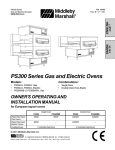
SERIES PS360/360WB
TANDEM GAS OVEN MODELS
PS360L/PS360WB-L Tandem
PS360/PS360WB Double Tandem
PS360U/PS360WB-U Tri Tandem
© 1998 Middleby Marshall Inc.
PS360U/PS360WB-U Quad Tandem
Part No. 38615
Price US $30.00
R. Aug. 98, Rev. B, Ver. 3
NOTICE:
This Operating and Installation Manual should be given to the user. The operator of the oven should be
familiar with the functions and operation of the oven.
This manual must be kept in a prominent, easily reachable location near the oven.
The oven has a combustion system suitable for use with all natural gases and can be converted by a
qualified service agent for use with liquified gas.
It is suggested to obtain a service contract with a manufacturer's certified service agent.
WARNING
POST, IN A PROMINENT LOCATION, THE EMERGENCY TELEPHONE NUMBER OF YOUR LOCAL GAS
SUPPLIER AND INSTRUCTIONS TO BE FOLLOWED IN THE EVENT YOU SMELL GAS.
Instructions to be followed in the event the user smells gas shall be obtained by consulting the local gas
supplier. If the smell of gas is detected, immediately call the emergency phone number of your local Gas
Company. They will have personnel and provisions available to correct the problem.
FOR YOUR SAFETY
Do not store or use gasoline or other
flammable vapors or liquids in the
vicinity of this or any other appliance.
WARNING:
Improper installation, adjustment, alteration, service or
maintenance can cause property damage, injury or
death. Read the installation, operating and maintenance
instructions thoroughly before installing or servicing
this equipment.
NOTICE
CONTACT YOUR LOCAL SERVICE COMPANY TO PERFORM MAINTENANCE AND REPAIRS.
A SERVICE AGENT DIRECTORY IS SUPPLIED IN YOUR INSTALLATION KIT.
NOTICE
Using any parts other than genuine Middleby Marshall factory
manufactured parts relieves the manufacturer of all warranty and liability.
NOTICE
Middleby Marshall (Manufacturer) reserves the right to
change specifications at any time.
NOTICE
The equipment warranty is not valid unless the oven is installed, started and demonstrated under
the supervision of a factory certified installer.
Retain This Manual For Future Reference
i
MIDDLEBY MARSHALL INC.
OVEN LIMITED WARRANTY
(Non U.S.A.)
The seller warrants equipment manufactured by it to be free
from defects in material and workmanship for which it is
responsible. The Sellers obligation under this warranty shall
be limited to replacing or repairing at Sellers option, without
charge, F.O.B. Sellers factory, any part found to be defective
and any labor and material expense incurred by Seller in
repairing or replacing such part, such warranty to be limited to
a period of one year from date of original installation or 15
months from date of shipment from Sellers factory, whichever
is earlier, provided that terms of payment have been fully met.
All labor shall be performed during regular working hours.
Overtime premium will be charged to the Buyer.
This warranty is not valid unless equipment is installed,
started, and demonstrated under the supervision of a
factory certified installer.
Normal maintenance functions, including lubrication, adjustment of airflow, thermostats, door mechanisms, microswitches,
burners and pilot burners and replacement of light bulbs, fuses
and indicating lights, are not covered by warranty.
Any repairs or replacements of defective parts shall be performed by Sellers authorized service personnel. Seller shall
not be responsible for any costs incurred if the work is performed by other than Sellers authorized service personnel.
When returning any part under warranty, the part must be intact
and complete, without evidence of misuse or abuse, freight
prepaid.
Seller shall not be liable for consequential damages of any kind
which occur during the course of installation of equipment, or
which result from the use or misuse by Buyer, its employees or
others of the equipment supplied hereunder, and Buyers sole
and exclusive remedy against Seller for any breach of the
foregoing warranty or otherwise shall be for the repair or
replacement of the equipment or parts thereof affected by such
breach.
The foregoing warranty shall be valid and binding upon Seller
if and only if Buyer loads, operates and maintains the equipment supplied hereunder in accordance with the instruction
manual provided to Buyer. Seller does not guarantee the
process of manufacture by Buyer or the quality of product to be
produced by the equipment supplied hereunder and Seller
shall not be liable for any prospective or lost profits of Buyer.
THE FOREGOING WARRANTY IS EXCLUSIVE AND IN LIEU
OF ALL OTHER EXPRESS AND IMPLIED WARRANTIES
WHATSOEVER. SPECIFICALLY THERE ARE NO IMPLIED
WARRANTIES OF MERCHANTABILITY OR OF FITNESS
FOR A PARTICULAR PURPOSE.
The foregoing shall be Sellers sole and exclusive obligation
and Buyers sole and exclusive remedy for any action, whether
in breach of contract or negligence. In no event shall seller be
liable for a sum in excess of the purchase price of the item.
Middleby Marshall Inc. 1400 Toastmaster Drive Elgin, IL 60120 USA (847) 741-3300 FAX (847) 741-4406
Middleby Corporation 24-hour Service Hotline 1-800-238-8444
www.middleby.com
ii
TABLE OF CONTENTS
page
SECTION 1 - DESCRIPTION
OVEN SPECIFICATION CHARTS ............................ 1-1
CHART OF ORIFICE SIZES, GAS PRESSURES,
NOMINAL INPUT RATINGS & GAS FLOW ....... 1-1
I.
PRINCIPLE OF AIR FLOW ................................. 1-2
A. Heat Transfer And How It Works ................ 1-3
B. Air Fingers ................................................... 1-4
II. COMPONENT FUNCTION ................................. 1-5
A. Conveyor ..................................................... 1-5
B. Gas Burner .................................................. 1-5
C. Front Window .............................................. 1-5
D. Cooling Fans .............................................. 1-6
E. Blower ......................................................... 1-6
F. Air Fingers ................................................... 1-7
SECTION 2 - INSTALLATION
I.
UNLOADING/UNPACKING ................................ 2-1
II. INSTALLATION, PREPARATION & SUPPLY ..... 2-2
III. VENTILATION SYSTEM ...................................... 2-3
INSTALLATION KIT .................................................. 2-4
DIMENSION DRAWINGS ......................................... 2-5
IV. THERMOCOUPLE INSTALLATION .................. 2-11
V. ASSEMBLY ....................................................... 2-13
GAS OVEN ROUGH-IN ........................................... 2-21
VI. ELECTRICAL CONNECTION .......................... 2-22
VII. GAS SUPPLY FOR GAS HEATED OVENS ...... 2-24
VIII. PREPARATION FOR VARIOUS GASES ........... 2-25
IX. CHANGING ORIFICES ..................................... 2-27
X. VOLUMETRIC METHOD .................................. 2-27
XI. VAR. OF RATED SUPPLY PRESSURES ......... 2-28
SECTION 3 - OPERATION
I.
CONTROL FUNCTIONS .................................... 3-1
II. COMPONENT INFORMATION/LOCATION ........ 3-2
A. Door Safety Switch ...................................... 3-2
B. Blower Switch ............................................. 3-2
C. Heat Switch ................................................. 3-2
D. Temperature Controller .............................. 3-2
E. Conveyor Switch ......................................... 3-3
III. STEP BY STEP OPERATION ............................. 3-4
A. Start-Up Procedure ..................................... 3-4
B. Temp. Controller Operation Inst. ................ 3-5
C. Shutdown Procedure ................................ 3-10
D. Products Baked/Cooked in Ovens ........... 3-10
E. Bake Time vs. Bake Temperature ............ 3-11
F. Conveyor Speed (Bake Time) and
Time of Delivery ........................................ 3-12
NOTE
Wiring Diagrams Are Contained In This Manual
And Are Also Located Inside The Control Box Door.
iii
TABLE OF CONTENTS
SECTION 4 - MAINTENANCE
I.
MAINTENANCE - DAILY ..................................... 4-1
A. Exterior ........................................................ 4-1
B. Fans and Grills ........................................... 4-1
C. Conveyor Belts ............................................ 4-2
D. Crumb Pans ............................................... 4-2
E. Window ....................................................... 4-3
II. MAINTENANCE - MONTHLY .............................. 4-4
A. Removing Conveyor From Oven
For Cleaning ............................................... 4-4
B. Air Fingers Disassembly For Cleaning ...... 4-6
C. Air Finger Reassembly ............................... 4-8
D. Checking Conveyor Belt Tension ............. 4-10
E. Conveyor Belt Link Removal ..................... 4-10
F. Conveyor Reinstallation Into Oven ........... 4-12
III. MAINTENANCE - EVERY 3 MONTHS .............. 4-13
A. Cleaning Blower Motors ........................... 4-13
B. Electrical Terminals .................................. 4-13
IV. MAINTENANCE - EVERY 6 MONTHS .............. 4-14
SECTION 5 - TROUBLESHOOTING
OWNERS TROUBLESHOOTING CHARTS .............. 5-1
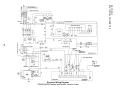
SECTION 6 - ELECTRICAL SCHEMATICS
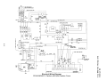
Wiring Diagram Tandem/Double Tandem Ovens ....................... 6-2
Wiring Diagram Tri Tandem/Quad Tandem Ovens ..................... 6-3
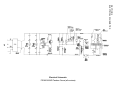
Schematic - PS360/360WB Tandem (All Models) .... 6-4
iv
NOTES:
v
SECTION 1
DESCRIPTION
SECTION 1
DESCRIPTION
OVEN INFORMATION (per oven section)
PS360
PS360WB
Weight, Single Oven
1350 lbs. (612kg)
1400 lbs. (634kg)
Shipping Weight, Single Oven
1675 lbs. (760 kg)
Shipping Cube, Single Oven
1750 lbs. (780kg)
Approx. 104.5 ft (3.0 m )
3
Rated Heat Input
Approx. 122 ft.3 (3.5m3)
3
135,000 BTU (34,020 kcal, 40 kW/hr)
Maximum Operating Temperature
170,000 BTU (42,840 kcal, 50 kW/hr)
550°F (288°C)
Flue Vent
1.08" (27mm) D x 3" (76mm) W
Exhaust Flow, Single Oven
80 ft.3/min. (2.1 m3/min.)
Warm Up Time
10 min.
For oven dimensions, gas information, and electrical information, refer to the Installation section.
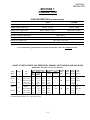
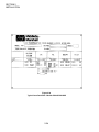
CHART OF ORIFICE SIZES, GAS PRESSURES, NOMINAL INPUT RATINGS AND GAS FLOW
IMPORTANT: This chart is not for use in Germany.
Oven
Model
Category
Gas
Type
Natural, E(H)
PS360L
&
I 2E+
PS360U
II 2H3+
PS360WB-L
II 2E+3+
PS360WB-U
II 2L3B/P
Orifice Diameter (mm)
Main
By-Pass Pilot
(Full
(Low
Flame)
Flame)
5.5
1.65
0.64
Gas Pressures (mbar) Nominally
Supply
Orifice
Input
(Inlet)
(Manifold)
(kW)
20
8
Natural, LL(L)
5.5
1.65
0.64
20
12.5
Natural,E(H)/LL(L)
4.5
1.50
0.64
20/25
*
Liquid, G30
Liquid,G31/G30
Natural, H
Natural, L
2.7
3.1
6.3
6.3
0.85
0.95
2.30
2.30
0.38
0.38
0.64
0.64
50
30/37
20
20
*
*
8.7
12
Natural,G20/G25
5.4
2.00
0.64
20/25
17/22
Liquid, G30
Liquid, G30/G31
3.1
3.5
1.40
1.40
0.38
0.38
50
30/37
*
*
*Pressure regulator (Governor) not in operation, system at inlet (supply) pressure.
The orifice pressures apply to 15°C, 1.013 mbar, dry gas.
1-1
Low
Flame
(kW)
Gas
Gas
Supply
Flow
Volume (liter/min.)
4.2 m3/h
40
50
4.4
8.8
70.0
4.9 m3/h
81.7
4.2/4.9
70.0/81.
3.1
3.1
5.3
6.1
kg/h
kg/h
m3/h
m3/h
5.3/6.1
3.9 kg/h
3.9 kg/h
88.0
102.4
88.0/102.4
---
SECTION 1
DESCRIPTION
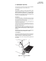
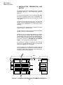
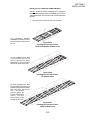
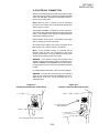
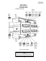
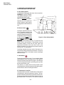
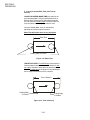
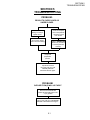
I. PRINCIPLE OF AIR FLOW
3
3
4
1
2
3
4
2
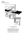
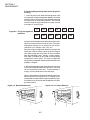
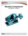
Figure 1-3 - AIR DELIVERY SYSTEM
(per oven section)
Air is heated in the heating chamber (1), then pulled into the
impellers or blowers (2), which push the air into the oven
plenum and delivers the heated air into the air fingers (3). The
fingers contain an inner plate and outer plate which columnate
the air and evenly distribute the heated air across the conveyor
belt (4) on which the product rides. The air is then pulled back
into the heating chamber (1) and the process continues.
Refer to next page for another illustration of the oven air fingers.
1-2
SECTION 1
DESCRIPTION
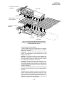
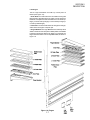
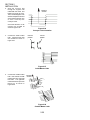
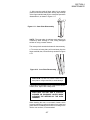
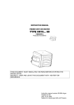
Air Flow From Plenum
Chamber
Inner Plate
Outer Plate
High Velocity Columns
of Air to Product
Air Flow From Plenum
Chamber
Inner Plate
Outer Plate
Figure 1-4. Air Fingers Showing Air Passing Through
Inner Plate And Outer Plate Which Forms High Velocity
Columns Of Air To Product.
A. Heat Transfer and How It Works
1. Heat constantly moves from a warm object to a cold object.
Heat moves using three different paths which are conduction,
radiation and convection.
Conduction: This path has to do with surface to surface
contact. The pizza dough in contact with the pan is a good
example of conduction.
Radiation: This path has to do with objects radiating heat.
Dark objects absorb heat whereas light or shiny objects reflect
more heat. Because of this, the inside of the oven is light in
color, reflecting more heat back to the product.
Convection: This path has to do with moving amounts of air.
It explains why hot air will rise and cooler air replaces hot air.
An industrial application of this principle is to incorporate a fan
to force the hot air movement which in turn will increase the heat
transfer to the product.
The oven has two large blowers to move the hot air through the
air fingers and onto the product so the most efficient bake is
achieved.
Temperature is the intensity of heat at the point which it is
sensed. As discussed above, heat flows by conduction, radiation and convection. The speed at which the heat flows is
determined by the temperature difference between the oven
and the food product. The larger the difference, the faster the
heat flows to the item that is being baked.
1-3
SECTION 1
DESCRIPTION
B. Air Fingers
The Middleby Marshall ovens are heavy duty conveyorized hot
air ovens employing vertical air streams (Figure 1-3 and 1-4) to
give uniform and intensive heating. The columnated vertical
streams of hot air provide an exceptional heat transfer rate and
generally bake faster and at lower temperatures than convection hot air or infrared heating ovens.
This is accomplished by the hot air fingers, (Figure 1-3 and 14) inside the oven. The oven can accommodate up to 6 bottom
air fingers and 6 top air fingers. Standard ovens have 5 bottom
fingers and 3 top fingers.
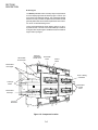
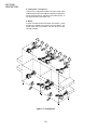
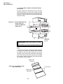
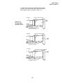
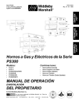
Removable
End Panels
Machinery
Compartment
Access Panel
Oven Data
Plate
Control
Panel
Removable
Jet Fingers
Front Loading
Windows
Conveyor
Motor
Removable
Crumb
Pans
Removable
Conveyor
Conveyor
Extensions
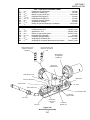
Figure 1-5. Component Location
1-4
SECTION 1
DESCRIPTION
II. COMPONENT FUNCTION
The components for the lower and upper ovens are identical.
The following description covers the lower oven.
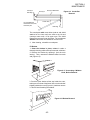
A. Conveyor
The conveyor is driven by a direct current electric motor
operating through a gear reducer, (See Figure 1-6). The motor
speed is controlled by a digital control. The stainless steel
wire belt can travel in either direction and at variable speeds.
Note that only one oven section will control the speed of the
conveyor (2 for a double tandem oven).
B. Gas Burner
Turning the heat switch to "I" will initially set up the oven purge
circuit. After approximately 45 seconds, the solid-state ignition
control lights a pilot by an electric spark.
After the pilot is lit, the main valve will open, permitting gas to go
to the burner and heat the oven.
The main burner and pilot gas are extinguished when heat is off.
This system permits the main gas valve to open only when the
pilot burner is proven to be lit.
If the pilot flame does not light or a loss of flame occurs, the main
valve closes and the red lamp is lit on the "RESET" switch. The
"RESET" switch must be pushed to restart the ignition
sequence.
Note that the gas burner of each oven section is independently
controlled by that section's temperature controller.
C. Front Window
A front window provides access to each section of the oven for
items which do not require full bake time, such as sandwiches,
cookies, small items or cheese melting processes.
The window is also used for viewing items being baked and
for cleaning.
Figure 1-6. Conveyor Drive Motor
1-5
SECTION 1
DESCRIPTION
D. Cooling Fans -- See Figure 1-7
There are two cooling fans located in the back of each oven.
These fans blow cool air in through the machinery compartment,
across the blower motors, and out the rear of the top cover, or
out the front bottom of the lower oven.
E. Blower
A blower is located in each end of each oven section. These
blowers force heated air through the oven and fingers. The
blower switch has two positions, and must be on for oven
warmup and bake.
Figure 1-7. Cooling Fans
1-6
SECTION 1
DESCRIPTION
F. Air Fingers
The Air Finger Assemblies are made up of three parts as
follows (See Figure 1-8):
1. Outer Plate-The Outer Plate is the removable covering with
tapered holes, which directs the air stream onto the product to
be baked. Outer plates are manufactured with 1 row of holes (L1
finger), 3 rows of holes (L3 finger), 6 rows of holes (L6 finger) or
no holes (a radiant finger).
2. Inner Plate -The Inner Plate directs air through the air finger,
and is vital to forming the unique air jets.
3. Finger Manifold-The Finger Manifold is the assembly which
slides on tracks into the oven plenum. Blank plates are available
to install on the plenum where an air finger is not required. The
finger manifold contains one non-adjustable baffle, as shown in
Figure 1-8.
Figure 1-8. Fingers
1-7
SECTION 1
DESCRIPTION
NOTES:
1-8
SECTION 2
INSTALLATION
SECTION 2
INSTALLATION
I. UNLOADING/UNPACKING
Your Middleby Marshall Ovens are shipped partially assembled.
Each oven section will arrive in its own crate of the following
size and weight:
Length:
Width:
Height:
Weight:
PS360U/PS360L
72 (183cm)
48 (122cm)
60 (152cm)
1675 lbs. (760kg)
PS360WB-U/PS360WB-L
66 (167cm)
57 (144cm)
50 (127cm)
1750 lbs. (780kg)
If you ordered stands for your ovens, they are shipped in
separate crates.
When your common carrier or truck line notifies you of delivery,
you must have a forklift at the facility to unload the crate(s).
If you have a door that is wider than the ovens, simply move the
ovens into your facility and set up an appointment with your
Middleby Marshall Authorized Installer.
NOTE: The width of each oven can be reduced by about 1"
(25mm) by removing the window from the oven. Window
disassembly instructions are in the Cleaning section of this
Owners Manual.
If the ovens are wider than your door opening, the oven will
have to be dismantled according to the directions in the PreInstallation Procedures Manual.
NOTE
There must be adequate clearance
between the oven and combustible construction. Clearance must also be provided for servicing and for
operation.
WARNING
Do not obstruct the flow of combustion
and ventilation air to and from your
oven. There must be no obstructions
around or underneath the oven.
WARNING
This oven must be installed in accordance
with the rules in force. Use only in a
well ventilated area. Read the
instructions before use.
2-1
SECTION 2
INSTALLATION
II. INSTALLATION, PREPARATION, AND
SUPPLY
When preparing the oven for installation at a location, the latest
International, National or Local Requirements should be
adhered to.
The ovens must be installed on an even (level) non-flammable
flooring and any adjacent walls must be non-flammable. The
minimum allowed distance from the rear of the oven to the wall
is 12 (30cm).
The ovens can be supported only by legs. No casters are
allowed. It should be made certain that there are no obstructions
located around or underneath the oven that interfere with air
circulation.
The ovens must be installed under a ventilating hood with
electrical exhaust air sensing control.
The gas supply connection should be according to applicable
ISO-228-1 or ISO-7-1 recommendations.
Normally, the oven is preparted and adjusted to the specific
gas type used by the customer. Before operating the oven,
check the label on the oven and also on the packaging that the
gas type indicated matches the local supply at the installation.
If not, refer to Section VI, PREPARATION FOR VARIOUS
GASES, in this chapter and convert as directed.
All installations, conversions and service work must be
performed by an Authorized Service Agent according to the
instructions supplied by the manufacturer.
When converting from one gas type to a different type, the
orifices supplied with the conversion kit must be checked for
proper size as specified in this manual to assure that the oven
is operating at the nominal rated input.
2"
51mm
Minimum
18"
458mm
18"
458mm
12"
305mm
Figure 2-1 - Ventilation Hood Dimensions (RECOMMENDATIONS ONLY)
2-2
3”
76mm
SECTION 2
INSTALLATION
III. VENTILATION SYSTEM
IMPORTANT
Where international, national, or local codes require
the installation of fire suppression equipment or other
supplementary equipment, DO NOT mount the
equipment directly to the oven.
MOUNTING SUCH EQUIPMENT ON THE OVEN MAY:
VOID AGENCY CERTIFICATIONS
RESTRICT SERVICE ACCESS
LEAD TO INCREASED SERVICE EXPENSES FOR
THE OWNER
REQUIREMENTS
A mechanically driven ventilation system is required for the
oven.
PROPER VENTILATION OF THE OVEN IS THE
RESPONSIBILITY OF THE OWNER.
RECOMMENDATIONS
NOTE THAT THE HOOD DIMENSIONS SHOWN IN FIGURE 2-1 (PREVIOUS PAGE) ARE RECOMMENDATIONS
ONLY. INTERNATIONAL, NATIONAL, AND LOCAL
CODES WILL VARY, AND MUST BE FOLLOWED WHEN
INSTALLING THE VENTILATION SYSTEM. ANY APPLICABLE INTERNATIONAL, NATIONAL, AND LOCAL
CODES SUPERSEDE THE RECOMMENDATIONS
SHOWN IN THIS MANUAL.
The rate of air flow exhausted through the ventilation system
may vary depending on the oven configuration and hood
design. Consult the hood manufacturer or ventilation engineer
for these specifications.
To avoid a negative pressure condition in the kitchen area,
return air must be brought back to replenish the air that was
exhausted. A negative pressure in the kitchen can cause heatrelated problems to the oven components as if there were no
ventilation at all. The best method of supplying return air is
through the heating, ventilation and air conditioning (HVAC)
system. Through the HVAC system, the air can be temperaturecontrolled for summer and winter. Return air can also be
brought in directly from outside the building, but detrimental
affects can result from extreme seasonal hot and cold
temperatures from the outdoors.
NOTE: Return air from the mechanically driven system must
not blow at opening of bake chamber. Poor oven baking
performance will result.
OTHER VENTILATION CONCERNS
Special locations, conditions, or problems may require the
services of a ventilation engineer or specialist.
Inadequate ventilation can inhibit oven performance.
It is recommended that the ventilation system and duct
work be checked at prevailing intervals as specified by the
hood manufacturer and/or HVAC engineer or specialist.
2-3
SECTION 2
INSTALLATION
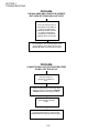
Figure 2-2 - INSTALLATION KIT
PS360L/WB-L Tandem
PS360/WB Double Tandem
PS360U/WB-U Tri Tandem
Item
Part #
Description
1
22361-0001
Flexible Gas Hose
2
4
3
PS360U/WB-U Quad Tandem
4
2
22450-0028
Adjustable Legs
8
8
12
16
3
30773
Flue Vent, 14"Lg.
2
-
-
-
4
30759
Flue Vent, 29-1/2"Lg.
-
2
3
4
5
30758
Flue Vent, 50" Lg.
-
2
-
-
6
21256-0008
Screw, 10-32 x 3/8
A/R
A/R
A/R
A/R
8
42400-0089
Master Link Kit, PS360
8
42400-0598
Master Link Kit, PS360WB
2
4
3
4
-
4
-
-
1
2
-
A/R
9
35122-0049
Attachment Strip
10
35000-1103
Stop, End Conv., PS360
10
35000-1899
Stop, End Conv., PS360WB
11
21292-0001
Scr, #2PT 10-16 x 3/4 Hx Wsh
12
33984
13
27276-0001
14
1002040
15
38615
16
27126-0238
17
31389
A/R
A/R
A/R
Thermocouple
2
4
3
4
Cable Clamp
2
4
3
4
Warranty,Parts & Serv. Dist.List
1
1
1
1
Owners Manual,English
1
1
1
1
11 Piece Hex Key Set
1
1
1
1
2
4
3
4
2
Silicone Tubing, 36 (914mm) L x
5/16 (8mm) ID x 7/16 (11mm) OD
-
35000-1454
Machinery Compartment Trim Strip
1
2
2
-
35000-1456
Front Gasket Spacer
2
4
4
4
-
35000-1457
Rear Gasket Spacer
2
4
4
4
-
37200-0013
Baking Chamber Gasket and Frame
1
2
2
2
-
37000-0696
Transition Floor Panel
-
-
-
1
-
48009-0024
Transition Top Panel
-
-
-
1
-
48009-0025
Transition Side Wall
-
-
-
2
-
35000-1748
Transition Rear Support
-
-
-
1
-
35000-1749
Transition Front Support
-
-
-
2
-
37000-0697
Transition Top Support Channel
-
-
-
2
2-4
SECTION 2
INSTALLATION
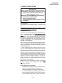
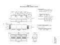
Figure 2-3
Dimensions and Data: PS360L Tandem
2”
51mm
3
45"
1143mm
40"
1016mm
42"
1067mm
32”
813mm
4
4
144-1/2"
3670mm
17-3/4"
451mm
42-3/4"
1086mm
17-3/4"
451mm
109"
2769mm
45-1/2"
1156mm
6-1/2"
165mm
31-1/2"
800mm
54-1/2"
1384mm
27-1/4"
692mm
27-1/4"
692mm
2
2
1
1
16-1/2"
11-1/2" 419mm
292mm
6”
152mm
10-1/2”
267mm
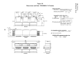
Figure 2-4
Dimensions and Data: PS360WB-L Tandem
2”
51mm
3
53"
1346mm
48"
1219mm
40”
1016mm
50"
1270mm
4
4
144-1/2"
3670mm
17-3/4"
451mm
45-1/2"
1156mm
31-1/2"
800mm
109"
2769mm
17-3/4"
451mm
50-3/4”
1289mm
6-1/2"
165mm
54-1/2"
1384mm
27-1/4"
692mm
27-1/4"
692mm
2
2
1
1
16-1/2"
11-1/2" 419mm
292mm
6”
152mm
10-1/2”
267mm
2-5
SECTION 2
INSTALLATION
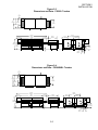
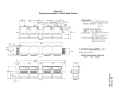
Figure 2-5
Dimensions and Data: PS360 Double Tandem
2”
51mm
3
40"
1016mm
45"
1143mm
42"
1067mm
32”
813mm
4
4
17-3/4"
451mm
109"
2769mm
34"
864mm
144-1/2"
3670mm
54-1/2"
1384mm
27-1/4"
692mm
17-3/4"
451mm
81-1/2"
2070mm
1
2
6-1/4"
158mm
27-1/4"
692mm
11-1/2"
292mm
1
2
52"
1321mm
31-1/2"
800mm
1
6-1/2"
165mm
2
2
1
1
3
11-1/2"
292mm
5-27/32"
148mm
10-1/8"
258mm
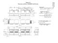
Figure 2-6
Dimensions and Data: PS360WB Double Tandem
2-6
16-1/2"
419mm
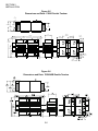
Figure 2-7
Dimensions and Data: PS360U Tri Tandem
2-7
SECTION 2
INSTALLATION
SECTION 2
INSTALLATION
Figure 2-8
Dimensions and Data: PS360WB-U Tri Tandem
2-8
Figure 2-9
Dimensions and Data: PS360U Quad Tandem
2-9
SECTION 2
INSTALLATION
SECTION 2
INSTALLATION
Figure 2-10
Dimensions and Data: PS360WB-U Quad Tandem
2-10
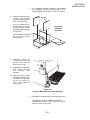
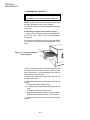
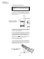
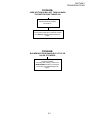
IV.
SECTION 2
INSTALLATION
THERMOCOUPLE
INSTALLATION
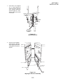
1. Install the thermocouple
sensing bulb into the correct
hole in rear of bake chamber as
shown in Figure 2-11.
2. Thread thermocouple lead
through grommet and into the
machinery compartment.
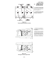
Figure 2-11
Thermocouple Installation Locations
3. Remove the right-side access panel of the machinery
compartment.
Thread the thermocouple lead
through the side of the machinery compartment as shown in
Figure 2-12, and into the electrical box (at the right-front of
the machinery compartment).
Figure 2-12
Placing the Thermocouple Leads
2-11
SECTION 2
INSTALLATION
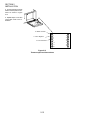
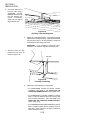
4. Connect the thermocouple
leads to the temperature controller as shown in Figure
2-13.
5. Repeat Steps 1-4 for each
of the other ovens in the installation.
8 = White = Positive
7 = Red = Negative
R = No Connection
8
9
7
10
6
11
5
12
4
13
L2
14
L1
15
16
Figure 2-13
Thermocouple Lead Connections
2-12
SECTION 2
INSTALLATION
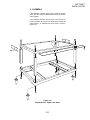
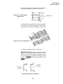
V. ASSEMBLY
If the installation includes upper ovens mounted atop lower
ovens, the ovens must be stacked before joining the tandem
ovens together.
If the installation includes ovens that are to be mounted on
stands, assemble the ovens to the stands before joining the
ovens together. An exploded view of the stand is shown in
Figure 2-14.
Figure 2-14
Exploded View - Upper Oven Stand
2-13
SECTION 2
INSTALLATION
JOINING THE OVEN BODIES
For TANDEM and DOUBLE TANDEM installations, perform
Steps 1-7 to join the ovens.
For TRI TANDEM installations, perform Steps 1-7 to join two of
the ovens together, and ensure that they are level; then, repeat
Steps 1-7 to join the third oven to the two that are assembled.
For QUAD TANDEM installations, perform Steps 1-7 for EACH
PAIR of ovens, producing two sets of two joined ovens. Do not
assemble the center bridge section at this time.
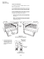
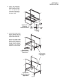
1.
Determine the proper position of the ovens by referring to
Figure 2-15. Then, move the ovens to their approximate
final locations.
NOTE: The Sealing Gasket Assembly is shown attached
to the left oven in Figure 2-15, but may be pre-mounted to
EITHER of the two ovens.
LEFT OVEN
RIGHT OVEN
Alignment
plate
Slot for
alignment
plate
Sealing gasket
assembly (premounted)
Figure 2-15
Oven Positioning and Alignment
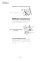
2.
Remove the rear axial cooling
fans that are adjacent to the
mating sides of the ovens, as
shown in the diagram. Leave
the fan wiring connected to
the oven.
Mating surface of
ovens (shown
from lower rear)
Wiring is still
connected
Figure 2-16
Cooling Fan Removal
2-14
SECTION 2
INSTALLATION
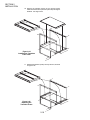
3.
Insert three of the supplied
1/2 x 5 bolts through the
holes in the frame of the right
oven, pointing outward as
shown in Figure 2-17. Then,
slide the spacers into place
on the bolts.
2-1/2 x 2-1/2
( 64 x 64mm)
spacers
Bolts
2-1/2 x 8
(64 x 203mm)
spacers
Figure 2-17
Bolts and Spacers
4.
Push the ovens together.
Check that the mounting
bolts, alignment plate, and
sealing gasket are properly
aligned.
Figure 2-18
Aligning the Ovens for Assembly
2-15
SECTION 2
INSTALLATION
5.
Check the alignment of
the track rails using a
straightedge. The rails
MUST BE LEVEL across
the gap between the
ovens. If necessary,
adjust the oven legs to
align the track rails.
Figure 2-19
Checking Track Rail Alignment
6.
Tighten all of the attaching bolts. Check that the mating
edges of the ovens align properly. If gaps appear between
the tops of the ovens, it will be necessary to loosen the
connecting bolts and realign the ovens.
IMPORTANT: If it is necessary to realign the ovens,
remember to re-check the alignment of the track rails.
7.
Attach the front trim strip
between the two ovens, as
shown in Figure 2-20.
Trim strip
Figure 2-20
Trim Strip Positioning
8.
Perform one of the following, as appropriate:
For PS360/360WB Tandem and Double Tandem
installations, skip ahead to the INSTALLING THE
CONVEYOR FRAME AND BELT section (Page 2-19).
For PS360/360WB Tri Tandem installations, perform
Steps 1-7 again to attach the third oven to the two that
have just been assembled. Then, skip ahead to the
INSTALLING THE CONVEYOR FRAME AND BELT
section (Page 2-19).
For PS360/360WB Quad Tandem installations, perform
Steps 1-7 again to attach the two remaining ovens to
each other. Then, continue on to Step 9 to attach the
center (transition) section.
2-16
SECTION 2
INSTALLATION
9.
Test-fit the transition
section of the conveyor
frame, as shown in Figure
2-21. The alignment pins
on the bottom of the frame
ensure correct spacing of
the center ovens.
Figure 2-21
Transition
Frame Placement
10. Attach the two angled support
brackets between the two
center ovens, as shown in
Figures 2-22a and 2-22b.
Note that a LOWER OVEN
(PS360L, PS360WB-L) uses
different support brackets for
the front and rear, while an
UPPER OVEN (PS360U,
PS360WB-U) uses identical
brackets on the front and rear.
Figure 2-22a
Support Brackets Lower Oven
Figure 2-22b
Support Brackets Upper Oven
Conveyor frame
shown removed
for clarity
2-17
SECTION 2
INSTALLATION
10. Remove the transition section of the conveyor frame.
Place the transition floor panel into place atop the support
brackets. See Figure 2-23.
Figure 2-23
Installing the Transition
Floor Panel
11. Replace the transition (center) conveyor section, as shown
in Figure 2-24.
Figure 2-24
Replacing the
Transition Frame
2-18
INSTALLING THE CONVEYOR FRAME AND BELT
FOR ALL TYPES OF OVENS, ENSURE THAT THE DRIVE
SECTION/END OF THE CONVEYOR FRAME IS PLACED ON
THE SAME END OF THE OVEN AS THE CONVEYOR DRIVE
MOTOR.
1.
For a TANDEM or DOUBLE
TANDEM oven, slide the conveyor
frame assembly into either end of
the oven.
Insert the conveyor frame into the oven as follows:
Figure 2-25a
Installing the Conveyor FrameTandem and Double Tandem Ovens
For TRI TANDEM ovens, slide
one center section and one end
section of the frame into EACH
END of the oven. The four sections
should butt against each other.
Figure 2-25b
Installing the Conveyor FrameTri Tandem Ovens
For QUAD TANDEM ovens, slide
two intermediate sections and one
end section of the frame into EACH
END of the oven. Butt the two
inner intermediate
sections against the
transition (center) frame
section. The other
frame sections should
butt against each other.
Figure 2-25c
Installing the Conveyor FrameQuad Tandem Ovens
2-19
SECTION 2
INSTALLATION
SECTION 2
INSTALLATION
2.
Slide the conveyor belt
through the support rods
underneath the frame, and
thread it through the oven.
Then, reach through the oven
window and pull the free end
of the belt through the oven
so that it lies atop the
conveyor frame.
Direction
of travel
Check that the links on the
conveyor are oriented as
shown in Figure 2-26.
3.
Connect the inside master
links. Check that the links
are oriented as shown in
Figure 2-27.
Figure 2-26
Conveyor Link Orientation
Incorrect
position
Correct
position
Figure 2-27
Inside Master Links
4.
Connect the outside master
links. Note that the outside
master links have right and
left sides. The right-side
master link has an open hook
facing you, as shown in
Figure 2-28.
Direction
of travel
Figure 2-28
Outside Master Links
2-20
5.
6.
Slide the top transition panel
into place. Then, slide the
two transition side panels into
place. See Figure 2-29.
7.
If the four latches are not
already attached to the side
and top transition panels,
attach them in place as shown
in Figure 2-29.
For a TANDEM, DOUBLE TANDEM, or TRI TANDEM
oven installation, skip ahead to the next section. For a
QUAD TANDEM oven installation, continue on to Step 6.
Latches
Figure 2-29
Transition
Assembly
Fasten the latches on the side
and top panels to hold the
panels in place.
Latches
8.
LOOSELY attach the
conveyor drive motor to the
end wall of the oven, as
shown in Figure 2-30.
9.
Assemble the conveyor drive
chain in place on the motor
and
conveyor
drive
sprockets.
10. Position the motor to adjust
the tension of the drive chain.
The deflection of the chain
should not exceed 1/4
(6mm). Then, tighten the
motor in place.
Figure 2-30
Conveyor Motor and Drive Chain Assembly
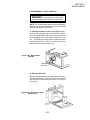
11. Assemble the end plugs and motor housing onto the oven.
TANDEM AND DOUBLE TANDEM OVENS ONLY:
Assemble the conveyor crumb trays and conveyor
extension covers onto the oven.
2-21
SECTION 2
INSTALLATION
SECTION 2
INSTALLATION
GAS OVEN ROUGH-IN
UTILITY ROUGH-IN DIMENSIONS AND POSITIONING
CAUTION
IT IS REQUIRED THAT THE OVEN BE
PLACED UNDER A VENTILATION
HOOD FOR ADEQUATE AIR SUPPLY
AND VENTILATION.
GAS SUPPLY
&
ELECTRICAL SUPPLY
5
PROVIDED BY CUSTOMER
2 To en
v
DO NOT USE CONDUIT
FOR GROUND
O
1
CIRCUIT BREAKER
1 circuit breaker/fused disconnect switch with
lockout/tagout is required for each oven
cavity. Wire each oven cavity separately.
3
5
6
ELECTRICAL SPECIFICATIONS
220-230V, 1 Ph, 8 Amp draw, 50 Hz, 2 pole, 3
wire system per oven cavity (2 hot, 1 grd).
To en
Ov
2
3
6
GAS RATING
Models PS360U/L: 135,000 BTU/HR,
34,020kcal/HR, 40kW/HR
Models PS360WB-U/-L: 170,000 BTU/HR,
42,840kcal/HR, 50kW/HR
4
To en
Ov
MINIMUM GAS METER RATING
600 Ft.3/Hour (17m3h) for 1 or 2 oven cavities.
1200 Ft.3/Hour (34m3h) for 3 or 4 oven cavities.
Minimum rating does not take other gas
appliances into consideration. Gas
consumption varies at each site. Total
BTU/HR (kcal/hr) must be calculated on high
flame off of each appliance to determine if
meter needs to be larger.
MINIMUM GAS PIPE SIZE
Natural: 2" (51mm) ID for 1 or 2 oven cavities
with runs up to 200 ft.(61m).
OR
2-1/2" (64mm) ID for 3 or 4 oven cavities with
runs up to 200 ft.(61m)
Must be a dedicated line.
Runs over 200 ft. consult factory
Propane: 1-1/2" (38mm) ID for 1 or 2 oven
cavities with runs up to 200 ft.(61m).
OR
2" (51mm) ID for 3 or 4 oven cavities with runs
up to 200 ft.(61m).
Must be a dedicated line.
Runs over 200 ft. consult factory
To en
Ov
Figure 2-31
Oven Rough-In
GAS VALVES
3/4" (19mm) ID full flow gas shut-off valve.
A separate connection and valve must be provided for each oven.
REQUIRED SUPPLY GAS PRESSURE
Natural: 20-30mbar
Propane: 50mbar
SUGGESTED
If space permits, service should be located to the left of the ovens to
allow access to switches and valves.
User Supplied Items:
ITEM
1
2
3
4
5
6
DESCRIPTION
2"(51mm) X 2"(51mm) X 3/4"(19mm) TEE
3/4"(19mm) X 3"(76mm) NIPPLE
3/4" (19mm)FULLFLOW GAS SHUT-OFF VALVE
2"(51mm) X 3/4"(19mm) 90° REDUCER ELBOW
2"(51mm) ID GAS SUPPLY PIPE LINE-NATURAL GAS
15 AMP TOGGLE SWITCH - 2 POLE for GAS
2-22
SECTION 2
INSTALLATION
VI. ELECTRICAL CONNECTION
Check the oven data plate before making any electric supply
connections. Electric supply connections must agree with data
on the oven data plate. A typical oven data plate is shown in
Figure 2-34 (on Page 2-24).
NOTE: When the oven is installed, it must be electrically
grounded in accordance with current IEC/CEE requirements
and also with local codes.
The electrical installation, including the service connection,
must comply with current IEC/CEE requirements and to local
codes. The installation must undergo a complete electrical
check before operating the oven.
Special attention must be given to the polarity of the supply
when connecting to oven input terminals.
All connections are made at one common connection at the
back of each oven. Refer to Figures 2-32 and 2-33.
NOTE: At the installation location, it is required that the
electrical supply for each oven incorporates a main circuit
breaker (not furnished). The circuit breaker must have 3mm
contact gaps breaking all poles of the supply.
WARNING: If your electrical supply has fast-acting circuit
breakers, then the initial starting current of the blower motors
in Model PS360WB-U and PS360WB-L may trip the breakers.
It is suggested to use slow-acting circuit breakers with these
models.
For further electrical information, refer to the wiring diagram.
WARNING: The connections to the exhaust system, electrical
supply, and gas supply must follow the installation instructions.
Initial start-up of the oven can be performed only by an
authorized agent.
Figure 2-32
Junction Connection Box (Lower Oven)
Figure 2-33
Junction Connection Box (Upper Oven)
3/4 (19mm) pipe for gas
oven connection
3/4 (19mm) pipe for gas oven connection
2-23
SECTION 2
INSTALLATION
Figure 2-34
Typical Oven Data Plate - Models PS360/PS360WB
2-24
VII. GAS SUPPLY FOR GAS HEATED OVENS
Pipe sizing -- Always install a shut off valve in the gas supply
line to the oven. This valve should be the same size as the
supply line.
Please remember that the longer the pipe runs, the more the
pressure drops. One 90° elbow equals a 1,2 m length of pipe.
Each oven section requires a nominal gas input as follows:
PS360U,L (per oven)
PS360WB-U, -L (per oven)
40 kW
50 kW
Follow the recommended pipe sizing and meter sizing as
indicated in the Rough-in Drawing (Figure 2-31,Page 2-22).
The flexible hose furnished with the oven must be positioned
as shown in Figure 2-35.
NOTE: The recommended pipe sizes are larger than usually
required to eliminate any operation problems. It is much less
expensive to make the initial installation large enough to do the
job rather than redoing the job later.
For lighting instructions, refer to Step-by-Step Operation in the
OPERATION Section of this manual.
CAUTION
DURING PRESSURE TESTING NOTE ONE OF THE
FOLLOWING:
1. The oven and its individual shutoff valve must be
disconnected from the gas supply piping system during
any pressure testing of that system at test pressure in
excess of 1/2 psig (3.45 kPA).
2. The oven must be isolated from the gas supply piping
system by closing its individual manual shutoff valve
during any pressure testing of the gas supply piping
system at test pressure equal to or less than 1/2 psig (3.45
kPA).
3. If the incoming pressure is over 50 mbars, a separate
regulator must be installed before the 3/4 manual gas
shutoff valve located at the rear outside of the oven.
WARNING:
To prevent damage to control
valve regulator during initial
turn on of gas, it is very
important to open manual
shutoff valve very slowly.
After the initial gas turn on, the
manual shutoff valve must
remain open except during
pressure testing as outlined in
the above steps or when
necessary during service
maintenance.
To Gas
Supply Pipe
Appliance
Connection/
Male Nipple
Full-Flow Gas
Shutoff Valve
90° ST
Elbow
Union
Flexible Hose
Correct Position
Figure 2-35
Flexible Hose Connector Installation
2-25
SECTION 2
INSTALLATION
SECTION 2
INSTALLATION
VIII. PREPARATION FOR VARIOUS GASES
Before proceeding to set up the oven for a specific gas, the
main gas supply valve and the electrical supply circuit breaker
should be turned off.
When preparing the oven for use of Group H or L Natural gases,
the orifice (Manifold) pressure should be adjusted to the values
shown in the chart on Page 1-1.
The main orifice and also the by-pass (low flame) orifice should
be changed for the specific gas type used as shown in the
following Table, also refer to Section IX, CHANGING ORIFICES.
FOR USE WITH NATURAL GAS
The input to the burner can be determined using the orifice
(manifold) pressure data or by the volume supplied using the
gas meter.
Using the orifice pressure data you must know the specific gas
quality used and when using the volume method you must
know the heat value (HuB) of the gas used (Obtainable from
your local gas supplier).
If you used the orifice pressure method, you should double
check the rated input using the volume method.
If the measured input does not correspond with the rated input,
check first that correct orifices are installed. If the orifice sizes
are as specified, check and correct the supply and orifice
pressures to obtain the correct input based on the gas meter
reading.
FOR USE WITH LIQUID (LP) GAS
When using liquid gas the converter in the multifunction gas
valve has to be turned end over end - 180° (Refer to Figure 236). This takes the governor out of operation.
2-26
SECTION 2
INSTALLATION
GAS TYPE AND PRESSURE LABEL
IT ......
GB ....
FR ....
DE ....
DE ....
ES ....
NL .....
BE ....
II2H3+ ................... Predisposto per gas metano .................................................... 20 mbar
II2H3+ ................... Adjusted for natural gas ........................................................... 20 mbar
II2E+3+ ................. Essaye au gaz naturel (E/L) ................................................ 20-25 mbar
II2ELL3B/P ........... Eingestellt auf Erdgas (E) ........................................................ 20 mbar
II2ELL3B/P ........... Eingestellt auf Erdgas (LL) ....................................................... 20 mbar
II2H3+ ................... Preparado para gas natural ...................................................... 20 mbar
II2L3B/P ................ Aangelegd op aardgas ............................................................. 25 mbar
I2E+ ....................... Essaye au gaz naturel/aangelo op aardgas ........................ 20-25 mbar
IT ......
GB ....
FR ....
DE ....
ES ....
NL .....
BE ....
II2H3+ ................... Predisposto per G.P.L. ................................................... 28-30/37 mbar
II2H3+ ................... Adjusted for L.P.G. ......................................................... 28-30/37 mbar
II2E+3+ ................. Essaye au gaz naturel liquide ........................................ 28-30/37 mbar
II2ELL3B/P ........... Eingestellt auf Flüssiggas ........................................................ 50 mbar
II2H3+ ................... Preparado para gas liquido ............................................ 28-30/37 mbar
II2L3B/P ................ Aangelegd op vloeibaar gas ..................................................... 30 mbar
I3+ ......................... Aangelegd op vloeibaar gas/essaye au gaz liquide ....... 28-30/37 mbar
GAS TYPE AND PRESSURE LABEL
Insert Converter In this
Position for use with LP
Gas
Insert Converter In this
Position for Pressure
Regulation
Burner Blower
Air Adjustment
PlateBurner
High Flame
Solenoid Valve
Outlet Pressure Tap
Main Orifice
Governor Adjustment
Gas Converter
1/2 Nuts
Inlet Pressure Tap
1/2 Compression Nut
Low Flame
Bypass Orifice
3/4 Union
Pilot Line
Combination
Gas Control
Valve
Figure 2-36
Burner/Piping Assembly
2-27
Low Flame
Bypass Line
SECTION 2
INSTALLATION
IX. CHANGING ORIFICES
TO CHANGE MAIN ORIFICE (Refer to Figure 2-36)
1. Turn off main gas supply valve.
2. Open 3/4" union in gas supply line.
3. Remove 1/2" nuts securing gas train to the burner housing.
4. Using a 11/16" wrench remove orifice from the mounting
flange.
5. Install new orifice in reverse order.
WARNING
Before operating oven check for gas leaks!
TO CHANGE BYPASS (LOW FLAME) ORIFICE (Refer to
Figure 2-36)
1. Turn off main gas supply valve.
2. Open 3/4" union in gas supply line.
3. With 1/2" wrench loosen compression nuts securing bypass
tube to solenoid valve.
4. Remove orifice from bypass tube.
5. Install new orifice in reverse order.
X. VOLUMETRIC METHOD
WARNING
Before operating oven check for gas leaks!
IMPORTANT
During these measurements, no other gas appliance should be
in operation being supplied from the same gas meter.
To determine gas flow setting value E:
E
NB
HuB
= Liters/min.
= Rated input in kW
= Heat (Calorific) value of gas in kW/m 3
E
= NB
HuB
To determine the time of 0.1m3 (100 liters) gas usage:
Time in minutes =100
E
The time of the gas flow through the meter should be taken
with a stopwatch.
1. Remove cover screw from the gas valve pressure (governor)
adjustment valve.
2. Open main gas supply valve and start oven according to
supplied instructions with the temperature control at
maximum setting.
3. Once oven is in operation, adjust pressure valve (governor)
to the calculated volume using the time for 100 liters of flow
through. Turning the adjustment screw clockwise will
increase the flow and counter-clockwise will reduce it.
2-28
4. Replace cover screw on adjustment valve and turn off main
gas supply valve.
5. Record the reading obtained from the gas meter and
calculate obtained gas flow. Compare this to the indicated
flow in the CHART OF ORIFICE SIZES, GAS PRESSURES,
NOMINAL INPUT RATINGS AND GAS FLOW on Page 1.
6. Note the following comments and procedures to assure
correct gas supply pressure and adjusting the gas valve to
obtain proper orifice (manifold) pressure.
XI.
VARIATIONS OF RATED SUPPLY
PRESSURES
Special attention should be given to the supply pressure and
gas flow pressure at the supply connection to the oven. The
nominal supply pressure for gas family Group 2 (natural gas)
should be 20 mbar.
If the supply pressure is lower or higher than the rated (nominal)
pressure then the reason should be investigated and the gas
supplier contacted.
If the supply pressure is lower than 17 mbars or higher than 25
mbars then the oven should be shut down and the gas supplier
notified. No adjustment of the oven controls should be made
and the oven should not be operated.
TO CHECK GAS SUPPLY PRESSURE:
1. Close main gas supply valve.
2. Remove supply (inlet) pressure measuring stud screw from
gas valve and attach the manometer to the stud.
3. Open main gas supply valve and restart oven with
temperature control at maximum setting.
4. Measure inlet (supply) pressure. For all natural gases this
should be between 17 and 25 mbars.
5. Turn oven off, close main gas supply valve, remove
manometer from stud and tighten cover screw in to pressure
measuring stud.
ORIFICE (MANIFOLD) PRESSURE METHOD:
1. Turn off main gas supply valve.
2. Remove pressure measuring stud screw located at the
out-flow (closest to gas burner) of the gas valve and attach
a manometer.
3. Remove cover screw from the gas valve pressure (governor)
adjustment valve.
4. Open main gas supply valve and start oven according to
supplied instructions with the temperature control at
maximum setting.
5. Once oven is in operation, adjust pressure valve (governor)
to the orifice pressure value as shown for the specific gas
in the Gas Specifications Table.
6. Turn oven off, close main gas supply valve, remove U tube
manometer and tighten cover screw into pressure measuring
stud.
2-29
SECTION 2
INSTALLATION
SECTION 2
INSTALLATION
SPECIAL NOTICES:
The ovens should be operated only in an area that has good air
circulation.
The oven must be installed under an electrically powered
ventilating hood.
Installation of replacement parts requiring access to the interior
of the oven is permitted only by authorized service personnel.
The operator should be properly trained to the functioning of
the oven.
This instructions manual should be supplied to the operator.
Constructional changes to the area where the oven is installed
shall not affect the air supply to the oven.
The installation, start-up and changes required when changing
from one gas type to another can be performed only by a
certified professional.
These ovens are intended only for commercial use and are to
be operated only by professionals.
It is required that the oven is regularly inspected for proper
functioning. The frequency of inspections are dependent on
the oven usage, however it should be performed at least once
a year.
After adjustments or service work the oven has to be checked
for gas leaks.
NOTE: After conversions, readjustments or service work the
oven has to be tested for proper functioning. Basically the
following applies:
Testing for gas leaks,
Testing for correct air supply, specifically to the burner
blower,
Testing of proper combustion and gas supply,
Testing of correct gas supply controls,
Testing the flue gas escape from the oven,
Testing the vent system of the installation location.
2-30
SECTION 3
OPERATION
SECTION 3
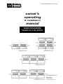
OPERATION
I. CONTROL FUNCTIONS
Blower
Switch
Ignition
Reset
Switch
Heat
Switch
Conveyor
Speed
Controller
and
Conveyor Temperature
Indicator Switch
Controller
Door
Safety
Switch
(Inside)
RESET
RESET
Ignition
Reset
Switch
Door
Safety
Switch
(Inside)
Blower
Switch
Heat
Switch
Conveyor Temperature
Switch
Controller
Figure 3-1. Oven Controls
NOTE
The ovens are only for professional use, and the
ovens may only be used by qualified personnel.
3-1
Conveyor
Speed
Controller
and
Indicator
SECTION 3
OPERATION
II. COMPONENT INFORMATION AND
LOCATION (EACH OVEN SECTION)
A. Door Safety Switch
Located at the inside upper left corner of the control box.
WARNING: DO NOT TOUCH
THE WIRES GOING TO THIS
SWITCH BECAUSE CURRENT IS ALWAYS PRESENT.
Opening the control panel permits the switch to open, disconnecting power to all electrical controls.
B. Blower Switch
The blower switch has two positions. The switch must be in the
"I" (on) position for the burner to
ignite, permitting the oven to heat.
The blowers circulate air throughout the oven and must stay on
Figure 3-2. Door Safety Switch
during baking and during the cooldown cycle (above 93°C [200°F])
to prevent blower bearing damage. To protect the two
blower motors and bearings, a thermostatic override
(cool-down switch) is built into the oven. When the
temperature inside the oven is over 180° F (82° C), the
blowers continue to run even after the blower switch is
turned to the "0" (off) position.
Centrifugal switches (built into each of the blower motors) serve as safety interlocks for the burner. The burner
cannot ignite if either of the blower motors' centrifugal
switches is open.
C. Heat Switch
Turning the heat switch to the "I" (on) position initially
starts operation of the oven purge circuit. After approximately 45 seconds, the pilot burner lights. After the pilot
is lit, the main gas valve opens, permitting gas to go to the
burner and heat the oven.
This switch is in series with the burner blower motor
centrifugal switch, the high-temperature limit safety switch,
and the blower motors' centrifugal switches.
D. Temperature Controller
The temperature controller is a solid-state, on/off type for
maintaining the desired temperature setting. The temperature controller continuously monitors the ovens' temperature and actuates the high-flame solenoid valve in
gas heated ovens. The heat is 'on' for the time required
3-2
SECTION 3
OPERATION
to maintain a constant temperature.
The temperature controller contains a high-limit (safety)
switch that shuts down the oven when the oven reaches
343°C (650° F) and a low-limit switch which allows the
oven to cool down to 82° C (180° F) before shutting off the
blowers.
E. Conveyor Switch
The on/off ("I"/"0") switch for the conveyor drive motor is
on the control panel of the controlling oven section. Also
on this control panel is the conveyor speed control and
indicator (Figures 3-3A and 3-3B).
1
1
Minutes
:
1
(Display shows
dc voltage value
corresponding
to the conveyor
motor speed)
0
Seconds
Figure 3-3A. Conveyor Speed Control and
Indicator - Tandem and Double Tandem
Oven
Figure 3-3B. Conveyor Speed Control and
Indicator - Tri Tandem and Quad Tandem
Oven
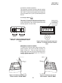
MEASURING CONVEYOR SPEED.
To measure the conveyor speed, place an item at the
product entrance end of the oven bake chamber, as
shown in Figure 3-4. Time how long it takes for the
leading edge of the item to go from the entrance end of
the bake chamber to its exit end (Figure 3-5). This is your
conveyor speed or bake time.
Figure 3-4. Product at entrance end
of bake chamber - BEGIN TIMING
Figure 3-5. Product at exit end of
bake chamber - END OF TIMING
3-3
SECTION 3
OPERATION
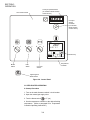
Conveyor Speed Indicator
(Tri Tandem / Quad Tandem
version shown)
Oven Control Panel
Conveyor
Speed
Controller
(Tri Tandem /
Quad Tandem
version shown)
Middleby Marshall
ALM
HEAT
0
I
0
I
0
I
260
1
C
SET PT
Service Key
Heat
Switch
Blower
Switch
RESET
Temperature
Controller
Conveyor
Switch
Lighted Ignition
Reset Switch
Figure 3-6. Control Panel
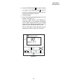
III. STEP-BY-STEP OPERATION
A. Startup Procedure
1. Turn on the main disconnect switch / circuit breaker.
2. Open the manual gas supply valve.
3. Turn the blower switch
to "I" (on)
4. Set the temperature controller to the desired baking
temperature. (Refer to paragraph B for Temperature
Controller Operating Instructions.)
3-4
SECTION 3
OPERATION
5. Turn the heat switch
to "I" (on). The ignition
system goes through a 45-second purge time after which
the pilot lights and ignites the burner. If the burner does
not ignite, the red light on the "RESET" pushbutton switch
will light. The RESET switch must be pushed to restart
the ignition sequence. This restarting can be repeated;
however, after 15 minutes, the control system goes into
automatic 'lockout.' When 'lockout' occurs, the heat
switch must be turned to "0" (off) before the restart
procedure can be repeated to ignite the burner.
6. Set the conveyor speed controller
to the desired
value.
7. Turn the conveyor switch
to "I" (on).
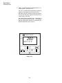
B. Temperature Controller Operation Instructions
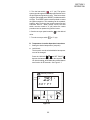
1. Setting the desired temperature ('set point').
a. Lock/Unlock
The 'set point' must be unlocked before its temperature can be changed.
Press the UNLOCK
and SET POINT
buttons simultaneously to unlock the set point. The
UP Arrow button ▲ and DOWN Arrow button ▼ will
now function for 60 seconds. See Figure 3-7.
Middleby Marshall
ALM
HEAT
1 2
1
251
SET PT
Figure 3-7
3-5
C
SECTION 3
OPERATION
b. Changing the 'set point'.
Press the UP Arrow button ▲ or DOWN Arrow button
▼. The temperature set point will increase or decrease. If this button is kept depressed, the temperature set point will continue to increase or decrease at
a faster rate.
2. Displaying the actual oven temperature. See Figure
3-8.
a. To check the oven temperature, press the TEMPERATURE button once to display the actual oven
temperature. The word “TEMP” also appears.
Middleby Marshall
ALM
HEAT
251
TEMP
Figure 3-8
3-6
C
SECTION 3
OPERATION
b. Press the TEMPERATURE
button again to display
the 'set point'. If the TEMPERATURE
button is not
pressed, the display automatically shows the temperature set point after 60 seconds.
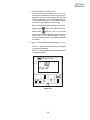
3. Display Messages
a. ALM - The ALM window will display either a “2” or will
be blank. See Figure 3-9.
AA. The “2” signals that the oven temperature is
below 200°F (93°C). The “2” appears only while the
oven is initially heating and has not yet reached
200°F (93°C), or after the heat switch is turned off
and the oven has cooled below 200°F (93°C).
BB. The ALM window is blank whenever the oven
temperature is 200°F to 650°F (93°C to 343°C).
Middleby Marshall
ALM
HEAT
2
92
SET PT
Figure 3-9
3-7
C
SECTION 3
OPERATION
b. HEAT - The HEAT window will display either a "1" or
it will be blank. See Figure 3-10.
AA. The "1" signals that the temperature controller is
calling for heat and the burner is turned full on.
BB. When the HEAT window is blank, the temperature set point has been reached and the burner is
turned down to low flame.
CC. During normal operation, the "1" continues to
blink on and off every few seconds. This indicates
that the temperature controller is maintaining the
desired temperature (the 'set point').
Middleby Marshall
ALM
HEAT
1
260
SET PT
Figure 3-10
3-8
C
SECTION 3
OPERATION
c. FAILSF (Failsafe) See Figure 3-11.
AA. If the oven does not reach 200°F (93°C) in 15
minutes, the temperature controller will shut off the
high flame valve and begin flashing “FAILSF” and
“SET PT” alternately. You will also note that the “2”
in the ALM window stays on. This condition signals
a problem in oven heating or heat sensing.
BB. To reset the temperature controller, turn off the
blower switch
. Wait 10 seconds and turn the
blower switch
back on. The “2” in the ALM
window, the current temperature set point, and the
words “SET PT” will be displayed again. The temperature controller will now cycle through its normal
procedures.
d. F/C - The F/C window will display either an “F” or a
“C”.
AA. The “F” indicates that the temperature displayed
is in degrees Fahrenheit.
BB. The “C” indicates that the temperature displayed
is in degrees Celsius.
Middleby Marshall
ALM
HEAT
2
92
FAIL SF
Figure 3-11
3-9
C
SECTION 3
OPERATION
C. Shutdown Procedure
1. Turn the blower
and heat
switches to "0" (off).
NOTE: The blowers will remain on, until the oven
temperature cools down to 93°C (200°F) at which time
they will stop automatically.
2. Turn the conveyor switch
to "0" (off), after making
certain that there are no products left on the conveyor
inside the oven.
3. Turn off the main gas supply valve.
4. Open the window.
Power Failure
In case of power failure, turn off all switches, open the
oven window on each oven section, and remove all
products from the conveyor. After power has been restored, perform the normal startup procedure.
D. Products Baked/Cooked in Ovens
The oven can be used to bake and/or cook a wide variety
of food products, such as pizza, pizza-type products,
cookies, sandwiches, and others.
3-10
SECTION 3
OPERATION
E. Bake Time vs. Bake Temperature
Along with oven temperature, the bake is dependent on
the conveyor speed (or 'bake time'); that is, the time it
takes the product to pass through the oven.
1. 'Bake time' is actually conveyor speed and is defined
as the time the pizza is actually in the oven. This is
measured by noting the time when the leading edge of
the pizza enters the oven and the time the leading edge
of the pizza leaves the oven. This is adjusted by using the
conveyor speed controller.
2. 'Bake temperature' is adjusted by changing the set
point of the temperature controller to the desired temperature. (Instructions for changing the set point of the
temperature controller appear earlier in this Section of
the manual.
3. When establishing a bake time and temperature for a
given product, a general rule can be: As the bake time
increases, the bake temperature decreases. The reverse is also true; increase the temperature, decrease
the time. Yet, there are limits to this rule because a
golden- brown appearance is desired. Going to extremes
will result in a burnt exterior and raw interior, or it will result
in a very light-colored, but over-baked, product.
After a good bake has been established, the fine adjustments should be made by holding either the bake time or
bake temperature constant.
Example: Thick pizza has good brown color on top and
bottom, but the center is not quite done. Bake time: 8
minutes, 0 seconds. Bake temperature: 248°C (480°F).
Solution: Hold the temperature constant, but increase
the bake time to 8 minutes, 30 seconds. This will give the
heat more time to penetrate to the center of the product.
3-11
SECTION 3
OPERATION
F. Conveyor Speed (Bake Time) and Time of
Delivery
CONVEYOR SPEED (BAKE TIME)- As stated in the
previous paragraphs, conveyor speed (bake time) is
defined as the amount of time that elapses between
the time when the Leading edge of a pizza enters the
oven and when the leading edge exits the oven.
Conveyor Speed (Bake Time) is controlled by
adjusting the conveyor speed controller.
Bake Time will be the same for any size pizza
Bake Time
Leading Edge of Product
Figure 3-12. Bake Time
TIME OF DELIVERY- Time Of Delivery is the amount of
time that elapses between the moment when the Leading edge of a product enters the oven and the moment
when the Trailing edge of the product is fully discharged
and is ready to be delivered to the customer.
Time of Delivery
Leading Edge
of Product
Trailing Edge
of Product
Figure 3-13. Time of Delivery
3-12
SECTION 4
MAINTENANCE
SECTION 4
MAINTENANCE
CAUTION: DO NOT use any abrasive cleaning materials or water spray. Wipe clean only.
Cleaning with a water hose or pressurized steam
cleaning equipment voids the oven warranty.
I. MAINTENANCE - DAILY
A. Exterior
Everyday, clean the outside of the oven using a soft cloth
moistened with mild detergent. Rinse by wiping with a
soft cloth moistened with clear water. Wipe dry.
B. Fans and Grills
1. Clean the two fan grills (Figure 4-1) on the rear of each
oven DAILY. Also, clean the grills for cooling air exhaust:
one located on top of an upper oven, and one located
beneath the front of a lower oven. Clean these grills with
a stiff, nylon-type brush.
2. Check the air intake of the cooling fans DAILY. The
best time to check is right after starting the oven. IF THE
FAN(S) ARE NOT OPERATING CORRECTLY, THEY
MUST BE REPAIRED OR REPLACED IMMEDIATELY.
Serious damage could be done to the blower motors and/
or the solid-state electrical components. When a fan fails,
the end panel must be removed as a temporary solution.
CAUTION: This is only a temporary solution. Oven
damage may still occur while a fan remains unrepaired.
3. Clean the ventilating hood air filters.
Top Grill
Upper Cooling Fans
Lower Cooling Fans
Lower Grill
(beneath oven front)
Figure 4-1. Oven Cooling Fans -Two on upper oven and two on lower oven
4-1
SECTION 4
MAINTENANCE
C. Conveyor Belts (Tandem and Double Tandem
Ovens only)
Everyday, stand at the unloading end of the conveyor
with a brush (Figure 4-2, lower oven). Brush all crumbs
off the belt so that they fall into the crumb pan below the
conveyor. (Figure 4-3 shows crumb pans for both upper
and lower ovens.)
Figure 4-2. Conveyor Belt Cleaning
(lower oven) and
Crumb Pan Removal
(upper oven)
Lower Oven
Cooling Air
Exhaust
WARNING: Before performing any further
maintenance, turn the main power switch off.
D. Crumb Pans (Tandem and Double Tandem Ovens
only)
1. Remove and clean the crumb pans at both ends of an
oven (Figure 4-2, upper oven). Remove each crumb pan
by lifting the end of the pan nearest the end of the
conveyor; then, slide the pan toward the oven slightly.
Now, lower the front of the pan, and pull it from beneath
the conveyor. (Figure 4-4 shows a view of this procedure
from the side of the conveyor.)
Upper Oven,
Left End
Figure 4-3. Crumb Pans, Upper
and Lower Ovens
Lower Oven
Upper Oven,
Right End
4-2
SECTION 4
MAINTENANCE
Conveyor
End Stop
Lift, and slide pan
toward the oven; then,
lower the pan.
Conveyor
Conveyor Extension
Figure 4-4. Crumb Pan
Removal
Crumb Pan
End Plug
The crumb pans with cutout holes (and an end shield
attached on the inner end) are used at the left end
(conveyor motor end) of an upper oven. The shield
protects the conveyor motor from heat. The crumb pans
without cutout holes are installed on a lower oven.
2. After cleaning, reinstall the crumb pans.
E. Window
1. Clean the window in place, unless it needs a
thorough cleaning, which will require removal, as follows.
2. Remove the window by opening it (into the oven
interior). Then, unscrew the window knobs from each
end (Figure 4-5).
Figure 4-5. Unscrewing a Window
Knob, Before Removal
3. Push the open window all the way inside the oven,
making sure it is clear of the frame. Now, turn the window
sideways inside the oven (Figure 4-6,) and then remove
it. This will avoid breaking the window.
Figure 4-6. Window Removal
4-3
SECTION 4
MAINTENANCE
II. MAINTENANCE - MONTHLY
WARNING: Before performing any further
maintenance, turn the main power switch off.
NOTE: The interior may require cleaning more than once
a month, depending on the volume of baking.
To clean the interior, you must disassemble some parts
of the oven.
A. Removing conveyor from oven for cleaning
1. Remove the crumb pans (Tandem and Double Tandem Ovens only). Refer to the Daily Maintenance
procedures.
2. Remove conveyor extension covers from both ends of
oven (Figure 4-7) (Tandem and Double Tandem Ovens
only).
Figure 4-7. Conveyor Extension
Cover Removal
3. After removing the bottom shield (located below the
shroud) by removing its three screws, remove the conveyor motor shroud. Loosen the hanger screw; then, lift
and remove the motor shroud.
4. Remove the end plugs from the oven side with the
conveyor drive motor.
5. Release the tension from the conveyor drive chain, as
follows:
• Tandem and Double Tandem Oven:
Lift, and push, the conveyor assembly slightly into the
oven.
• Tri Tandem and Quad Tandem Oven:
Loosen the mounting bolts of the conveyor drive motor.
Shift the motor to release the drive chain tension.
6. Detach the drive chain from the conveyor drive shaft
sprocket.
4-4
SECTION 4
MAINTENANCE
NOTE: The conveyor assembly of a tandem or a double
tandem oven can be removed from either end of oven. If
you are removing the conveyor from the end of the
oven without the drive motor, the drive sprocket assembly must be removed by loosening the 3/32" set
screw on the conveyor drive shaft collar. Then, remove
the drive sprocket assembly from the end of the shaft.
7. Pull the conveyor belt until its master links are near the
end of the upper belt surface. Disconnect the master
links. (Refer to the later procedure "E. Conveyor belt link
removal", in this section, for additional details.)
8. Remove the conveyor belt by rolling it into a bundle.
Place the belt in a safe location.
9. Slide the conveyor frame sections out of the oven,
placing them on the floor for cleaning.
NOTE: Tandem and Double Tandem Ovens - Conveyor
frame sections are connected to each
other with hinges. The conveyor frame
must be removed as a unit.
Tri Tandem and Quad Tandem Ovens - Conveyor
frame sections are separate and must be
removed from both ends of the oven.
10. For a Quad Tandem oven, remove the two transition
side panels. Then, slide out the top transition panel to
obtain acces to the conveyor frame sections for removal.
(Refer to pages 2-19 through 2-21 for illustrations of
these oven components and text that clarifies the procedure.)
4-5
SECTION 4
MAINTENANCE
B. Disassembling the blank plates and air fingers for
cleaning
1. Use a felt pen to mark each plate and all parts of the
air fingers with a 'finger arrangement' identifier, like those
shown in Figure 4-8, when removing the blank plates and
air fingers from the oven baking chamber. This marking
should include the finger manifold, inner plate, and the
outer plate of each air finger.
T1
T2
T3
T4
T5
T6
B1
B2
B3
B4
B5
B6
Figure 4-8. "Finger Arrangement"
Identifiers
Air fingers and blank plates should be marked in the order
shown, as viewed from the front of the oven. (The finger
arrangement numbers for an upper oven can be preceded with a "U"; example: UB1, UT2, etc.)
Record the finger arrangement identifiers on paper and
identify the number of rows of holes in each air finger's
outer plate, along with the position of each 'full-blank'
plate and 'half-blank' plate. Usually, a finger arrangement label is installed on the inside of the machinery
compartment access panel. The finger arrangement
should still be recorded for instances when the label is not
available or illegible.
2. Slide each blank plate and air finger along the channels
on the rear baking chamber wall (Figure 4-9), until each
can be extracted from the oven. Prevent twisting or
turning, to avoid interference in the channel(s).
Remove top and bottom air fingers and blank plates from
either end of the oven (Figure 4-10). It is highly recommended that each plate and air finger be marked (Figure
4-8) at the time of removal to aide reinstallation in exactly
the same position.
Figure 4-9. Blank Plate Removal
Figure 4-10. Air Finger Removal
4-6
SECTION 4
MAINTENANCE
3. After removing each air finger, place it in an upright
position to remove the outer plate . Gently, step on the lip
of the finger manifold and pull the outer plate upward to
disassemble it, as shown in Figure 4-11.
Figure 4-11. Outer Plate Disassembly
NOTE: The outer plate is stainless steel and may be
cleaned by either soaking in a hot, strong detergent
solution or using a caustic cleaner.
The conveyor belt can also be cleaned in the same way.
4. To remove an inner plate, pull its end away from the
finger manifold, then, lift it out and up, as shown in Figure
4-12.
Figure 4-12. Inner Plate Disassembly
CAUTION: DO NOT use caustic cleaner on an
inner plate or a finger manifold, to avoid damage.
5. While the oven chamber is clear, clean it with a vacuum
cleaner; then, wipe it with a damp cloth.
CAUTION: DO NOT USE A CAUSTIC
CLEANER OR EXCESSIVE WATER WHEN
CLEANING THE INTERIOR OF THE OVEN
CHAMBER.
When cleaning the oven, a non-caustic cleaner, which
removes baked-on grease and carbon from metal and
glass and will not damage the aluminum coating on the
interior oven surface, is recommended.
4-7
SECTION 4
MAINTENANCE
C. Reassembly and reinstallation of air fingers
Each air finger is made up of one inner plate, one outer
plate and one finger manifold (Figure 4-13). Be sure to
match the 'finger arrangement' identifier markings
(T1, T2, etc.) on all the parts of each air finger during
reassembly.
Figure 4-13. Air Finger
Parts
1. Reassemble the inner plate into the finger manifold
(Figure 4-14). Keep your fingers clear to avoid pinching
them.
The inner plate of an air finger will only go in one way
because of its design, as shown in Figure 4-15.
Figure 4-14. Inner
Plate Reassembly
Details
2. Reassemble the outer plate by sliding it downward in
the grooves on the side walls of the finger manifold. Keep
your fingers clear to avoid pinching them.
3. Reinstall the air fingers (and blank plates) into the oven
by sliding them into the channels on the rear oven wall,
using the method shown in Figures 4-9 and 4-10. Support the outer end of the finger (oven front), while pushing
the base of the finger manifold portion along the channels. Remember to reinstall each air finger, according to
the identifiers marked on them. Each finger must go back
into its original location.
Each oven is shipped with a finger arrangement label
mounted inside the machinery compartment access panel.
If this sticker is not legible, it is very important to mark the
fingers as they were pulled out and to record them on a
separate paper.
4-8
SECTION 4
MAINTENANCE
4. Ensure that the air fingers and blank plates fit tightly
together in the channel with edges interlocked and no
space between edges, as shown in Figure 4-15.
Top Finger
Incorrect, Too Much Space
Blank
Plate
Figure 4-15.
Air Finger Reinstallation Details
Tab on Outer Plate of Finger
(Located in Channel)
Incorrect, Too Much Space
Top Finger
Blank
Plate
Tab on Outer Plate of Finger
(Located in Channel)
Top Finger
Correct-Edges Overlap Completely
Blank
Plate
Tab on Outer Plate of Finger
(Located in Channel)
4-9
SECTION 4
MAINTENANCE
D. Checking conveyor belt tension
WARNING: Oven conveyor belt must be cool for
adjusting tension. DO NOT adjust belt when
HOT.
1. Check the belt tension by lifting the conveyor belt
(Figure 4-16). (The conveyor assembly can either be in
or out of the oven.) The belt should not lift more than 3"
to 4" (75 to 100 mm).
Figure 4-16. Checking
Conveyor Belt Tension
2. Adjust the conveyor belt tension screws (located on
the right end of the conveyor assembly) for the proper 3"
to 4" (75 to 100 mm) deflection.
3. If the conveyor belt tension screws do not allow the
conveyor belt to have the proper tension, at least one
entire link must be removed. Use the following procedure
("E. Conveyor belt link removal") to remove a link.
When conveyor belt is under proper tension, proceed
directly to "F. Conveyor reassembly into oven".
E. Conveyor belt link removal
1. Remove an entire conveyor belt link by positioning the
belt's master links near the end of the conveyor belt , as
shown in Figure 4-17. (The conveyor assembly can
either be in or out of the oven.)
Figure 4-17. Conveyor Belt
Master Links
Master Links
4-10
SECTION 4
MAINTENANCE
2. Unhook the master links at the end of conveyor belt,
using long-nosed pliers, as shown in Figure 4-18.
Figure 4-18. Unhooking the
Master Links
Master Link
3. Unhook the complete belt link to be removed and slide
it out (Figure 4-19). (Do not discard this removed link
because it can be used for making spare master links.)
Figure 4-19. Entire Link Removal
4. Prepare to reconnect the inner master links.
IMPORTANT NOTICE: Before connecting the inner
master links, notice that these links have a correct
position. The master link (at the right in Figure 4-20) is in
the correct (horns up) position for inserting into the
conveyor belt. The link with horns facing down is in the
incorrect position.
Correct
Position
Incorrect
Position
Figure 4-20. Master Link Positions
4-11
SECTION 4
MAINTENANCE
5. Reconnect the outer master links, as shown in Figure
4-21.
Figure 4-21. Outer Master Link
Connection
IMPORTANT NOTICE: The outer master links have right
and left sides to them. The right-edge master link has an
open hook facing you, as shown in Figure 4-22. This will
match the right outer edge of the conveyor belt. Remember, this hook travels backwards on the conveyor.
Direction of Travel
Figure 4-22. Right-edge Outer Master
Link Position
F. Conveyor reinstallation into an oven
Refer to the procedures "INSTALLING THE CONVEYOR
FRAME AND BELT" in Section 2, pages 2-19 through 221, for details concerning conveyor reinstallation and
reassembly.
4-12
SECTION 4
MAINTENANCE
II. MAINTENANCE - EVERY 3 MONTHS
WARNING:
All electric power must be shut
off before beginning this maintenance procedure.
NOTE: It is recommended that an authorized Middleby
Marshall service agent should perform the 3-month and
6-month maintenance procedures.
A. Cleaning the blower motors (See Figure 4-23.)
Remove the end panels from the machinery compartment. Clean the blower motors in each oven section and
the surrounding area, using either compressed air or
CO2. Thoroughly blow out the motor compartment and
vents inside the motor. Failure to do this may cause
premature failure of the electric motor.
Figure 4-23. Blower Motor
Cleaning
Blow out
this area
B. Electrical terminals
Open the control panel door by loosening the two screws.
Tighten all electrical control terminal screws, including
the electrical contactor terminal screws, as shown in
Figure 4-24.
Figure 4-24. Electrical Terminal
Maintenance
4-13
SECTION 4
MAINTENANCE
IV. MAINTENANCE - EVERY 6 MONTHS
WARNING:
All electric power must be shut
off before beginning this maintenance procedure.
NOTE: It is recommended that an authorized Middleby
Marshall service agent should perform the 3-month and
6-month maintenance procedures.
A. Check the brushes of the conveyor drive motor; when
worn to less than 3/32" (2.4mm), replace the brushes.
B. Clean and inspect the burner nozzle and electrode
assembly. Also, check the oven venting system; clean
the oven flue, when necessary.
C. For Tandem and Double Tandem Ovens, check the
conveyor drive shaft bushings and spacers. Replace any
worn parts.
D. For Tri Tandem and Quad Tandem Ovens, check
for wear on the conveyor shaft bearings. If necessary,
lubricate with NLGI #2 Lithium-base Grease.
IMPORTANT NOTICES:
• The installation, startup, and changes required for
changing from one gas type to another can be
performed only by an authorized service agent.
• Installation of replacement parts requiring access
to the interior of the oven is permitted only by
authorized service personnel.
• If there are any problems with the operation of the
oven, an authorized service agent must be called.
• Obtaining a service contract with a manufacturer's
authorized service agent is recommended.
4-14
SECTION 5
TROUBLESHOOTING
SECTION 5
TROUBLESHOOTING
PROBLEM:
PRODUCTS OVERCOOKED OR
UNDERCOOKED
Check for correct
setting of conveyor
speed control.
Check set temperature on temperature
controller of each
oven section.
Set conveyor speed
control at correct setting.
Refer to OPERATION
Section for procedure
to set temperatures
correctly.
Verify food
preparation
process.
If products still cook
incorrectly call your local
Middleby Marshall
Authorized Service Agent.
PROBLEM:
OVEN SECTION(S) WILL NOT HEAT
Check to see if both blower
switch and heat switch are in the
"I" (on) position
If still no heat, call your local Middleby
Marshall Authorized Service Agent.
5-1
SECTION 5
TROUBLESHOOTING
PROBLEM:
OVEN BLOWER AND CONVEYOR OPERATE
BUT OVEN SECTION(S) WILL NOT HEAT
If the oven section(s) do not
reach 200°F (93°C) within 15
minutes, the temperature
controller(s) will flash "FAILSF".
To reset the temperature
controller(s), turn the blower
switch(es) off for 30 seconds.
Try restarting the oven section(s) again. If the
oven section(s) will not heat, call your local
Middleby Marshall Authorized Service Agent.
PROBLEM:
CONVEYOR WILL NOT HOLD PROPER SPEED
OR WILL NOT RUN AT ALL
Check if conveyor is
jammed on something in
oven.
Check for proper tension of conveyor drive
chain and conveyor belt. Refer to MAINTENANCE Section for checking procedure.
Check that drive sprocket
is tight.
If conveyor still will not run, call your local
Middleby Marshall Authorized Service Agent.
5-2
SECTION 5
TROUBLESHOOTING
PROBLEM:
OVEN SECTION(S) WILL NOT TURN ON WHEN
THE SWITCHES ARE TURNED ON
Check if wall circuit breakers
are turned on.
If oven section(s) still will not respond, call your
local Middleby Marshall Authorized Service
Agent.
PROBLEM:
BLOWER MOTORS RUNNING BUT LITTLE OR
NO AIR AT FINGERS
Fingers assembled
incorrectly after cleaning. Refer to the
MAINTENANCE section for instructions
on removing and reassembling the air
fingers.
5-3
SECTION 5
TROUBLESHOOTING
NOTES:
5-4
SECTION 6
ELECTRICAL SCHEMATICS
SECTION 7
ELECTRICAL SCHEMATICS
6-1
SECTION 6
ELECTRICAL SCHEMATICS
6-2
Electrical Wiring Diagram:
PS360/360WB Tandem and Double Tandem Ovens
6-3
SECTION 6
ELECTRICAL SCHEMATICS
Electrical Wiring Diagram:
PS360/360WB Tri Tandem and Quad Tandem Ovens
SECTION 6
ELECTRICAL SCHEMATICS
6-4
Electrical Schematic:
PS360/360WB Tandem Ovens (all versions)
NOTES:
6-5
SECTION 6
ELECTRICAL SCHEMATICS
A MIDDLEBY COMPANY
Middleby Cooking Systems Group 1400 Toastmaster Drive Elgin, IL 60120 (847)741-3300 FAX (847)741-4406
Middleby Corp 24-Hour Service Hotline 1-800-238-8444
www.middleby.com