1
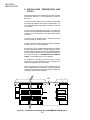
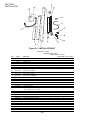
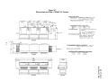
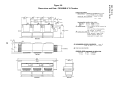
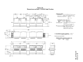
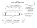
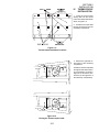
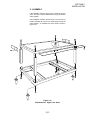
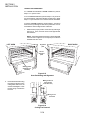
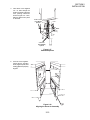
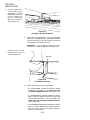
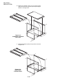
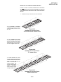
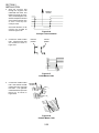
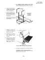
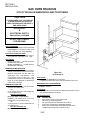
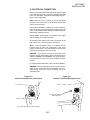
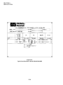
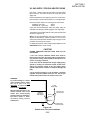
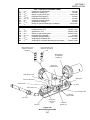
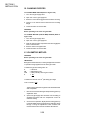
SECTION 2 INSTALLATION SECTION 2 INSTALLATION I. UNLOADING/UNPACKING Your Middleby Marshall Ovens are shipped partially assembled. Each oven section will arrive in its own crate of the following size and weight: Length: Width: Height: Weight: PS360U/PS360L 72 (183cm) 48 (122cm) 60 (152cm) 1675 lbs. (760kg) PS360WB-U/PS360WB-L 66 (167cm) 57 (144cm) 50 (127cm) 1750 lbs. (780kg) If you ordered stands for your ovens, they are shipped in separate crates. When your common carrier or truck line notifies you of delivery, you must have a forklift at the facility to unload the crate(s). If you have a door that is wider than the ovens, simply move the ovens into your facility and set up an appointment with your Middleby Marshall Authorized Installer. NOTE: The width of each oven can be reduced by about 1" (25mm) by removing the window from the oven. Window disassembly instructions are in the Cleaning section of this Owners Manual. If the ovens are wider than your door opening, the oven will have to be dismantled according to the directions in the PreInstallation Procedures Manual. NOTE There must be adequate clearance between the oven and combustible construction. Clearance must also be provided for servicing and for operation. WARNING Do not obstruct the flow of combustion and ventilation air to and from your oven. There must be no obstructions around or underneath the oven. WARNING This oven must be installed in accordance with the rules in force. Use only in a well ventilated area. Read the instructions before use. 2-1 SECTION 2 INSTALLATION II. INSTALLATION, PREPARATION, AND SUPPLY When preparing the oven for installation at a location, the latest International, National or Local Requirements should be adhered to. The ovens must be installed on an even (level) non-flammable flooring and any adjacent walls must be non-flammable. The minimum allowed distance from the rear of the oven to the wall is 12 (30cm). The ovens can be supported only by legs. No casters are allowed. It should be made certain that there are no obstructions located around or underneath the oven that interfere with air circulation. The ovens must be installed under a ventilating hood with electrical exhaust air sensing control. The gas supply connection should be according to applicable ISO-228-1 or ISO-7-1 recommendations. Normally, the oven is preparted and adjusted to the specific gas type used by the customer. Before operating the oven, check the label on the oven and also on the packaging that the gas type indicated matches the local supply at the installation. If not, refer to Section VI, PREPARATION FOR VARIOUS GASES, in this chapter and convert as directed. All installations, conversions and service work must be performed by an Authorized Service Agent according to the instructions supplied by the manufacturer. When converting from one gas type to a different type, the orifices supplied with the conversion kit must be checked for proper size as specified in this manual to assure that the oven is operating at the nominal rated input. 2" 51mm Minimum 18" 458mm 18" 458mm 12" 305mm Figure 2-1 - Ventilation Hood Dimensions (RECOMMENDATIONS ONLY) 2-2 3” 76mm SECTION 2 INSTALLATION III. VENTILATION SYSTEM IMPORTANT Where international, national, or local codes require the installation of fire suppression equipment or other supplementary equipment, DO NOT mount the equipment directly to the oven. MOUNTING SUCH EQUIPMENT ON THE OVEN MAY: VOID AGENCY CERTIFICATIONS RESTRICT SERVICE ACCESS LEAD TO INCREASED SERVICE EXPENSES FOR THE OWNER REQUIREMENTS A mechanically driven ventilation system is required for the oven. PROPER VENTILATION OF THE OVEN IS THE RESPONSIBILITY OF THE OWNER. RECOMMENDATIONS NOTE THAT THE HOOD DIMENSIONS SHOWN IN FIGURE 2-1 (PREVIOUS PAGE) ARE RECOMMENDATIONS ONLY. INTERNATIONAL, NATIONAL, AND LOCAL CODES WILL VARY, AND MUST BE FOLLOWED WHEN INSTALLING THE VENTILATION SYSTEM. ANY APPLICABLE INTERNATIONAL, NATIONAL, AND LOCAL CODES SUPERSEDE THE RECOMMENDATIONS SHOWN IN THIS MANUAL. The rate of air flow exhausted through the ventilation system may vary depending on the oven configuration and hood design. Consult the hood manufacturer or ventilation engineer for these specifications. To avoid a negative pressure condition in the kitchen area, return air must be brought back to replenish the air that was exhausted. A negative pressure in the kitchen can cause heatrelated problems to the oven components as if there were no ventilation at all. The best method of supplying return air is through the heating, ventilation and air conditioning (HVAC) system. Through the HVAC system, the air can be temperaturecontrolled for summer and winter. Return air can also be brought in directly from outside the building, but detrimental affects can result from extreme seasonal hot and cold temperatures from the outdoors. NOTE: Return air from the mechanically driven system must not blow at opening of bake chamber. Poor oven baking performance will result. OTHER VENTILATION CONCERNS Special locations, conditions, or problems may require the services of a ventilation engineer or specialist. Inadequate ventilation can inhibit oven performance. It is recommended that the ventilation system and duct work be checked at prevailing intervals as specified by the hood manufacturer and/or HVAC engineer or specialist. 2-3 SECTION 2 INSTALLATION Figure 2-2 - INSTALLATION KIT PS360L/WB-L Tandem PS360/WB Double Tandem PS360U/WB-U Tri Tandem Item Part # Description 1 22361-0001 Flexible Gas Hose 2 4 3 PS360U/WB-U Quad Tandem 4 2 22450-0028 Adjustable Legs 8 8 12 16 3 30773 Flue Vent, 14"Lg. 2 - - - 4 30759 Flue Vent, 29-1/2"Lg. - 2 3 4 5 30758 Flue Vent, 50" Lg. - 2 - - 6 21256-0008 Screw, 10-32 x 3/8 A/R A/R A/R A/R 8 42400-0089 Master Link Kit, PS360 8 42400-0598 Master Link Kit, PS360WB 2 4 3 4 - 4 - - 1 2 - A/R 9 35122-0049 Attachment Strip 10 35000-1103 Stop, End Conv., PS360 10 35000-1899 Stop, End Conv., PS360WB 11 21292-0001 Scr, #2PT 10-16 x 3/4 Hx Wsh 12 33984 13 27276-0001 14 1002040 15 38615 16 27126-0238 17 31389 A/R A/R A/R Thermocouple 2 4 3 4 Cable Clamp 2 4 3 4 Warranty,Parts & Serv. Dist.List 1 1 1 1 Owners Manual,English 1 1 1 1 11 Piece Hex Key Set 1 1 1 1 2 4 3 4 2 Silicone Tubing, 36 (914mm) L x 5/16 (8mm) ID x 7/16 (11mm) OD - 35000-1454 Machinery Compartment Trim Strip 1 2 2 - 35000-1456 Front Gasket Spacer 2 4 4 4 - 35000-1457 Rear Gasket Spacer 2 4 4 4 - 37200-0013 Baking Chamber Gasket and Frame 1 2 2 2 - 37000-0696 Transition Floor Panel - - - 1 - 48009-0024 Transition Top Panel - - - 1 - 48009-0025 Transition Side Wall - - - 2 - 35000-1748 Transition Rear Support - - - 1 - 35000-1749 Transition Front Support - - - 2 - 37000-0697 Transition Top Support Channel - - - 2 2-4 SECTION 2 INSTALLATION Figure 2-3 Dimensions and Data: PS360L Tandem 2” 51mm 3 45" 1143mm 40" 1016mm 42" 1067mm 32” 813mm 4 4 144-1/2" 3670mm 17-3/4" 451mm 42-3/4" 1086mm 17-3/4" 451mm 109" 2769mm 45-1/2" 1156mm 6-1/2" 165mm 31-1/2" 800mm 54-1/2" 1384mm 27-1/4" 692mm 27-1/4" 692mm 2 2 1 1 16-1/2" 11-1/2" 419mm 292mm 6” 152mm 10-1/2” 267mm Figure 2-4 Dimensions and Data: PS360WB-L Tandem 2” 51mm 3 53" 1346mm 48" 1219mm 40” 1016mm 50" 1270mm 4 4 144-1/2" 3670mm 17-3/4" 451mm 45-1/2" 1156mm 31-1/2" 800mm 109" 2769mm 17-3/4" 451mm 50-3/4” 1289mm 6-1/2" 165mm 54-1/2" 1384mm 27-1/4" 692mm 27-1/4" 692mm 2 2 1 1 16-1/2" 11-1/2" 419mm 292mm 6” 152mm 10-1/2” 267mm 2-5 SECTION 2 INSTALLATION Figure 2-5 Dimensions and Data: PS360 Double Tandem 2” 51mm 3 40" 1016mm 45" 1143mm 42" 1067mm 32” 813mm 4 4 17-3/4" 451mm 109" 2769mm 34" 864mm 144-1/2" 3670mm 54-1/2" 1384mm 27-1/4" 692mm 17-3/4" 451mm 81-1/2" 2070mm 1 2 6-1/4" 158mm 27-1/4" 692mm 11-1/2" 292mm 1 2 52" 1321mm 31-1/2" 800mm 1 6-1/2" 165mm 2 2 1 1 3 11-1/2" 292mm 5-27/32" 148mm 10-1/8" 258mm Figure 2-6 Dimensions and Data: PS360WB Double Tandem 2-6 16-1/2" 419mm Figure 2-7 Dimensions and Data: PS360U Tri Tandem 2-7 SECTION 2 INSTALLATION SECTION 2 INSTALLATION Figure 2-8 Dimensions and Data: PS360WB-U Tri Tandem 2-8 Figure 2-9 Dimensions and Data: PS360U Quad Tandem 2-9 SECTION 2 INSTALLATION SECTION 2 INSTALLATION Figure 2-10 Dimensions and Data: PS360WB-U Quad Tandem 2-10 IV. SECTION 2 INSTALLATION THERMOCOUPLE INSTALLATION 1. Install the thermocouple sensing bulb into the correct hole in rear of bake chamber as shown in Figure 2-11. 2. Thread thermocouple lead through grommet and into the machinery compartment. Figure 2-11 Thermocouple Installation Locations 3. Remove the right-side access panel of the machinery compartment. Thread the thermocouple lead through the side of the machinery compartment as shown in Figure 2-12, and into the electrical box (at the right-front of the machinery compartment). Figure 2-12 Placing the Thermocouple Leads 2-11 SECTION 2 INSTALLATION 4. Connect the thermocouple leads to the temperature controller as shown in Figure 2-13. 5. Repeat Steps 1-4 for each of the other ovens in the installation. 8 = White = Positive 7 = Red = Negative R = No Connection 8 9 7 10 6 11 5 12 4 13 L2 14 L1 15 16 Figure 2-13 Thermocouple Lead Connections 2-12 SECTION 2 INSTALLATION V. ASSEMBLY If the installation includes upper ovens mounted atop lower ovens, the ovens must be stacked before joining the tandem ovens together. If the installation includes ovens that are to be mounted on stands, assemble the ovens to the stands before joining the ovens together. An exploded view of the stand is shown in Figure 2-14. Figure 2-14 Exploded View - Upper Oven Stand 2-13 SECTION 2 INSTALLATION JOINING THE OVEN BODIES For TANDEM and DOUBLE TANDEM installations, perform Steps 1-7 to join the ovens. For TRI TANDEM installations, perform Steps 1-7 to join two of the ovens together, and ensure that they are level; then, repeat Steps 1-7 to join the third oven to the two that are assembled. For QUAD TANDEM installations, perform Steps 1-7 for EACH PAIR of ovens, producing two sets of two joined ovens. Do not assemble the center bridge section at this time. 1. Determine the proper position of the ovens by referring to Figure 2-15. Then, move the ovens to their approximate final locations. NOTE: The Sealing Gasket Assembly is shown attached to the left oven in Figure 2-15, but may be pre-mounted to EITHER of the two ovens. LEFT OVEN RIGHT OVEN Alignment plate Slot for alignment plate Sealing gasket assembly (premounted) Figure 2-15 Oven Positioning and Alignment 2. Remove the rear axial cooling fans that are adjacent to the mating sides of the ovens, as shown in the diagram. Leave the fan wiring connected to the oven. Mating surface of ovens (shown from lower rear) Wiring is still connected Figure 2-16 Cooling Fan Removal 2-14 SECTION 2 INSTALLATION 3. Insert three of the supplied 1/2 x 5 bolts through the holes in the frame of the right oven, pointing outward as shown in Figure 2-17. Then, slide the spacers into place on the bolts. 2-1/2 x 2-1/2 ( 64 x 64mm) spacers Bolts 2-1/2 x 8 (64 x 203mm) spacers Figure 2-17 Bolts and Spacers 4. Push the ovens together. Check that the mounting bolts, alignment plate, and sealing gasket are properly aligned. Figure 2-18 Aligning the Ovens for Assembly 2-15 SECTION 2 INSTALLATION 5. Check the alignment of the track rails using a straightedge. The rails MUST BE LEVEL across the gap between the ovens. If necessary, adjust the oven legs to align the track rails. Figure 2-19 Checking Track Rail Alignment 6. Tighten all of the attaching bolts. Check that the mating edges of the ovens align properly. If gaps appear between the tops of the ovens, it will be necessary to loosen the connecting bolts and realign the ovens. IMPORTANT: If it is necessary to realign the ovens, remember to re-check the alignment of the track rails. 7. Attach the front trim strip between the two ovens, as shown in Figure 2-20. Trim strip Figure 2-20 Trim Strip Positioning 8. Perform one of the following, as appropriate: For PS360/360WB Tandem and Double Tandem installations, skip ahead to the INSTALLING THE CONVEYOR FRAME AND BELT section (Page 2-19). For PS360/360WB Tri Tandem installations, perform Steps 1-7 again to attach the third oven to the two that have just been assembled. Then, skip ahead to the INSTALLING THE CONVEYOR FRAME AND BELT section (Page 2-19). For PS360/360WB Quad Tandem installations, perform Steps 1-7 again to attach the two remaining ovens to each other. Then, continue on to Step 9 to attach the center (transition) section. 2-16 SECTION 2 INSTALLATION 9. Test-fit the transition section of the conveyor frame, as shown in Figure 2-21. The alignment pins on the bottom of the frame ensure correct spacing of the center ovens. Figure 2-21 Transition Frame Placement 10. Attach the two angled support brackets between the two center ovens, as shown in Figures 2-22a and 2-22b. Note that a LOWER OVEN (PS360L, PS360WB-L) uses different support brackets for the front and rear, while an UPPER OVEN (PS360U, PS360WB-U) uses identical brackets on the front and rear. Figure 2-22a Support Brackets Lower Oven Figure 2-22b Support Brackets Upper Oven Conveyor frame shown removed for clarity 2-17 SECTION 2 INSTALLATION 10. Remove the transition section of the conveyor frame. Place the transition floor panel into place atop the support brackets. See Figure 2-23. Figure 2-23 Installing the Transition Floor Panel 11. Replace the transition (center) conveyor section, as shown in Figure 2-24. Figure 2-24 Replacing the Transition Frame 2-18 INSTALLING THE CONVEYOR FRAME AND BELT FOR ALL TYPES OF OVENS, ENSURE THAT THE DRIVE SECTION/END OF THE CONVEYOR FRAME IS PLACED ON THE SAME END OF THE OVEN AS THE CONVEYOR DRIVE MOTOR. 1. For a TANDEM or DOUBLE TANDEM oven, slide the conveyor frame assembly into either end of the oven. Insert the conveyor frame into the oven as follows: Figure 2-25a Installing the Conveyor FrameTandem and Double Tandem Ovens For TRI TANDEM ovens, slide one center section and one end section of the frame into EACH END of the oven. The four sections should butt against each other. Figure 2-25b Installing the Conveyor FrameTri Tandem Ovens For QUAD TANDEM ovens, slide two intermediate sections and one end section of the frame into EACH END of the oven. Butt the two inner intermediate sections against the transition (center) frame section. The other frame sections should butt against each other. Figure 2-25c Installing the Conveyor FrameQuad Tandem Ovens 2-19 SECTION 2 INSTALLATION SECTION 2 INSTALLATION 2. Slide the conveyor belt through the support rods underneath the frame, and thread it through the oven. Then, reach through the oven window and pull the free end of the belt through the oven so that it lies atop the conveyor frame. Direction of travel Check that the links on the conveyor are oriented as shown in Figure 2-26. 3. Connect the inside master links. Check that the links are oriented as shown in Figure 2-27. Figure 2-26 Conveyor Link Orientation Incorrect position Correct position Figure 2-27 Inside Master Links 4. Connect the outside master links. Note that the outside master links have right and left sides. The right-side master link has an open hook facing you, as shown in Figure 2-28. Direction of travel Figure 2-28 Outside Master Links 2-20 5. 6. Slide the top transition panel into place. Then, slide the two transition side panels into place. See Figure 2-29. 7. If the four latches are not already attached to the side and top transition panels, attach them in place as shown in Figure 2-29. For a TANDEM, DOUBLE TANDEM, or TRI TANDEM oven installation, skip ahead to the next section. For a QUAD TANDEM oven installation, continue on to Step 6. Latches Figure 2-29 Transition Assembly Fasten the latches on the side and top panels to hold the panels in place. Latches 8. LOOSELY attach the conveyor drive motor to the end wall of the oven, as shown in Figure 2-30. 9. Assemble the conveyor drive chain in place on the motor and conveyor drive sprockets. 10. Position the motor to adjust the tension of the drive chain. The deflection of the chain should not exceed 1/4 (6mm). Then, tighten the motor in place. Figure 2-30 Conveyor Motor and Drive Chain Assembly 11. Assemble the end plugs and motor housing onto the oven. TANDEM AND DOUBLE TANDEM OVENS ONLY: Assemble the conveyor crumb trays and conveyor extension covers onto the oven. 2-21 SECTION 2 INSTALLATION SECTION 2 INSTALLATION GAS OVEN ROUGH-IN UTILITY ROUGH-IN DIMENSIONS AND POSITIONING CAUTION IT IS REQUIRED THAT THE OVEN BE PLACED UNDER A VENTILATION HOOD FOR ADEQUATE AIR SUPPLY AND VENTILATION. GAS SUPPLY & ELECTRICAL SUPPLY 5 PROVIDED BY CUSTOMER 2 To en v DO NOT USE CONDUIT FOR GROUND O 1 CIRCUIT BREAKER 1 circuit breaker/fused disconnect switch with lockout/tagout is required for each oven cavity. Wire each oven cavity separately. 3 5 6 ELECTRICAL SPECIFICATIONS 220-230V, 1 Ph, 8 Amp draw, 50 Hz, 2 pole, 3 wire system per oven cavity (2 hot, 1 grd). To en Ov 2 3 6 GAS RATING Models PS360U/L: 135,000 BTU/HR, 34,020kcal/HR, 40kW/HR Models PS360WB-U/-L: 170,000 BTU/HR, 42,840kcal/HR, 50kW/HR 4 To en Ov MINIMUM GAS METER RATING 600 Ft.3/Hour (17m3h) for 1 or 2 oven cavities. 1200 Ft.3/Hour (34m3h) for 3 or 4 oven cavities. Minimum rating does not take other gas appliances into consideration. Gas consumption varies at each site. Total BTU/HR (kcal/hr) must be calculated on high flame off of each appliance to determine if meter needs to be larger. MINIMUM GAS PIPE SIZE Natural: 2" (51mm) ID for 1 or 2 oven cavities with runs up to 200 ft.(61m). OR 2-1/2" (64mm) ID for 3 or 4 oven cavities with runs up to 200 ft.(61m) Must be a dedicated line. Runs over 200 ft. consult factory Propane: 1-1/2" (38mm) ID for 1 or 2 oven cavities with runs up to 200 ft.(61m). OR 2" (51mm) ID for 3 or 4 oven cavities with runs up to 200 ft.(61m). Must be a dedicated line. Runs over 200 ft. consult factory To en Ov Figure 2-31 Oven Rough-In GAS VALVES 3/4" (19mm) ID full flow gas shut-off valve. A separate connection and valve must be provided for each oven. REQUIRED SUPPLY GAS PRESSURE Natural: 20-30mbar Propane: 50mbar SUGGESTED If space permits, service should be located to the left of the ovens to allow access to switches and valves. User Supplied Items: ITEM 1 2 3 4 5 6 DESCRIPTION 2"(51mm) X 2"(51mm) X 3/4"(19mm) TEE 3/4"(19mm) X 3"(76mm) NIPPLE 3/4" (19mm)FULLFLOW GAS SHUT-OFF VALVE 2"(51mm) X 3/4"(19mm) 90° REDUCER ELBOW 2"(51mm) ID GAS SUPPLY PIPE LINE-NATURAL GAS 15 AMP TOGGLE SWITCH - 2 POLE for GAS 2-22 SECTION 2 INSTALLATION VI. ELECTRICAL CONNECTION Check the oven data plate before making any electric supply connections. Electric supply connections must agree with data on the oven data plate. A typical oven data plate is shown in Figure 2-34 (on Page 2-24). NOTE: When the oven is installed, it must be electrically grounded in accordance with current IEC/CEE requirements and also with local codes. The electrical installation, including the service connection, must comply with current IEC/CEE requirements and to local codes. The installation must undergo a complete electrical check before operating the oven. Special attention must be given to the polarity of the supply when connecting to oven input terminals. All connections are made at one common connection at the back of each oven. Refer to Figures 2-32 and 2-33. NOTE: At the installation location, it is required that the electrical supply for each oven incorporates a main circuit breaker (not furnished). The circuit breaker must have 3mm contact gaps breaking all poles of the supply. WARNING: If your electrical supply has fast-acting circuit breakers, then the initial starting current of the blower motors in Model PS360WB-U and PS360WB-L may trip the breakers. It is suggested to use slow-acting circuit breakers with these models. For further electrical information, refer to the wiring diagram. WARNING: The connections to the exhaust system, electrical supply, and gas supply must follow the installation instructions. Initial start-up of the oven can be performed only by an authorized agent. Figure 2-32 Junction Connection Box (Lower Oven) Figure 2-33 Junction Connection Box (Upper Oven) 3/4 (19mm) pipe for gas oven connection 3/4 (19mm) pipe for gas oven connection 2-23 SECTION 2 INSTALLATION Figure 2-34 Typical Oven Data Plate - Models PS360/PS360WB 2-24 VII. GAS SUPPLY FOR GAS HEATED OVENS Pipe sizing -- Always install a shut off valve in the gas supply line to the oven. This valve should be the same size as the supply line. Please remember that the longer the pipe runs, the more the pressure drops. One 90° elbow equals a 1,2 m length of pipe. Each oven section requires a nominal gas input as follows: PS360U,L (per oven) PS360WB-U, -L (per oven) 40 kW 50 kW Follow the recommended pipe sizing and meter sizing as indicated in the Rough-in Drawing (Figure 2-31,Page 2-22). The flexible hose furnished with the oven must be positioned as shown in Figure 2-35. NOTE: The recommended pipe sizes are larger than usually required to eliminate any operation problems. It is much less expensive to make the initial installation large enough to do the job rather than redoing the job later. For lighting instructions, refer to Step-by-Step Operation in the OPERATION Section of this manual. CAUTION DURING PRESSURE TESTING NOTE ONE OF THE FOLLOWING: 1. The oven and its individual shutoff valve must be disconnected from the gas supply piping system during any pressure testing of that system at test pressure in excess of 1/2 psig (3.45 kPA). 2. The oven must be isolated from the gas supply piping system by closing its individual manual shutoff valve during any pressure testing of the gas supply piping system at test pressure equal to or less than 1/2 psig (3.45 kPA). 3. If the incoming pressure is over 50 mbars, a separate regulator must be installed before the 3/4 manual gas shutoff valve located at the rear outside of the oven. WARNING: To prevent damage to control valve regulator during initial turn on of gas, it is very important to open manual shutoff valve very slowly. After the initial gas turn on, the manual shutoff valve must remain open except during pressure testing as outlined in the above steps or when necessary during service maintenance. To Gas Supply Pipe Appliance Connection/ Male Nipple Full-Flow Gas Shutoff Valve 90° ST Elbow Union Flexible Hose Correct Position Figure 2-35 Flexible Hose Connector Installation 2-25 SECTION 2 INSTALLATION SECTION 2 INSTALLATION VIII. PREPARATION FOR VARIOUS GASES Before proceeding to set up the oven for a specific gas, the main gas supply valve and the electrical supply circuit breaker should be turned off. When preparing the oven for use of Group H or L Natural gases, the orifice (Manifold) pressure should be adjusted to the values shown in the chart on Page 1-1. The main orifice and also the by-pass (low flame) orifice should be changed for the specific gas type used as shown in the following Table, also refer to Section IX, CHANGING ORIFICES. FOR USE WITH NATURAL GAS The input to the burner can be determined using the orifice (manifold) pressure data or by the volume supplied using the gas meter. Using the orifice pressure data you must know the specific gas quality used and when using the volume method you must know the heat value (HuB) of the gas used (Obtainable from your local gas supplier). If you used the orifice pressure method, you should double check the rated input using the volume method. If the measured input does not correspond with the rated input, check first that correct orifices are installed. If the orifice sizes are as specified, check and correct the supply and orifice pressures to obtain the correct input based on the gas meter reading. FOR USE WITH LIQUID (LP) GAS When using liquid gas the converter in the multifunction gas valve has to be turned end over end - 180° (Refer to Figure 236). This takes the governor out of operation. 2-26 SECTION 2 INSTALLATION GAS TYPE AND PRESSURE LABEL IT ...... GB .... FR .... DE .... DE .... ES .... NL ..... BE .... II2H3+ ................... Predisposto per gas metano .................................................... 20 mbar II2H3+ ................... Adjusted for natural gas ........................................................... 20 mbar II2E+3+ ................. Essaye au gaz naturel (E/L) ................................................ 20-25 mbar II2ELL3B/P ........... Eingestellt auf Erdgas (E) ........................................................ 20 mbar II2ELL3B/P ........... Eingestellt auf Erdgas (LL) ....................................................... 20 mbar II2H3+ ................... Preparado para gas natural ...................................................... 20 mbar II2L3B/P ................ Aangelegd op aardgas ............................................................. 25 mbar I2E+ ....................... Essaye au gaz naturel/aangelo op aardgas ........................ 20-25 mbar IT ...... GB .... FR .... DE .... ES .... NL ..... BE .... II2H3+ ................... Predisposto per G.P.L. ................................................... 28-30/37 mbar II2H3+ ................... Adjusted for L.P.G. ......................................................... 28-30/37 mbar II2E+3+ ................. Essaye au gaz naturel liquide ........................................ 28-30/37 mbar II2ELL3B/P ........... Eingestellt auf Flüssiggas ........................................................ 50 mbar II2H3+ ................... Preparado para gas liquido ............................................ 28-30/37 mbar II2L3B/P ................ Aangelegd op vloeibaar gas ..................................................... 30 mbar I3+ ......................... Aangelegd op vloeibaar gas/essaye au gaz liquide ....... 28-30/37 mbar GAS TYPE AND PRESSURE LABEL Insert Converter In this Position for use with LP Gas Insert Converter In this Position for Pressure Regulation Burner Blower Air Adjustment PlateBurner High Flame Solenoid Valve Outlet Pressure Tap Main Orifice Governor Adjustment Gas Converter 1/2 Nuts Inlet Pressure Tap 1/2 Compression Nut Low Flame Bypass Orifice 3/4 Union Pilot Line Combination Gas Control Valve Figure 2-36 Burner/Piping Assembly 2-27 Low Flame Bypass Line SECTION 2 INSTALLATION IX. CHANGING ORIFICES TO CHANGE MAIN ORIFICE (Refer to Figure 2-36) 1. Turn off main gas supply valve. 2. Open 3/4" union in gas supply line. 3. Remove 1/2" nuts securing gas train to the burner housing. 4. Using a 11/16" wrench remove orifice from the mounting flange. 5. Install new orifice in reverse order. WARNING Before operating oven check for gas leaks! TO CHANGE BYPASS (LOW FLAME) ORIFICE (Refer to Figure 2-36) 1. Turn off main gas supply valve. 2. Open 3/4" union in gas supply line. 3. With 1/2" wrench loosen compression nuts securing bypass tube to solenoid valve. 4. Remove orifice from bypass tube. 5. Install new orifice in reverse order. X. VOLUMETRIC METHOD WARNING Before operating oven check for gas leaks! IMPORTANT During these measurements, no other gas appliance should be in operation being supplied from the same gas meter. To determine gas flow setting value E: E NB HuB = Liters/min. = Rated input in kW = Heat (Calorific) value of gas in kW/m 3 E = NB HuB To determine the time of 0.1m3 (100 liters) gas usage: Time in minutes =100 E The time of the gas flow through the meter should be taken with a stopwatch. 1. Remove cover screw from the gas valve pressure (governor) adjustment valve. 2. Open main gas supply valve and start oven according to supplied instructions with the temperature control at maximum setting. 3. Once oven is in operation, adjust pressure valve (governor) to the calculated volume using the time for 100 liters of flow through. Turning the adjustment screw clockwise will increase the flow and counter-clockwise will reduce it. 2-28 4. Replace cover screw on adjustment valve and turn off main gas supply valve. 5. Record the reading obtained from the gas meter and calculate obtained gas flow. Compare this to the indicated flow in the CHART OF ORIFICE SIZES, GAS PRESSURES, NOMINAL INPUT RATINGS AND GAS FLOW on Page 1. 6. Note the following comments and procedures to assure correct gas supply pressure and adjusting the gas valve to obtain proper orifice (manifold) pressure. XI. VARIATIONS OF RATED SUPPLY PRESSURES Special attention should be given to the supply pressure and gas flow pressure at the supply connection to the oven. The nominal supply pressure for gas family Group 2 (natural gas) should be 20 mbar. If the supply pressure is lower or higher than the rated (nominal) pressure then the reason should be investigated and the gas supplier contacted. If the supply pressure is lower than 17 mbars or higher than 25 mbars then the oven should be shut down and the gas supplier notified. No adjustment of the oven controls should be made and the oven should not be operated. TO CHECK GAS SUPPLY PRESSURE: 1. Close main gas supply valve. 2. Remove supply (inlet) pressure measuring stud screw from gas valve and attach the manometer to the stud. 3. Open main gas supply valve and restart oven with temperature control at maximum setting. 4. Measure inlet (supply) pressure. For all natural gases this should be between 17 and 25 mbars. 5. Turn oven off, close main gas supply valve, remove manometer from stud and tighten cover screw in to pressure measuring stud. ORIFICE (MANIFOLD) PRESSURE METHOD: 1. Turn off main gas supply valve. 2. Remove pressure measuring stud screw located at the out-flow (closest to gas burner) of the gas valve and attach a manometer. 3. Remove cover screw from the gas valve pressure (governor) adjustment valve. 4. Open main gas supply valve and start oven according to supplied instructions with the temperature control at maximum setting. 5. Once oven is in operation, adjust pressure valve (governor) to the orifice pressure value as shown for the specific gas in the Gas Specifications Table. 6. Turn oven off, close main gas supply valve, remove U tube manometer and tighten cover screw into pressure measuring stud. 2-29 SECTION 2 INSTALLATION SECTION 2 INSTALLATION SPECIAL NOTICES: The ovens should be operated only in an area that has good air circulation. The oven must be installed under an electrically powered ventilating hood. Installation of replacement parts requiring access to the interior of the oven is permitted only by authorized service personnel. The operator should be properly trained to the functioning of the oven. This instructions manual should be supplied to the operator. Constructional changes to the area where the oven is installed shall not affect the air supply to the oven. The installation, start-up and changes required when changing from one gas type to another can be performed only by a certified professional. These ovens are intended only for commercial use and are to be operated only by professionals. It is required that the oven is regularly inspected for proper functioning. The frequency of inspections are dependent on the oven usage, however it should be performed at least once a year. After adjustments or service work the oven has to be checked for gas leaks. NOTE: After conversions, readjustments or service work the oven has to be tested for proper functioning. Basically the following applies: Testing for gas leaks, Testing for correct air supply, specifically to the burner blower, Testing of proper combustion and gas supply, Testing of correct gas supply controls, Testing the flue gas escape from the oven, Testing the vent system of the installation location. 2-30