1
Preface
Thank you very much for purchasing DELTA’s DOP-A Series, DOP-AE Series and DOP-AS series Human
Machine Interface (hereinafter “HMI” ) products.
This manual will be helpful in the installation, operation and specifications of Delta HMI product and HMI
Screen Editor software program (hereinafter “ScrEdit” ). Before using the product, please read this user
manual to ensure correct use.
You should thoroughly understand all safety precautions (DANGERS, WARNINGS and STOPS) before
proceeding with the installation, wiring and operation. If you do not understand please contact your local
Delta sales representative. Place this user manual in a safe location for future reference.
Using This Manual
Contents of this manual
z
This manual is a user guide that provides the information on how to install and operate
Delta HMI products and ScrEdit.
Who should use this manual
This user manual is intended for the following users:
z
Those who are responsible for designing.
z
Those who are responsible for installing or wiring.
z
Those who are responsible for operating or programming.
Important precautions
Before using the product, please read this user manual thoroughly to ensure correct use and store
this manual in a safe and handy place for quick reference whenever necessary. Besides, please
observe the following precautions:
z
Install the product in a clean and dry location free from corrosive and inflammable gases
or liquids.
z
Ensure that HMI is correctly connected to a ground. The grounding method must comply
with the electrical standard of the country.
z
Do not modify or remove wiring when power is applied to HMI.
z
Before starting the operation, make sure the emergency stop equipment can be energized
and work at any time.
z
Do not touch the power supply during operation. Otherwise, it may cause electric shock.
Revision Apr. 30th, 2007, 2007PDD23000002
i
Preface_ScrEdit Software User Manual
This page intentionally left blank.
ii
Revision Apr. 30th, 2007, 2007PDD23000002
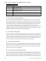
Table of Contents
Preface........................................................................................................................................... i
Chapter 1
Introduction........................................................................................................... 1-1
1.1
DOP Series Human Machine Interface ...................................................................................... 1-1
1.2
Features ..................................................................................................................................... 1-1
1.3
Ordering Information................................................................................................................... 1-3
1.4
Caution ....................................................................................................................................... 1-4
Chapter 2
Creating and Editing Screens............................................................................... 2-1
2.1
ScrEdit (Screen Editor) Setup .................................................................................................... 2-1
2.2
How to Start ScrEdit ................................................................................................................... 2-5
2.3
Menu Bar and Toolbar (File) ...................................................................................................... 2-12
2.4
Menu Bar and Toolbar (Edit) ...................................................................................................... 2-23
2.5
Menu Bar and Toolbar (View) .................................................................................................... 2-31
2.6
Menu Bar and Toolbar (Element) ............................................................................................... 2-43
2.7
Menu Bar and Toolbar (Screen)................................................................................................. 2-52
2.8
Menu Bar and Toolbar (Tools) ................................................................................................... 2-63
2.9
Menu Bar and Toolbar (Options)................................................................................................ 2-91
2.10 Menu Bar and Toolbar (Window) ............................................................................................... 2-122
2.11 Menu Bar and Toolbar (Help)..................................................................................................... 2-126
Chapter 3
Element Function ................................................................................................. 3-1
3.1
How to Choose Element............................................................................................................. 3-1
3.2
Button Element ........................................................................................................................... 3-3
3.3
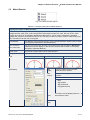
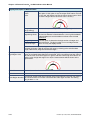
Meter Element ............................................................................................................................ 3-19
3.4
Bar Element................................................................................................................................ 3-21
Revision Apr. 30th, 2007, 2007PDD23000002
Table of Contents_ScrEdit Software User Manual
3.5
Pipe Element .............................................................................................................................. 3-24
3.6
Pie Element ................................................................................................................................ 3-27
3.7
Indicator...................................................................................................................................... 3-29
3.8
Data Display ............................................................................................................................... 3-32
3.9
Graph Display............................................................................................................................. 3-38
3.10 Input Element ............................................................................................................................. 3-46
3.11 Curve Element............................................................................................................................ 3-52
3.12 Sampling Element ...................................................................................................................... 3-60
3.13 Alarm Element ............................................................................................................................ 3-68
3.14 Graphic Element......................................................................................................................... 3-73
3.15 Keypad Element ......................................................................................................................... 3-81
Chapter 4
Macro Function..................................................................................................... 4-1
4.1
Macro Type................................................................................................................................. 4-2
4.2
Macro Editing.............................................................................................................................. 4-7
4.3
Macro Operation......................................................................................................................... 4-14
4.4
Error Messages .......................................................................................................................... 4-42
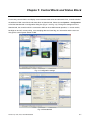
Chapter 5
Control Block and Status Block ............................................................................ 5-1
5.1
Control Block .............................................................................................................................. 5-2
5.2
Status Block................................................................................................................................ 5-9
Chapter 6
Internal Memory ................................................................................................... 6-1
Chapter 7
Example Explanation............................................................................................ 7-1
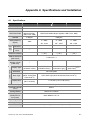
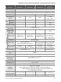
Appendix A Specifications and Installation .............................................................................. A-1
A.1 Specifications ............................................................................................................................. A-1
A.2 Dimensions and Profile .............................................................................................................. A-5
A.3 Installation .................................................................................................................................. A-10
Revision Apr. 30th, 2007, 2007PDD23000002
Table of Contents_ScrEdit Software User Manual
Appendix B USB Flash Drive Function .................................................................................... B-1
Appendix C Main Menu Operation of HMI System .................................................................. C-1
Revision Apr. 30th, 2007, 2007PDD23000002
Table of Contents_ScrEdit Software User Manual
About this Manual…
User Information
Be sure to store this manual in a safe place.
Due to constantly growing product range, technical improvement and alteration or changed texts, figures and
diagrams, we reserve the right of this manual contained information change without prior notice.
Coping or reproducing any part of this manual, without written consent of Delta Electronics Inc. is prohibited.
Technical Support and Service
Welcome to contact us or visit our web site (http://www.delta.com.tw/industrialautomation/) if you need any
technical support, service and information, or, if you have any question in using the product. We are looking
forward to serve you needs and willing to offer our best support and service to you. Reach us by the
following ways.
ASIA
JAPAN
DELTA ELECTRONICS, INC.
DELTA ELECTRONICS (JAPAN) INC.
TAOYUAN Plant/
Sales Office/
31-1, SHIEN PAN ROAD, KUEI SAN
DELTA SHIBADAIMON BLDG.
INDUSTRIAL ZONE TAOYUAN 333, TAIWAN
2-1-14 SHIBADAIMON, MINATO-KU,
TEL: 886-3-362-6301
TOKYO, 105-0012, JAPAN
FAX: 886-3-362-7267
TEL: 81-3-5733-1111
FAX: 81-3-5733-1211
NORTH/SOUTH AMERICA
EUROPE
DELTA PRODUCTS CORPORATION
DELTRONICS (NETHERLANDS) B.V.
Sales Office/
Sales Office/
P.O. BOX 12173
DE WITBOGT 15, 5652 AG EINDHOVEN,
5101 DAVIS DRIVE,
THE NETHERLANDS
RESEARCH TRIANGLE PARK, NC 27709, U.S.A.
TEL: 31-40-259-2860
TEL: 1-919-767-3813
FAX: 31-40-259-2851
FAX: 1-919-767-3969
Revision Apr. 30th, 2007, 2007PDD23000002
Chapter 1 Introduction
1.1
DOP Series Human Machine Interface
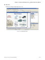
DOP series HMI are manufactured by adopting high-speed hardware to provide you with a powerful
programmable interface. ScrEdit software is a user-friendly program editor of DOP-A, DOP-AE and DOP-AS
series HMI for Windows. Please refer to the following section for its features and function introduction.
1.2
Features
PLC Serial Drives Support
DOP series HMI’s support more than twenty brands of PLC’s, including Delta, Omron, Siemens,
Mitsubishi, etc. All of the newly supported PLC’s communication protocol information could be found on
our website (http://www.delta.com.tw/industrialautomation/) for upgrade to meet your requirements. (All
other trademarks in this manual are property of their respective companies.)
Windows® Fonts Support for ScrEdit Software
Except Simplified Chinese, traditional Chinese and English languages, ScrEdit software also provides
those fonts that Windows® uses.
Quick Execution and Communication Macro
It can handle complicated calculation by executing macro. The user can also write communication
protocol with communication macro command to connect specific system via COM port.
Rapid USB Upload/Download
It will shorten upload/download time by using USB Ver1.1.
Recipes
It provides useful recipe editor that is similar to Microsoft excel for user to edit recipe easily and input
multiple recipes simultaneously (size limit is 64K). When downloading multiple recipes at the same time,
it can exchange by internal memory of HMI. If data has finished editing when downloading, you can
download recipe individually.
Direct Communication with Two or Three PLCs
DOP-A series HMI is able to connect to two different or the same controllers via two communication
ports. Up to three communication ports are provided in DOP-AE and DOP-AS series HMI for direction
connection to PLCs.
Revision Apr. 30th, 2007, 2007PDD23000002
1-1
Chapter 1 Introduction_ScrEdit Software User Manual
Support Multiple PLC’s Connections
One DOP series HMI can connect to multiple controllers in serial through COM2 of RS-485 port (NOTE 1).
Simulation Function (NOTE 2)
HMI ScrEdit software provides simulation feature which allows the user to develop and debug software
on the PC connected to DOP series HMI before downloading it to DOP series HMI.
Off-line Simulation: When the editing and compile operation is completed, the user can use off-line
simulation function to simulate HMI operation and check if it is correct or not through the PC directly
without connecting to the controller.
On-line Simulation: When the editing and compile operation is completed, the user can use on-line
simulation function to simulate HMI operation and check if it is correct or not through the PC directly with
connecting to the controller.
Using SM Card to Backup Data
SM card can also be used to backup data or transfer data to another HMI. After data transmission, the
data can be saved into the FLASH memory of HMI. History list and alarm message can be also saved in
SM card and the user can read these files by card reader for collecting data and printing.
Multiple Security Protection
It provides passwords to protect designer’s intellectual property rights and also for the user to set the
user’s priority for important components. Only the user, whose priority is higher than the component, can
use the component.
USB Host Port (USB Host) Equipped
Parts of DOP series HMIs have a built-in USB Host interface for the connection to USB flash drive, card
reader and printer with USB socket. The user can save data, copy program and print the screen
immediately and increase the data storage space.
Multiple Security Protection
It provides passwords to protect designer’s intellectual property rights and also for user to set user
priority for important component.
Multi-Language Support
It is easy for the user to switch the desired language via HMI or the external controller. Furthermore,
Unicode editing is supported, and therefore it is convenient for the user to create and edit more quickly.
1-2
Revision Apr. 30th, 2007, 2007PDD23000002
Chapter 1 Introduction_ScrEdit Software User Manual
NOTE
1)
The controller should provide RS-485 interface.
2)
Off-line/On-line simulation functions are only provided for some parts of the controllers. Also, the
execution time of on-line simulation only can continue 30 minutes. After the simulation time has
finished, HMI will return ScrEdit software main screen from simulation window automatically.
3)
When executing simulation function, the resolution of PC screen should be set to 24bit and higher,
otherwise the simulation function may work abnormally.
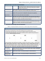
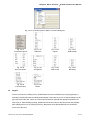
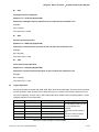
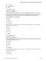
1.3
Ordering Information
DOP
–
AE
10
TH
T
D
2
3
4
5
6
1
–
W
7
1. Product Name
Delta Operation Panel
2. Series
AS: USB Client, USB Host, COM Port x 3
A: USB Client, COM Port x 2
AE: USB Client, USB Host, COM Port x 3, Extension Port
3. Panel Size
38: 3.8 inches
57: 5.7 inches
75: 7.5 inches
80: 8 inches
94: 9.4 inches
10: 10.4 inches
4. Panel Color and Type
BS: Blue/White 16 Grays STN
GS: Black/White 16 Grays FSTN
CS: 256 Colors STN
TC: 256 Colors TFT
TH: 65536 Colors TFT
5. Interface Type
T: Touch Panel
6. Input Power
D: DC +24V
7. Case Color
None: Gray
W: White (currently be provided for AS38, A57 and AE57 models only)
Revision Apr. 30th, 2007, 2007PDD23000002
1-3
Chapter 1 Introduction_ScrEdit Software User Manual
1.4
Caution
Operation Environment (temperature and humidity)
HMI should be operated in the following environment parameters to adjust screen brightness and
contrast to get the best image. If operating out of the range, LCD may be improperly displayed when
using for long time.
Ambient Operating Temperature: 0 ºC to 50 ºC (32 ºF to 122 ºF)
Relative Humidity: 10% ~ 90%, no condensation allowed
SM Card
SM card can be used to save and transmit data. Only SM card that formatted by HMI can be used on
both HMI and Windows® OS system. (Even it can be read/written in some format, but faults may occur
due to different format among Win95/98/2000/XP versions)
USB Flash Drive
USB flash drive can be used to save data. It also can be used to copy data from HMI and its format is
FAT32. When using USB flash drive to save data, we recommend the user should enter system screen
first and then remove the USB flash drive. Follow this process can ensure that the data is saved
completely in USB flash drive.
1-4
Revision Apr. 30th, 2007, 2007PDD23000002
Chapter 2 Creating and Editing Screens
2.1
ScrEdit (Screen Editor) Setup
In this chapter, it will introduce general functions of Screen Editor with Windows. The user can use it to
design what he wants. Detail information for each function will be discussed in following chapters.
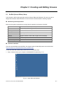
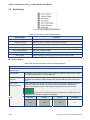
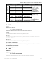
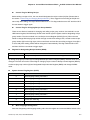
Minimum System Requirement
Below are the system requirements to comply with the operation environment of ScrEdit:
Item
System Requirement
CPU
Pentium III, 500MHz or greater is recommended
Memory
256MB and above is recommended
Hard Disk
Capacity: 400MB and above
Monitor
Support resolution: 800 600 or higher full-color display.
Printer
Printer compatible with Windows® 2000 & Windows® XP
Operation System
Windows® 2000 & Windows® XP
Software installation
The user can download the Screen Editor, the program editor of Delta HMI product via the link below:
http://www.delta.com.tw/product/em/hmi/hmi_software.asp.
To start the Delta HMI ScrEdit setup, please refer to the following steps:
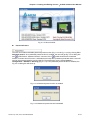
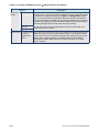
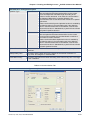
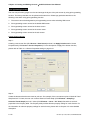
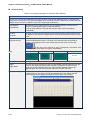
1. Step 1: Please start-up your computer to Win2000/WinXP system (Fig. 2.1.1).
Fig. 2.1.1 Open Microsoft Windows
Revision Apr. 30th, 2007, 2007PDD23000002
2-1
Chapter 2 Creating and Editing Screens_ScrEdit Software User Manual
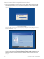
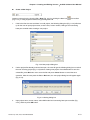
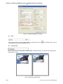
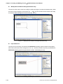
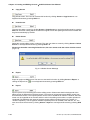
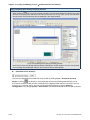
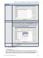
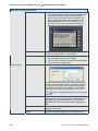
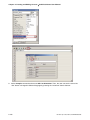
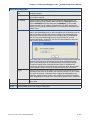
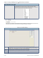
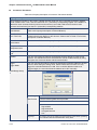
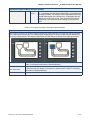
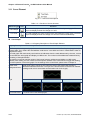
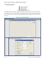
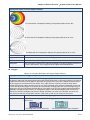
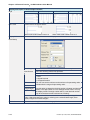
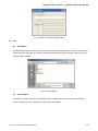
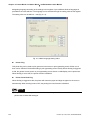
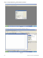
2. Step 2: Execute setup.exe from Windows taskbar by clicking “Start” > “Run”. 3. After pressing OK,
system will setup automatically and you will get the following dialog box to select the desired display
language (Fig. 2.1.2).
Fig. 2.1.2 Select Language
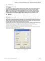
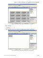
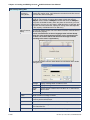
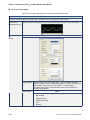
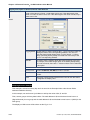
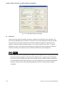
After pressing OK, system will setup automatically and you will get the following dialog box to choose
destination location (Fig. 2.1.3).
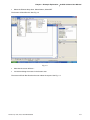
Fig. 2.1.3 Directory for installing ScrEdit
To select the default directory C: \Program File\Delta\Screen Editor 1.05.XX\, click Next> for the next
step. Setup will install in the directory indicated in the Destination Directory box at the bottom of the
dialog box.
2-2
Revision Apr. 30th, 2007, 2007PDD23000002
Chapter 2 Creating and Editing Screens_ScrEdit Software User Manual
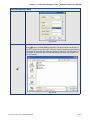
To select a directory other than the default directory, click Browse. A list of available directories appears.
Highlight the desired directory for the Delta HMI ScrEdit and click OK, then Next> for the next step.
If necessary, click < Back button to take you back through Setup dialog boxes one by one.
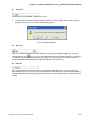
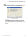
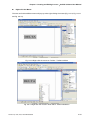
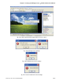
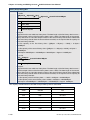
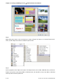
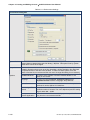
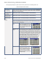
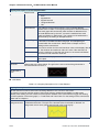
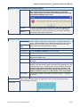
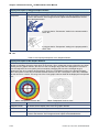
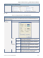
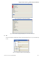
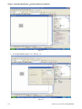
3. Step 3: After pressing Next, system will ask you to select the installation software, i.e. ScrEdit (Fig.
2.1.4).
Fig. 2.1.4 Select ScrEdit
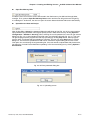
4. Step 4: Then click Install button to start ScrEdit installation (Fig. 2.1.5).
Fig. 2.1.5 Starting ScrEdit installation
Revision Apr. 30th, 2007, 2007PDD23000002
2-3
Chapter 2 Creating and Editing Screens_ScrEdit Software User Manual
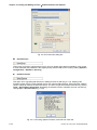
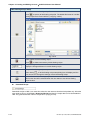
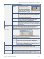
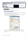
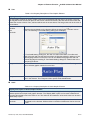
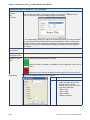
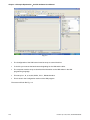
Fig. 2.1.6 Finish installing ScrEdit
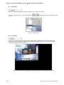
5. Step 5: After finish installing ScrEdit (Fig. 2.1.6), system will ask you to install HMI USB driver, please
click Yes to install.
Fig. 2.1.7 Install HMI USB driver
6. Step 6: After installing HMI USB driver, click Close to complete the installation.
2-4
Revision Apr. 30th, 2007, 2007PDD23000002
Chapter 2 Creating and Editing Screens_ScrEdit Software User Manual
2.2
1.
How to Start ScrEdit
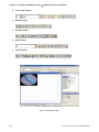
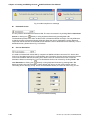
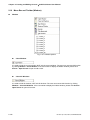
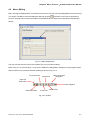
After setup, you can start ScrEdit by clicking Screen Editor 1.05.XX shortcut on the desk (Refer to Fig.
2.2.1) or from Windows taskbar, click Start > Programs > Delta > Screen Editor 1.05.XX.
Fig. 2.2.1
Fig. 2.2.2 Start-up display
Revision Apr. 30th, 2007, 2007PDD23000002
2-5
Chapter 2 Creating and Editing Screens_ScrEdit Software User Manual
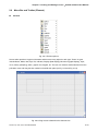
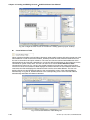
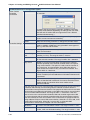
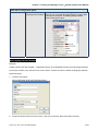
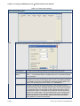
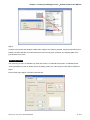
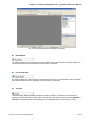
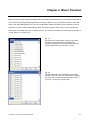
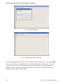
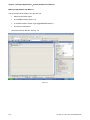
When ScrEdit is activated for the first time, the first window to show up is as follows. There are only File (F),
View(V), Option(O) and Help(H) on the toolbar.
Fig. 2.2.3 Screen without editing file
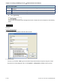
2.
After pressing
or click File > New, it can create a new project and you will get a dialog box as
shown in the following. (Fig. 2.2.4)
Fig. 2.2.4 Creating a New project
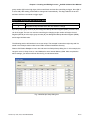
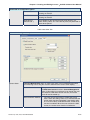
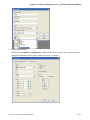
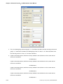
3.
Enter the Project Name, Screen Name, Screen No. and select connected HMI, controller or printer.
Then, click OK. It can create a new project in ScrEdit as shown in the following. (Fig. 2.2.5)
2-6
Revision Apr. 30th, 2007, 2007PDD23000002
Chapter 2 Creating and Editing Screens_ScrEdit Software User Manual
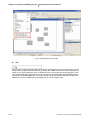
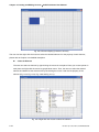
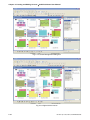
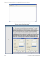
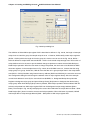
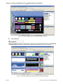
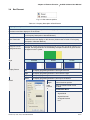
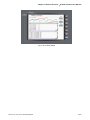
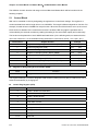
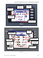
Fig. 2.2.5 New project screen of ScrEdit
There are five parts in the following for ScrEdit editing window.
Menu Bar
There are nine functions for selection: File, Edit, View, Element, Screen, Tools, Options, Window, and
Help.
Toolbar
Toolbar (Fig. 2.2.6) is like those toolbar in Windows® program. It is easy to use for editing and the user
can arrange its position freely. For example, the user can move the Toolbar to the left side of the screen.
Also, the user can arrange the toolbar position by their usage. The followings are the available toolbar on
ScrEdit.
1. Standard Toolbar
2. Zoom Toolbar
Revision Apr. 30th, 2007, 2007PDD23000002
2-7
Chapter 2 Creating and Editing Screens_ScrEdit Software User Manual
3. Text Format Toolbar
4. Bitmap Toolbar
5. Element Toolbar
6. Build Toolbar
7. Layout Toolbar
Fig. 2.2.6 ScrEdit Toolbar
2-8
Revision Apr. 30th, 2007, 2007PDD23000002
Chapter 2 Creating and Editing Screens_ScrEdit Software User Manual
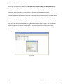
Fig. 2.2.7 Move ScrEdit toolbar to the left side of the screen
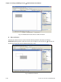
Property Table
It provides element property settings for each element (Fig. 2.2.8 & Fig. 2.2.9). Please refer to Chapter 3
for detailed description.
Element state selection
All elements on current
editing screen
Fig. 2.2.8 Property table
Revision Apr. 30th, 2007, 2007PDD23000002
2-9
Chapter 2 Creating and Editing Screens_ScrEdit Software User Manual
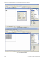
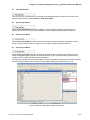
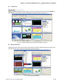
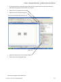
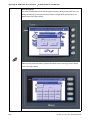
Fig. 2.2.9 Editing screen preview
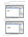
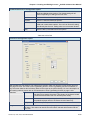
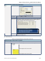
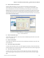
Output Window
All editing actions and output message when compile function is enabled will be shown here (Fig. 2.2.10).
When compiling, ScrEdit will detect the error of user program automatically. Once error occurs, the
correspondent message will display in output window. Click error message to get error element window.
Fig. 2.2.10 Output window
2-10
Revision Apr. 30th, 2007, 2007PDD23000002
Chapter 2 Creating and Editing Screens_ScrEdit Software User Manual
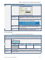
Work Place
Following is an editing example display (Fig. 2.2.11).
Fig. 2.2.11 ScrEdit Work Place
Revision Apr. 30th, 2007, 2007PDD23000002
2-11
Chapter 2 Creating and Editing Screens_ScrEdit Software User Manual
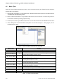
2.3
Menu Bar and Toolbar (File)
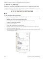
ScrEdit provides the convenient pull-down Menu and makes it easy for the user to create, edit and manage
includes elements, pictures, graphs, macro program, recipes and displays in DOP series HMI. The pull-down
menu options of Menu bar are described as follows:
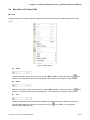
File
The “File” menu performs many common functions.
1. Allows user to create new project, open old project, close file, save current file and save current file
to another file name, etc. options.
2. Make and Open external memory data (Ext. Memory Data).
3. Upload the editing display and data of DOP series HMI to PC and save to hard disk.
4. Update the firmware of DOP series HMI.
5. Password protection function.
6. Screen print, print preview and print setup functions.
7. By default, ScrEdit presents a list of the most recent used files on the File menu for quick access.
Just click the file name to open the file.
8. Exit command is to close all open editing files and offer to save those which have not been save
yet and finally exit the ScrEdit.
Fig. 2.3.1 File options
2-12
Revision Apr. 30th, 2007, 2007PDD23000002
Chapter 2 Creating and Editing Screens_ScrEdit Software User Manual
Create a New Project
Creates a new project by choosing File > New (Fig. 2.3.2) or clicking the New icon
(Fig. 2.3.3), or using keyboard shortcuts by pressing Ctrl + N.
1.
from toolbar
If this is the first time use and there is no old project, the following dialog box (Fig. 2.3.2) will show
up for the user to input project name, screen name, screen number, HMI type and connecting
base port controller after creating a new project.
Fig. 2.3.2 New project dialog box
2.
If other project files already exist and are open, the user will get the following dialog box to remind
the user of saving project (Fig. 2.3.3) before creating new project. Press Yes button to save the
existed file, press No button not to save the file and press Cancel button to cancel the save
operation. After the user press the Yes or No button, the new project dialog box will appear again
(Fig. 2.3.2).
Fig. 2.3.3 Saving dialog box
3.
Input project name, screen name, select HMI model and connecting base port controller (Fig.
2.3.4), and then press OK button.
Revision Apr. 30th, 2007, 2007PDD23000002
2-13
Chapter 2 Creating and Editing Screens_ScrEdit Software User Manual
Fig. 2.3.4 HMI model and base port controller options
Open Old Project
Open current project by choosing File > Open (Fig. 2.3.7) or clicking the Open icon
or using keyboard shortcuts by pressing Ctrl + O.
1.
from toolbar,
If other project files exist before opening an old project, the user will get the Saving dialog box (Fig.
2.3.3) to remind the user of saving file and then get the following dialog box for opening existing
dop file (Fig. 2.3.5).
2.
If save operation is complete or there is no old project files, the following dialog box for opening
existing dop file (Fig. 2.3.5) will show up directly.
Fig. 2.3.5 Open an old project in ScrEdit
2-14
Revision Apr. 30th, 2007, 2007PDD23000002
Chapter 2 Creating and Editing Screens_ScrEdit Software User Manual
Close File
Closes project by clicking File > Close (Fig. 2.3.10).
1. If project didn’t get saved before issuing the command of closing project, the user will get saving
dialog box (Fig. 2.3.6) to remind the user of saving project.
Fig. 2.3.6 Saving dialog box
Save File
Save current project into hard disk with extension file “dop” by choosing File > Save (Fig. 2.3.12) or
clicking the Save icon
(Fig. 2.3.13), or using keyboard shortcuts by pressing Ctrl + S. If the project
is a new file, the Save as dialog box will show up (Fig. 2.3.15). If the project is an old file, the Save
function will perform immediately and the Save as dialog box will not show up.
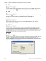
Save As
Save current project to another file name by clicking File > Save As (Fig. 2.3.14). The user will get
Save as dialog box (Fig. 2.3.15) to input project name with extension file dop. This dialog also appears
automatically when the first time any project file is saved no matter whether Save As or Save command
is used.
Revision Apr. 30th, 2007, 2007PDD23000002
2-15
Chapter 2 Creating and Editing Screens_ScrEdit Software User Manual
Fig. 2.3.7 Save as dialog box (Dialog box that let user input project name to save as.)
Make Ext. Memory Data
Before using this command, ensure to compile the editing screen data. If not execute the compilation
first, the ScrEdit cannot make screen data and an error message dialog box will show up (Fig. 2.3.8).
Please execute the compilation first and then clicking File > Make Ext. Memory Data to copy the
compiled HMI program into SM card (Fig. 2.3.9) or a USB flash drive. If the SM card or USB flash drive
with compiled HMI program stored inside is inserted into HMI, HMI will startup by reading the data of
SM card or USB flash drive directly.
Fig. 2.3.8 Error message dialog box when
making Ext. Memory Data
Fig. 2.3.9 Make Ext. Memory Data Dialog Box
2-16
Revision Apr. 30th, 2007, 2007PDD23000002
Chapter 2 Creating and Editing Screens_ScrEdit Software User Manual
Open Ext. Memory Data
In HMI, the user can move the screen data saved in the flash memory into SM card through folder
manager. Then, perform Open Ext. Memory Data function and the user will get the user will get Fig.
2.3.9 dialog box. At this time, the user can open the screen data and edit the HMI screen data directly.
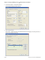
Upload Screen Data and Recipe
After clicking File > Upload, the password dialog box will show up first (Fig. 2.3.10), the user needs to
input password (the password is the highest priority saved in HMI, which is set by clicking Options >
Configuration > Standard > Security). When entering the correct password, the user can get save as
dialog box (Fig. 2.3.7). After inputting project file name, the uploading will start (Fig. 2.3.11). The user
can get the progress with progress box and stop uploading by clicking Stop button. When progress
goes to 100%, it indicates that the uploading is complete. The user can press Stop button to exit the
dialog box. The file that is uploaded from HMI can be restored to original editing file for user to edit.
This option is to avoid losing the original editing file. If the user wants to upload data with pictures also,
just select the “Include Picture Data when uploading” in Environment dialog box by clicking Options >
Environment.
Fig. 2.3.10 Enter password dialog box
Fig. 2.3.11 Uploading screen
Revision Apr. 30th, 2007, 2007PDD23000002
2-17
Chapter 2 Creating and Editing Screens_ScrEdit Software User Manual
Fig. 2.3.12 Environment dialog box
Upload Recipe
This function is similar to upload function but it can only upload recipe. Before uploading, it also needs
to enter password (the password is the highest priority saved in HMI, which is set by clicking Options >
Configuration > Standard > Security).
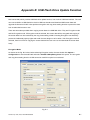
Update Firmware
This option is for upgrading HMI firmware or adding function for HMI (Fig. 2.3.13). Keeping HMI
firmware version to be the most updated version can optimize HMI operation. Ensure that the software
version of ScrEdit matches the firmware version. The user can get the firmware information by clicking
Tools > Get Firmware Information. Regarding the software version of ScrEdit, the user can find it by
clicking Help > About ScrEdit (Fig. 2.3.14).
Fig. 2.3.13 Choosing Update Firmware command from menu bar
2-18
Revision Apr. 30th, 2007, 2007PDD23000002
Chapter 2 Creating and Editing Screens_ScrEdit Software User Manual
Fig. 2.3.14 About ScrEdit
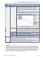
Password Protect
The user can enable and disable password protect function (Fig. 2.3.15 & Fig. 2.3.16) by clicking File >
Password protect. Once password protect function is enabled, the user will get Fig. 2.3.15 dialog box
and
symbol before “Password Protect” command. If the
symbol shows before “Password
Protect” command from File menu, it indicates that this dop file is password protected and the user will
need to input password before opening dop file. The password is set by clicking Options >
Configuration > Standard > Security) (Fig. 2.3.17). If the password protect function is disabled, the
Fig. 2.3.16 dialog box will show up.
Fig. 2.3.15 Password protect function is enabled
Fig. 2.3.16 Password protect function is disabled
Revision Apr. 30th, 2007, 2007PDD23000002
2-19
Chapter 2 Creating and Editing Screens_ScrEdit Software User Manual
Fig. 2.3.17 Password settings - Security
Print
Print current screen by choosing File > Print, or clicking the Print icon
using keyboard shortcuts by pressing Ctrl + P.
from toolbar (Fig. 2.3.28), or
Print Preview
Select this function by clicking File > Print Preview. Using this function can preview the full page after
printing (Fig. 2.3.18).
Fig. 2.3.18 Print Preview screen
2-20
Revision Apr. 30th, 2007, 2007PDD23000002
Chapter 2 Creating and Editing Screens_ScrEdit Software User Manual
Print Setup
Printer and paper settings. Select this function by clicking File > Print Setup. Using this function can set
the property of printer, print paper and print direction, etc. several functions (Fig. 2.3.19).
Fig. 2.3.19 Print Setup dialog box
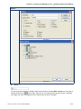
File Quick Access
By default, ScrEdit presents a list of the four most recent used files on the File menu for quick
access (Fig. 2.3.20). Just click the file name to open the file. This function is similar to the Open
command and the user can refer to the description of Open command on the page 2-14. If the
saving path is too long, the too long path will display as “….”. The user still can see the complete
dop file name.
Revision Apr. 30th, 2007, 2007PDD23000002
2-21
Chapter 2 Creating and Editing Screens_ScrEdit Software User Manual
Fig. 2.3.20 Most recent used files
Exit
Exit function is to close all open editing files and offer to save those that have not been save yet and
finally exit the ScrEdit. Select this function by clicking File > Exit. If the file has been changed or not
saved yet, the saving dialog box (Fig. 2.3.6) will show up to remind the user of saving project. If the
user press Cancel button at this time, the exit command is cancelled. Either pressing Yes button to
save the file, or pressing No button not to save the file can exit the ScrEdit. After the user press the
Yes button, the Save As dialog box will appear (Fig. 2.3.7) for saving the file.
2-22
Revision Apr. 30th, 2007, 2007PDD23000002
Chapter 2 Creating and Editing Screens_ScrEdit Software User Manual
2.4
Menu Bar and Toolbar (Edit)
Edit
Adopt pull-down menu similar to Microsoft Office style and provide user-friendly Edit pull-down menu (Fig.
2.4.1).
Fig. 2.4.1 Edit options
Undo
Undo the last action. Select this function by choosing Edit > Undo or clicking the Undo icon
from
toolbar, or use keyboard shortcuts by pressing Ctrl + Z. All actions are recorded in output window.
Redo
Redo the undo action. Select this function by choosing Edit > Redo or clicking the Redo icon
from
toolbar, or use keyboard shortcuts by pressing Ctrl + Y. All actions are recorded in output window.
Cut
Deletes the selected element and save it in clipboard to paste to other place. Select this function by
choosing Edit > Cut from menu bar or clicking the Cut icon
shortcuts by pressing Ctrl + X.
Revision Apr. 30th, 2007, 2007PDD23000002
from toolbar, or use keyboard
2-23
Chapter 2 Creating and Editing Screens_ScrEdit Software User Manual
Copy
Copy the selected element to the clipboard. Select this function by choosing Edit > Copy from menu
bar or clicking the Copy icon
from toolbar, or use keyboard shortcuts by pressing Ctrl + C.
Paste
Paste element from clipboard. Select this function by choosing Edit > Paste from menu bar or clicking
the Paste icon
from toolbar, or use keyboard shortcuts by pressing Ctrl + V.
Delete
Delete selected element. Select this function by choosing Edit > Delete from menu bar or use
keyboard shortcuts by pressing Del.
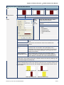
Select All
It is used to select all elements. Select this function by choosing Edit > Select All from menu bar or
use keyboard shortcuts by pressing Ctrl + A. When selecting all, the last created element, i.e. the
picture on the top will be a square that is filled with blue color and the border is in white. The other
created elements will be in white color and the border is in black. This is to provide a reference for Align
and Make Same Size function. When there are two and more elements, one element should be the
base element. The base element is used to align or resize.
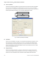
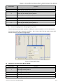
Find
It is used to find the content matches the find criteria. Select this function by choosing Edit > Find from
menu bar or use keyboard shortcuts by pressing Ctrl + F. The user can find element text, read
address, write address or memory address in current screen, or all screens (Fig. 2.4.2). Once it finds,
the result of find content will be shown in the output window. Click some of the result of find content, it
will jump to its location in ScrEdit (Fig. 2.4.3).
Fig. 2.4.2 Find option
2-24
Revision Apr. 30th, 2007, 2007PDD23000002
Chapter 2 Creating and Editing Screens_ScrEdit Software User Manual
Find
Find What
This field is where the user enters the word or phase that the user is looking for
Options
Current Screen
This causes ScrEdit to navigate the current screen only and find the
matching word or phase that the user is looking for. The output
window will display all matching words or phases. When the user
double clicks the word or phase, ScrEdit will jump to that location of
the matching word or phase. Please refer to the example screen
below.
Fig. 2.4.3
Type
Check Box
All Screen
This causes ScrEdit to navigate all screens and find the word or phase
that the user is looking for. The output window will display all matching
words or phases. When the user double clicks the word or phase,
ScrEdit will also jump to that location of the matching word or phase.
Text
This causes ScrEdit to find the text.
Read Address
This causes ScrEdit to find the read address.
Write Address
This causes ScrEdit to find the write address.
All Address
This causes ScrEdit to find the read and write address.
If “Match whole word only” box is checked, only the exact word or phase that the user
types will be found. If “Match whole word only” box is not checked, all words that contain
the word or phase that the user types will be found.
If “Support Multi-Language Finding” box is checked, all multi language words that contain
the word or phase that the user types will be found. However, “Support Multi-Language
Finding” option can only be enabled when the find content type is text.
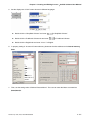
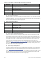
Replace
It is used to replace the content (Fig. 2.4.4). Using this command can replace text, read address and
write address in current screen or all screens. Its function is very similar to Find command expect that it
not only can find the word or phase that the user is looking for but also can replace it with a new entry.
The replace content type could be text, read and write address and the replace content data type could
be Bit, Word or Double Word. The function of replace content data type is enabled only when the
replace content type is either read or write address. Select this function by choosing Edit > Replace
from menu bar or use keyboard shortcuts by pressing Ctrl + R.
Revision Apr. 30th, 2007, 2007PDD23000002
2-25
Chapter 2 Creating and Editing Screens_ScrEdit Software User Manual
Fig. 2.4.4 Replace option
Replace
Find What
This field is where the user enters the word or phase that the user is looking for
Replace With This field is where the user enters the word or phase that the user wants to replace with
Options
Type
Data Type
Current Screen This causes ScrEdit to navigate the current screen only, find the matching
word or phase that the user is looking for and replace it.
All Screen
This causes ScrEdit to navigate all screens and find the matching word or
phase that the user is looking for and replace it.
Text
This causes ScrEdit to find and replace the text.
Read Address
This causes ScrEdit to find and replace the read address.
Write Address
This causes ScrEdit to find and replace the write address.
Bit
The function of replace content data type is enabled only when the
replace content type is either read or write address. The replace content
data type could be Bit, Word or Double Word.
WORD
DWORD
Filter
Element
Macro
This option is available when the replace content is read and write
address. There are six options for selection, Element, Macro, Control &
Status, History, Alarm and Recipe.
Control &
Status
History
Alarm
Recipe
Replace
Replace All
2-26
Replace button is used to replace the word or phase that the user types and find and
select the next one. For example, the user wants to replace the read address from $0 to
$1234, enter $0 in Find What field, enter $1234 in Replace With field and press Replace
button (Fig. 2.4.5). ScrEdit will find the matching address (Fig. 2.4.6) and the user can
select which the address of the element should be replaced. Replace All button is used to
replace all found matching words automatically.
Revision Apr. 30th, 2007, 2007PDD23000002
Chapter 2 Creating and Editing Screens_ScrEdit Software User Manual
Replace
Fig. 2.4.5
Fig. 2.4.6
Group
It is used to group elements in ScrEdit. Select this function by choosing Edit > Group from menu bar or
from toolbar. When two or more elements are grouped, it will be regarded
clicking the Group icon
as a single unit and move together but the element size cannot be changed.
Revision Apr. 30th, 2007, 2007PDD23000002
2-27
Chapter 2 Creating and Editing Screens_ScrEdit Software User Manual
Ungroup
It is used to ungroup elements in ScrEdit. Select this function by choosing Edit > Ungroup from menu
bar or clicking the Group icon
from toolbar.
Order
It is used to set and change the stacking order of the selected element. Select this function by
choosing Edit > Order from menu bar or clicking the Order icons
from toolbar.
Bring to Front. Move the selected element to the front of all other elements.
Send to Bottom. Move the selected element behind all other elements.
Bring Forward. Move the selected element forward one position.
Send Backward. Move the selected element behind one position.
Align
It is used to align the element. The user can select this function by choosing Edit > Align from menu
bar or clicking the Align icons from toolbar.
The Align icons includes:
: Align Left;
: Align Right;
: Center Vertically;
: Align Top;
: Align Bottom;
: Center Horizontally;
: Across Space Evenly;
: Down Space Evenly.
Align Left, Align Right, Align Top and Align Bottom commands are available when two or more
elements are selected. That is because the element only can be left, right, top and bottom aligned
relative to another element. Align Vertical Center and Align Horizontal Center commands are available
when one or more elements are selected. Across Space Evenly and Down Space Evenly are available
when three or more elements are selected.
After Align commands are used, the coordinates of the elements will changed to the coordinates of the
new position.
Center Vertically: Set the element to be the vertical position of the work place.
Center Horizontally: Set the element to be the horizontal position of the work place.
Across Space Evenly: Make all the elements align in a consistent width.
Down Space Evenly: Make all the elements align in a consistent height.
Make Same Size
It is used to make the element to be the same size. The user can select this function by choosing Edit
> Make Same Size from menu bar or clicking the Make Same Size icons from toolbar.
This function is available only when two or more elements are selected. The user has to select one
element first and treat it as standard, and use this command to make other two or more elements to be
the same size.
2-28
Revision Apr. 30th, 2007, 2007PDD23000002
Chapter 2 Creating and Editing Screens_ScrEdit Software User Manual
Text Process
It is used to set and change text direction and import text in ScrEdit. The user can select this function
by choosing Edit > Text Process from menu bar or clicking the Text Process icons from toolbar.
next to the Text Process command represents that this function is enabled. In the Import Text
dialog box, the user can decide if use Text Bank Edit Font or not. If the user checks the box next to
Text Bank Edit Font, the imported text will be display by adopting the fonts of Text Bank. For the
settings of Text Bank, please refer to Option > Text Bank.
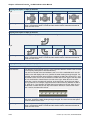
Duplicate
It allows the user to copy one or more elements horizontally and vertically at the same time. After
selecting this function by choosing Edit > Duplicate from menu bar, the Fig. 2.4.7 dialog box will show
up. The user can enter the number of columns and rows to get the total copy numbers. If the user only
wants to copy the number of Rows, please uncheck the box next to Columns. If the user only wants to
copy the number of Columns, please uncheck the box next to Rows.
Spacing (pixels): This option is used to set the spacing by horizontal or vertical direction between every
element. After this option is set, the duplicated elements will be placed in this spacing.
Increase / Decrease Address: This option is used to place the element that the user copies by
ascending or descending address. The unit of the address can be Word or Bit.
X-direction / Y-direction: This option is used to place the element that the user copies by horizontal (Xdirection) or vertical (Y-direction) direction.
Please refer to Fig 2-4-30 and Fig. 2-4-31 for example.
Fig. 2.4.7 Duplicate dialog box
Revision Apr. 30th, 2007, 2007PDD23000002
2-29
Chapter 2 Creating and Editing Screens_ScrEdit Software User Manual
Fig. 2.4.8 Duplicate Example 1
Fig. 2.4.9 Duplicate Example 2
2-30
Revision Apr. 30th, 2007, 2007PDD23000002
Chapter 2 Creating and Editing Screens_ScrEdit Software User Manual
2.5
Menu Bar and Toolbar (View)
View
Toolbars
Docking windows
Fig. 2.5.1 View options
In View option, the user can decide how toolbars and docking windows display. Once the user clicks on it, it
will have icon
in front of it and display on screen. The user can also arrange these toolbars and docking
windows by themselves. If
not show in front of the toolbar, it indicates that the toolbar is hided and not
display on the screen. The description of each toolbar is introduced in the following sections.
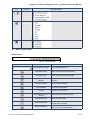
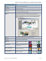
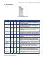
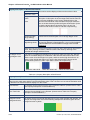
Standard Toolbar
Table 2.5.1 Standard toolbar
Icon
Function
Description
New
Create a new project
Open
Open an old project
Save
Save current edited project
Export
Export an project to BMP format
Undo
Undo an action (some can’t be undo)
Redo
Redo an action
Cut
Copy
Revision Apr. 30th, 2007, 2007PDD23000002
Cut selected elements
Copy selected elements
2-31
Chapter 2 Creating and Editing Screens_ScrEdit Software User Manual
Icon
Function
Description
Paste
Paste the element the user copy or cut
Find
Find specific text, write address or read address
New Screen
Create a new screen
Open Screen
Open an old screen
Print
Print current project
Help
Screen editor version
Status Bar
Display current editing states.
Fig. 2.5.2 Status bar
Text Format Toolbar
Table 2.5.2 Text toolbar
Icon
Function
2-32
Display and change text font
Align text to left
The space at the right/left sides of text will be the
same
Align Right
Align text to right
Align Top
Align text to top
Align Bottom
Font Name
Center Vertical
Display and change text size
Center Horizontal
Font Size
Align Left
Description
Text Color
The space at the top/bottom sides of text will be the
same
Align text to bottom
Change text color
Bold
Text bold
Italic
Text Italic
Underline
Add line under text
Revision Apr. 30th, 2007, 2007PDD23000002
Chapter 2 Creating and Editing Screens_ScrEdit Software User Manual
Bitmap Toolbar
Table 2.5.3 Bitmap toolbar
Icon
Function
Description
Select Transparent Remove the color of the picture and determine the transparent color
Color
of the picture
Chang Mode for
Process All State
Picture
If this function is enabled, not only the current picture with current
state but also all pictures with all states will be stretched, resized or
aligned
Picture Stretch All
Stretch the selected picture to the whole range of the element.
Picture Stretch 1: 1 Scale the picture relative to original picture size
Original Picture
Picture Align Left
Picture Center
Horizontal
Resize the selected picture to the actual picture size
Align the selected picture to left
The space at the right/left sides of the selected picture will be the
same
Picture Align Right Align the selected element to right
Picture Align Top
Picture Center
Vertical
Align the selected element to top
The space at the top/bottom sides of the selected element will be
the same
Picture Align Bottom Align the selected element to bottom
Element Toolbar
Table 2.5.4 Element toolbar
Icon
Function
Drop-down Menu
Button
Revision Apr. 30th, 2007, 2007PDD23000002
2-33
Chapter 2 Creating and Editing Screens_ScrEdit Software User Manual
Icon
Function
Drop-down Menu
Meter
Bar
Pipe
Pie
Indicator
Display
Movement
Input
Curve
History
2-34
Revision Apr. 30th, 2007, 2007PDD23000002
Chapter 2 Creating and Editing Screens_ScrEdit Software User Manual
Icon
Function
Drop-down Menu
Alarm
Graphic
Keypad
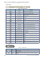
Build / Layout Toolbar
Build Toolbar
Table. 2.5.5 Build toolbar
Icon
Function
Current Element State
Description
Text on selected element
View State OFF/1
Switch and view current state OFF/1
View State ON/1
Switch and view current state ON/1
Display All Read/Write
Address
Display all read/write addresses of all
elements
Previous windows
Select previous windows
Next windows
Select the next windows
Compile
Compile current element
Download Screen and
Recipe
Download screen data and recipe
Download Screen
Download screen data
On-line Simulation
Test editing file at PC side and it needs to
connect to the controller
Off-line Simulation
Test editing file at PC side and it doesn’t
need to connect to the controller
Revision Apr. 30th, 2007, 2007PDD23000002
2-35
Chapter 2 Creating and Editing Screens_ScrEdit Software User Manual
Layout Toolbar
Table. 2.5.6 Layout toolbar
Icon
Function
Group
Ungroup
Group the selected elements
Ungroup the selected elements
Bring to Front
Move the selected element to the front of all
other elements
Send to Bottom
Move the selected element behind all other
elements
Bring Forward
Send Backward
Align Left
Move the selected element forward one
position
Move the selected element behind one position
Align the selected elements to left
Align Right
Align the selected elements to right
Align Top
Align the selected elements to top
Align Bottom
Description
Align the selected elements to bottom
Set the element to be the vertical position of
the work place
Center Vertically
Center Horizontally
Across Space Evenly
Make all the elements align in a consistent
width
Down Space Evenly
Make all the elements align in a consistent
height
Make Same Width
Make the selected elements to be the same
width
Make Same Height
Make the selected elements to be the same
height
Make Same Size
Make the selected elements to be the same
size
Set the element to be the horizontal position of
the work place
Zoom Toolbar
Table. 2.5.7 Zoom toolbar
Icon
Function
Description
Lets the user set a zoom level, including 25%, 50%, 75%, 100%, 150%,
Display Level 200% and 300%
2-36
Zoom In
Lets the user change the magnification level, including 150%, 200%
and 300%.
Revision Apr. 30th, 2007, 2007PDD23000002
Chapter 2 Creating and Editing Screens_ScrEdit Software User Manual
Icon
Function
Zoom Out
1:1
Description
Lets the user reduce the magnification level, including 25%, 50% and
75%.
Lets the user change element size to actual size (100%).
Property Table
Element property table. Please refer to Chapter 3 for detailed description.
Fig. 2.5.3 Property table
Output Window
All editing processes during compile operation will be shown here for user’s reference. It can let the
user know the result of the compile operation and it is also convenient for tracing error address when
creating and editing screen (See Fig. 2.5.4, Fig. 2.5.5, Fig. 2.5.6 and Fig. 2.5.7).
Fig. 2.5.4 Output window
Revision Apr. 30th, 2007, 2007PDD23000002
Fig. 2.5.5 Output window during compile operation
2-37
Chapter 2 Creating and Editing Screens_ScrEdit Software User Manual
Fig. 2.5.6 Output result of compile operation
Fig. 2.5.7 Error output
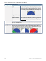
Zoom In
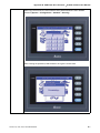
Zoom in to get a close look at the elements on ScrEdit work place. (Refer to Fig. 2.5.8, Fig. 2.5.9)
Fig. 2.5.8 Zoom level = 100% (Before Choosing Zoom In command)
2-38
Revision Apr. 30th, 2007, 2007PDD23000002
Chapter 2 Creating and Editing Screens_ScrEdit Software User Manual
Fig. 2.5.9 Zoom level = 300% (After Choosing Zoom In command)
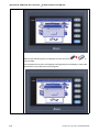
Zoom Out
Zoom out to see more look of the elements on ScrEdit work place. (Refer to Fig. 2.5.10)
Fig. 2.5.10 Zoom level = 50% (After Choosing Zoom Out command)
Revision Apr. 30th, 2007, 2007PDD23000002
2-39
Chapter 2 Creating and Editing Screens_ScrEdit Software User Manual
Actual Size
Return to actual size (100%). This size is relative to the screen size of HMI.
The user can also zoom in or out by clicking icon
2.5.11).
or
or selecting the Zoom level directly (Fig.
Fig. 2.5.11 Zoom level
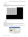
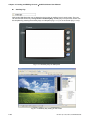
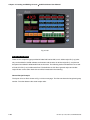
Full Screen
As Fig. 2.5.12. Full screen provides maximum view to edit in ScrEdit. Full screen view will hide all
toolbars and docking windows other than the ScrEdit work place itself. Fig. 2.5.12 full screen also
shows the reference macro command.
Fig. 2.5.12 Full Screen (Pressing Esc key or left-click the mouse can exit Full screen)
2-40
Revision Apr. 30th, 2007, 2007PDD23000002
Chapter 2 Creating and Editing Screens_ScrEdit Software User Manual
I/O Screen
As Fig. 2.5.13. I/O screen also provides maximum view to edit in ScrEdit just like Full screen. But the
difference is that I/O Screen will show the read and write addresses of the element and also shows the
set macro commands.
Fig. 2.5.13 I/O Screen (Pressing Esc key or left-click the mouse can exit Full screen)
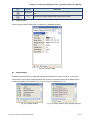
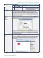
Grid Setup
Grid Setup is a function that can help the user to align and position the element more easily and
precisely. The distance (spacing) between the grid dots can be set by the user freely (Fig. 2.5.14 and
Fig. 2.5.15).
Show Grid: Show the grid dots on the screen.
Snap to Grid: Make the elements snap to grid so that the elements can jump between grid lines when
the user moves them.
Fig. 2.5.14 Gird Settings dialog box
Revision Apr. 30th, 2007, 2007PDD23000002
2-41
Chapter 2 Creating and Editing Screens_ScrEdit Software User Manual
Fig. 2.5.15 Show Gird screen
2-42
Revision Apr. 30th, 2007, 2007PDD23000002
Chapter 2 Creating and Editing Screens_ScrEdit Software User Manual
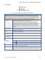
2.6
Menu Bar and Toolbar (Element)
Element
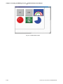
Fig. 2.6.1 Element options
Screen editor provides 14 types of elements and there are many styles for each type. These 14 types
include Button, Meter, Bar, Pipe, Pie, Indicator, Display (data display), Movement (graph display), input,
curve, history (sampling), alarm, graphic and, keypad, etc. The user can select a desired element from the
pull-down menu and drag the size needed on ScrEdit work place (as Fig. 2.6.2 and Fig. 2.6.3).
Fig. 2.6.2 Drag mouse to determine the element size
Revision Apr. 30th, 2007, 2007PDD23000002
2-43
Chapter 2 Creating and Editing Screens_ScrEdit Software User Manual
Fig. 2.6.3 Element display (Create an element)
The user can also right-click the mouse to select the desired element. For the property of each element,
please refer to Chapter 3 for detailed description.
Create an Element
The user can select an element by right-clicking the mouse in work place. Place your mouse pointer in
work place and right-click the mouse to get pull-down menu. Then, the user can select the desired
element and determine the element size by left-clicking the mouse. Later set the property of the
element (Fig. 2.6.4, Fig. 2.6.5, Fig. 2.6.6 and Fig. 2.6.7).
Fig. 2.6.4 Right-click the mouse to select the element
2-44
Revision Apr. 30th, 2007, 2007PDD23000002
Chapter 2 Creating and Editing Screens_ScrEdit Software User Manual
Fig. 2.6.5 Select an element by choosing Element command from menu bar
Fig. 2.6.6 Drag with left mouse button (Left-click the mouse, hold it to drag and release it to finish)
Revision Apr. 30th, 2007, 2007PDD23000002
2-45
Chapter 2 Creating and Editing Screens_ScrEdit Software User Manual
Fig. 2.6.7 Release left mouse button to create an element
Move an Element
The user can use the mouse to move an element. Mouse operation is the same as working in
Windows® operating system. When the mouse cursor changes to a four-arrow icon
, the user can
left-click the mouse and move the element freely (Fig. 2.6.8).
Fig. 2.6.8 Move an Element
2-46
Revision Apr. 30th, 2007, 2007PDD23000002
Chapter 2 Creating and Editing Screens_ScrEdit Software User Manual
Modify Element Width
The user can also use the mouse to modify the width of an element. When the mouse cursor changes
to a two-arrow icon
, the user can left-click the mouse and modify the element width (Fig. 2.6.9).
Fig. 2.6.9Modify Element Width
Modify Element Height
The user can also use the mouse to modify the height of an element. When the mouse cursor changes
to a two-arrow icon , the user can left-click the mouse and modify the element height (Fig. 2.6.10).
Fig. 2.6.10Modify Element Height
Revision Apr. 30th, 2007, 2007PDD23000002
2-47
Chapter 2 Creating and Editing Screens_ScrEdit Software User Manual
Modify Element Width and Height Simultaneously
The user can also use the mouse to modify the width and height of an element simultaneously. When
the mouse cursor changes to a two-arrow icon
or
, the user can left-click the mouse and modify
the element width and height at the same time (Fig. 2.6.11).
Fig. 2.6.11Modify Element Width and Height Simultaneously
Input Characters
The user can input a string of characters that Windows® operating system accepts in the property
table. When the mouse cursor changes to an icon
, the user can start to input any characters that
Windows® operating system accepts where the cursor
blinks (Fig. 2.6.12).
Fig. 2.6.12 Input Characters
2-48
Revision Apr. 30th, 2007, 2007PDD23000002
Chapter 2 Creating and Editing Screens_ScrEdit Software User Manual
Right-click the Mouse
The user can find that different menu will pop up when right-clicking the mouse (Fig. 2.6.13, Fig. 2.6.14
and Fig. 2.6.15).
Fig. 2.6.13 Right-click the mouse on Toolbar - Toolbars window
Fig. 2.6.14 Right-click the mouse in Work Place - Element Selection
Revision Apr. 30th, 2007, 2007PDD23000002
2-49
Chapter 2 Creating and Editing Screens_ScrEdit Software User Manual
Fig. 2.6.15 Right-click the mouse on the element - Editing options (Layout Toolbar)
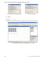
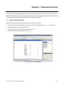
Cross Reference Table
When creating and editing various kinds of elements, what usually happens is that the repeat use of the
same address. In order to avoid this situation, ScrEdit provides the cross reference table function for
the user’s convenience and quick reference. The user can view the read and write addresses of the
selected element and see their relationship or connection with the addresses of other elements, macro
commands or system control area. The user can see how to choose Cross Reference Table
command from menu bar. Fig. 2.6.16 is one simple example to introduce the usage of this function.
The first row of the cross reference table displays the referred element the user selected and the other
rows below the first row displays the elements which have the same write address. The user can
double-click the row and ScrEdit will switch to the corresponding screen of the referred address
automatically. In Fig.2.6.16, ScrEdit switches to the corresponding screen of the referred address
automatically and select the reference element.
Fig. 2.6.16 Cross Reference Table dialog box
2-50
Revision Apr. 30th, 2007, 2007PDD23000002
Chapter 2 Creating and Editing Screens_ScrEdit Software User Manual
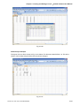
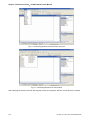
Element Part List
When Element Part List function is enabled, ScrEdit will sort out and classify all the elements on the
current screen. The user can click the tab to switch to the classification that the user wants to view. The
related addresses and corresponding properties will be listed in each classification (Name, Describe,
Write / Read address, Trigger address, Trigger type, Interlock and Level) in each tab (Fig. 2.6.17). The
user can double-click the column to let ScrEdit select the element automatically and allow the user to
edit the detailed property of the selected element in property table.
Fig. 2.6.17 Element Part List dialog box
Revision Apr. 30th, 2007, 2007PDD23000002
2-51
Chapter 2 Creating and Editing Screens_ScrEdit Software User Manual
2.7
Menu Bar and Toolbar (Screen)
Screen
In Screen options, ScrEdit provides some screen editing functions (Fig. 2.7.1). Please refer to the following
sections for more detailed introduction.
Fig. 2.7.1 Screen options
If the user presses the close box, it will hide the current screen without exiting. In Windows, it will exit the
current screen by clicking close box and remind the user to save before exiting. However, in ScrEdit
environment, the current screen will not be deleted and it will not remind the user to save. The function of
clicking the close box only hides the current screen.
New Screen
Create a new screen. The user can choose Screen > New Screen or click the New Screen icon
,
or use keyboard shortcuts by pressing Shift + N to open a new editing screen. The new screen can be
named and numbered by the user. The setting dialog box is shown as Fig. 2.7.2.
Fig. 2.7.2 New Screen dialog box
2-52
Revision Apr. 30th, 2007, 2007PDD23000002
Chapter 2 Creating and Editing Screens_ScrEdit Software User Manual
Open Screen
Open an old screen. The user can choose Screen > Open Screen or click the Open Screen icon
,
or use keyboard shortcuts by pressing Shift + O. When choosing open screen, the user can preview
each screen in Open Screen dialog box (Fig. 2.7.3).
Fig. 2.7.3 Open Screen dialog box
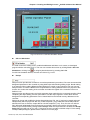
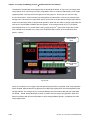
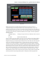
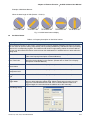
Screen Management
When Screen Management function is enabled (Fig. 2.7.4), the user can duplicate, paste and cut the
screen using the mouse, just like the function of Windows Explorer in Windows® operating system. In
Screen Management dialog box, the user can right click the mouse to manage all of the screens (Fig.
2.7.5). Please note that the user cannot undo the action of cut screen. It is the same as delete screen
that screen will be lost but it can be pasted to get the same screen (Fig. 2.7.6). Besides, right-click the
mouse to select the Edit Save Screen function, and then the user can drag the mouse to determine
the screen saver display (Fig. 2.7.7). For the setting of screen saver, please click Options >
Configuration > Other.
Revision Apr. 30th, 2007, 2007PDD23000002
2-53
Chapter 2 Creating and Editing Screens_ScrEdit Software User Manual
Fig. 2.7.4 Screen Management dialog box
Fig. 2.7.5 Right-click the mouse
2-54
Revision Apr. 30th, 2007, 2007PDD23000002
Chapter 2 Creating and Editing Screens_ScrEdit Software User Manual
Fig. 2.7.6 Warning message after screen is cut
Fig. 2.7.7 Drag the mouse to determine the screen saver display
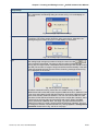
Cut Screen
Cut whole screen to clipboard, just like the Microsoft Office Clipboard function. The difference is that
Microsoft Office Clipboard allows the user to cut text and graphic items and the Cut Screen function
only allows the user to cut a whole screen. The user can execute this function by choosing Screen >
Cut Screen, or use keyboard shortcuts by pressing Shift + T.
Please note that the user cannot undo the action of cut screen. It is the same as delete screen
that screen will be lost but it can be pasted to get the same screen (Fig.2.7.8).
Fig. 2.7.8 Cut Screen message
Revision Apr. 30th, 2007, 2007PDD23000002
2-55
Chapter 2 Creating and Editing Screens_ScrEdit Software User Manual
Copy Screen
Copy whole screen. The user can execute this function by clicking Screen > Copy Screen or use
keyboard shortcuts by pressing Shift + C.
Paste Screen
The user can paste a screen by clicking Screen > Paste Screen or use keyboard shortcuts by pressing
Shift + P. All screen setting will be the same as original screen after pasting but the screen number will
be given automatically by ScrEdit.
Delete Screen
Delete the current editing screen or element. The user can delete a screen by clicking Screen > Delete
Screen or use keyboard shortcuts by pressing Shift + D.
Please note that after executing Delete Screen, the user cannot undo the action of delete screen
(Fig.2.7.9).
Fig. 2.7.9 Delete Screen Message
Export
Export an project to BMP format. The user can execute this function by clicking Screen > Export or
clicking the Export icon
, or use keyboard shortcuts by pressing Shift + E.
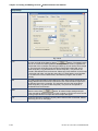
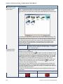
Import
Import a picture to be the background of the editing screen. Please note that this background of the
editing screen is different than the base screen. The nature of an imported picture differs greatly from
that of the base screen. The imported picture cannot exist in ScrEdit as an element. However, the base
screen can be regarded as an element and then exist in the editing screen after a compile operation is
completed (The definition and usage of the base screen will be introduced more in the section of
“Screen Properties”). The file types of available imported picture can be BMP, JPG and GIF, etc. The
user can execute this function by clicking Screen > Import or use keyboard shortcuts by pressing Shift
+ I.
2-56
Revision Apr. 30th, 2007, 2007PDD23000002
Chapter 2 Creating and Editing Screens_ScrEdit Software User Manual
Clear Import Data
The user can free more disk space by clearing the imported data that the user does not want to use.
Execute this function by clicking Screen > Clear Import Data.
Screen Open Macro
When Screen Open Macro function is selected, the Macro will be executed automatically once
opening screen occurs. (Please refer to Chapter 4 for the usage and editing method of Macro.)
Screen Close Macro
When Screen Close Macro function is selected, the Macro will be executed automatically once the
screen is closed. (Please refer to Chapter 4 for the usage and editing method of Macro.)
Screen Cycle Macro
When Screen Cycle Macro function is selected, the Macro will be executed continuously once the
screen is displayed. (Macro will be executed continuously by the cycle time setting) (Please refer to
Chapter 4 for the usage and editing method of Macro.)
The user also can click the Screen Open Macro, Screen Close Macro and Screen Cycle Macro options
from the Property Table to enter intro Screen Open Marco editing environment (Fig. 2.3.10).
Fig. 2.7.10 Screen Open Marco editing environment
Revision Apr. 30th, 2007, 2007PDD23000002
2-57
Chapter 2 Creating and Editing Screens_ScrEdit Software User Manual
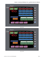
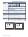
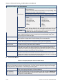
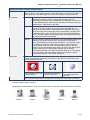
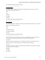
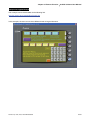
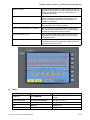
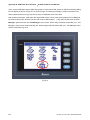
Auxiliary Key
DOP series HMI allows the user to determine the function of auxiliary keys in each screen. The user
can execute this function by clicking Screen > Auxiliary Key. Auxiliary key set up for each screen can
be completed by pressing the auxiliary keys on HMI panel (Fig. 2.7.11) or on the screen (Fig. 2.7.12).
Fig. 2.7.11 Auxiliary Keys on HMI panel
Fig. 2.7.12 Auxiliary Key setting on the screen
2-58
Revision Apr. 30th, 2007, 2007PDD23000002
Chapter 2 Creating and Editing Screens_ScrEdit Software User Manual
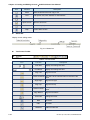
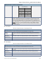
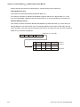
In Table 2.7.1, the user can see how many user-defined auxiliary keys are available for each model.
Table 2.7.1 Available user-defined auxiliary keys
DOP-A/AE/AS Series Model Name
Available User-defined Auxiliary Keys
DOP-AS38BSTD
4
DOP-A (E) 57BSTD
4
DOP-A (E) 57GSTD
4
DOP-A (E) 57CSTD
4
DOP-A75CSTD
6
DOP-AE80THTD
6
DOP-AE94BSTD
11
DOP-A10TCTD
7
DOP-AE10THTD
7
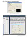
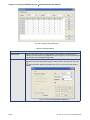
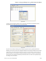
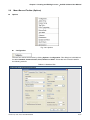
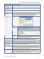
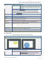
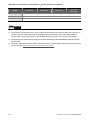
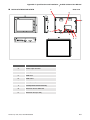
Screen Properties
The user can decide the properties of the current editing screen by clicking Screen > Screen
Properties or choosing Screen Properties from docking windows to set the current screen (Fig.
2.7.13). For the setting of Screen Properties, please refer to Fig. 2.7.14 and Table 2.7.2.
Fig. 2.7.13 Choosing Screen Properties from docking windows
Revision Apr. 30th, 2007, 2007PDD23000002
2-59
Chapter 2 Creating and Editing Screens_ScrEdit Software User Manual
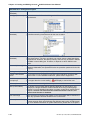
Fig. 2.7.14 Screen Properties dialog box
Table 2.7.2 Screen Properties setting
Function
Screen Number
Screen
Application
Description
The screen number range is within 1~65535 and the number cannot be
repeated.
General View Regarded as general view screen. The element created by the user can be
Screen
downloaded to HMI after compile operation and display on HMI screen.
Apply Print
Screen
1. Regarded as print screen. The printer can print the element created by
the user after a compile operation. This option is only available in DOP
series HMI which supports printer function.
2. When Apply Print Screen function is selected, the editing range will be
scaled to the actual paper size of the printer. The user can only print
the elements within the range of the paper size. This option is usually
used for print typesetting.
The user can find a printer setting by clicking Option > Configuration >
Print shown as Fig. 2.7.15 below.
Fig. 2.7.15 Print tab in Configuration option
2-60
Revision Apr. 30th, 2007, 2007PDD23000002
Chapter 2 Creating and Editing Screens_ScrEdit Software User Manual
Function
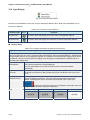
Sub-screen
Setting
Check the
check box next
to “This screen
is a subscreen”
Description
The check box next to “This screen is a sub-screen” can be checked only
when General View Screen option is selected. Therefore, before setting
sub-screen function, please ensure General View Screen option is
selected.
Fig. 2.7.16 Sub-screen setting
Width
It is used to set the width of sub-screen and the unit is Pixel.
Height
It is used to set the height of sub-screen and the unit is Pixel.
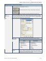
Sub-screen
Position
The user can decide if the sub-screen is shown on the center position of
HMI display or specify the display position freely. Only input the coordinate
value directly (X and Y axis) or press the mouse button
sub-screen to the position the user decided (Fig. 2.7.17).
to drag the
Fig. 2.7.17 Sub-screen position
Title Bar
When the check box next to “Use Title Bar” is checked, the title bar will be
shown when opening sub-screen.
Cycle Macro Delay Time
It is used to set Cycle Macro Delay Time when this screen is executed
every time. The range of the cycle macro delay time is within 100ms ~ 5s.
Fast Refresh Rate
There are three levels of the Fast Refresh Rate and they are High, Medium
and Low. The purpose of this function is used to make some elements be
displayed immediately when switching screens. Please note that this
function is designed to provide fast value refresh speed for the element
which performs communication frequently. Therefore, it only allows four
elements that can be renewed immediately in each screen. If the user uses
this function on too many elements, it may affect the normal speed of HMI
operation. So, we recommend the user not to activate this function if not
necessary.
Revision Apr. 30th, 2007, 2007PDD23000002
2-61
Chapter 2 Creating and Editing Screens_ScrEdit Software User Manual
Function
Hard Copy
Region
Setting
The user can find this function only in DOP series HMI which supports
printer function. If the user wants to enable this function, setting the printer
in advance is necessary. Please go to Option > Configuration > Print
(Fig. 2.7.15) and select the printer first. When this function is enabled, if
one report list button is created and its assigned output device is a printer,
once the user presses the report list button, HMI will refer to the setting in
Hard Copy Region option and execute the screen-printing.
Top-Left
It is used to set the region of HMI printing area (also called Hard Copy
Region) and the unit is Pixel.
Right-Bottom
Base Screen Check the check
box next to
“Need a base
screen”
2-62
Description
Every screen can specify any one of the editing screens as a base screen.
When the check box next to “Need a base screen” is checked, the base
screen will be moved to the back (behind all other elements) as a ground
picture. After compile operation is completed and the screen data is
downloaded to HMI, HMI will execute all of the elements on the base
screen correctly.
Revision Apr. 30th, 2007, 2007PDD23000002
Chapter 2 Creating and Editing Screens_ScrEdit Software User Manual
2.8
Menu Bar and Toolbar (Tools)
Tools
Fig. 2.8.1 Tool options
Compile
It is used to compile editing screen to the format for HMI. During compiling, all of the compiling
messages, including any errors, will be written to output field. When there is any error occurs, system
will remind the user. If there was no error during compiling process, an object file would be produced.
The user can execute this function by clicking Tools > Compile or clicking icon
directly or using
keyboard shortcuts by pressing Ctrl + F7. If this project is a new project, it will remind the user of
saving before compiling. If this project has been saved or it is an old project, it will compile directly.
After compile operation is finished, ScrEdit will save the file again automatically.
Table 2.8.1 Debug Compiling Error
Debug Compiling Error during Compiling Process
1. Create a new project.
2. Create a button element and a numeric entry element on HMI screen and do not change the
element default property as the Fig. 2.8.2 below.
Fig. 2.8.2
Revision Apr. 30th, 2007, 2007PDD23000002
2-63
Chapter 2 Creating and Editing Screens_ScrEdit Software User Manual
Debug Compiling Error during Compiling Process
3. When pressing
icon to execute compile operation, error message dialog box will pop up to warn
the user of compiling error and show how many errors there are. In Fig. 2.8.3, we can see that there
are two errors occurred and they are all displayed in the output window.
Fig. 2.8.3 Compiling errors during compiling process
4. Once error occurs, the correspondent message will display in output window. The user can click the
error message and ScrEdit will switch to error element window automatically.
Download Screen & Recipe
The user can download screen data and recipe to HMI by clicking Tools > Download Screen &
Recipe or clicking
icon directly or using keyboard shortcuts by pressing Ctrl + F8 (Fig. 2.8.4).
If PC cannot connect to HMI, the error messages will be displayed and warn the user (Fig. 2.8.5, Fig.
2.8.6, Fig. 2.8.7 and Fig. 2.8.8). The user can set download interface by clicking Options >
Configuration or by clicking Options > Environment. The download interface can be USB or RS-232.
2-64
Revision Apr. 30th, 2007, 2007PDD23000002
Chapter 2 Creating and Editing Screens_ScrEdit Software User Manual
Fig. 2.8.4 Start to download (the progress will be from 0 to 100%)
Fig. 2.8.5 USB open error message
Fig. 2.8.6 USB disconnect error message
Fig. 2.8.7 Incorrect model name error message
Revision Apr. 30th, 2007, 2007PDD23000002
2-65
Chapter 2 Creating and Editing Screens_ScrEdit Software User Manual
Fig. 2.8.8 Not compile error message
Download Screen
It is only used to download screen data to HMI. The user can execute it by clicking Tools > Download
directly or using keyboard shortcuts by pressing Ctrl + F9.
Screen or clicking icon
The download process is the same as the function of Download Screen & Recipe. The only difference
is that the function of Download Screen & Recipe allows the user to download the screen data and
recipe both but the function of Download Screen allows the user to download screen data only. For the
download screen, please refer to Fig. 2.8.4 above.
On Line Simulation
It is used to simulate DOP series HMI by computer but HMI should also connect to PLC first to drive
PLC by PC simulation through PC communication port. Therefore, the user cannot execute the function
of On Line Simulation without connecting PLC. But the user can execute the function of Off Line
Simulation without connecting PLC. On Line Simulation function can execute by clicking Tools > On
Line Simulation or clicking icon
directly or using keyboard shortcuts by pressing Ctrl + F4.
Before executing On Line Simulation, system will ask the user to set the communication port for
connecting to PLC first (Fig. 2.8.9). For On Line Simulation Screen, the user can refer to Fig. 2.8.10.
Fig. 2.8.9 COM Port Setting
2-66
Revision Apr. 30th, 2007, 2007PDD23000002
Chapter 2 Creating and Editing Screens_ScrEdit Software User Manual
Fig. 2.8.10 On Line / Off Line Simulation Screen
Off Line Simulation
It is used to test if the editing screen, read/write addresses and Macro on is correct on developed
program without connecting to PLC. The user can execute this function by clicking Tools > Off Line
Simulation or clicking icon
or using keyboard shortcuts by pressing Ctrl + F5.
For Off Line Simulation Screen, the user can refer to Fig. 2.8.10.
Recipe
Recipe function provides the controller a convenient parameter input method. The user can transmit the
designated parameter to the controller by using HMI recipe after finishing editing recipe. Bread making
is an example. When making different bread, baking time control is very important. The user can use
Recipe function to meet the different time requirements for making different bread. The purpose of this
function is to reduce the loading of the controller and make the register of the controller to be more
flexible in use.
Recipe function provides an easy and quick parameter input method for the connected controller. When
completing the recipe editing, the user just needs to use the recipe register in control block and the
designated corresponding parameters can be transmitted into the internal memory addresses of the
controller.
Recipe can be set and modified by Recipe Setup dialog box (Fig. 2.8.11) and can be saved and used
independently without project file. Not only 16 bits recipe file (*.rcp), Delta DOP series HMI products
also allow the user to save the recipe data as a 32 bits recipe file (*.csv). Then, the user can edit csv
file in Microsoft Windows@ Excel environment conveniently. Before using recipe, the user should
enable recipe function first by clicking Tools > Recipe. After the recipe function is enabled, the Recipe
Setup dialog box will pop up (Fig. 2.8.11) and then the user can start to edit the recipe. For the setting
of Recipe Setup dialog box, please refer to Table 2.8.2 on next page.
Revision Apr. 30th, 2007, 2007PDD23000002
2-67
Chapter 2 Creating and Editing Screens_ScrEdit Software User Manual
Fig. 2.8.11 Recipe Setup dialog box
Table 2.8.2 Recipe Editing
Recipe Setup
Enable Recipe
When the check box next to “Enable Recipe” is checked, the recipe function is
enabled. If the user does not enable this function, the user can not do this function
even the user has downloaded recipe data.
Address
The user can input the starting address of recipe data here. It can accept the
address in PLC input format and internal memory format. The user also can click
button to get the address input dialog box (Fig. 2.8.12) to input the starting
address. Fig. 2.8.12 Input starting address dialog box
2-68
Revision Apr. 30th, 2007, 2007PDD23000002
Chapter 2 Creating and Editing Screens_ScrEdit Software User Manual
Recipe Setup
Length
It is used to set the recipe length. The unit is Word and it should be set to more
than 0. Otherwise, the following dialog box shown as Fig. 2.8.13 will display on
the screen.
Fig. 2.8.13 Length input error message
Group
It is used to set group number of recipe. It is convenient for the user to use recipe
by switching. The group number should be set to more than 0. Otherwise, the
following dialog box shown as Fig. 2.8.14 will display on the screen.
Fig. 2.8.14 Group input error message
Input
After setting length and group number of recipe, the user can click
button to edit the recipe data. The memory size for recipe is limited and the
memory size for recipe is 64K. It indicates that the total recipe size should be less
than 64K (The number of Length x Groups should be less than 65536). If the total
recipe size exceeds the limit, the user will see a warning message shown as Fig.
2.8.15 displayed on the screen.
Fig. 2.8.15 Input error message
The above-mentioned memory means the non-volatile memory of HMI, i.e.
SRAM. Some DOP series HMI, which supports USB host function, allows the user
to use more recipe data via this USB host interface. Supporting USB host function
means it has a built-in USB host interface. The user can connect HMI to a USB
flash drive via this USB host interface and input more recipe data. However, there
is still a limit for the input value of recipe length and groups. When Hold Data
Place is selected as USB flash drive, the length x groups should be less than
4096K (The number of Length x Groups should be less than 4194304). The user
can change the selection of Hold Data Place by clicking Options > Configuration
> Standard. Please refer to Fig. 2.8.16 on next page.
Revision Apr. 30th, 2007, 2007PDD23000002
2-69
Chapter 2 Creating and Editing Screens_ScrEdit Software User Manual
Recipe Setup
Input
Fig. 2.8.16
Open
Save
Reset
Clear
2-70
The user can load recipe data by clicking
button. The loaded recipe
data do not contain the starting address of recipe data. Therefore, regardless of
which brand of the controller connecting to HMI, they all can use the same recipe
file. There are two recipe file types provided in Delta DOP series HMI, one is
16bits recipe file (*.rcp) and the other is 32 bits recipe file (*.csv) that can be
opened in Windows® Excel environment. Please pay close attention to the format
of recipe file and make sure that the recipe file is a 16 bits data or a 32 bits data.
Do not select the incorrect data format; otherwise the program will not work
normally.
It is used to save the editing recipe data to be a file. When saving recipe file, the
starting address will not be saved. This lets the user uses the same recipe file in
the different brand of the controller. The user also can save the recipe file as
16bits recipe file (*.rcp) and 32 bits recipe file (*.csv) that can be opened in
Windows® Excel environment.
When the user clicks
button, all related recipe setting and input
recipe data will be deleted. There is no other method to retrieve the recipe except
for using Import function to import the saved recipe data again.
All input recipe will be cleared to 0 (zero) when clear function is selected. Please
refer to Fig. 2.8.17 on next page.
Revision Apr. 30th, 2007, 2007PDD23000002
Chapter 2 Creating and Editing Screens_ScrEdit Software User Manual
Recipe Setup
Clear
Fig. 2.8.17
Print
OK
It will print all recipe data on current screen.
After inputting the recipe data, the user can click
button to save the
recipe data for transmitting or modifying. At the same time, ScrEdit will check the
validity of all input recipe data. If there is invalid input recipe data value, the OK
function will not be executed successfully. For example, in Fig. 2.8.18, ScrEdit
found an error and a warning message dialog box display on the screen as the
user did not input the starting address of the recipe.
Fig. 2.8.18
Cancel
It will force the system to exit the Recipe Setup dialog box without saving anything
after clicking
clicking this button.
button. Therefore, please consider carefully before
32 bits Floating Recipe
32 bits Floating Recipe function provides the user to save 32 bits data. The data format includes
Signed Decimal, Unsigned Decimal and Floating (The total of Integral and fractional digits cannot
exceed 7 digits). To enable this function, the user can click Tools > 32 bits Floating Recipe. For the
setting of Recipe Setup dialog box, please refer to Fig. 2.8.19 and Table 2.8.3 on next page.
Revision Apr. 30th, 2007, 2007PDD23000002
2-71
Chapter 2 Creating and Editing Screens_ScrEdit Software User Manual
Fig. 2.8.19 32 bits Floating Recipe Setup dialog box
Table 2.8.3 32 bits Floating Recipe Editing
32 bits Floating Recipe Setup
New: Create a new 32 bits floating recipe file
Press
to create a new 32 bits floating recipe. After clicking
, a 32 bits
floating recipe setup dialog box will display and the user can use it to set the
settings of a 32 bits floating recipe. The user can determine the recipe storage
address, the length and group number of the recipe, the memory format, and the
integer & fractional digit number of the recipe data. There are three kinds of
memory format provided, including Unsigned Decimal, Signed Decimal and
Floating (Fig. 2.8.20, Fig. 2.8.21 and Fig. 2.8.22). Integer and fractional digit
number cannot be selected when the memory format is set to Unsigned Decimal
and Signed Decimal. These two options is only available when the memory format
is set to Floating. But the total of the Integer and fractional digit number cannot
exceed 7 digits. For the number of the 32 bits floating recipe, up to 255 recipes
can be set in a 32 bits floating recipe file.
Fig. 2.8.20
2-72
Fig. 2.8.21
Revision Apr. 30th, 2007, 2007PDD23000002
Chapter 2 Creating and Editing Screens_ScrEdit Software User Manual
32 bits Floating Recipe Setup
Fig. 2.8.22
Open: Open a 32 bits floating recipe file
Press
to open a 32 bits floating recipe file. The file format can be Recipe 32
bits File (*.rcp) and Excel CSV File (*.csv) (Fig. 2.8.23). Please pay close attention
to the format of recipe file and make sure that the recipe file is a 16 bits data or a
32 bits data. Do not select the incorrect data format; otherwise the program will
not work normally.
Fig. 2.8.23
Revision Apr. 30th, 2007, 2007PDD23000002
2-73
Chapter 2 Creating and Editing Screens_ScrEdit Software User Manual
32 bits Floating Recipe Setup
Save: Save a 32 bits floating recipe file
Press
to save a 32 bits floating recipe file. The default file format of a 32 bits
floating recipe file is Excel CSV file (*.csv) (Fig. 2.8.24).
Fig. 2.8.24
Delete: Delete a 32 bits floating recipe
Press
to delete unnecessary 32 bits floating recipe.
Recipe Storage Address :
Display the storage address of a 32 bits floating recipe.
Setup: 32 bits floating recipe setup
When clicking
, a 32 bits floating recipe setup dialog box will display and the
user can use it to change the settings of a 32 bits floating recipe.
Enable: Enable 32 bits floating recipe function
This function should be selected when the user wants to use 32 bits floating
recipe function.
Download Recipe
Downloads recipe to HMI. It can save time when the user wants to download recipe date only. What the
user needs to do is to click Tools > Download Recipe and then the recipe data can be downloaded to
HMI. The general extension name of recipe file is rcp (Fig. 2.8.25).
2-74
Revision Apr. 30th, 2007, 2007PDD23000002
Chapter 2 Creating and Editing Screens_ScrEdit Software User Manual
Fig. 2.8.25 Download Recipe
Recipe Example
For recipe control, the user needs to use Recipe Control Register (RECR) and Designated Recipe
Group Number Register (RBIR) to control the read and write operation of recipe. The following
section only describes part of the introduction of recipe function. Please refer to Chapter 5 of Delta HMI
user manual for more detailed description of the control block.
This recipe example can be downloaded via the following link:
http://59.120.64.39:81/phpbb2/files/recipe_202.dop
The function and explanation of each WORD (register) of control block are listed below.
Word Number
Register Number
Example
0
Register for designating Screen Number (SNIR)
Dn
(D0)
1
Control Flag Register (CFR)
Dn+1
(D1)
2
Curve Control Register (CUCR)
Dn+2
(D2)
3
Register for Sampling History Buffer (HBSR)
Dn+3
(D3)
4
Register for Clearing History Buffer (HBCR)
Dn+4
(D4)
5
Recipe Control Register (RECR)
Dn+5
(D5)
6
Register for designating Recipe Group Number (RBIR)
Dn+6
(D6)
7
System Control Flag Register (SCFR)
Dn+7
(D7)
Revision Apr. 30th, 2007, 2007PDD23000002
2-75
Chapter 2 Creating and Editing Screens_ScrEdit Software User Manual
Recipe Control Register (RECR)
Bit Number
Function
0
Recipe number change
1
Read recipe (PLC ൺ HMI)
2
Write recipe (HMI ൺ PLC)
3
Recipe group number change
4~7
Reserved
8~15
Designate change recipe group number
Control Flag for Changing Recipe Number
There are two kinds of methods for changing and calling recipe number. One method is to use HMI
internal register, RCPNO directly. RCPNO is the internal system register used for designating recipe
number. The other method is to use Recipe Control Register (RECR) (Dn+5). When the user wants to
change HMI recipe number, i.e. RCPNO value through control block settings, first, it needs to write
recipe number (N) into Designated Recipe Number Register (RBIR) (Dn+6, please refer to the
explanation of Register for Designating Recipe Number (RBIR) in Chapter 5) and use this control flag
to trigger Bit 0 of Dn+5 to be ON. After setting, RCPNO will be changed to N automatically. This flag
needs be set to OFF and then ON if the user wants to trigger again.
Control Flag for Reading Recipe
The user can change the recipe value of PLC by triggering this control flag (Bit 1 is set to ON). Before
reading a recipe from PLC, the user should designate the recipe number (N) first (Please refer to the
section “Control Flag for Changing Recipe Number” in Chapter 5). Then, trigger this control flag to ON
(Bit 1 is set to ON). After setting, the recipe will be read from PLC and stored in designating area of
HMI. This flag needs be set to OFF and then ON if the user wants to trigger again.
Control Flag for Writing Recipe
Before writing a recipe to PLC, the user should designate the recipe number (N) first (Please refer to
the section “Control Flag for Changing Recipe Number” in Chapter 5). Then, trigger this control flag to
ON (Bit 2 is set to ON). After setting, the recipe will be written to PLC. This flag needs be set to OFF
and then ON if the user wants to trigger again.
Control Flag for Changing Recipe Group Number
There are two kinds of methods for changing and calling recipe group number. One method is to use
HMI internal register, RCPG directly. RCPG is the internal system register used for designating recipe
group number. The other method is to use Recipe Control Register (RECR) (Dn+5). When the user
wants to change HMI recipe group number through control block settings, first, it needs to write recipe
2-76
Revision Apr. 30th, 2007, 2007PDD23000002
Chapter 2 Creating and Editing Screens_ScrEdit Software User Manual
group number (N) into the high byte of this control block and use this control flag to trigger, Dn+5 (Bit 3
is set to ON). After setting, RCPG will be changed to N automatically. This flag needs be set to OFF
and then ON if the user wants to trigger again.
Register for Designating Recipe Number (RBIR)
Word
0
Function
Designate receipt number which the user wants to change
By writing recipe group number (N) into Designated Recipe Number Register (RBIR), RCPNO value
can be changed. The user can use the control flag for changing recipe number of Recipe Control
Register (RECR) to write recipe group number (N) into Designated Recipe Number Register (RBIR)
and change RCPNO value.
The following section will introduce how to use recipe. The example is named as recipe.dop and it is
saved in the Example folder under Screen Editor software installation directory.
Please click Tools > Recipe on menu bar and enter into Recipe Setup dialog box. In this example, the
Length is set to 6, Group is set to 7 and Address is set to Internal Memory $220. After complete the
above settings, your Screen will look like the Fig. 2.8.26 shown below.
Fig. 2.8.26 Recipe Setup dialog box
Revision Apr. 30th, 2007, 2007PDD23000002
2-77
Chapter 2 Creating and Editing Screens_ScrEdit Software User Manual
Besides, in order to perform simulation operation more conveniently, the Address of Control Block is set to
Internal Memory $0. Your Screen will look like the Fig. 2.8.27 shown below.
Fig. 2.8.27 Control Block Settings of Configuration dialog box
2-78
Revision Apr. 30th, 2007, 2007PDD23000002
Chapter 2 Creating and Editing Screens_ScrEdit Software User Manual
Fig. 2.8.28 Recipe Example
When the user select “Enable Recipe” option in Recipe Setup dialog box, there are RCP and RCPNO
two kinds of device types available for the user to select in Input dialog box (See the following Fig.
2.8.29). RCPNO is used to change the recipe group and RCP is used to store the recipe data. The
content of recipe register depends on the recipe data set by the user. The recipe changes, the recipe
register also changes. In this example, RCP0 ~ RCP17 are recipe registers and HMI will store the
recipe data set by the user in these recipe registers. If these registers have the corresponding recipe
set by the user, HMI will create recipe data into the internal recipe register automatically and select the
value in Input dialog box (See the following Fig. 2.8.29). $220 ~ $225 are the destination addresses
that are used to store the recipe data (Generally, the recipe data are set to be stored in the addresses
of external controller registers, but for the convenience of simulation operation, we set the recipe
storage address in the internal memory). $5 is used to display the status of Recipe Control Register
(RECR). Write Recipe ($5.2) button is used to execute write recipe operation. When this button is
pressed, HMI will write the recipe data from HMI recipe register RCP into the designated recipe storage
address ($220 ~ $225). Read Recipe ($5.1) button is used to execute read recipe operation. When this
button is pressed, HMI will read recipe data of recipe storage address ($220 ~ $225) back to HMI
recipe register RCP. $6 is RBIR, i.e. Designated Recipe Group Number Register and its function is the
same as the function of RCPNO. The difference between these two registers is that RCPNO is a fixed
address of HMI internal memory, but the address of RBIR can be changed according to the setting of
control block (See 2.8.27 on previous page).
Revision Apr. 30th, 2007, 2007PDD23000002
2-79
Chapter 2 Creating and Editing Screens_ScrEdit Software User Manual
Fig. 2.8.29 Input dialog box
The definition of Delta HMI recipe register RCP is described as follows. In Fig. 2.8.26, the length of example
recipe is set to 6 and the group of example recipe is set to 7. However, HMI actually create recipe registers
(RCP0 ~ RCP15) which the length is 6 but the group is 8. As the user can see in the Fig. 2.8.30, RCP0 ~
RCP5 is defined as recipe buffer area and RCP6 ~ RCP17 is the actual recipe storage area. The function of
recipe buffer area is for the user to put the desired change recipe data no matter execute Write Recipe or
Read Recipe operation. When the user want to change recipe data, the user have to use RCPNO or RBIR
these two registers. In the example shown in Fig. 2.8.30, when RCPNO is set to 2, it means that the using
recipe group is 2nd group. At this time, HMI will move the data of 2nd group and put them in the recipe buffer
area (RCP0 ~ RCP5). Besides using internal memory address (RCPG and RCPNO), the user also can enter
into Configuration dialog box and change the address value of recipe register directly. Since the example
control block address is set to $0, the user should use $6 RBIR, i.e. Designated Recipe Group Number
Register to designate recipe group and press Change Group ($5.0) button to designate the desired using
recipe group. When Write Recipe ($5.2) button is pressed, Write Recipe operation will be enabled. HMI will
write the recipe data from HMI recipe register RCP into the designated recipe storage address ($220 ~
$225). The example in Fig. 2.8.30 just displays the screen when HMI write the recipe data into $220 ~ $225.
Read Recipe ($5.1) button is used to execute read recipe operation. When this button is pressed, HMI will
read recipe data of recipe storage address ($220 ~ $225) back to HMI recipe register RCP.
2-80
Revision Apr. 30th, 2007, 2007PDD23000002
Chapter 2 Creating and Editing Screens_ScrEdit Software User Manual
Recipe Buffer Area
Recipe Storage
Area
Fig. 2.8.30 Change recipe group
32 bits Recipe Example
This 32 bits recipe example can be downloaded via the following link:
http://59.120.64.39:81/phpbb2/files/32bit_recipe.dop
For the convenience of the user and enhance the flexibility of Delta HMI product on application, not
only the existing recipe function, the advanced 32 bits recipe function is also provided. The user can
manage the recipe data more flexibly and use this function on high precision controller and industry, e.g.
CNC controller, etc.
Besides inputting 32 bits recipe data, the 32 bits floating recipe function also allows the user to save
Double Word value. But the best advantage is that it makes recipe editing to be easier and more
flexible. The existing recipe function is a two-dimensional matrix. It means the user can set one recipe
length and one recipe group to create one recipe data in a project only. It is not user-friendly when the
user wants to create one more recipe data in the same project. Therefore, we develop 32 bits floating
recipe function and it is designed for the user that needs to input two and more recipe data in a project
simultaneously. In other word, the 32 bits recipe function can become a three-dimensional matrix. So,
the settings of the 32 bits recipe function will be a little different that the existing recipe function.
Revision Apr. 30th, 2007, 2007PDD23000002
2-81
Chapter 2 Creating and Editing Screens_ScrEdit Software User Manual
For recipe control, the user needs to use Recipe Control Register (RECR) and Designated Recipe
Group Number Register (RBIR) to control the read and write operation of recipe. The user can refer
to page 2-74 ~ page 2-79 for the introduction and example of recipe function. For more detailed
description of the control block, please refer to for Chapter 5 of Delta HMI user manual
The following section will introduce how to use 32 bits recipe function. The example is named as 32 bits
recipe.dop and it is saved in the Example folder under Screen Editor software installation directory.
Please click Tools > 32 bits Floating Recipe on menu bar and enter into 32 bits Recipe Setup dialog
box. In this example, you can see that two recipe data is set in different tab. One is B1-4x3 and the
other is B2-5x4. B1-4x3 indicates that its Length is set to 4 and its Group is set to 3. B2-5x4 indicates
that its Length is set to 5 and its Group is set to 4. The memory format of B1 recipe data is set to
Floating and the memory format of B2 recipe data is set to Unsigned Decimal. Please refer to Fig.
2.8.31 below and Fig. 2.8.32 shown on next page.
Fig. 2.8.31
2-82
Revision Apr. 30th, 2007, 2007PDD23000002
Chapter 2 Creating and Editing Screens_ScrEdit Software User Manual
Fig. 2.8.32
In order to perform simulation operation more conveniently, the Address of Control Block is set to
Internal Memory $0. Please refer to Fig. 2.8.33 shown below.
Fig. 2.8.33
Fig. 2.8.34 is an example of starting screen. Besides using internal memory address (RCPG and
RCPNO), the user also can enter into Configuration dialog box and change the address value of recipe
register directly. No matter what kind of method is chosen, the user still needs to execute recipe read
and write operation via Control Block. Pressing Internal Memory button is to switch the recipe data by
using internal memory address and pressing Control Block button is to switch the recipe data through
the settings of the Control Block.
Revision Apr. 30th, 2007, 2007PDD23000002
2-83
Chapter 2 Creating and Editing Screens_ScrEdit Software User Manual
Fig. 2.8.34
When Internal Memory button is pressed, HMI will enter intro the screen shown as Fig. 2.8.35. RCPG is
used to store the recipe data, RCPNO is used to change the recipe group and RCP0 ~ RCP15 are
recipe registers and HMI will store the recipe data set by the user in these recipe registers. $1000 ~
$1006 are the destination addresses that are used to store the recipe data (Generally, the recipe data
are set to be stored in the addresses of external controller registers, but for the convenience of
simulation operation, we set the recipe storage address in the internal memory). Because this example
uses 32 bits recipe data, each recipe data will occupy two WORD registers. It means that the recipe
storage addresses will be $1000, $1002, $1004 and $1006. $5 in green is used to display the status of
Recipe Control Register (RECR). Recipe Write ($5.2) button is used to execute recipe write operation.
When this button is pressed, HMI will write the recipe data from HMI recipe register RCP into the
designated recipe storage address ($1000 ~ $1006). Recipe Read ($5.1) button is used to execute
recipe read operation. When this button is pressed, HMI will read recipe data of recipe storage address
($1000 ~ $1006) back to HMI recipe register RCP. Main button is used to return to the screen shown
as Fig. 2.8.34.
When the value of RCPG is equal to 0, it means that the display data of RCP register is a 16 bits recipe
data. Since there is no 16 bits recipe data set in this example, the value of RCPG will display 0 only
and the display of HMI will be shown as Fig. 2.8.35 on next page. When the value of RCPG is equal to
1, it means that the RCP register will display the B1 recipe data (Fig. 2.8.31) and the display of HMI
screen will be shown as Fig. 2.8.36 on next page.
2-84
Revision Apr. 30th, 2007, 2007PDD23000002
Chapter 2 Creating and Editing Screens_ScrEdit Software User Manual
Fig. 2.8.35
Fig. 2.8.36
Revision Apr. 30th, 2007, 2007PDD23000002
2-85
Chapter 2 Creating and Editing Screens_ScrEdit Software User Manual
The definition of Delta HMI recipe register RCP is described as follows. In Fig. 2.8.31, the length of B1
recipe data is set to 4 and the group of B1 recipe data is set to 3. However, HMI actually create recipe
registers (RCP0 ~ RCP15) which the length is 4 but the group is 4. As the user can see in the Fig.
2.8.37 below, RCP0 ~ RCP3 is defined as recipe buffer area and RCP4 ~ RCP15 is the actual recipe
storage area. The function of recipe buffer area is for the user to put the desired change recipe data no
matter execute Recipe Write or Recipe Read operation. When the user want to change recipe data, the
user have to use RCPNO or RBIR these two registers. In the example shown in Fig. 2.8.37 below,
when RCPNO is set to 2, it means that the using recipe group is 2nd group of B1 recipe data. At this
time, HMI will move the data of 2nd group of B1 recipe data and put them in the recipe buffer area
(RCP0 ~ RCP3).
Recipe Buffer
Area
Recipe Storage
Area
Fig. 2.8.37
As Fig. 2.8.38 shown on next page, when Recipe Write ($5.2) button is pressed, write recipe operation
will be enabled. HMI will write the recipe data from HMI recipe register RCP into the designated recipe
storage address. The example in Fig. 2.8.38 just displays the screen when HMI write the recipe data
into $1000 ~ $1006. Recipe Read ($5.1) button is used to execute recipe read operation. When this
button is pressed, HMI will read recipe data of recipe storage address ($1000 ~ $1006) back to HMI
recipe register RCP.
2-86
Revision Apr. 30th, 2007, 2007PDD23000002
Chapter 2 Creating and Editing Screens_ScrEdit Software User Manual
Fig. 2.8.38
Besides using internal memory address (RCPG and RCPNO), the user also can enter into
Configuration dialog box and change the address value of recipe register directly. In Fig. 2.8.34,
pressing Control Block button is to switch the recipe data through the settings of the Control Block and
the example display will be shown as Fig, 2.8.39. In Fig. 2.8.39, $500 is used to set the desired change
recipe group number. But there is a After Execute Macro set in this register. The macro explanation is
described as follows:
SWAP($501, $500, 1)
Exchange the high and low byte of $500 and store the result in
$501
$5 = $501
Move the value of $501 to $5
Since the example control block address is set to $0, $5 is set to the Recipe Control Register (RECR )
and bit 8 ~bit 15 is defined and used for setting recipe group number. There, the user should set the
designated recipe group, exchange the high and low byte and move the value to $5. After recipe group
number is set, press Block Change ($5.3) button to change recipe group. After the recipe group is
changed, the user should use $6 RBIR, i.e. Designated Recipe Group Number Register to designate
recipe group and press Change Group ($5.0) button to designate the desired using recipe group. When
Recipe Write ($5.2) button is pressed, recipe write operation will be enabled. HMI will write the recipe
data from HMI recipe register RCP into the designated recipe storage address ($1000 ~ $1006). The
example in Fig. 2.8.39 just displays the screen when HMI write the recipe data into $1000 ~ $1006.
Recipe Read ($5.1) button is used to execute read recipe operation. When this button is pressed, HMI
will read recipe data of recipe storage address ($1000 ~ $1006) back to HMI recipe register RCP
Revision Apr. 30th, 2007, 2007PDD23000002
2-87
Chapter 2 Creating and Editing Screens_ScrEdit Software User Manual
Fig. 2.8.39
Recipe CSV File Editing
There are two recipe file types provided in Delta DOP series HMI, one is 16bits recipe file (*.rcp) that
only can be edited in ScrEdit software environment and the other is 32 bits recipe file (*.csv) that can
be opened and edited in Windows® Excel environment. The following section will describe how to edit
a Excel CSV File (*.csv) in Microsoft Excel. The definition of CSV file of general recipe and 32 bits
recipe file are not the same. Both of them will be introduced in the following.
General Recipe Example
The layout of its csv file is shown as Fig. 2.8.40 on next page. The first row shows the length and group
number. The other data are the actual recipe value.
2-88
Revision Apr. 30th, 2007, 2007PDD23000002
Chapter 2 Creating and Editing Screens_ScrEdit Software User Manual
Fig. 2.8.40
32 bits Recipe Example
The layout of its csv file is shown as Fig. 2.8.41 below. The first row shows RCP32-1.0. This is the
version of this 32 bits recipe and the user should not change it.
Fig. 2.8.41
Revision Apr. 30th, 2007, 2007PDD23000002
2-89
Chapter 2 Creating and Editing Screens_ScrEdit Software User Manual
Fig. 2.8.42
Please see Fig. 2.8.42. The right side is the recipe editing window in ScrEdit and the left side is the
Excel editing window. You can see the data within the red frame is the first recipe data. The second
row of the data listed in Microsoft Excel represents the setting values of the 32 bits recipe.
For the connection between the column in Microsoft Excel and the settings of recipe group data, please
refer to the following table.
Column
32 bits Recipe Setup
A
Length
B
Group
C
Integer Number (only can be set when memory format is set to Floating)
D
Fractional Number (only can be set when memory format is set to Floating)
E
Memory Format:
2: Signed Decimal
3: Unsigned Decimal
6: Floating
The data after one empty row is the settings of next 32 bits recipe. The setting method is the same as
the first 32 bits recipe.
2-90
Revision Apr. 30th, 2007, 2007PDD23000002
Chapter 2 Creating and Editing Screens_ScrEdit Software User Manual
2.9
Menu Bar and Toolbar (Options)
Options
Fig. 2.9.1 Options
Configuration
The user can execute this function by clicking Options > Configuration. This dialog box is divided into
five tabs: Standard, Communication, Print, Default and Other. These tabs are covered in detail in
the following sections.
Table 2.9.1 Standard Tab
Standard tab in Configuration option
Revision Apr. 30th, 2007, 2007PDD23000002
2-91
Chapter 2 Creating and Editing Screens_ScrEdit Software User Manual
Standard tab in Configuration option
Application Name
(Standard)
It is also File Name.
HMI Type (Standard)
It is used to select DOP series HMI type for different functions and
requirements.
Base Port Controller
(Standard)
It is used to set connecting external controller: Screen Editor provides various
controllers sorted by manufacturers for the user to select.
Hold Data Place
(Standard)
The backup memory data can be saved in SRAM, SMC and USB flash drive
these three places. The user can select one of them from the Hold Data Place
drop-down list. However, the backup memory data can only be saved in SRAM
and SMC in some HMI types. Therefore, it depends on which HMI the user
select.
Password (Security)
It is used to set the highest priority password. There are 8 levels for the
password. Meanwhile, this password is also the protection password for the file
(project).
Starting Level (Security) It is used to set start-up priority. The highest level is 7 and the lowest level is 0.
Enable USB updating
check
This function is only provided in some DOP series HMI which supports USB
Host function. For the detailed introduction, please refer to Appendix C.
Insufficient password
level prompt
When this check box is checked, if the priority for the element that is not equal
to or higher than the current setting,
will display to remind the user.
Address (Control Block) It is used to set the starting address of system control block.
Size (Control Block)
The length of control block will be different depending on the function. (For
example, the length should be at least 8 Words when using multi-language
function). For more detailed information of system control block, please refer to
Chapter 5. Please note that when the control block size is set to 0, the
control block function is disabled.
Auto reset flags
If this check box is checked, the register in the control block will be cleared to 0
when any operation has been finished in the control block.
Address (Status Block)
It is used to set the starting address of system status block. The length is
constant 8 words. Each word indicates the different status value of HMI system.
For more detailed information of system status block, please refer to Chapter 5.
2-92
Revision Apr. 30th, 2007, 2007PDD23000002
Chapter 2 Creating and Editing Screens_ScrEdit Software User Manual
Standard tab in Configuration option
Optimize Type
Dynamic
When communicating with the controller, read the address
value and optimize the elements that show on the current
screen and adjust the read data length according to the
number of screen elements. It can save the communication
time between HMI and the controller efficiently. We
recommend the user to use this function if there is no special
requirement.
Please note that this Dynamic Optimize function is enabled by
the Optimize option in Communication tab. If the Optimize
option in Communication tab is not selected, even the user
chooses this function in Standard tab, system will not activate
the Dynamic Optimize function.
Static
When communicating with the controller, read the address
value and optimize the elements that show on the current
screen but will not adjust the read data length according to
the number of screen elements.
Please note that this Static Optimize function is enabled by
the Optimize option in Communication tab. If the Optimize
option in Communication tab is not selected, even the user
chooses this function in Standard tab, system will not activate
the Static Optimize function.
Upload / Download
The user can select USB or PC communication port (i.e. RS-232) to upload and
download.
Startup Delay Time
It is used to set the delay time for the startup of the external controller (i.e.
PLC). PLC. The range is 0 ~ 255 seconds.
Clock Macro Delay
It is used to set interval time when executing clock macro every time. The range
is 100 ~ 65535ms.
Table 2.9.2 Communication Tab
Communication tab in Configuration option
Revision Apr. 30th, 2007, 2007PDD23000002
2-93
Chapter 2 Creating and Editing Screens_ScrEdit Software User Manual
Communication tab in Configuration option
Insert / Delete
Controller
Connection
Insert
Press Insert button to determine the connecting device name and
the controller:
It is used to set the connecting controller. Available connecting
controller will be different depending on HMI type the user uses.
(DOP AE and AS series HMI can support three max. different
controllers simultaneously.)
Controller Settings
Delete
It is used to delete the existed connecting controller (One project
needs to connect at least one controller).
Update
Modify the connecting controller or change the controller name.
COM Port
It is used to set the COM port used to communicate with HMI
(COM1 or COM2). COM3 port is only provided in some types of
HMI, e.g. DOP AE and AS series.
Password
Entering a password is necessary for some connecting controllers
before communication.
Comm. Delay
Time
It is used to set a delay time for the startup of an external
controller (i.e. PLC). The range is within 0 ~ 255 ms.
Timeout
It is used to set communication time out time when communicating
with the external controller. The range is within 100 ~ 65535ms.
Retry Count
HMI will try to send communication command to the external
controller repeatedly if the external controller does not respond
during communication. This option is used to set the number of
retry count times. A communication error dialog box will not
appear unless the number of retry count times is reached. The
range is within 0 ~ 255 times.
Optimize
Use this option to enable optimization function. If optimization
function is enabled, all read addresses of all related elements will
be optimized.
Size Limit
This function is available only when “Static” in “Optimize Type”
option on Standard tab is selected. It is used to avoid the screen
updating speed from slowing down when reading a long
continuous address.
When the check box next to “Communication Interrupt times then cancel connected”
is checked, HMI will stop communicating with the external controllers after the
communication interrupt times are reached. The purpose of this function is to avoid a
communication error dialog box will show on the HMI screen when a communication
error occurs after HMI has retried. The range is within 1 ~ 255 times. If the user
wants to recover the communication between HMI and controller again when HMI
stop communicating with the external controllers after the communication interrupt
times are reached, the user can use Bit 0 of the control block D1 (suppose that the
stating address is D0) to control HMI communication. When Bit 1 is set to ON, it will
disable HMI communication. When Bit 1 is set to OFF, it will enable HMI
communication. Please refer to Chapter 5 for more description.
2-94
HMI Station
It is used to set HMI station number. The range is within 0 ~ 255.
PLC Station
It is used to set PLC station number. If PLC does not set station
number, it will use this default setting. The range is within 0 ~ 255.
Revision Apr. 30th, 2007, 2007PDD23000002
Chapter 2 Creating and Editing Screens_ScrEdit Software User Manual
Communication tab in Configuration option
Interface
It is used to set communication interface. There are RS232,
RS422 and RS485 three options. The default setting will be
different depending on HMI type the user uses.
Data Bits
There are 7 Bits and 8 Bits two options.
Stop Bits
There are 1 Bits and 2 Bits two options.
Baud Rate
Communication baud rate. There are 4800, 9600, 19200, 38400,
57600 and 115200 these options. The user can enter the setting
value directly but the max. setting value can not exceed 187500.
Parity
There are None, Odd and Even three options.
Table 2.9.3 Print Tab
Print tab in Configuration option
HMI provides two print options, one is Hard Copy function, which can print the current screen and print
one page one time. The other is Print Typesetting function. If Print Typesetting function is selected, no
only the screen data but also all history data can be output to the printer directly. For more description of
print setting method, please refer to the introduction of Print Typesetting function on page 2-109.
Standard
Margin
Printer
Use this option to set the connecting printer. The user can use the
drop-down list to specify the printer. The printers in the list are sorted
by manufacturers and the user can find the printer easily.
Paper
The user can use the Paper drop-down list to select the paper size.
The predefined paper sizes in the list are A4 and Letter only.
Quality
Only 72DPI option is provided.
The user can determine the blank space (margins) that will not be printed by using
this option. This option can specify the top, bottom, left and right margins and the
unit is mm.
Revision Apr. 30th, 2007, 2007PDD23000002
2-95
Chapter 2 Creating and Editing Screens_ScrEdit Software User Manual
Interface
It is used to set printer interface. The user can specify the communication port of the
printer. There are Parallel Port and USB two options. If Parallel Port is selected, the
optional printer module, DOP-EXPM110 is needed.
Auto Next Page
When the “Auto Next Page” option is selected, the printer will print the next page
automatically. If the checkbox next to “Auto Next Page” is not checked, the printer
will print continuously without breaking for different pages.
Direction
It is used to set printing direction (orientation). There are Vertical (Portrait) and
Horizontal (Landscape) two options.
Table 2.9.4 Default Tab
Default tab in Configuration option
System Default
Value
Start up Screen
Use this option to set the first display screen when HMI is
powered on and started up.
Default Format
When creating elements, it is used to set the default value
format.
Default Screen
When a new editing screen is created, the user can use this
option to set the default screen background color.
System Error Display Use this option to set the display time of system error
Time
message dialog box. The range is within 0 ~ 5 seconds.
Please note that if the setting value is set to 0, it indicates
that the system error message dialog box will not display
on HMI screen.
Element Default
Value
2-96
System Key Use
Mode
It is used to set the system key action when the user presses
the key. There are Disable, Check Password and
Unchecked Password three options.
Element Font Size
It is used to specify the default element font size when
creating an element. Element Font Name
It is used to specify the default element font name when
creating an element.
Revision Apr. 30th, 2007, 2007PDD23000002
Chapter 2 Creating and Editing Screens_ScrEdit Software User Manual
Default tab in Configuration option
Element Font Color
It is used to specify the default element font color when
creating an element.
Blink Time
It is used to specify the default element twinkle time when
creating an element.
Scroll Size (if
Element has…)
It is available for the element that has scroll function, e.g.
Alarm History Table, etc. There are 20 pixels, 30 pixels and 40
pixels three options.
Table 2.9.5 Other Tab
Other tab in Configuration option
Screen Saver
In Screen Management option on page 2-52, there is a more detailed description
for introducing how to drag the mouse to determine the screen saver display.
Enable Screen Saver
This option should be selected when the user wants to
use Edit Save Screen function in Screen Management
option. If this option is not selected, even though the user
has chosen the Edit Save Screen function, the screen
saver will not be started up.
Read Controller Address 1. The user can use this option to enable the screen
saver. When the setting value is 0, it indicates that the
screen saver function is disabled. If the setting value
is a non-zero value, it indicates that the screen saver
function is enabled. When the user touches the HMI
screen, the screen saver function is ineffective.
Revision Apr. 30th, 2007, 2007PDD23000002
2-97
Chapter 2 Creating and Editing Screens_ScrEdit Software User Manual
Other tab in Configuration option
Read Controller Address 2. If this option is not selected, the screen saver will be
enabled automatically when the Screen Saver Time
set in HMI is reached. Please refer to the figure
below. If the screen saver function is enabled, the
user can touch the HMI screen to disable it. If the
Screen Saver Time is set, but the user does not
choose the screen saver, the screen will become
black when the screen saver function is enabled.
Transition time
This option can set the transition time between two screen
savers. The range is within 1 ~ 255 second.
When screen saver ends 1. Return Original: Return to the original screen at that
time when the screen saver is enabled.
2. Choose screen: Specify the screen that will show after
the screen saver program ends.
Multi-Language
New
Pressing New button can add a language option.
As shown as the figure above, the user has to enter the
language name and setting value. The setting value will
be referred by the system when setting multi-language.
The range of the setting value is within 0 ~ 255. Setting
language name is easy for text editing. The user can
press
button to change the flag color on the language
name tab.
2-98
Enable/Disable
Delta HMI allows the user to edit multi-language screen,
however the user can use this option to determine which
languages are supported (enabled) or not supported
(disabled) as the user wishes when downloading data to
HMI. Remove
Remove the existing language. Keep at least one
language for a project.
Modify
Modify the existing language name and setting value.
Revision Apr. 30th, 2007, 2007PDD23000002
Chapter 2 Creating and Editing Screens_ScrEdit Software User Manual
Other tab in Configuration option
Enable Edit MultiUse this option can enable multi-language user interface.
Language User Interface The user can view multi-language display in property table
if this option is selected. The editing interface will be
shown as the figure below: Multi Language Function Example
Example:
Create a Screen that has “English”, “Traditional Chinese” and “Simplified Chinese” three languages selection
for the user to switch. Also, teach the user how to set an “Increment” button to switch the language selection
within the screen.
1. Create a new project.
Select HMI model “DOP-A57CSTD 256 Colors”.
2. Create two button elements on the screen. “Set” and “Increment” these two button elements.
Revision Apr. 30th, 2007, 2007PDD23000002
2-99
Chapter 2 Creating and Editing Screens_ScrEdit Software User Manual
3. Control Block (Options > Configuration) Settings
Set the address as $200 and set the size is 8.
4. Multi-Language Settings
Add “English”, “Traditional Chinese” and “Simplified Chinese” three languages. The setting value are 0,1
and 2 for each language respectively.
2-100
Revision Apr. 30th, 2007, 2007PDD23000002
Chapter 2 Creating and Editing Screens_ScrEdit Software User Manual
5. Set the display text of “Set” button element in different languages.
z
Double click the “Simplified Chinese” and enter “
z
Double click the Traditional Chinese tab and enter “
z
Double click the English tab and enter “ Alarm ” in English.
” in Simplified Chinese”
” in Traditional Chinese.
6. In property setting of “Increment” button element, please set the write address as the internal memory
$207.
7. Then, set the setting value of “Before Execute Macro”. The user can enter the Macro command as
$207=$207%3.
Revision Apr. 30th, 2007, 2007PDD23000002
2-101
Chapter 2 Creating and Editing Screens_ScrEdit Software User Manual
8. Select Compile command and execute Off Line Simulation. Then, the user can see the text of the
“Set” button is changed in different language by pressing the “Increment” button element.
2-102
Revision Apr. 30th, 2007, 2007PDD23000002
Chapter 2 Creating and Editing Screens_ScrEdit Software User Manual
Alarm Setup
The user can set alarm by clicking Options > Alarm Setup. The alarm setup should set with the alarm
function in element settings. HMI will execute alarm function automatically if both settings are all set.
When the specified conditions are matched (If condition occurs in specific address, ON enabled or OFF
enabled) after setting, HMI will display an Alarm Setup warning dialog box automatically. In this dialog
box (Fig. 2.9.2), there are Delete, Modify, Import, Export and OK buttons for the user to use. For more
information for the settings of Alarm Setup, please refer to the Table 2.9.6 on the following pages and
Chapter 3 for more description.
Fig. 2.9.2 Alarm Setup Dialog Box
Table 2.9.6 Alarm Setup Settings
Alarm Setup Dialog Box
Alarm Setting Address
Scan Time
(second)
Use this option to set the alarm starting address. It provides 512 alarms,
32 Words. Please note that the unit of this address is Word. If the
connecting controller is Delta PLC, when the register type is M or S, the
address must be 0 or the multiple of 16, i.e. M0 and M16. If the address
is M1, system will determine it is an invalid address.
It is used to set the how long the HMI scan one time. The unit is second.
Revision Apr. 30th, 2007, 2007PDD23000002
2-103
Chapter 2 Creating and Editing Screens_ScrEdit Software User Manual
Alarm Setup Dialog Box
Number of
Records in
History Buffer
Use this option to save data in order. When the number of records
exceeds this setting value, it will delete the records from the first record
and insert the new record again.
Non-volatile
Using this option can enable to save data in SRAM when the power is
turned off. The capacity for saving alarm data of DOP-AS series is
4KBytes, DOP-A series is 8KBytes and DOP-AE series is 16KBytes.
(The power of SRAM is battery when the power is turned off.) (In some
HMI models, the user can save data in USB flash drive or SM card when
the power is turned off and the capacity for saving alarm data depends
on the capacity of USB flash drive or SM card.)
Alarm Property
Setup
The user can double click a row of the alarm message contents table to
edit the alarm property.
(Please note that there are three languages tabs in Alarm Setup
dialog box since multi-language function is also supported here.
The user can click the tab to edit the alarm message contents
according to the user’s requirement.)
The following Alarm Property Setup dialog box will display after double
clicking the row.
2-104
Message
Display message when an alarm occurs.
Color
Display message color when an alarm occurs.
Trigger
Mode
Use this option to determine if the Bit is On or Off when an
alarm occurs.
Screen
Display screen when an alarm occurs.
Delete
Delete the alarm message contents.
Modify
Modify the alarm message contents. The user also can double click the
mouse to perform this function.
Import
Import the Alarm Describe File into the alarm message contents table.
Export
Export the alarm message contents from HMI and convert them to be a
Alarm Describe File.
OK
Compete the settings and exit the Alarm Setup dialog box.
Revision Apr. 30th, 2007, 2007PDD23000002
Chapter 2 Creating and Editing Screens_ScrEdit Software User Manual
Alarm Setup Dialog Box
The calculation method of the size of the alarm history file is as follows:
^>6Bytes (a) 2Bytes (b)@ u N (c )` 4Bytes (d )
a
Time and Date Data
b
Alarm Data
c
Sampling Points
d
Data File Symbol
Actual File Size Bytes
Example:
If the Number of Records in History Buffer is set to 100, and the time and date is
recorded, the required capacity for saving alarm data is:
[(6 Bytes + 2 Bytes) × 100] + 4 Bytes= 804 Bytes
If the Number of Records in History Buffer is set to 100, and the time and date is not
recorded, the required capacity for saving alarm data is:
(2 Bytes × 100) + 4 Bytes = 204 Bytes
The calculation method of the size of the alarm frequency table is as follows:
2Bytes (a ) u N (b )
Actual File Size Bytes
a
Alarm Frequency Data
b
Alarm Type
Example:
If there are five alarm types, the required capacity for saving alarm data is:
2 Bytes × 5 = 10 Bytes
Alarm Moving Enable
Sign
Position
Direction
It is used to enable the alarm moving sign.
It is used to determine the display position of alarm moving sign. It can
be Top or Bottom.
Left
Alarm message will move from right to left (Move to left).
Right
Alarm message will move from left to right (Move to right).
Up
Alarm message will move from bottom to top (Move to Up).
Down
Alarm message will move from top to bottom (Move to Down).
Moving points
It is used to set the moving points every time for the alarm moving sign.
The unit is Pixel and the range is within 1 ~ 50 points.
Interval (ms)
It is used to set the interval time every time for the alarm moving sign.
The unit is ms and the range is within 50 ~ 3000 ms.
Background
Color
It is used to set the background color of the alarm moving sign.
History Setup
History Setup should be used with sampling elements. Please refer to Chapter 3 for more detailed
information.
Revision Apr. 30th, 2007, 2007PDD23000002
2-105
Chapter 2 Creating and Editing Screens_ScrEdit Software User Manual
Table 2.9.7 History Setup Settings
History Setup Dialog Box
Add
Pressing Append button can add a history data. Max. 12 history data can be added. After the
Add button is pressed, the following Buffer Properties dialog box will display.
Read Address
It is used to set the starting address for sampling the history data.
Data Length
(Word)
It is used to set how many Words the user wants to sample? The range is
within 1 ~ 13 continuous Words. It indicates that max. 13 continuous words
can be sampled.
Cycle (ms)
It is used to set the sampling cycle time for reading address (how long it is to
read address one time). If the Trigger option is PLC, the sampling operation
is controlled by the Control Flag Register for Sampling History Buffer. The
range of the sampling cycle time is within 100 ~ 86400000 ms.
Sample Number This option is used with the Auto Stop option. If the Auto Stop option is
selected, HMI will stop recording the data after the numbers of records have
reached the setting value of Sample Number option. If the Auto Stop option
is not selected, when record number of data exceeds the setting value of
Sample Number option, it will delete the records from the first record and
insert the new record again. The record data will be name as “History.dat”
and the user need to use the software, Data Access which is attached in
HMI editing software, to open this file. Data Access will sort and list the
history data by record time automatically.
2-106
Revision Apr. 30th, 2007, 2007PDD23000002
Chapter 2 Creating and Editing Screens_ScrEdit Software User Manual
History Setup Dialog Box
Stamp Time and Use this option to determine if the time and date are also recorded during
Date
sampling operation.
Auto Stop
Use this option to determine if HMI stop recording when the max. number of
record data is reached.
Non-Volatile
Using this option can enable HMI to save sampling data in SRAM. The
capacity for saving history data of DOP-AS series is 120Kbytes, DOP-A
series is 240KBytes and DOP-AE series is 360KBytes. (In some HMI
models, the user can save data in USB flash drive or SMC card and the
capacity for saving history data depends on the capacity of USB flash drive
or SMC card.)
Export CSV File The data can be exported to a CSV file for the user to read and edit more
easily in the Windows@ Excel or other text editing tool. It allows the user to
read max. 65536 rows and 256 columns of data in the Windows@ Excel
environment. If the sample number of the sampling data exceeds 65536,
when the user uses Windows@ Excel to open the CSV file, an error
message will display. At this time, the user can use Notepad or other text
editing tool to open the CSV file.
If Auto Stop option is selected also, HMI will stop recording the data after the
numbers of records have reached the setting value of Sample Number
option. If Auto Stop option is not selected, when record number of data
exceeds the setting value of Sample Number option, it will delete the
records from the first record and insert the new record again. But, the data
of the exported CSV file will not be sorted and listed by the record time.
Trigger
There are Timer and PLC two options. It means that the sampling action is
controlled by the Timer of the HMI or the external controller, i.e. PLC. When
PLC option is selected, it indicates that the trigger bit designated by the
register for sampling history buffer in the control block control the sampling
action. Regarding the settings of the control block, please refer to Chapter 5.
OK / Cancel
Press OK button to save the data and exit. Press Cancel to exit without
saving data.
Delete
Pressing Delete button will delete history data.
Modify
Pressing Modify button can modify a history data.
Revision Apr. 30th, 2007, 2007PDD23000002
2-107
Chapter 2 Creating and Editing Screens_ScrEdit Software User Manual
History Setup Dialog Box
The calculation method of the size of the history data file is as follows:
1. dat file
^>6Bytes (a) 2Bytes (b)@ u N (c )`
1024 u 1024
a
Time and Date Data
b
Alarm Data
c
Sampling Points
d
Data File Symbol
8Bytes (d )
Actual File Size MBytes
Example:
Suppose that the user adds two history data. The data length of the fist history data is set to 1
and the sample number of the first history data is set to 10000. The data length of the second
history data is set to 2 and the sample number of the second history data is set to 20000. Both
these two history data all have the time and date recorded, so the required dat file capacity for
these two history data are:
The file capacity of the first history data = [(6Bytes + 2Bytes) 10000] + 8 Bytes =
80008Bytes.
The file capacity of the second history data = [(6Bytes + 2 2Bytes) 20000] + 8 Bytes =
200008Bytes.
Total require: 80008Bytes + 200008Bytes = 280016Bytes = Approx. 0.268Mbytes.
2. csv file
N (a ) u 240Bytes
1024 u 1024
a
Actual File Size MBytes
Sampling Points
Example:
Suppose that the user adds two history data. The data length of the fist history data is set to 1
and the sample number of the first history data is set to 10000. The data length of the second
history data is set to 2 and the sample number of the second history data is set to 20000. Both
these two history data all have the time and date recorded, so the required csv file capacity for
these two history data are:
The file capacity of the first history data = = 10000 × 240Bytes = 2400000Bytes.
The file capacity of the second history data = 20000 × 240Bytes = 4800000Bytes.
Total require: 2400000Bytes + 4800000Bytes = 7200000Bytes = Approx. 6.8Mbytes.
The capacity of USB flash drive and SM Card provided by DOP-A series HMI:
2-108
HMI Model
USB Flash Drive
SM Card
AS38
128 MB
N/A
A57
N/A
No Limit
A75
N/A
No Limit
A10
N/A
No Limit
AE57
N/A
No Limit
AE80
1GB
No Limit
AE94
1GB
N/A
AE10
1GB
No Limit
Revision Apr. 30th, 2007, 2007PDD23000002
Chapter 2 Creating and Editing Screens_ScrEdit Software User Manual
Tag Table
It is used to replace the specific address with the user-defined words or characters. For example, if the
user wants to replace PLC address 1@Y0 with the word “OS”, just define it in Tag Table option in
advance.
Table 2.9.8 Tag Table Settings
Tag Table Dialog Box
Open
Open a Tag File and import it into HMI.
Save
Save the settings or changes made in Tag Table dialog box as a Tag File.
Add
Please select the Tag type first, Internal Memory and Base Port (If the user has three or above
communication ports, the user will see Link2, Link3 …and vise versa). Then, press Add button
to add and define Tag data.
Revision Apr. 30th, 2007, 2007PDD23000002
2-109
Chapter 2 Creating and Editing Screens_ScrEdit Software User Manual
Tag Table Dialog Box
Delete
The user can use the mouse to select one row of the Tag table, and then press Delete button
to delete it.
OK
Press OK button to save the settings and exit.
Cancel
Press Cancel to exit without saving.
Print Typesetting
Provide more efficient print layout management function. Please refer to the examples on the following
pages.
Print Function
Example:
Printer and Page Setup
1. Print function only provided in DOP-AE and AS series.
2. Select Printer
The user can click File > New to get into the New Project tab and select the printer using the “Printer”
drop-down list in New Application tab. Or click Options > Configuration > Print to select a printer.
2-110
Revision Apr. 30th, 2007, 2007PDD23000002
Chapter 2 Creating and Editing Screens_ScrEdit Software User Manual
3. Configuring Print Setup
The user can click Options > Configuration > Print to enter into “Print” tab. Then, use the Print tab to
configure the settings of printer, paper, quality and margin, etc. options.
Revision Apr. 30th, 2007, 2007PDD23000002
2-111
Chapter 2 Creating and Editing Screens_ScrEdit Software User Manual
Print Typesetting Function
The user can print many pages one time and arrange the layout of the print screen by using print typesetting
function. The history data also can be printed at the same time. Please pay particular attention to the
following notes when using print typesetting function.
1. The screen cannot be designated to print typesetting screen when switching HMI screen.
2. Print typesetting screen cannot be the default HMI screen.
3. Print typesetting screen cannot be the base screen.
4. Print typesetting screen cannot be the screen saver.
5. Print typesetting screen cannot be the sub-screen.
Create Printing Report
Step 1:
Creating a new screen first (Click Screen > New Screen) and set it as Apply Print Screen in Screen
Properties tab (Click Screen > Screen Properties). For the description of Apply Print Screen function,
please refer to Table. 2.7.2 Screen Properties setting on page 2-59.
Step 2:
Create the element that the user wants to print out. For example, if the user wants to print a Historical Trend
Graph and a X-Y Chart, the user can create a Historical Trend Graph (Click Element > Sampling >
Historical Trend Graph) and a X-Y Chart (Click Element > Curve > X-Y Chart) first and then set their
properties in the Property table. The Property table provides element property setting for each element. For
the information for element property settings for each element, please refer to Chapter 3 for more detailed
description.
2-112
Revision Apr. 30th, 2007, 2007PDD23000002
Chapter 2 Creating and Editing Screens_ScrEdit Software User Manual
Historical Trend
Graph
X-Y Chart
Step 3:
The user can choose “Yes” or “No” using the “Print Successive Data” drop-down list to determine whether
Print Successive Data function is selected or not. When “Yes” is selected, it indicates that Print Successive
Data function is enabled, and all the sampling records and data for the element will be printed out completely.
Print Screen Layout and Output
Step 1:
Click Options > Print Typesetting. Then drag the mouse to decide which screen needs to be typeset and
printed out. The screens on the left side are all created screens and the screens on the right side are the
selected screens. If a “General View Screen” is dragged to the right side, it will become “Apply Print Screen”
(Screen Properties) automatically.
Revision Apr. 30th, 2007, 2007PDD23000002
2-113
Chapter 2 Creating and Editing Screens_ScrEdit Software User Manual
Step2:
Right clicking the mouse or use a function key to create a “Report List” button on a “General View Screen”.
Then, use this “Report List” button to enable the print function.
Step 3:
Set the properties of the “Report List” option. The Report Device can be SMC, USB flash drive, and Printer.
Please note that if the user selects SMC or USB flash drive, the data will be sent to the SMC or USB flash
drive only and it will not be printed out.
2-114
Revision Apr. 30th, 2007, 2007PDD23000002
Chapter 2 Creating and Editing Screens_ScrEdit Software User Manual
Step 4:
Connect to the printer and startup the HMI. When “Report List” button is pressed, the printer will start to print.
Please note that it will take some time when there are too many print screens or the sampling data of the
print element is too much.
Hard Copy Function
The Hard Copy function is available only when the screen is a “General View Screen”. If HMI detects the
“Print Typesetting” function is already set for the editing screen, the “Hard Copy” function will be ineffective.
Step1:
Set the Hard Copy Region in Screen Properties tab.
Revision Apr. 30th, 2007, 2007PDD23000002
2-115
Chapter 2 Creating and Editing Screens_ScrEdit Software User Manual
Step2:
Enable the Print function.
Right clicking the mouse or use function key to create a “Report List” button on a “General View Screen”.
Then, use this “Report List” button to enable the print function, just like “Print Typesetting” function.
Step 3:
Connect to the printer and startup the HMI. When “Report List” button is pressed, the printer will start to print.
Picture Bank
The user can use this option to import various pictures to enrich the screen selection and make the
Picture Bank more plentiful. Please Click Options > Picture Bank to execute this function.
Table 2.9.9 Picture Bank Settings
Picture Bank Browse Dialog Box
Click Picture Bank option to browse all pictures saved in Picture Bank. When one picture is selected, the
user can see the picture in the preview window. Double left-clicking the mouse on the selected picture can
display the picture in an actual size view.
New
2-116
Create a new picture bank. After clicking
Bank dialog box will display on the screen.
, the following New Picture
Revision Apr. 30th, 2007, 2007PDD23000002
Chapter 2 Creating and Editing Screens_ScrEdit Software User Manual
Picture Bank Browse Dialog Box
Install
Open a picture bank file (*.pib file).
Uninstall
Uninstall the selected picture bank. The uninstall picture bank will be
moved to Recycle Bin.
Update
Save the modified picture into the picture bank. This button must be
pressed after modifying picture; otherwise the modification will be lost and
the modified picture will not be saved.
Import
Import pictures into the designated picture bank.
The formats of the pictures in the picture bank can be BMP, JPG,
GIF(static) and ICON pictures. When selecting this function, the dialog box
shown above will display. Then, the user can convert the picture color in
advance to speed the compile time or choose “No changed” option to
remain the original color.
Export
Export pictures in BMP format from the picture bank.
Delete
Delete pictures in the picture bank.
Inverse
Inverse the picture color. Negative
effect.
Inverse effect
Grayscale
Convert the colorful picture to 256
grayscale color.
Grayscale effect
Horizontal Mirror
Horizontal mirror effect.
Vertical Mirror
Vertical mirror effect.
Revision Apr. 30th, 2007, 2007PDD23000002
Horizontal mirror effect
Vertical mirror effect
2-117
Chapter 2 Creating and Editing Screens_ScrEdit Software User Manual
Picture Bank Browse Dialog Box
Shortcut Menu
The user can right-click the mouse to display a shortcut menu shown in
the figure below. This shortcut menu is a menu that shows a list of
commands relevant to the picture bank option for the user to manage the
pictures in the picture bank more quickly and efficiently.
Text Bank
Input common or frequently used text and terms into Text Bank. The user can select the text from the
Text Bank and enter them on the element more easily and quickly if necessary.
Table 2.9.10 Text Bank Settings
Text Bank Dialog Box
Append
Press Append button to add the text into Text Bank. The multi-language editing is supported in
Text Bank option. The user can input the text or terms in different language and saved them in
Text Bank. The multi-language font can also be set simultaneously. Delete
Press Delete button to remove the input text or terms in Text Bank.
Open
Press Open button to open and import the text or terms into Text Bank.
Save
Press Save button to save and export the text file.
2-118
Revision Apr. 30th, 2007, 2007PDD23000002
Chapter 2 Creating and Editing Screens_ScrEdit Software User Manual
Text Bank Dialog Box
Close
Close and exit the text bank dialog box.
Submarro
Use this option to edit sub-macro and to be called by other Macros. For the Macro function, please
refer to Chapter 4 for more details.
Fig. 2.9.3 Submarco dialog box
Initial Macro
Use this option to edit initial macro. The initial macro will be executed automatically after the power is
applied to HMI (power on). For the Macro function, please refer to Chapter 4 for more details.
Background Macro
Use this option to edit background macro. For the Macro function, please refer to Chapter 4 for more
details.
Clock Macro
Use this option to edit clock macro. After HMI is turned on starting initial setup will run and the clock
macro will be executed automatically by the clock setting time. For the Macro function, please refer to
Chapter 4 for more details.
Environment
Use this option to complete the environment settings of Screen Editor.
Revision Apr. 30th, 2007, 2007PDD23000002
2-119
Chapter 2 Creating and Editing Screens_ScrEdit Software User Manual
Table 2.9.11 Environment Settings
Environment Dialog Box
System Path
This is used to set the location where ScrEdit will save the system files, including some
system reference data and dynamic link library (*.dll) files. This option is set by system
default and it cannot be changed.
Output Path
This is used to set the location where ScrEdit will save the output file after compile
operation. Some functions, such as on-line simulation, off-line simulation, file download
and upload all refer to the files in this location. In order to avoid a system error and
failure to find the file, we recommend the user not to change this setting if not necessary.
Options
ToolBars/Windows
It is used to set if toolbars or ducking windows display or not
display on the screen.
Language
The user can choose English, Traditional Chinese and
Simplified Chinese from the “Language” drop-down list.
Upload/Download
It is used to determine the communication interface for upload and
download. It can be USB or PC COM Port.
Auto Saving… Time
Interval
It is used to have ScrEdit automatically save the file every
specified number of minutes. The unit is M(minute) and the setting
range is within 0M ~ 120M.
Auto Open for Next
Execute Application
It is used to have ScrEdit automatically open the specified file
every time the user executes ScrEdit.
2-120
Revision Apr. 30th, 2007, 2007PDD23000002
Chapter 2 Creating and Editing Screens_ScrEdit Software User Manual
Environment Dialog Box
Center Drawing Area When this option is selected, the editing screen will be placed in
the center position.
Include Picture Data If this option is selected, all pictures will be uploaded when ScrEdit
when uploading
upload function is enabled. All uploaded pictures will be saved in
a file named as “_LOCALTEMP01.PIB”. The “Picture Bank Name”
and the “Picture Name” (set in Property ducking window) of the
editing elements will refer to and link to this file too. If ScrEdit ends
the editing abnormally, the file name will be named as
“_LOCALTEMP02.PIB, _LOCALTEMP03.PIB …”, and vise versa when
execute uploading next time. The last two numbers at the end of
the file name will increase progressively.
Auto Convert Input
Address To Tag
Name
For example, if the user wants to replace PLC address 1@Y0 with
the word “OS”, just define it in Tag Table option in advance. When
this option is selected, ScrEdit will automatically convert input
address 1@Y0 to the word “OS”.
Driver
Reinstall HMI USB Drive: Press it to reinstall the HMI USB driver
Uninstall HMI USB Drive: Press it to uninstall the HMI USB driver
OK
Press OK button to save the modified settings and exit the Environment dialog box.
Cancel
Press Cancel button exit the Environment dialog box without saving.
Revision Apr. 30th, 2007, 2007PDD23000002
2-121
Chapter 2 Creating and Editing Screens_ScrEdit Software User Manual
2.10 Menu Bar and Toolbar (Window)
Window
Fig. 2.10.1 Window options
Close Window
It is used to hide the current window, NOT exit the current window. The users can execute this function
by clicking Window > Close Window. If the user wants to display the hidden window, please click
Screen > Open Screen to open an old screen.
Close All Windows
It is used to hide all windows, NOT exit all windows. The user can execute this function by clicking
Window > Close All Windows. If the user wants to display the hidden window, please click Screen >
Open Screen to open old screens.
2-122
Revision Apr. 30th, 2007, 2007PDD23000002
Chapter 2 Creating and Editing Screens_ScrEdit Software User Manual
Fig. 2.10.2 Screen status after all windows are closed
Next Window
It is used to switch the current window to the next window. If the current window is the last window, the
current window will not be changed even if this function is executed.
Previous Window
It is used to switch the current window to the previous window. If the current window is the first window,
the current window will not be changed even if this function is executed.
Cascade
Cascade display. Display all editing windows so that they overlap. The title bar of each window is
visible but only the top window is fully visible. The user can execute this function by clicking Window >
Cascade. The opened windows are displayed in an overlapped pattern as shown as Fig. 2.10.3.
Revision Apr. 30th, 2007, 2007PDD23000002
2-123
Chapter 2 Creating and Editing Screens_ScrEdit Software User Manual
Fig. 2.10.3 Screen display after choosing Cascade command
Title Horizontal
Display all editing windows from top to bottom. The user can execute this function by clicking Window
> Title Horizontal. The opened windows are displayed horizontally as shown as Fig. 2.10.4.
Fig. 2.10.4 Screen display after choosing Title Horizontal command
2-124
Revision Apr. 30th, 2007, 2007PDD23000002
Chapter 2 Creating and Editing Screens_ScrEdit Software User Manual
Title Vertical
Display all editing windows from left to right. The user can execute this function by clicking Window >
Title Vertical. The opened windows are displayed vertically as shown as Fig. 2.10.5.
Fig. 2.10.5 Screen display after choosing Title Vertical command
Window Summary
ScrEdit shows a list of all opened screens at the bottom of “Window” pull-down menu for quick access.
Just click the file name to open the file and view the screen directly.
Fig. 2.10.6 Window Summary
Revision Apr. 30th, 2007, 2007PDD23000002
2-125
Chapter 2 Creating and Editing Screens_ScrEdit Software User Manual
2.11 Menu Bar and Toolbar (Help)
Help
Fig. 2.11.1 Help option
About ScrEdit
Display the version information of Screen Editor and the firmware information of HMI.
Fig. 2.11.2 Screen Editor Version
2-126
Revision Apr. 30th, 2007, 2007PDD23000002
Chapter 3 Element Function
In order to meet different applications and requirements, ScrEdit provides various elements for the user to
use and design. Before using and designing these elements, please read this chapter first to understand how
to choose an element and the special function of each element in ScrEdit.
3.1
How to Choose Element
There are three methods for choosing elements when editing the screens:
1. Right-click the mouse in the work place and a shortcut menu will display as Fig. 3.1.1. The user can
choose the desired elements by the mouse.
2. Choose Element command from menu bar as Fig. 3.1.2.
3. Choose Element icon from toolbar as Fig. 3.1.3.
Fig. 3.1.1 Shortcut menu display
Revision Apr. 30th, 2007, 2007PDD23000002
3-1
Chapter 3 Element Function_ScrEdit Software User Manual
Fig. 3.1.2 Choosing Element command from menu bar
Fig. 3.1.3 Choosing Element icon from toolbar
After selecting an element, left-click and drag the mouse on work place, and then a new element is created.
3-2
Revision Apr. 30th, 2007, 2007PDD23000002
Chapter 3 Element Function_ScrEdit Software User Manual
3.2
Button Element
Fig. 3.2.1 Button element options
Table 3.2.1 Button elements
Button Type
Macro
Read
Write
Set
ON
Yes
Yes
After pressing this button, the state of the setting address
(Bit) will always be set to ON. If there is an ON Macro, it will
be executed simultaneously.
Reset
OFF
Yes
Yes
After pressing this button, the state of the setting address
(Bit) will always be set to OFF. If there is an OFF Macro, it
will be executed simultaneously.
Maintained
ON
OFF
Yes
Yes
After pressing this button, the state of the setting address
(Bit) will be set to ON and be OFF when releasing the button.
If there is an ON or OFF Macro, it will be executed
simultaneously.
Momentary
ON
OFF
Yes
Yes
After pressing this button, the state of the setting address
(Bit) will be set to ON and execute ON Macro at the same
time. When pressing the button again, the state of the setting
address will be OFF and execute OFF Macro simultaneously.
Multistate
No
Yes
Yes
There are 1~256 user-defined multi-states for setting. The
user can set the execution sequence to the next state or the
previous state.
Set Value
No
No
Yes
After pressing this button, the “Numeric keypad” dialog box
will pop up on HMI screen for the user to input the setting
value directly. After inputting the setting value and pressing
ENTER key, HMI will transmit the input value to the setting
address.
Set Constant
No
No
Yes
After pressing this button, HMI will write the specific value
into the setting address.
Increment
No
Yes
Yes
After pressing this button, HMI will add up the value
contained within the setting address and the setting constant
value, and store the addition result back into the setting
address.
Decrement
No
Yes
Yes
After pressing this button, HMI will subtract the setting
constant value from the value contained within the setting
address, and store the subtraction result back to the setting
address.
Goto Screen
No
No
No
After pressing this button, it will switch to the screen that the
user designated.
Revision Apr. 30th, 2007, 2007PDD23000002
Function
3-3
Chapter 3 Element Function_ScrEdit Software User Manual
Button Type
Macro
Read
Write
Function
Previous Page
No
No
No
After pressing this button, it will go back to the previous
screen. For example, suppose that there are three screens,
screen 1, screen 2 and screen 3. If the user has switched the
screen from screen 1, screen 2 to screen 3 in order, when
pressing “previous page” button on screen 3, HMI will switch
to screen 2. When pressing “previous page” on screen 2
again, HMI will switch to screen 3.
Previous View
No
No
No
After pressing this button, it will go back to the previous view,
just like Back command in Windows® Explorer Browse.
For example, suppose that there are three screens, screen 1,
screen 2 and screen 3. If the user has switched the screen
from screen 1, screen 2 to screen 3 in order, when pressing
“previous view” button on screen 3, HMI will switch to screen
2. When pressing “previous view” on screen 2 again, HMI will
switch to screen 1.
General Buttons
After pressing these buttons, HMI will transmit ON/OFF signal to PLC or the controller. There are four types
of buttons: Set button, Reset button, Momentary and Maintained buttons. Please refer to the following Table
3.2.2 for the property description of general buttons.
Table 3.2.2 Property description of general buttons
Property Description of General Buttons
Write Address
Read Address
The address can be internal memory or the controller address. If only the write
address is set, HMI will read the value of the write address automatically.
Pressing
button next to the “Write Address” or “Read Address” you will enter
into the following “Input” dialog box and select the write address or the read
address.
The link type can be Base Port (Controller) or Internal Memory. If the user is
connecting to multi connections, the new connections will be added into the “Link”
drop-down list. After selecting the Link option and Device Type, and correct
address, press the Enter key, the corresponding numeric value will be recorded on
the element that the user selected. Device types are described as follows:
$
Internal Memory
(SDRAM)
$M Non-volatile Internal
Memory (SRAM)
3-4
RCP
Receipt register
RCPNO Receipt Number Register
Revision Apr. 30th, 2007, 2007PDD23000002
Chapter 3 Element Function_ScrEdit Software User Manual
Property Description of General Buttons
*$
Indirect Address
Memory (SDRAM)
RCPG
Receipt Group Number Register
Other
Other device name supported by other
brands of controller. Please refer to DOP
Series HMI Connection Manual.
Edit On/Off Macro
Edit On and Off Macro. When pressing the button, the state of the button will be
ON and the commands of ON Macro will be executed simultaneously. When
pressing the button again, the state of the button will be changed to OFF and the
commands of OFF Macro will be executed simultaneously. However, if the button
is changed via macro or external signal, not by pressing the button, ON and OFF
macro will not be executed at the same time. For the Macro function, please refer
to Chapter 4 for more details.
Text
Text Size
Font
Text Color
The user can set the text, text size, font and text color provided by Windows® to
determine the text display on the element. When the user presses
to “Font”, the following “Font Detail Setting” dialog box will display.
button next
In “Font Detail Setting” dialog box, the user can select Font Name, Font Size and
Ratio of the text and view the text format from the Preview window in advance. If
the multi-language function is used, the user can see different language tabs and
edit different language font setting in “Font Detail Setting” dialog box. Please refer
to the example figure above.
Twinkle
The element can twinkle to remind the user.
The user can decide if the element twinkles or not when the button is set to be ON
or OFF state. The twinkling color is the relative color of the button’s state. For the
method for switching ON or OFF state of the button, please refer to the figure
shown below.
Revision Apr. 30th, 2007, 2007PDD23000002
3-5
Chapter 3 Element Function_ScrEdit Software User Manual
Property Description of General Buttons
Picture Bank Name
Picture Name
The user can determine the picture of the element by clicking “Picture Bank
Name”. (If “Picture Bank Name” has been selected, the user can click “Picture
Name” to determine the picture of the element). The following dialog box will
display when the user selects the existing Picture Bank Name from the drop-down
list.
In this dialog box, the user can double click the mouse to select an element. The
user can also press Shift and left key of the mouse to import several pictures into
the designated element at the same time. The selected pictures will be stored in
each state of the element in order. If the number of the selected pictures is more
than the number of the element state, only the pictures to the number of the
element state will be imported and the remainder will be ignored and not be
imported into the element.
Import From File
Transparent Effect
Transparent Color
Press this button to import the pictures directly. The user does
not need to exit the dialog box and click “Option” > “Picture
Bank” command again.
Use the removal tool
to remove the color of the element and determine the
transparent color of the element.
The user can click the removal tool
on toolbar or choose the transparent color
by using the drop-down list. However, if the selected transparent color is too close
to the element color itself, it will make no difference to the element. For example,
RGB(0,0,0) is black color, but RGB(1,1,1) is also black color. When the element
color is RGB(0,1,0) (it is also black color visually), even if the user selects
RGB(0,0,0) as the transparent color, the element will look almost the same still.
At this time, we recommend the user use the removal tool
on toolbar and
remove the color of the element directly.
Please ensure to check whether the color of the selected element matches the
color supported by HMI or not. This function is invalid and the color may not be
removed successfully if the user applies this function on a 65536 colors element in
a 256 colors editing environment.
The effect on the element before and after this action happens is shown as the
figures below.
The effect before this action happens
3-6
The effect after this action happens
Revision Apr. 30th, 2007, 2007PDD23000002
Chapter 3 Element Function_ScrEdit Software User Manual
Property Description of General Buttons
Foreground Color
Style
Standard
Raised
Round
Invisible
The user can specify the button style and foreground color as the figures above by
using this option.
Function
The user can modify the element characteristic directly without re-create a new
element. The elements that their characteristics can be modified directly by using
this option are: Set button, Reset button, Momentary button and Maintained
button these four kinds of buttons.
Push Time (second)
Use this option to set the active time of the button. When this option is set, the
button will be active after pressing the button longer than the setting time. Using
this option can avoid malfunction. The range is within 0 ~ 10 seconds.
User Security Level
Use this option to set the user priority for pressing this element. Only the priority
that is equal to or higher than the current setting can use this element.
Set Low Security
Use this option to force the current priority to be the lowest after the button is
pressed. This can prevent the misoperation made by the user (operator).
InterLock Address
InterLock Level
When InterLock Address is set to be ON or OFF (this is determined by the property
of “InterLock Level”), this button can be enabled.
Before Execute Macro
If this option is set, when the user presses the button, the system will execute the
command of this macro first and then perform the operation of this button. But, if
the state of the button is not triggered by pressing the button (via macro or external
signal), the command of this macro will not be executed.
After Execute Macro
If this option is set, when the user presses the button, the system will perform the
operation of this button first and then execute the command of this macro. But, if
the state of the button is not triggered by pressing the button (via macro or external
signal), the command of this macro will not be executed.
Example of Button Elements:
Fig. 3.2.2 Example of Button elements
Revision Apr. 30th, 2007, 2007PDD23000002
3-7
Chapter 3 Element Function_ScrEdit Software User Manual
Multistate Buttons
Table 3.2.3 Property description of Multi-state buttons
Property Description of Multistate Buttons
Multistate buttons accept three kinds units, WORD, LSB and Bit and the state number will be different by the
unit. There are 1-256 states if its unit is WORD, 16 states if its unit is LSB and 2 states if its unit is Bit. The
unit of memory address will be different by the value unit. If the value unit is WORD or LSB, the unit of
memory address will be WORD. If the value unit is Bit, the unit of memory address will be Bit. If it is needed
to add or delete the total state numbers, only add or delete the state numbers in element property table.
Write Address
Read Address
The address can be internal memory or the controller address. (Please refer to
Table 3.2.2 Property Description of General Buttons.)
Text / Text Size
Font / Text Color
The user can set the text, text size, font and text color provided by Windows® to
determine the text display on the element. (Please refer to Table 3.2.2 Property
Description of General Buttons.)
Twinkle
The element can twinkle to remind the user. (Please refer to Table 3.2.2 Property
Description of General Buttons.)
Picture Bank Name
Picture Name
(Please refer to Table 3.2.2 Property Description of General Buttons.)
Transparent Effect
Transparent Color
(Please refer to Table 3.2.2 Property Description of General Buttons.)
Foreground Color
Style
(Please refer to Table 3.2.2 Property Description of General Buttons.)
Push Time (second)
Use this option to set the active time of the button. When this option is set, the
button will be active after pressing the button longer than the setting time. Using
this option can avoid malfunction. The range is within 0 ~ 10 seconds.
User Security Level
Use this option to set the user priority for pressing this element. Only the priority
that is equal to or higher than the current setting can use this element.
Data Length
Bit
Multistate button can have two states.
Word
Multistate button can have 256 states.
LSB
Multistate button can have 16 states.
Data Format
It provides BCD, Signed Decimal, Unsigned Decimal and Hex four kinds of data
format to define the read memory content.
Add/Remove State
It is used to set the state number of multistate button. There are 1-256 states can
be set if its unit is WORD, 16 states can be set if its unit is LSB and 2 states can be
set if its unit is Bit.
Sequence
It is used to switch the sequence of multistate state (previous state/next state).
Set Low Security
Use this option to force the current priority to be the lowest after the button is
pressed. This can prevent the misoperation made by the user (operator).
InterLock Address
InterLock Level
When InterLock Address is set to be ON or OFF (this is determined by the property
of “InterLock Level”), this button can be enabled.
Before Execute Macro
If this option is set, when the user presses the button, the system will execute the
command of this macro first and then perform the operation of this button. (Please
refer to Table 3.2.2 Property Description of General Buttons.)
After Execute Macro
If this option is set, when the user presses the button, the system will perform the
operation of this button first and then execute the command of this macro. (Please
refer to Table 3.2.2 Property Description of General Buttons.)
3-8
Revision Apr. 30th, 2007, 2007PDD23000002
Chapter 3 Element Function_ScrEdit Software User Manual
Example of Multistate Buttons:
When the data length is LSB (D100.0 ~ D100.4):
S0=D100.0 ON
S1=D100.1 ON
S2=D100.2 ON
S3=D100.3 ON
S4=D100.4 ON
Fig. 3.2.3 Multi-state buttons display
Set Value Button
Table 3.2.4 Property description of Set Value buttons
Property Description of Set Value Buttons
After pressing this button on the screen, a system built-in numeric keypad (TEN-KEY) will show up and the
user can use it to input the setting value directly. When pressing ENTER key, HMI will send the input setting
value to PLC corresponding register. The maximum and minimum input setting values are all user-defined.
The user can also specify the trigger mode to trigger the designated PLC address before or after writing the
setting value.
Write Address
The address can be internal memory or the controller address. (Please refer to
Table 3.2.2 Property Description of General Buttons.)
Text / Text Size
Font / Text Color
The user can set the text, text size, font and text color provided by Windows® to
determine the text display on the element. (Please refer to Table 3.2.2 Property
Description of General Buttons.)
Picture Bank Name
Picture Name
(Please refer to Table 3.2.2 Property Description of General Buttons.)
Transparent Effect
Transparent Color
(Please refer to Table 3.2.2 Property Description of General Buttons.)
Foreground Color
Style
(Please refer to Table 3.2.2 Property Description of General Buttons.)
Trigger
Trigger Mode
The user can use this setting to trigger the designated controller address to be ON
before or after writing the setting value. Please note that this function can only
trigger the controller address to be ON. If the controller address needs to be
triggered again, the user should set the address to be OFF manually.
Detail Range Setup
Revision Apr. 30th, 2007, 2007PDD23000002
3-9
Chapter 3 Element Function_ScrEdit Software User Manual
Property Description of Set Value Buttons
Data Length
There are 16bits Word and 32bits Double Word two options.
Minimum/Maximum:
The user can set the minimum and maximum of input setting value
to determine the range of input setting value.
Data Format
It provides different kinds of data format for different data length:
Word
1.
2.
3.
4.
5.
6.
BCD
Signed BCD
Signed Decimal
Unsigned Decimal
Hex
Binary
Double Word
1.
2.
3.
4.
5.
6.
7.
BCD
Signed BCD
Signed Decimal
Unsigned Decimal
Hex
Binary
Floating
Integral Digits Use this option to determine the digit number of integer and decimal
fraction. The digit number is not a real digit number value. It is only
the display format. The digit number will be a real decimal number
Fractional
only when the data format is selected as “Floating”.
When the user has input the minimum and maximum value, after pressing OK
button, HMI will examine the value by referring to the selected data length, data
format, integral and fractional digits.
User Security Level
Use this option to set the user priority for pressing this element. Only the priority
that is equal to or higher than the current setting can use this element.
Set Low Security
Use this option to force the current priority to be the lowest after the button is
pressed. This can prevent the misoperation made by the user (operator).
InterLock Address
InterLock Level
When InterLock Address is set to be ON or OFF (this is determined by the property
of “InterLock Level”), this button can be enabled.
Before Execute Macro
If this option is set, when the user presses the button, the system will execute the
command of this macro first and then perform the operation of this button. But, if
the state of the button is not triggered by pressing the button (via macro or external
signal), the command of this macro will not be executed.
After Execute Macro
If this option is set, when the user presses the button, the system will perform the
operation of this button first and then execute the command of this macro. But, if
the state of the button is not triggered by pressing the button (via macro or external
signal), the command of this macro will not be executed.
Set Constant Button
Table 3.2.5 Property description of Set Constant buttons
Property Description of Set Constant Buttons
After pressing this button on the screen, HMI will send the specified constant value to PLC corresponding
register. It has the same function as Set Value button. The user can also specify the trigger mode to trigger
the designated PLC address before or after writing the setting value.
Write Address
The address can be internal memory or the controller address. (Please refer to
Table 3.2.2 Property Description of General Buttons.)
Text / Text Size
Font / Text Color
The user can set the text, text size, font and text color that provided by Windows®
to determine the text display on the element. (Please refer to Table 3.2.2 Property
Description of General Buttons.)
3-10
Revision Apr. 30th, 2007, 2007PDD23000002
Chapter 3 Element Function_ScrEdit Software User Manual
Property Description of Set Constant Buttons
Picture Bank Name
Picture Name
(Please refer to Table 3.2.2 Property Description of General Buttons.)
Transparent Effect
Transparent Color
(Please refer to Table 3.2.2 Property Description of General Buttons.)
Foreground Color
Style
(Please refer to Table 3.2.2 Property Description of General Buttons.)
Trigger
Trigger Mode
The user can use this setting to trigger the designated controller address to be ON
before or after writing the setting value. Please note that this function can only
trigger the controller address to be ON. If the controller address needs to be
triggered again, the user should set the address to be OFF manually.
Detail Range Setup
Data Length
There are 16bits Word and 32bits Double Word two options.
Data Format
There are following data format provided:
Word/Double Word
1.
2.
3.
4.
5.
Value
BCD
Signed BCD
Signed Decimal
Unsigned Decimal
Hex
It is used to enter the constant value that the user wants to write.
After pressing OK button, HMI will examine the value by referring to
the selected data length and data format.
User Security Level
Use this option to set the user priority for pressing this element. Only the priority
that is equal to or higher than the current setting can use this element.
Set Low Security
Use this option to force the current priority to be the lowest after the button is
pressed. This can prevent the misoperation made by the user (operator).
InterLock Address
InterLock Level
When InterLock Address is set to be ON or OFF (this is determined by the property
of “InterLock Level”), this button can be enabled.
Before Execute Macro
If this option is set, when the user presses the button, the system will execute the
command of this macro first and then perform the operation of this button. But, if
the state of the button is not triggered by pressing the button (via macro or external
signal), the command of this macro will not be executed.
After Execute Macro
If this option is set, when the user presses the button, the system will perform the
operation of this button first and then execute the command of this macro. But, if
the state of the button is not triggered by pressing the button (via macro or external
signal), the command of this macro will not be executed.
Revision Apr. 30th, 2007, 2007PDD23000002
3-11
Chapter 3 Element Function_ScrEdit Software User Manual
Increment / Decrement
Table 3.2.6 Property description of Increment / Decrement buttons
Property Description of Increment / Decrement Buttons
After pressing this button on the screen, HMI will read the value from PLC (Controller) and add or subtract
the set constant value. Then, write the result into PLC (Controller) corresponding register. If the addition or
subtraction result exceeds the limit (minimum and maximum) set in HMI, HMI will save the limit value
(minimum and maximum) into the PLC (Controller) corresponding address.
Write Address
Read Address
The address can be internal memory or the controller address. (Please refer to
Table 3.2.2 Property Description of General Buttons.)
Text / Text Size
Font / Text Color
The user can set the text, text size, font and text color that provided by Windows®
to determine the text display on the element. (Please refer to Table 3.2.2 Property
Description of General Buttons.)
Picture Bank Name
Picture Name
(Please refer to Table 3.2.2 Property Description of General Buttons.)
Transparent Effect
Transparent Color
(Please refer to Table 3.2.2 Property Description of General Buttons.)
Foreground Color
Style
(Please refer to Table 3.2.2 Property Description of General Buttons.)
Function
The user can modify the element characteristic directly without re-create a new
element. The elements that their characteristics can be modified directly by using
this option are: Increment button and Decrement button.
Trigger
Trigger Mode
The user can use this setting to trigger the designated controller address to be ON
before or after writing the setting value. Please note that this function can only
trigger the controller address to be ON. If the controller address needs to be
triggered again, the user should set the address to be OFF manually.
Detail Range Setup
Data Length
There are 16bits Word and 32bits Double Word two options.
Data Format
There are following data format provided:
Word/Double Word
1.
2.
3.
4.
5.
Jog Step
3-12
BCD
Signed BCD
Signed Decimal
Unsigned Decimal
Hex
It is used to set the increasing and decreasing value when pressing
the Increment and Decrement button every time.
Revision Apr. 30th, 2007, 2007PDD23000002
Chapter 3 Element Function_ScrEdit Software User Manual
Property Description of Increment / Decrement Buttons
Limit
It is used to set the limit of the increment and decrement value.
After pressing OK button, HMI will examine the input increment &
decrement value and limit value also by referring to the selected
data length and data format.
User Security Level
Use this option to set the user priority for pressing this element. Only the priority
that is equal to or higher than the current setting can use this element.
Set Low Security
Use this option to force the current priority to be the lowest after the button is
pressed. This can prevent the misoperation made by the user (operator).
InterLock Address
InterLock Level
When InterLock Address is set to be ON or OFF (this is determined by the property
of “InterLock Level”), this button can be enabled.
Before Execute Macro
If this option is set, when the user presses the button, the system will execute the
command of this macro first and then perform the operation of this button. But, if
the state of the button is not triggered by pressing the button (via macro or external
signal), the command of this macro will not be executed.
After Execute Macro
If this option is set, when the user presses the button, the system will perform the
operation of this button first and then execute the command of this macro. But, if
the state of the button is not triggered by pressing the button (via macro or external
signal), the command of this macro will not be executed.
Goto Screen / Previous Page / Previous View Buttons
Table 3.2.7 Property description of Goto Screen / Previous Page (Previous View) buttons
Property Description of Goto Screen / Previous Page / Previous View Buttons
There are three kinds of selection for switching screens:
1. Goto screen: press this button on the screen and HMI can go to a specific screen.
2. Previous page: press this button on the screen and HMI can switch to the previous screen.
3. Previous view: press this button on the screen and HMI can switch to previous view, just like Back
command in Windows® Explorer Browse.
The above example screens describe the operation of “previous view” button. In screen 1, if press “Goto 2”
button, HMI will switch to the screen 2. If press “Goto 3” button on screen 2, HMI will switch to screen 3.
Then, if press “previous view” button on screen 3, HMI will return to screen 2. If press “previous page” button
on screen 2, HMI will switch to screen 1. However, if the function of the button created on screen 2 is
“previous page”, not “previous view”, when press “previous page” button on screen 2, HMI will switch to
screen 3, not screen 1 and this is just the difference between “Previous page” and “Previous view”.
Text / Text Size
Font / Text Color
The user can set the text, text size, font and text color that provided by Windows®
to determine the text display on the element. (Please refer to Table 3.2.2 Property
Description of General Buttons.)
Picture Bank Name
Picture Name
(Please refer to Table 3.2.2 Property Description of General Buttons.)
Transparent Effect
Transparent Color
(Please refer to Table 3.2.2 Property Description of General Buttons.)
Revision Apr. 30th, 2007, 2007PDD23000002
3-13
Chapter 3 Element Function_ScrEdit Software User Manual
Property Description of Goto Screen / Previous Page / Previous View Buttons
Foreground Color
Style
(Please refer to Table 3.2.2 Property Description of General Buttons.)
Function
The user can modify the element characteristic directly without re-create a new
element. The elements that their characteristics can be modified directly by using
this option are: Goto button, Previous page and Previous view buttons.
Trigger
Trigger Mode
The user can use this setting to trigger the designated controller address to be ON
before or after writing the setting value. Please note that this function can only
trigger the controller address to be ON. If the controller address needs to be
triggered again, the user should set the address to be OFF manually.
Detail
This dialog box will pop up only when the button function is “Goto screen”.
Close SubScreen
When this option is selected, it indicates that this Goto screen
button is only valid in Sub-Screen. When pressing this button, the
current (active) sub screen will be closed.
User’s security When this option is selected, it will force the current user’s priority
level will be set to be the lowest after the button is pressed. This can prevent the
to Low Security misoperation made by the user (operator).
after changing
screen.
User Security Level
Use this option to set the user priority for pressing this element. Only the priority
that is equal to or higher than the current setting can use this element.
Goto Screen
When clicking this option, the following dialog box will pop up:
In this “Open Screen” dialog box, the user can select the desired screen from left
side and the preview screen will display on the right side. After selecting the screen
and pressing OK button, HMI will record the designated screen to this Goto button
element.
3-14
Revision Apr. 30th, 2007, 2007PDD23000002
Chapter 3 Element Function_ScrEdit Software User Manual
Property Description of Goto Screen / Previous Page / Previous View Buttons
InterLock Address
InterLock Level
When InterLock Address is set to be ON or OFF (this is determined by the property
of “InterLock Level”), this button can be enabled.
Before Execute Macro
If this option is set, when the user presses the button, the system will execute the
command of this macro first and then perform the operation of this button. But, if
the state of the button is not triggered by pressing the button (via macro or external
signal), the command of this macro will not be executed.
After Execute Macro
If this option is set, when the user presses the button, the system will perform the
operation of this button first and then execute the command of this macro. But, if
the state of the button is not triggered by pressing the button (via macro or external
signal), the command of this macro will not be executed.
System Function Button
Fig. 3.2.5 System function button options
Table 3.2.8 System function buttons
Button Type
Macro Read Write
Function
System Date Time
No
No
No
It is used to set HMI system time and date (year-month-day,
hours:minutes:seconds)
Password Table
Setup
No
No
No
It is used to set all password priority.
Enter Password
No
No
No
HMI provides passwords function.
Contrast
Brightness
No
No
No
It is used to adjust HMI contrast and brightness.
Low Security
No
No
No
After pressing this button, HMI will set the current priority to be
the lowest level (the lowest level is 0).
System Menu
No
No
No
After pressing this button, HMI will change screen to system
menu.
Report List
No
No
No
After pressing this button, HMI will output the screen data to
the specific device. It is usually used with print function.
Revision Apr. 30th, 2007, 2007PDD23000002
3-15
Chapter 3 Element Function_ScrEdit Software User Manual
For the property description of system function buttons, please refer to the following Table 3.2.9:
Table 3.2.9 System function buttons
Property Description of System Function Buttons
Text / Text Size
Font / Text Color
The user can set the text, text size, font and text color that provided by Windows®
to determine the text display on the element. (Please refer to Table 3.2.2 Property
Description of General Buttons.)
Picture Bank Name
Picture Name
(Please refer to Table 3.2.2 Property Description of General Buttons.)
Transparent Effect
Transparent Color
(Please refer to Table 3.2.2 Property Description of General Buttons.)
Foreground Color
Style
(Please refer to Table 3.2.2 Property Description of General Buttons.)
Function
The user can modify the element characteristic directly without re-create a new
element. The elements that their characteristics can be modified directly by using
this option are the following items:
System Date &
Time
Use this option to set the system
date and time of HMI. The user only
need to press SYS button on HMI
panel to enter HMI system setting
screen and edit the date & time as
the figure below.
Password Table
Setup
After selecting this option, determine the open level according
to the User Security Level in property table. After downloading
screen data to HMI, if the user security level is lower than the
setting level, this “Password Table” will not be opened and only
the “Password Keypad” dialog box will display. Password Table
can be opened or not depends on whether the user security is
higher than the setting level or not. Even though the user can
open Password Table, it only indicates that the user can
change the password that level is lower than the users’. The
user still cannot change or view those passwords that are
higher than the users’. Please refer to the figures below.
Maximum Priority
Enter Password
3-16
Password 5 Levels
This button provides HMI a
password input interface. It will
open the corresponding priority by
the input password. The higher
level the user inputs, the higher
priority the user has. Please refer to
the figure at right.
Revision Apr. 30th, 2007, 2007PDD23000002
Chapter 3 Element Function_ScrEdit Software User Manual
Property Description of System Function Buttons
Contrast
Brightness
This button allows the user to
adjust HMI LCD contrast and
brightness settings. After pressing
this button, the user will get the
following pop-up window to adjust
HMI LCD contrast and brightness
settings. If the user presses “Set for
default Contrast” button, it will set
HMI LCD to the default settings.
Low Security
Using this button can set the user priority to the lowest (Level
0). This option makes the user priority level become the lowest
to protect control system parameter not to be modified when
the user exits the different screens. It can also avoid the
misoperation that may cause system error. (This function is
also provided for Goto screen button.)
System Menu
After pressing this button, HMI will be back to system menu
screen. The user can return to operation screen just by
activating “Run” function or startup HMI again.
Report List
This button has many functions. It can be used flexibly
depending on the properties of the “Report List” option (Please
refer to page 2-124 in Chapter 2 and the following description of
Report Device).
Trigger
Trigger Mode
The user can use this setting to trigger the designated controller address to be ON
before or after writing the setting value. Please note that this function can only
trigger the controller address to be ON. If the controller address needs to be
triggered again, the user should set the address to be OFF manually.
Report Device
This option is provided in Report List button only. When the user selects a Report
List button, the user can set this option in the property table.
The Report Device window is shown as the figure above. The Report Device can
be SMC, USB flash drive, and Printer. Please note that USB flash drive and Printer
are provided in DOP-AE and DOP-AS series HMI only.
SMC
Output the history records and alarm data to SMC card.
USB Flash
Drive
Output the history records and alarm data to USB flash drive.
Printer
HMI will check if Print Typesetting function is set or not first. If Print
Typesetting function is set already, the screen data will be output to
the printer directly. If HMI detects the Print Typesetting function is not
set yet, the Hard Copy function will be enabled.
User Security Level
Use this option to set the user priority for pressing this element. Only the priority
that is equal to or higher than the current setting can use this element.
InterLock Address
InterLock Level
When InterLock Address is set to be ON or OFF (this is determined by the property
of “InterLock Level”), this button can be enabled.
Before Execute Macro
If this option is set, when the user presses the button, the system will execute the
command of this macro first and then perform the operation of this button. But, if
the state of the button is not triggered by pressing the button (via macro or external
signal), the command of this macro will not be executed.
Revision Apr. 30th, 2007, 2007PDD23000002
3-17
Chapter 3 Element Function_ScrEdit Software User Manual
Property Description of System Function Buttons
After Execute Macro
3-18
If this option is set, when the user presses the button, the system will perform the
operation of this button first and then execute the command of this macro. But, if
the state of the button is not triggered by pressing the button (via macro or external
signal), the command of this macro will not be executed.
Revision Apr. 30th, 2007, 2007PDD23000002
Chapter 3 Element Function_ScrEdit Software User Manual
3.3
Meter Element
Fig. 3.3.1 Meter element options
Table 3.3.1 Property Description of Meter Element
Property Description of Meter Element
The user can set meter appearance in the property table, such as the style, the color (including border color,
background color, stitch color, scale color) and the scale region number, etc. Also, the max. & min. value
and high & low limit can be defined in Detail Setup dialog box. It can be used to calculate the specified
address and measure if it exceeds the limit or not. The user can also use various colors to show clearly and
this is convenience for the user to recognize.
Read Address
The address can be internal memory or the controller address. (Please refer to Table
3.2.2 Property Description of General Buttons.)
Text / Text Size
Font / Text Color
The user can set the text, text size, font and text color that provided by Windows®
to determine the text display on the element. (Please refer to Table 3.2.2 Property
Description of General Buttons.)
Border Color
It is used to set the border color of meter element.
Background Color
It is used to set the background color of meter element.
Style
Standard
Detail Setup
Raised
Sunken
Data
Length
There are 16bits Word and 32bits
Double Word two options.
Data
Format
There are following data format
provided:
Word/Double Word
1.
2.
3.
4.
Minimum
Value
BCD
Signed BCD
Signed Decimal
Unsigned Decimal
It is used to set the display minimum
and maximum value.
Maximum
Value
Revision Apr. 30th, 2007, 2007PDD23000002
3-19
Chapter 3 Element Function_ScrEdit Software User Manual
Property Description of Meter Element
Target
Value
Color
The user can decide if the target value display or not by using
this option. If this option is set, the target value and its color set
by the user will display just like the figure shown below: (Here
we set the target value is 60 and its color is in blue.)
Ranges (Enable
range setting)
Please refer to the description of Low & High Region Color.
Variable
target/range limits
When the target value and low & high limit is a variable value,
the low limit address is Read Address+1, the high limit address
is Read Address+2 and the address of target value is Read
Address+3.
Integral Digits
Use this option to determine the digit number of integer and
decimal fraction. The digit number is not a real digit number
value. It is only the display format.
Fractional Digits
When the user has input the target value, minimum and maximum value, after
pressing OK button, HMI will examine the value by referring to the selected data
length, data format, integral and fractional digits.
Low Region Color
High Region Color
This option is available and displayed in the property table only when the “Ranges”
option in the Detail Setup dialog box is selected. If the user sets the low limit value is
30 and the color of low limit region is in green, and then set the high limit value is 70
and the color of high limit region is in red, the meter element will be shown as the
figure below:
Stitch Color
It is used to set the stitch color of the meter element.
Scale Color
It is used to set the scale color of the meter element.
It is used to set the scale region number of the meter element. The user can use the
Scale Region Number up or down buttons to increase or decrease the scale region number. The setting
rang is within 1 ~ 10.
3-20
Revision Apr. 30th, 2007, 2007PDD23000002
Chapter 3 Element Function_ScrEdit Software User Manual
3.4
Bar Element
Fig. 3.4.1 Bar element options
Table 3.4.1 Property Description of Bar Element
Property Description of Normal Bar Element
HMI reads the value of the corresponding PLC specific address (register) and converts the value to normal
bar element and then displays it on the screen.
Read Address
The address can be internal memory or the controller address. (Please refer to Table
3.2.2 Property Description of General Buttons.)
Text / Text Size
Font / Text Color
The user can set the text, text size, font and text color that provided by Windows®
to determine the text display on the element. (Please refer to Table 3.2.2 Property
Description of General Buttons.)
Border Color
It is used to set the border color of the normal bar element.
Foreground Color
Background Color
It is used to set the foreground and background color of the normal bar element. For
example, the foreground color of the following example bar element is green and its
background color is yellow.
Style
Display Format
Standard
Raised
Sunken
Left
The display progressing direction is from right to the left.
Right
The display progressing direction is from left to the right.
Top
The display progressing direction is from bottom to the top.
Botom
The display progressing direction is from top to the bottom.
Detail
Data
Length
There are 16bits Word and 32bits
Double Word two options.
Data
Format
There are following data format
provided:
Word/Double Word
1.
2.
3.
4.
5.
Revision Apr. 30th, 2007, 2007PDD23000002
BCD
Signed BCD
Signed Decimal
Unsigned Decimal
Hex
3-21
Chapter 3 Element Function_ScrEdit Software User Manual
Property Description of Normal Bar Element
Minimum Value
It is used to set the display minimum and maximum value.
Maximum Value
Target
Value
Color
The user can decide if the target value display or not by using
this option. If this option is set, the target value and its color set
by the user will display on the screen. HMI will refer to the
minimum and maximum value and draw the proper reference
line on the bar element just like the figure shown below: (Here
we set the target value is 50 and its color is in red. The
maximum and minimum value is 100 and 0 respectively.)
Ranges (Enable
range setting)
Please refer to the description of Low & High Region Color.
Variable
target/range limits
When the target value and low & high limit is a variable value,
the low limit address is Read Address+1, the high limit address
is Read Address+2 and the address of target value is Read
Address+3.
When the user has input the target value, low & high limit, and minimum & maximum
value, after pressing OK button, HMI will examine the value by referring to the
selected data length and data format.
Low Region Color
High Region Color
This option is available and displayed in the property table only when the “Ranges”
option in the Detail dialog box is selected. If the user sets the low limit value is 30
and the color of low limit region is in green, and then set the high limit value is 70
and the color of high limit region is in red, the bar element will be shown as the
figures below (The min. & max. input value is 0 and 100 respectively.):
When the value is 20
When the value is 50
When the value is 80
Table 3.4.1 Property Description of Bar Element
Property Description of Deviation Bar Element
HMI reads the value of the corresponding PLC specific address (register). Subtract the setting standard
value from this read value and the user has a deviation value. Then, the user can convert the deviation value
to deviation bar element and then display it on the screen.
Read Address
The address can be internal memory or the controller address. (Please refer to Table
3.2.2 Property Description of General Buttons.)
Text / Text Size
Font / Text Color
The user can set the text, text size, font and text color that provided by Windows® to
determine the text display on the element. (Please refer to Table 3.2.2 Property
Description of General Buttons.)
Border Color
It is used to set the border color of the deviation bar element.
Foreground Color
Background Color
It is used to set the foreground and background color of the deviation bar element. For
example, the foreground color of the following example bar element is green and its
background color is yellow.
3-22
Revision Apr. 30th, 2007, 2007PDD23000002
Chapter 3 Element Function_ScrEdit Software User Manual
Property Description of Deviation Bar Element
Style
Display Format
Standard
Raised
Sunken
Horizontal
The deviation value display horizontally.
Vertical
The deviation value display vertically.
Detail
Data
Length
There are 16bits Word and 32bits
Double Word two options.
Data
Format
There are following data format
provided:
Word/Double Word
1.
2.
3.
4.
5.
BCD
Signed BCD
Signed Decimal
Unsigned Decimal
Hex
Standard Value
It is used to set the standard value for calculating deviation
value.
Minimum Value
The minimum and maximum value in the deviation bar
element.
Maximum Value
Display Deviation
Limit
The deviation limit and color can be set only when this option
is selected. Also, the deviation value will display in the
designated color set by the user. If this option is not selected,
the deviation value will be displayed in the foreground color
directly on the screen.
Variable Standard
When standard value and high limit of deviation value is
Value/Deviation Limit variable. The address of standard value is Read Address+1
and the address of deviation limit value is Read Address+2.
When the user has input the standard value, minimum & maximum value and
deviation limit, after pressing OK button, HMI will examine the value by referring to the
selected data length and data format.
For example, if the data length is set to Word, the data format is set to Unsigned
Decimal, standard value is set to 50, minimum value is set to 0, maximum value is set
to 100 and deviation limit is set to 20, the deviation bar element will be shown as the
figures below:
Revision Apr. 30th, 2007, 2007PDD23000002
When the value is 10
When the value is 20
When the value is 70
When the value is 90
3-23
Chapter 3 Element Function_ScrEdit Software User Manual
3.5
Pipe Element
Fig. 3.5.1 Pipe element options
Table 3.5.1 Property Description of Pipe Element
Property Description of Pipe (1) / Pipe (2) Element
HMI reads the value of the corresponding address (register). Then, convert the value to Pipe (1) / Pipe (2)
element and then display it on the screen.
Read Address
The address can be internal memory or the controller address. (Please refer to Table
3.2.2 Property Description of General Buttons.)
Text / Text Size
Font / Text Color
The user can set the text, text size, font and text color that provided by Windows®
to determine the text display on the element. (Please refer to Table 3.2.2 Property
Description of General Buttons.)
WaterMark Color
Inside Tube Color
It is used to set the watermark color and inside tube color of Pipe (1) and Pipe (2)
element.
Pipe (1) Element
Pipe (2) Element
The watermark color is in blue.
The inside tube color is in black.
Style
Detail Setup
The watermark color is in red.
The inside tube color is in white.
Standard
Rotation 180
Data
Length
There are 16bits Word and 32bits
Double Word two options.
Data
Format
There are following data format
provided:
Word/Double Word
1.
2.
3.
4.
5.
3-24
BCD
Signed BCD
Signed Decimal
Unsigned Decimal
Hex
Revision Apr. 30th, 2007, 2007PDD23000002
Chapter 3 Element Function_ScrEdit Software User Manual
Property Description of Pipe (1) / Pipe (2) Element
Minimum Value
Maximum Value
It is used to set the minimum and maximum capacity of the pipe
element.
Target
Value
Color
The user can decide if the target value displays or not by using
this option.
Ranges (Enable
range setting)
Please refer to the description of Low & High Region Color.
Variable
target/range limits
When the target value and low & high limit is a variable value,
the low limit address is Read Address+1, the high limit address
is Read Address+2 and the address of target value is Read
Address+3.
When the user has input the target value, low & high limit, and minimum & maximum
value, after pressing OK button, HMI will examine the value by referring to the
selected data length and data format.
Low Region Color
High Region Color
This option is available and displayed in the property table only when the “Ranges”
option in the Detail Setup dialog box is selected. If the user sets the low limit value is
30 and the color of low limit region is in green, and then set the high limit value is 70
and the color of high limit region is in red, the pipe element will be shown as the
figures below:
When the value is 20
When the value is 50
When the value is 80
Property Description of Pipe (3) Element
It is used to connect to water pipe element. Pipe (3) element is shown as the figure below:
Pipe Gauge
Use this option to set the pipe gauge. The selectable range is from 1 ~ 5. The setting
value 1 represents at least 13 pixels and the setting value 2 represents at least 26
pixels and vise versa.
Property Description of Pipe (4) Element
It is used to connect to water pipe element. Pipe (4) element is shown as the figure below:
Revision Apr. 30th, 2007, 2007PDD23000002
3-25
Chapter 3 Element Function_ScrEdit Software User Manual
Property Description of Pipe (4) Element
Style
Pipe Gauge
Standard
Rotation 90
Rotation 180
Rotation 270
Use this option to set the pipe gauge. The selectable range is from 1 ~ 5. The setting
value 1 represents at least 13 pixels and the setting value 2 represents at least 26
pixels and vise versa.
Property Description of Pipe (5) Element
It is used to connect to several pipes. Pipe (5) element is shown as the figure below:
Style
Pipe Gauge
Standard
Rotation 90
Rotation 180
Rotation 270
Use this option to set the pipe gauge. The selectable range is from 1 ~ 5. The setting
value 1 represents at least 13 pixels and the setting value 2 represents at least 26
pixels and vise versa.
Property Description of Pipe (6) / Pipe (7) Element
Horizontal and vertical pipes. It is used to display the direction of water flow.
Read Address
The address can be internal memory or the controller address. (Please refer to Table
3.2.2 Property Description of General Buttons.)
The user can decide if the read address is set or not. If the read address is set, the
mobile cursor will display and move, just like the water flowing through the pipe. For
example, suppose that the internal memory address of HMI is $0, when $0 is 1, and
the mobile cursor color is set, the direction of water flow is from right to the left; when
$0 is 2, the direction of water flow is from left to the right. When $0 is set to other
value than 1 and 2, the water will not flow. In the same way, when the user select
Pipe (7) element, for example, suppose that the internal memory address of HMI is
$1, when $1 is 1, the direction of water flow is from bottom to the top; when $1 is 2,
the direction of water flow is from top to the bottom. When $1 is set to other value
than 1 and 2, the water will not flow.
Mobile Cursor Color
When there is any data occurred in the read address, the mobile cursor will display
and move, just like the water flowing through the pipe. The user can use this option
to set the mobile cursor color.
Pipe Gauge
Use this option to set the pipe gauge. The selectable range is from 1 ~ 5. The setting
value 1 represents at least 13 pixels and the setting value 2 represents at least 26
pixels and vise versa.
3-26
Revision Apr. 30th, 2007, 2007PDD23000002
Chapter 3 Element Function_ScrEdit Software User Manual
3.6
Pie Element
Fig. 3.6.1 Pie element options
Table 3.6.1 Property Description of Pie Element
Property Description of Pie Element
There are four kinds of Pie elements for the user to select. The user can use the element property table to
set the minimum & maximum value, low & high limit and element color, etc. It can be used to display the size
of the set address and quickly judge its quantity by the increment and decrement measure of area. If the
value of the address is less than the lower limit or higher than the high limit, it can change its color to show
clearly for the user to recognize and give a warning to the user.
Read Address
The address can be internal memory or the controller address. (Please refer to Table
3.2.2 Property Description of General Buttons.)
Text / Text Size
Font / Text Color
The user can set the text, text size, font and text color that provided by Windows® to
determine the text display on the element. (Please refer to Table 3.2.2 Property
Description of General Buttons.)
Border Color
Foreground Color
Background Color
It is used to set the border color, foreground and background color of the pie element.
For example, the border color of the following example pie element is in blue, and the
foreground color is set to green and its background color is in yellow.
Style
Standard
Detail Setup
Raised
Sunken
Transparent
Data Length There are 16bits Word and 32bits
Double Word two options.
Data Format There are following data format
provided:
Word/Double Word
1.
2.
3.
4.
5.
Minimum
Value
BCD
Signed BCD
Signed Decimal
Unsigned Decimal
Hex
It is used to set the minimum and
maximum value of the pie element.
Maximum
Value
Revision Apr. 30th, 2007, 2007PDD23000002
3-27
Chapter 3 Element Function_ScrEdit Software User Manual
Property Description of Pie Element
Target
Value
Color
The user can decide if the target value display or not by using
this option. If this option is set, the target value and its color
set by the user will display on the screen. HMI will refer to the
minimum and maximum value and draw the proper reference
line on the bar element just like the figure shown below: (Here
we set the target value is 80 and its color is in yellow.)
Ranges (Enable range Please refer to the description of Low & High Region Color.
setting)
Variable target/range
limits
When the target value and low & high limit is a variable value,
the low limit address is Read Address+1, the high limit
address is Read Address+2 and the address of target value is
Read Address+3.
When the user has input the target value, low & high limit, and minimum & maximum
value, after pressing OK button, HMI will examine the value by referring to the selected
data length and data format.
Low Region Color
High Region Color
This option is available and displayed in the property table only when the “Ranges”
option in the Detail Setup dialog box is selected. If the user sets the low limit value is
30 and the color of low limit region is in green, and then set the high limit value is 70
and the color of high limit region is in red, the pie element will be shown as the figures
below (The min. & max. input value is 0 and 100 respectively.):
When the value is 20
3-28
When the value is 50
When the value is 80
Revision Apr. 30th, 2007, 2007PDD23000002
Chapter 3 Element Function_ScrEdit Software User Manual
3.7
Indicator
Fig. 3.7.1 Indicator element options
Table 3.7.1 Property Description of Multistate Indicator Element
Property Description of Multistate Indicator Element
Multistate indicator provides a method to indicate the state of some specific address. It will send state
changes message to user no matter it is Bit, LSB or WORD. If this address is an significant indicator or
important message or important alarm, it can be used to inform the user immediately by changing state
display method or different text setting. Or let the user know more information according to the changes of
different states to make the user can also handle the corresponding situation at the first time.
Read Address
The address can be internal memory or the controller address. (Please refer to
Table 3.2.2 Property Description of General Buttons.)
When the read address is set to the contact of the controller, i.e. PLC, the
multistate indicator will change depending on the state (ON or OFF) of PLC
corresponding contact. For example, the user can set that when the value is 1, the
indicator will display the text “Start” and when the value is 0, the indicator will
display the text “Stop”. The user also can add a picture into each state of the
multistate indicator and then the corresponding picture will show when each state is
activated.
Text / Text Size
Font / Text Color
The user can set the text, text size, font and text color that provided by Windows®
to determine the text display on the element. (Please refer to Table 3.2.2 Property
Description of General Buttons.)
Twinkle
The element can twinkle to remind the user. (Please refer to Table 3.2.2 Property
Description of General Buttons.)
Picture Bank Name
Picture Name
(Please refer to Table 3.2.2 Property Description of General Buttons.)
Transparent Effect
Transparent Color
(Please refer to Table 3.2.2 Property Description of General Buttons.)
Foreground Color
Style
(Please refer to Table 3.2.2 Property Description of General Buttons.)
Data Length
Bit
Indicator element can have two states.
Word
Indicator element can have 256 states.
LSB
Indicator element can have 16 states.
Data Format
It provides BCD, Signed Decimal, Unsigned Decimal and Hex four kinds of data
format to display the read memory content.
Add/Remove State
It is used to set the state numbers of multistate indicator. If the data length of the
value is in Word, 1~256 states can be set. If the data length of the value is in LSB,
16 states can be set. If the data length of the value is in Bit, only 2 states can be
set.
Revision Apr. 30th, 2007, 2007PDD23000002
3-29
Chapter 3 Element Function_ScrEdit Software User Manual
Table 3.7.2 Property Description of Range Indicator Element
Property Description of Range Indicator Element
Range indicator provides a method to indicate the state of some specific address. HMI reads the value of the
corresponding address (register) and uses this read value to correspond with the corresponding range
indicator element and its setting value, and then display the corresponding state on HMI screen.
Read Address
The address can be internal memory or the controller address. (Please refer to
Table 3.2.2 Property Description of General Buttons.)
The user also can add a picture into each state of the range indicator and then the
corresponding picture will show when each state is activated.
Text / Text Size
Font / Text Color
The user can set the text, text size, font and text color that provided by Windows®
to determine the text display on the element. (Please refer to Table 3.2.2 Property
Description of General Buttons.)
Twinkle
The element can twinkle to remind the user. (Please refer to Table 3.2.2 Property
Description of General Buttons.)
Picture Bank Name
Picture Name
(Please refer to Table 3.2.2 Property Description of General Buttons.)
Transparent Effect
Transparent Color
(Please refer to Table 3.2.2 Property Description of General Buttons.)
Foreground Color
Style
(Please refer to Table 3.2.2 Property Description of General Buttons.)
Add/Remove State
It is used to set the state numbers of range indicator. 1~256 states can be set.
Detail
Data
Length
There are 16bits Word and 32bits
Double Word two options.
Data
Format
There are following data format
provided:
Word/Double Word
1.
2.
3.
4.
BCD
Signed BCD
Signed Decimal
Unsigned Decimal
Range Constant Selecting this option can use default 5 states to set the range. If
Limits
there is n numbers of states, it indicates that there is Range n-1
for the user to use. The user can specify the foreground color of
state 0, 1, 2, 3, and 4 as red, green, blue, yellow and purple
respectively.
Range 0
Range 1
Range 2
Range 3
100
50
33
1
When the value of read address is higher than 100, the range
indicator will display in red. When the value of the read address
is higher than 50, the range indicator will display in green, and
vise versa.
3-30
Revision Apr. 30th, 2007, 2007PDD23000002
Chapter 3 Element Function_ScrEdit Software User Manual
Property Description of Range Indicator Element
Variable
Limits
When this option is selected, there is Range n-1 for the user to
use. n represents the total state numbers and n-1 represents the
total range numbers. For example, if the read address is $0, and
the total state number of the element is 5, it indicates that there
is Range 0~4 for the user to use. Then, the lower limit value of
Range 0 is $1, the lower limit value of Range 1 is $2 and vise
versa.
Table 3.7.3 Property Description of Simple Indicator Element
Property Description of Simple Indicator Element
For the user’s convenience, simple indicator provides two states (ON/OFF) to let the user change the XOR
color of the base picture quickly. In the following left example figure, there are simple indicator elements on
the top of the pipe element. The simple indicator elements will change as shown as the right figure below.
Read Address
The address can be internal memory or the controller address. (Please refer to
Table 3.2.2 Property Description of General Buttons.)
Text / Text Size
Font / Text Color
The user can set the text, text size, font and text color that provided by Windows®
to determine the text display on the element. (Please refer to Table 3.2.2 Property
Description of General Buttons.)
XOR Color
It is used to set XOR color of base picture.
Revision Apr. 30th, 2007, 2007PDD23000002
3-31
Chapter 3 Element Function_ScrEdit Software User Manual
3.8
Data Display
Fig. 3.8.1 Data Display element options
Table 3.8.1 Function of Data Display elements
Element Type
Function
Numeric Display
Display the value of the specific address.
Character Display
Display the text or character of the specific address.
Date Display
Display date of HMI.
Time Display
Display time of HMI.
Day-of-week Display
Display day-of-week of HMI.
Prestored Message
Display message according to the state of HMI.
Moving Sign
Display message by moving sign according to the state of HMI.
Numeric Display
Table 3.8.2 Property Description of Numeric Display Element
Property Description of Numeric Display Element
This element will read the value of the setting address and display the read value immediately in the format
set by the user.
Read Address
The address can be internal memory or the controller address. (Please refer to Table
3.2.2 Property Description of General Buttons.)
Text Size
Text Color
The user can set the text size and text color that provided by HMI to determine the
text display on the element. HMI provides 8~64 kinds of default text font for the user
to use.
Border Color
Background Color
Border Color option can be set only when the style of the numeric display element is
selected as Raised and Sunken. The style of the element below is selected as
“Sunken”. Its background color is set to green and its border color is set to red.
(If the style of the element is set to Transparent, the Border Color and
Background Color these two options are disabled.)
Style
3-32
Standard
Raised
Sunken
Transparent
Revision Apr. 30th, 2007, 2007PDD23000002
Chapter 3 Element Function_ScrEdit Software User Manual
Property Description of Numeric Display Element
Leading Zero
The following figures show the difference if the user selects the Leading Zero option.
(Please note that the integral digit is set to 4 digits.)
(If YES is selected, the numeric value will show as this one.)
(If NO is selected, the numeric value will show as this one.)
Detail
Date Length
There are 16bits Word and 32bits Double Word two options.
Data Format
There are following data format provided:
Word
1.
2.
3.
4.
5.
6.
Integral Digits
Fractional Digits
Gain (a)
Offset (b)
Round off
Revision Apr. 30th, 2007, 2007PDD23000002
BCD
Signed BCD
Signed Decimal
Unsigned Decimal
Hex
Binary
Double Word
1.
2.
3.
4.
5.
6.
7.
BCD
Signed BCD
Signed Decimal
Unsigned Decimal
Hex
Binary
Floating
Use this option to determine the digit number of integer and
decimal fraction. The digit number (Fractional Digits) here is not a
real decimal value. It is only the display format. The digit number
will be a real decimal only when the data format is selected as
“Floating”.
The user can use y = (a) x (read address value) + (b) this
equation to determine the display numeric value (y). For example,
if Gain value (a) is 2 and Offset value (b) is 3, when the read
address value is 3, then the display numeric value will be equal to
(2) x 3 + (3) = 9.
If Gain and Offset value is a decimal, please set the data format
as “Floating”.
If this option is selected, after the operation of the equation
above, all numeric values can be rounded off and display on the
screen.
3-33
Chapter 3 Element Function_ScrEdit Software User Manual
Property Description of Numeric Display Element
Fast Refresh
If this option is selected, the element can be displayed immediately when switching
the screen. Please note that this function is designed to provide fast value refresh
speed for the element which performs communication frequently. Therefore, only 4
elements (including display element and input element) can be fast refreshed on one
screen. If the user use this function on too many elements, it may affect the normal
speed of HMI operation. So, we recommend the user not to activate this function if not
necessary. The user can set the Fast Refresh Rate by clicking Screen > Screen
Properties command. There are three levels of the Fast Refresh Rate and they are
High, Medium and Low.
Character Display
Table 3.8.3 Property Description of Character Display Element
Property Description of Character Display Element
The user can use this element to read the value of the specific address, convert them to text or character
and display on the screen. The read value must be in ASCII format or the user cannot see the display text or
character. (The max. string length is 28words.)
Read Address
The address can be internal memory or the controller address. (Please refer to Table
3.2.2 Property Description of General Buttons.)
Text Size
Text Color
The user can set the text size and text color provided by HMI to determine the text
display on the element. HMI provides 8~64 kinds of default text font for the user to
use.
Border Color
Background Color
(Please refer to Table 3.8.2 Property Description of Numeric Display Element.)
Style
(Please refer to Table 3.8.2 Property Description of Numeric Display Element.)
String Length
The range is with 1 ~ 28 words.
Set the read address as Internal Memory 0, i.e. $0, set the string length to 6, and
create three Numeric Entry elements. Then, set the data format of these three
Numeric Entry elements as hexadecimal and enter the value as follows:
$0 = 4241 (Hex)
$1 = 4443 (Hex)
$2 = 4645 (Hex)
Then, the above screen will display.
Please note that character display element reads the Byte value, and the data length
of the internal memory $ address is Word, which is composed of two Bytes.
Therefore, one Word can represent two Bytes. However, as the high byte and low
byte of the value that read by the character display element will be exchanged, when
reading the Internal Memory $0 (=4241 (Hex)), the real display character will become
“AB” and vise versa. Please refer to the following table.
3-34
Revision Apr. 30th, 2007, 2007PDD23000002
Chapter 3 Element Function_ScrEdit Software User Manual
Property Description of Character Display Element
ASCII Code / Hex
Cross Reference
Fast Refresh
ASCII
Hex
A
41
B
42
C
43
D
44
E
45
F
46
If this option is selected, the element can be displayed immediately when switching
the screen. Please note that this function is designed to provide fast value refresh
speed for the element which performs communication frequently. Therefore, only 4
elements (including display element and input element) can be fast refreshed on one
screen. If the user use this function on too many elements, it may affect the normal
speed of HMI operation. So, we recommend the user not to activate this function if not
necessary. The user can set the Fast Refresh Rate by clicking Screen > Screen
Properties command. There are three levels of the Fast Refresh Rate and they are
High, Medium and Low.
Date Display
Table 3.8.4 Property Description of Data Display Element
Property Description of Date Display Element
Display HMI system date. There are several date formats selectable for the user to use.
Text Size
Text Color
The user can set the text size and text color that provided by HMI to determine the
text display on the element. HMI provides 8~64 kinds of default text font for the user
to use.
Border Color
Background Color
(Please refer to Table 3.8.2 Property Description of Numeric Display Element.)
Style
(Please refer to Table 3.8.2 Property Description of Numeric Display Element.)
Date Format
Provide MM/DD/YY, DD/MM/YY, DD.MM.YY three kinds of formats.
Time Display
Table 3.8.5 Property Description of Time Display Element
Property Description of Time Display Element
Display HMI system time. There are several time formats selectable for the user to use.
Text Size
Text Color
The user can set the text size and text color that’s provided by the HMI to determine
the text display on the element. HMI provides 8~64 kinds of default text font for the
user to use.
Border Color
Background Color
(Please refer to Table 3.8.2 Property Description of Numeric Display Element.)
Style
(Please refer to Table 3.8.2 Property Description of Numeric Display Element.)
Time Format
Provide HH:MM:SS, HH:MM two kinds of formats.
Revision Apr. 30th, 2007, 2007PDD23000002
3-35
Chapter 3 Element Function_ScrEdit Software User Manual
Day-of-week Display
Table 3.8.6 Property Description of Day-of-week Display Element
Property Description of Day-of-week Display Element
Display the day (Sunday ~ Monday) of the week. The state default setting of the Day-of-week display
element is set to 7. It indicates that there are 7 states for this element. The user can define the display text,
font and color for each day directly in the property table.
Text / Text Size
Font / Text Color
The user can set the text, text size, font and text color provided by Windows® to
determine the text display on the element. (Please refer to Table 3.2.2 Property
Description of General Buttons.)
Border Color
Background Color
(Please refer to Table 3.8.2 Property Description of Numeric Display Element.)
Style
(Please refer to Table 3.8.2 Property Description of Numeric Display Element.)
Prestored Message
Table 3.8.7 Property Description of Prestored Message Element
Property Description of Prestored Message Element
Display the state content of PLC corresponding contact or register directly. The user can set state number
and text for each state.
Read Address
The address can be internal memory or the controller address. (Please refer to Table
3.2.2 Property Description of General Buttons.)
Text / Text Size
Font / Text Color
The user can set the text, text size, font and text color provided by Windows® to
determine the text display on the element. (Please refer to Table 3.2.2 Property
Description of General Buttons.)
Border Color
Background Color
(Please refer to Table 3.8.2 Property Description of Numeric Display Element.)
Style
(Please refer to Table 3.8.2 Property Description of Numeric Display Element.)
Data Type
Bit
It can have two states.
Word
It can have 256 states.
LSB
It can have 16 states.
Data Format
It provides BCD, Signed Decimal, Unsigned Decimal and Hex four kinds of data
format to define the read memory content.
Add/Remove State
It is used to set the state numbers of prestored message element. If the data length of
the value is in Word, 1~256 states can be set. If the data length of the value is in LSB,
16 states can be set. If the data length of the value is in Bit, only 2 states can be set.
Moving Sign
Table 3.8.8 Property Description of Moving Sign Element
Property Description of Moving Sign Element
Moving sign is a sign that uses movement, lighting, or special display to depict and display the state content
of the corresponding contact or register. The user can determine the display of the moving sign by the
settings of the direction, moving points, and interval (ms) in the property table.
Read Address
3-36
The address can be internal memory or the controller address. (Please refer to Table
3.2.2 Property Description of General Buttons.)
Revision Apr. 30th, 2007, 2007PDD23000002
Chapter 3 Element Function_ScrEdit Software User Manual
Property Description of Moving Sign Element
Text / Text Size
Font / Text Color
The user can set the text, text size, font and text color provided by Windows® to
determine the text display on the element. (Please refer to Table 3.2.2 Property
Description of General Buttons.)
Border Color
Background Color
(Please refer to Table 3.8.2 Property Description of Numeric Display Element.)
Style
(Please refer to Table 3.8.2 Property Description of Numeric Display Element.)
Data Type
Bit
It can have two states.
Word
It can have 256 states.
LSB
It can have 16 states.
Data Format
It provides BCD, Signed Decimal, Unsigned Decimal and Hex four kinds of data
format to define the read memory content.
Add/Remove State
It is used to set the state numbers of moving sign element. If the data length of the
value is in Word, 1~256 states can be set. If the data length of the value is in LSB, 16
states can be set. If the data length of the value is in Bit, only 2 states can be set.
Direction
Left
The display progressing direction is from right to the left.
Right
The display progressing direction is from left to the right.
Top
The display progressing direction is from bottom to the top.
Bottom
The display progressing direction is from top to the bottom.
Moving Points
It is used to set the movement of the moving sign. The unit is Pixel and the range is
within 1 ~ 50 Pixels.
Interval(ms)
It is used to set the interval time between two movements. The unit is ms and the
range is within 50 ~ 3000 ms.
Revision Apr. 30th, 2007, 2007PDD23000002
3-37
Chapter 3 Element Function_ScrEdit Software User Manual
3.9
Graph Display
Fig. 3.9.1 Graph Display element options
Table 3.9.1 Function of Graph Display elements
Element Type
Icon
Function
It is used to create and display one or more state pictures on the certain
positions of the HMI screen. Different pictures can be shown on the screen
according to the different states.
State Graphic
Animated Graphic
It is used to create and display one or more animated pictures on any position
of the HMI screen. The user can control the X and Y direction to move and
show the animated pictures freely. Different pictures can be shown on the
screen according to the different states.
Dynamic Line
It is used to draw and display a dynamic line on the HMI screen. The user can
control the X and Y direction to move the dynamic line element and change its
size freely.
Dynamic Rectangle
It is used to draw and display a dynamic rectangle on the HMI screen. The user
can control the X and Y direction to move the dynamic rectangle element and
change its size freely.
It is used to draw and display a dynamic ellipse on the HMI screen. The user
can control the X and Y direction to move the dynamic ellipse element and
change its size freely.
Dynamic Ellipse
Static Graphic
Table 3.9.2 Property Description of Static Graphic Element
Property Description of Static Graphic Element
When HMI is connected to the controller, the user can create static graphic elements to read the value of
several read addresses controlled by the controller. The read value of each state can be converted and
transmitted to the static graphic elements and display respectively on the HMI screen.
Read Address
The address can be internal memory or the controller address. (Please refer to Table
3.2.2 Property Description of General Buttons.)
Picture Bank Name
Picture Name
(Please refer to Table 3.2.2 Property Description of General Buttons.)
Transparent Effect
Transparent Color
(Please refer to Table 3.2.2 Property Description of General Buttons.)
Foreground Color
(Please refer to Table 3.2.2 Property Description of General Buttons.)
Data Length
Bit
It can have two states.
Word
It can have 256 states.
LSB
It can have 16 states.
Data Format
3-38
It provides BCD, Signed Decimal, Unsigned Decimal and Hex four kinds of data
format to define the read memory content.
Revision Apr. 30th, 2007, 2007PDD23000002
Chapter 3 Element Function_ScrEdit Software User Manual
Property Description of Static Graphic Element
Add/Remove State
It is used to set the state numbers of static graphic element. If the data length of the
value is in Word, 1~256 states can be set. If the data length of the value is in LSB, 16
states can be set. If the data length of the value is in Bit, only 2 states can be set.
Auto Change
No
When this option is selected, the value of the read address will be
regarded as the state number. It means that the state number is
determined by the value of the read address. For example, if the value of
the read address $0 is 0, it will switch to 0th state; if the value of the read
address $0 is 5, it will switch to 5th state.
Yes
When this option is selected and the value of the read address is a nonzero value, the static graphic element will change automatically. For
example, if the value of the read address $0 is 1 and higher (a non-zero
value), the element will change the picture automatically according to the
change time that the user set. When the value of the read address $0 is
set to 0, the static graphic element will be back to the initial state and will
not change the picture automatically.
Variation
When this option is selected, the property of the Read Address will be the
condition of changing element picture. The element will change the
picture automatically according to Read Address+1. For example, if $0 is
set to display the address of the element and $1 is set to change the
element picture, when the value of the read address $1is 0, the user
needs to use the read address $0 to switch the state of the static graphic
element. At this time, the static graphic element will not change
automatically, like when “No” option is selected. When $1 is 1 and higher
(a non-zero value), the static graphic element will change the picture
automatically, like when “Yes” option is selected.
Transparent
If Yes is selected, it indicates that this element will be displayed in transparent color. It
is usually used with the transparent color setting of the element. Please refer to the
following example elements:
The transparent color has
not been set yet.
The element transparent
color has been set.
The transparent color of
the whole drawing has
been set.
Note: If Yes is selected (set to Transparent), the foreground color option is disabled.
Example of Static Graphic element:
The designated read address = D100. The internal memory value and each state should be as follows:
D100=0
D100=1
Revision Apr. 30th, 2007, 2007PDD23000002
D100=2
D100=3
D100=4
3-39
Chapter 3 Element Function_ScrEdit Software User Manual
Animated Graphic
Table 3.9.3 Property Description of Animated Graphic Element
Property Description of Animated Graphic Element
When HMI is connected to PLC, the user can create animated graphic elements to read the value of several
read addresses controlled by PLC. The read value of each state can be converted and transmitted to the
animated graphic elements and display on the HMI screen. The individual movement and moving position
can also be controlled and show on the HMI screen.
Read Address
The address can be internal memory or the controller address. (Please refer to Table
3.2.2 Property Description of General Buttons.)
Read Address
Use the value of Read Address to switch the state of
animated graphic element.
Read Address+1
Use the value of Read Address+1 to be the horizontal axis
position of the animated graphic element.
Read Address+2
Use the value of Read Address+2 to be the vertical axis
position of the animated graphic element.
Picture Bank Name
Picture Name
(Please refer to Table 3.2.2 Property Description of General Buttons.)
Transparent Effect
Transparent Color
(Please refer to Table 3.2.2 Property Description of General Buttons.)
Clear Picture
Use this option to clear previous animated graphic element when moving the element
or changing the state of the element.
Data Length
Word
It can have 256 states.
LSB
It can have 16 states.
Data Format
It provides BCD, Signed Decimal, Unsigned Decimal and Hex four kinds of data
format to define the read memory content.
Add/Remove State
It is used to set the state numbers of animated graphic. If the data length of the value
is in Word, 1~256 states can be set. If the data length of the value is in LSB, 16 states
can be set. If the data length of the value is in Bit, only 2 states can be set.
Example of Animated Graphic element:
The designated read address = D100. The internal memory value and each state should be as follows:
State control register Dn+1
X-axis control register Dn+2
Y-axis control register Dn+3
3-40
Revision Apr. 30th, 2007, 2007PDD23000002
Chapter 3 Element Function_ScrEdit Software User Manual
Dynamic Line
Table 3.9.4 Property Description of Dynamic Line Element
Property Description of Dynamic Line Element
The dynamic line element can be changed and moved depending on the value of the corresponding contact
or register.
Read Address
The address can be internal memory or the controller address. (Please refer to Table
3.2.2 Property Description of General Buttons.)
Read Address
The value of the Read Address can be used only when
Variable Position option is set to Yes. It is used to represent
the left-top horizontal position (Left) of the element, i.e. the
first X coordinate on the screen (X1).
Read Address +1
The value of the Read Address+1 can be used only when
Variable Position option is set to Yes. It is used to represent
the left-top vertical position (Top) of the element, i.e. the first
Y coordinate on the screen (Y1).
Read Address +2
The value of the Read Address+2 can be used only when
Variable Position option is set to Yes. It is used to represent
the right-bottom horizontal position (Right) of the element, i.e.
the second X coordinate on the screen (X2).
Read Address +3
The value of the Read Address+3 can be used only when
Variable Position option is set to Yes. It is used to represent
the right-bottom vertical position (Bottom) of the element, i.e.
the second Y coordinate on the screen (Y2)..
Read Address +4
The value of the Read Address+4 can be used only when
Variable Color option is set to Yes. It is used to represent the
line color. The range is different depending on selected HMI.
The range for 16 shades of gray model is within 0 ~ 15, the
range for 256 colors model is within 0 ~ 255 and the range for
65536 colors is within 0 ~ 65536.
Read Address +5
The value of the Read Address+5 can be used only when
Twinkle option is set to Yes. When the value is higher than 1,
the dynamic line element will twinkle. If the value is 0, it will
not twinkle.
Line Color
It is used to set the display color of the dynamic line element.
Twinkle
The element can twinkle to remind the user. (Please refer to Table 3.2.2 Property
Description of General Buttons.)
Line Size
The unit is Pixel and the range is within 1 ~ 8.
Data Format
It provides BCD, Signed Decimal, Unsigned Decimal and Hex four kinds of data
format to define the read memory content.
Revision Apr. 30th, 2007, 2007PDD23000002
3-41
Chapter 3 Element Function_ScrEdit Software User Manual
Property Description of Dynamic Line Element
Line Style
There are following line styles can be selected.
Variable Position
(Please refer to the description of Read Address above)
Variable Color
(Please refer to the description of Read Address above)
Dynamic Rectangle
Table 3.9.5 Property Description of Dynamic Rectangle Element
Property Description of Dynamic Rectangle Element
The dynamic rectangle element, including element size and color can be changed and moved depending on
the value of the corresponding contact or register.
Read Address
3-42
The address can be internal memory or the controller address. (Please refer to Table
3.2.2 Property Description of General Buttons.)
Read Address
The value of the Read Address can be used only when
Variable Position option is set to Yes. It is used to represent
the left-top horizontal position (Left) of the element, i.e. the
first X coordinate on the screen (X1).
Read Address +1
The value of the Read Address+1 can be used only when
Variable Position option is set to Yes. It is used to represent
the left-top vertical position (Top) of the element, i.e. the first
Y coordinate on the screen (Y1)..
Read Address +2
The value of the Read Address+2 can be used only when
Variable Size option is set to Yes. It is used to represent the
right-bottom horizontal position (Right) of the element, i.e. the
width.
Read Address +3
The value of the Read Address+3 can be used only when
Variable Size option is set to Yes. It is used to represent the
right-bottom vertical position (Bottom) of the element, i.e. the
height.
Read Address +4
The value of the Read Address+4 can be used only when
Variable Color option is set to Yes. It is used to represent the
line color. The range is different depending on selected HMI.
The range for 16 shades of gray model is within 0 ~ 15, the
range for 256 colors model is within 0 ~ 255 and the range for
65536 colors is within 0 ~ 65536.
Revision Apr. 30th, 2007, 2007PDD23000002
Chapter 3 Element Function_ScrEdit Software User Manual
Property Description of Dynamic Rectangle Element
Read Address +5
The value of the Read Address+5 can be used only when
Twinkle option is set to Yes. When the value is higher than 1,
the dynamic line element will twinkle. If the value is 0, it will
not twinkle.
Please note that when Variable Position option is set to No, the internal memory
address of Variable Size option will increase one (one increment) automatically.
(Read Address will represent the right-bottom horizontal position (Right) of the
element. Read Address+1 will represent the right-bottom vertical position (Bottom) of
the element. Read Address+2 will represent the foreground color of the element.)
Twinkle
The element can twinkle to remind the user. (Please refer to Table 3.2.2 Property
Description of General Buttons.)
Foreground Color
It is used to set the foreground color of the dynamic rectangle element.
Line Size
The unit is Pixel and the range is within 1 ~ 8.
Data Format
It provides BCD, Signed Decimal, Unsigned Decimal and Hex four kinds of data
format to define the read memory content.
Transparent
When this option is selected, the element will display only with the border and there is
no color in the element. The Foreground Color option will be disabled also.
Round Radius
0~38 pixels round radius are provided for selection.
Variable Position
(Please refer to the description of Read Address above)
Variable Size
(Please refer to the description of Read Address above)
Variable Color
(Please refer to the description of Read Address above)
Dynamic Ellipse
Table 3.9.6 Property Description of Dynamic Ellipse Element
Property Description of Dynamic Ellipse Element
The dynamic ellipse element, including element size and color can be changed and moved depending on
the value of the corresponding contact or register.
Read Address
The address can be internal memory or the controller address. (Please refer to Table
3.2.2 Property Description of General Buttons.)
Read Address
Revision Apr. 30th, 2007, 2007PDD23000002
The value of the Read Address can be used only when
Variable Central Point option is set to Yes. It is used to
represent the horizontal position of the element center point,
i.e. the first X coordinate on the screen (X1).
3-43
Chapter 3 Element Function_ScrEdit Software User Manual
Property Description of Dynamic Ellipse Element
Read Address +1
The value of the Read Address+1 can be used only when
Variable Central Point option is set to Yes. It is used to
represent the vertical position of the element center point, i.e.
the first Y coordinate on the screen (Y1).
Read Address +2
The value of the Read Address+2 can be used only when
Variable Radius option is set to Yes. It is used to represent
the horizontal radius of the element, i.e. the width.
Read Address +3
The value of the Read Address+3 can be used only when
Variable Radius option is set to Yes. It is used to represent
the vertical radius of the element, i.e. the height.
Read Address +4
The value of the Read Address+4 can be used only when
Variable Color option is set to Yes. It is used to represent the
line color. The range is different depending on selected HMI.
The range for 16 shades of gray model is within 0 ~ 15, the
range for 256 colors model is within 0 ~ 255 and the range for
65536 colors is within 0 ~ 65536.
Read Address +5
The value of the Read Address+5 can be used only when
Twinkle option is set to Yes. When the value is higher than 1,
the dynamic line element will twinkle. If the value is 0, it will
not twinkle.
Please note that when Variable Central Point option is set to No, the internal memory
address of Variable Radius option will increase one (one increment). (Read Address
will represent the horizontal radius of the element. Read Address+1 will represent the
vertical radius of the element. Read Address+2 will represent the foreground color of
the element.)
Line Color
It is used to set the display color of the dynamic ellipse element.
Twinkle
The element can twinkle to remind the user. (Please refer to Table 3.2.2 Property
Description of General Buttons.)
Foreground Color
It is used to set the foreground color of the dynamic ellipse element.
Line Size
The unit is Pixel and the range is within 1 ~ 8.
Data Format
It provides BCD, Signed Decimal, Unsigned Decimal and Hex four kinds of data
format to define the read memory content.
Transparent
When this option is selected, the element will display only with the border and there is
no color in the element. The Foreground Color option will be disabled also.
Variable Central
Point
(Please refer to the description of Read Address above)
Variable Radius
(Please refer to the description of Read Address above)
Variable Color
(Please refer to the description of Read Address above)
Dynamic Line
If the variable position, variable color and twinkle options are all set to Yes, and the address of the input
element is D0, then
D0=X
D1=Y
D2=X1
D3=Y1
D4=Color
3-44
Revision Apr. 30th, 2007, 2007PDD23000002
Chapter 3 Element Function_ScrEdit Software User Manual
D5=Twinkle [0(not twinkle);1and higher (twinkle)]
-----------------------------------------------------Dynamic Rectangle
If the variable position, variable size, variable color and twinkle options are all set to Yes, and the
address of the input element is D0, then
D0=X
D1=Y
D2=Width
D3=Height
D4=Color
D5=Twinkle [0(not twinkle);1and higher (twinkle)]
-----------------------------------------------------Dynamic Ellipse
If the variable central point, variable radius, variable color and twinkle options are all set to Yes, and the
address of the input element is D0, then
D0=X
D1=Y
D2=Width of the Ellipse
D3=Height of the Ellipse
D4=Color
D5=Twinkle [0(not twinkle);1and higher (twinkle)]
-----------------------------------------------------No matter the dynamic line or dynamic ellipse element, the needed address (register) will not be the
same according to the different property settings of the element selected by the user.
For example,
Regarding the dynamic rectangle element, if the address of the input element is D0, when the color
option is variable only and the other options are not variable, only D0 is meaningful.
D0=Color
But when the size and color options are variable and the other options are not variable, the meaning of
the address will become the following:
D0=Width
D1=Height
D2= Twinkle
Revision Apr. 30th, 2007, 2007PDD23000002
3-45
Chapter 3 Element Function_ScrEdit Software User Manual
3.10 Input Display
Fig. 3.10.1 Input element options
Set write and read address for the user to input and display address value. Write and read address can be
the same or different.
Table 3.10.1 Function of Input elements
Element Type
Icon
Function
Numeric Entry
It is used to input and display the numeric value of designated address.
Character Entry
It is used to input and display the characters of specific designated address.
Numeric Entry
Table 3.10.2 Property Description of Numeric Entry Element
Property Description of Numeric Entry Element
After pressing this numeric entry element on the screen, a system built-in numeric keypad (TEN-KEY) will
show up and the user can use it to input the setting value directly. When pressing ENTER key, HMI will send
the input setting value to the corresponding register. The maximum and minimum input setting values are all
user-defined. The user can also specify the trigger mode to trigger the designated PLC address before or
after writing the setting value.
Write Address
Read Address
The address can be internal memory or the controller address. (Please refer to Table
3.2.2 Property Description of General Buttons.)
If only the write address is set, HMI will read the value of the write address
automatically.
Text Size
Text Color
The user can set the text size and text color that provided by HMI to determine the
text display on the element. HMI provides 8~64 kinds of default text font for the user
to use.
Border Color
Background Color
Border Color option can be set only when the style of the numeric entry element is
selected as Raised and Sunken. The style of the element below is selected as
“Rasied”. Its background color is set to blue and its border color is set to red.
(If the style of the element is set to Transparent, the Border Color and
Background Color these two options are disabled.)
Style
3-46
Standard
Raised
Sunken
Transparent
Revision Apr. 30th, 2007, 2007PDD23000002
Chapter 3 Element Function_ScrEdit Software User Manual
Property Description of Numeric Entry Element
Leading Zero
The following figures show the difference if the user selects the Leading Zero option.
(Please note that the integral digits are set to 4.)
(If YES is selected, the numeric value will show as this one.)
(If NO is selected, the numeric value will show as this one.)
Trigger
Trigger Mode
The user can use this setting to trigger the designated controller address to be ON
before or after writing the setting value. Please note that this function can only trigger
the controller address to be ON. If the controller address needs to be triggered again,
the user should set the address to be OFF manually.
Detail
Date Length
There are 16bits Word and 32bits Double Word two options.
Data Format
There are following data format provided:
Word
1.
2.
3.
4.
5.
6.
Edit System
Keypad
Revision Apr. 30th, 2007, 2007PDD23000002
BCD
Signed BCD
Signed Decimal
Unsigned Decimal
Hex
Binary
Double Word
1.
2.
3.
4.
5.
6.
7.
BCD
Signed BCD
Signed Decimal
Unsigned Decimal
Hex
Binary
Floating
When the input mode is Touch Popup, the user can define the
style of the keypad, including title, font, font size, font color and
keypad color. The position that the system keypad cannot display
will be placed in the center of the screen.
3-47
Chapter 3 Element Function_ScrEdit Software User Manual
Property Description of Numeric Entry Element
Adjust the system keypad size
Set the height of the title bar
Set the font size
Set the font
Set the font color
Set the background color
Minimum
Maximum
Integral Digits
Fractional
The user can set the minimum and maximum of input setting
value to determine the range of input setting value.
Use this option to determine the digit number of integer and
decimal fraction. The digit number is not a real digit number
value. It is only the display format. The digit number will be a real
decimal number only when the data format is selected as
“Floating”.
When Variable Minimum/Maximum Value option is selected, it indicates that the
minimum value is determined by Read Address+1 and the maximum value is
determined by Read Address+2.
Gain (a)
Offset (b)
Round off
The user can use y = (a) x (read address value) + (b) this
equation to determine the display numeric value (y). For example,
if Gain value (a) is 2 and Offset value (b) is 3, when the read
address value is 3, then the display numeric value will be equal to
(2) x 3 + (3) = 9.
If Gain and Offset value is a decimal, please set the data format
as “Floating”.
If this option is selected, after the operation of the equation
above, all numeric values can be rounded off and display on the
screen.
When the user have input the minimum and maximum value, after pressing OK
button, HMI will examine the value by referring to the selected data length, data
format, integral and fractional digits.
Input Mode
There are Touch Popup, Active Non-Popup and Touch Non-Popup three options. The
default setting is Touch Popup. For the description of Active Non-Popup and Touch
Non-Popup mode, please refer to section 3.15 Keypad Element.
User Security Level
Use this option to set the user priority for pressing this element. Only the priority that
is equal to or higher than the current setting can use this element.
3-48
Revision Apr. 30th, 2007, 2007PDD23000002
Chapter 3 Element Function_ScrEdit Software User Manual
Property Description of Numeric Entry Element
Display Asterisk (*)
If YES is selected, the screen will show as the following figure when inputting the
setting value.
Fast Refresh
If this option is selected, the element can be displayed immediately when switching
the screen. Please note that this function is designed to provide fast value refresh
speed for the element which performs communication frequently. Therefore, only 4
elements (including display element and input element) can be fast refreshed on one
screen. If the user use this function on too many elements, it may affect the normal
speed of HMI operation. So, we recommend the user not to activate this function if not
necessary. The user can set the Fast Refresh Rate by clicking Screen > Screen
Properties command. There are three levels of the Fast Refresh Rate and they are
High, Medium and Low.
Set Low Security
Use this option to force the current priority to be the lowest after the button is pressed.
This can prevent the misoperation made by the user (operator).
InterLock Address
InterLock Level
When InterLock Address is set to be ON or OFF (this is determined by the property of
“InterLock Level”), this button can be enabled.
Before Execute
Macro
If this option is set, when the user presses the button, the system will execute the
command of this macro first and then perform the operation of this button. (Please
refer to Table 3.2.2 Property Description of General Buttons.)
After Execute Macro If this option is set, when the user presses the button, the system will perform the
operation of this button first and then execute the command of this macro. (Please
refer to Table 3.2.2 Property Description of General Buttons.)
Example of Numeric Entry element:
After pressing the numeric entry element, a system built-in numeric keypad (TEN-KEY) will display on
the screen as shown in the figure below. The example here is selecting Touch Popup input mode to
input numeric value 99 into corresponding PLC register, D100.
Fig. 3.10.2 TEN-KEY input dialog box
Revision Apr. 30th, 2007, 2007PDD23000002
3-49
Chapter 3 Element Function_ScrEdit Software User Manual
Character Entry
Table 3.10.3 Property Description of Character Entry Element
Property Description of Character Entry Element
The user can set write and read address to input the data of the specific address by text or character and
display them on the screen. The input and display text or character must be in ASCII format. Write and read
address can be the same or different. (The max. string length is 28words.)
Write Address
Read Address
The address can be internal memory or the controller address. (Please refer to
Table 3.2.2 Property Description of General Buttons.)
If only the write address is set, HMI will read the value of the write address
automatically.
Text Size
Text Color
The user can set the text size and text color that provided by HMI to determine the
text display on the element. HMI provides 8~64 kinds of default text font for the user
to use.
Border Color
Background Color
Border Color option can be set only when the style of the character entry element is
selected as Raised and Sunken. The style of the element below is selected as
“Raised”. Its background color is set to blue and its border color is set to gray.
(If the style of the element is set to Transparent, the Border Color
and Background Color these two options are disabled.)
Style
Standard
Raised
Sunken
Transparent
Character Length
The range is with 1 ~ 28 words. The default setting is 4words.
Trigger
Trigger Mode
The user can use this setting to trigger the designated controller address to be ON
before or after writing the setting value. Please note that this function can only
trigger the controller address to be ON. If the controller address needs to be
triggered again, the user should set the address to be OFF manually.
Edit System Keypad
When the input mode is Touch Popup, the user can define the style of the keypad,
including title, font, font size, font color and keypad color. The position that the
system keypad cannot display will be placed in the center of the screen.
3-50
Revision Apr. 30th, 2007, 2007PDD23000002
Chapter 3 Element Function_ScrEdit Software User Manual
Property Description of Character Entry Element
Adjust the system keypad size
Set the height of the title bar
Set the font size
Set the font
Set the font color
Set the background color
Input Mode
There are Touch Popup, Active Non-Popup and Touch Non-Popup three options.
The default setting is Touch Popup. For the description of Active Non-Popup and
Touch Non-Popup mode, please refer to section 3.15 Keypad Element.
User Security Level
Use this option to set the user priority for pressing this element. Only the priority that
is equal to or higher than the current setting can use this element.
Display Asterisk (*)
If YES is selected, the screen will show as the following figure when inputting the
setting value.
Fast Refresh
If this option is selected, the element can be displayed immediately when switching
the screen. Please note that this function is designed to provide fast value refresh
speed for the element which performs communication frequently. Therefore, only 4
elements (including display element and input element) can be fast refreshed on
one screen. If the user use this function on too many elements, it may affect the
normal speed of HMI operation. So, we recommend the user not to activate this
function if not necessary. The user can set the Fast Refresh Rate by clicking
Screen > Screen Properties command. There are three levels of the Fast Refresh
Rate and they are High, Medium and Low.
Set Low Security
Use this option to force the current priority to be the lowest after the button is
pressed. This can prevent the misoperation made by the user (operator).
InterLock Address
InterLock Level
When InterLock Address is set to be ON or OFF (this is determined by the property
of “InterLock Level”), this button can be enabled.
Before Execute Macro If this option is set, when the user presses the button, the system will execute the
command of this macro first and then perform the operation of this button. (Please
refer to Table 3.2.2 Property Description of General Buttons.)
After Execute Macro
If this option is set, when the user presses the button, the system will perform the
operation of this button first and then execute the command of this macro. (Please
refer to Table 3.2.2 Property Description of General Buttons.)
Revision Apr. 30th, 2007, 2007PDD23000002
3-51
Chapter 3 Element Function_ScrEdit Software User Manual
3.11 Curve Element
Fig. 3.11.1 Curve element options
Table 3.11.1 Function of Curve elements
Element Type
Icon
Function
Trend Graph
It is used to display the value change of the read address by trend graph. The trend
graph can display and set the change of Y-axis.
X-Y Chart
It is used to display the value change of the read address by trend graph. The trend
graph can display and set the change of X-axis and Y-axis simultaneously.
Trend Graph
Table 3.11.2 Property Description of Trend Graph Element
Property Description of Trend Graph Element
The first step for setting trend graph is to set the curve number in “Curve Field Total” option (range is 1~4) in
property table. Then, setting the read address, read format, curve width and color in “Detail Setup” option to
complete the setup.
The trend graph will continuously read numbers of addresses from the read address set by the user, convert
the read data into trend graph and display on HMI screen. The numbers of the addresses is determined by
the setting of “Sample Number”.
This function is used to read the values of the internal memory addresses and display on HMI screen
statically. After setting, the user needs to set the specific address of the control block to trigger the drawing
and clear operation of the trend graph. For the settings of the control block, please refer to Chapter 5.
Border Color
Border Color option can be set only when the style of the trend graph element is
Background Color selected as Raised and Sunken. The style of the element below is selected as “Raised”.
Its background color is set to black and its border color is set to gray.
Style
Curve Field Total
3-52
Standard
Raised
Sunken
1~4 curves can be set and displayed.
Revision Apr. 30th, 2007, 2007PDD23000002
Chapter 3 Element Function_ScrEdit Software User Manual
Property Description of Trend Graph Element
Detail Setup
Sample Number Sample Number can be set to a constant or a variable value.
When Sample Number is a constant:
Max. Sample
The sample number represents a curve which is composed of the
Number
data of several addresses (registers). When the sample number
exceeds the width range that the element can draw, the following
warning dialog box will display.
It means that if the allowable width range of the created element is 10
sample numbers, when the sample number set by the user is higher
than 10, the warning dialog box above will display.
Please note that when the sample number is a constant, the Max.
Sample Number option is disabled.
When Sample Number is a variable value:
When the sample number is set to the address (register), the sample
number is a variable value. The user can change the value of the
address to modify the sample number at the same time. When the
sample number is a variable value, the Max. Sample Number option
must be set. If the read value is more than the set Max. Sample
Number, the system will take the set Max. Sample Number as the
actual maximum sample number.
Revision Apr. 30th, 2007, 2007PDD23000002
3-53
Chapter 3 Element Function_ScrEdit Software User Manual
Property Description of Trend Graph Element
Read Format
Word
1.
2.
3.
4.
5.
Read Address
The address can be internal memory or the controller address.
(Please refer to Table 3.2.2 Property Description of General Buttons.)
The trend graph will continuously read numbers of addresses from
the read address set by the user, convert the read data into trend
graph and display on HMI screen. The numbers of the addresses is
determined by the setting of “Sample Number”.
Sample Flag
It is used to set trigger and clear flag. When sample flag is triggered,
it will start to read data and draw the graph. This sample flag is
located within the control block. Please refer to Chapter 5 for the
settings of the control block.
Minimum
It is used to set the minimum and maximum value of the display data,
i.e. the minimum and maximum value of Y-axis. If the read value is
more the maximum or less than the minimum, the system will display
the minimum and maximum value still.
Maximum
Grid Color
BCD
Signed BCD
Signed Decimal
Unsigned Decimal
Hex
Curve Width
It is used to the display curve width. The range is within 1 ~ 8 and the
unit is pixel.
Curve Color
It is used to the display curve color.
Please refer to the figure below. The grid color is set to red and the grid number in
horizontal direction is set to 3.
Grid Number in
Horiz.
X-Y Chart
Table 3.11.3 Property Description of X-Y Chart Element
Property Description of X-Y Chart Element
HMI will read and convert a series value of setting address to a X-Y chart on the screen.
This function is used to read the values of the internal memory addresses and display on HMI screen
statically. After setting, the user needs to set the specific address of the control block to trigger the drawing
and clear operation of the trend graph, i.e. Trend Draw and Trend Clear. For the settings of the control block,
please refer to Chapter 5.
Border Color
Border Color option can be set only when the style of the X-Y chart element is selected
Background Color as Raised and Sunken. The style of the element below is selected as “Raised”. Its
background color is set to yellow and its border color is set to gray.
3-54
Revision Apr. 30th, 2007, 2007PDD23000002
Chapter 3 Element Function_ScrEdit Software User Manual
Property Description of X-Y Chart Element
Style
Standard
Raised
Sunken
Connect Two
Points
If Yes option is selected, when drawing the X-Y chart on the screen, the space between
two points on the X-Y chart will be connected by lines.
Curve Field Total
1~4 curves can be set and displayed.
Detail Setup
Sample Number Sample Number can be set to a constant or a variable value.
When Sample Number is a constant:
Max. Sample
The sample number represents a curve which is composed of the
Number
data of several addresses (registers). When the sample number
exceeds the width range that the element can draw, the following
warning dialog box will display.
It means that if the allowable width range of the created element is 10
sample numbers, when the sample number set by the user is higher
than 10, the warning dialog box above will display.
Revision Apr. 30th, 2007, 2007PDD23000002
3-55
Chapter 3 Element Function_ScrEdit Software User Manual
Property Description of X-Y Chart Element
Please note that when the sample number is a constant, the Max.
Sample Number option is disabled.
When Sample Number is a variable value:
When the sample number is set to the address (register), the sample
number is a variable value. The user can change the value of the
address to modify the sample number at the same time. When the
sample number is a variable value, the Max. Sample Number option
must be set. If the read value is more than the set Max. Sample
Number, the system will take the set Max. Sample Number as the
actual maximum sample number.
Read Format
Word
1.
2.
3.
4.
5.
BCD
Signed BCD
Signed Decimal
Unsigned Decimal
Hex
Horiz. Read
Address
The address can be internal memory or the controller address.
(Please refer to Table 3.2.2 Property Description of General Buttons.)
The X-Y chart will continuously read numbers of addresses from the
horizontal read address set by the user, convert the read data into the
points of X-axis and display on HMI screen. The numbers of the
addresses is determined by the setting of “Sample Number”.
Vert. Read
Address
The address can be internal memory or the controller address.
(Please refer to Table 3.2.2 Property Description of General Buttons.)
The X-Y chart will continuously read numbers of addresses from the
vertical read address set by the user, convert the read data into the
points of Y-axis and display on HMI screen. The numbers of the
addresses is determined by the setting of “Sample Number”.
Sample Flag
It is used to set trigger and clear flag. When sample flag is triggered,
it will start to read data and draw the X-Y chart. This sample flag is
located within the control block 2. Please refer to Chapter 5 for the
settings of the control block.
Horiz. Minimum
It is used to set the minimum and maximum value of the horizontal
display data, i.e. the minimum and maximum value of X-axis. If the
Horiz. Maximum read value is more the maximum or less than the minimum, the
system will display the minimum and maximum value still.
Horiz. Minimum
It is used to set the minimum and maximum value of the vertical
display data, i.e. the minimum and maximum value of Y-axis. If the
Horiz. Maximum read value is more the maximum or less than the minimum, the
system will display the minimum and maximum value still.
3-56
Curve Width
It is used to the display curve width. The range is within 1 ~ 8 and the
unit is pixel.
Curve Color
It is used to the display curve color.
Revision Apr. 30th, 2007, 2007PDD23000002
Chapter 3 Element Function_ScrEdit Software User Manual
Property Description of X-Y Chart Element
Grid Color
Please refer to the figure below. The grid color is set to red and the grid number in
horizontal and vertical direction are both set to 2.
Horiz. Line Number
Vert. Line Number
Curve Element Example
This curve element example can be downloaded via the following link:
http://59.120.64.39:81/phpbb2/files/curve.dop
1. Please choose Options > Configuration on the menu bar to find the Standard tab in Configuration
dialog box and set the address of the control block as $1000.
2. Create a trend graph element. Set the Sample Flag to 1, Sample Number to 8, and Read Address
to $35. Your Screen will look like the figure shown below.
3. Create a X-Y chart element. Set the Sample Flag to 2, Sample Number to 7, Horizontal Read
Address to $43 and Vertical Read Address to $50. Your Screen will look like the figure shown on
next page.
Revision Apr. 30th, 2007, 2007PDD23000002
3-57
Chapter 3 Element Function_ScrEdit Software User Manual
4. Then, the drawing flag of the trend graph, i.e. Trend Draw is $1002.0 and the clear flag of the trend
graph, i.e. Trend Clear is $1002.8; the drawing flag of the X-Y chart, i.e. X-Y Draw is $1002.1 and
the clear flag of the X-Y chart, i.e. X-Y Clear is $1002.9.
5. Create a momentary button, which the memory address is set to $1002.0 on the screen and set
OFF macro as follows:
CLRB $1002.8
Create a momentary button, which the memory address is set to $1002.8 on the screen and set
OFF macro as follows:
CLRB $1002.0
Create a momentary button, which the memory address is set to $1002.1 on the screen and set
OFF macro as follows:
CLRB $1002.9
Create a momentary button, which the memory address is set to $1002.9 on the screen and set
OFF macro as follows:
CLRB $1002.1
3-58
Revision Apr. 30th, 2007, 2007PDD23000002
Chapter 3 Element Function_ScrEdit Software User Manual
6. Create numeric entry elements $35 ~ $56. After compile function is completed, execute the
program. Then, input the value into the addresses from $35 to $42. When Trend Draw ($1002.0) is
pressed, HMI will start to draw the trend graph. When Trend Clear($1002.8) is pressed, HMI will
start to clear the trend graph.
7. $43 ~ $49 represent the X-axis data of the X-Y chart and $49 ~ $56 represent the Y-axis data of
the X-Y chart. After the value of $43 ~ $56 is input, when X-Y Draw($1002.1) is pressed, HMI will
start to draw X-Y chart; when X-Y Clear($1002.9) is pressed, HMI will start to clear X-Y chart.
Your Screen will look like the figure shown below.
Revision Apr. 30th, 2007, 2007PDD23000002
3-59
Chapter 3 Element Function_ScrEdit Software User Manual
3.12 Sampling Element
Fig. 3.12.1 Sampling element options
The sampling element is designed to display the history data by history graph or table and can be updated
immediately for the user to use and read more easily. Sampling elements should be used with History Setup.
The user can click ”Option” > “History Setup” (Choosing History Setup command from menu bar) to execute
this function.
Table 3.12.1 History Setup Dialog Box
History Setup Dialog Box
Add
Pressing Add button can add a history data. After the Add button is pressed, the following
Buffer Properties dialog box will display.
3-60
Revision Apr. 30th, 2007, 2007PDD23000002
Chapter 3 Element Function_ScrEdit Software User Manual
History Setup Dialog Box
Read Address
It is used to set the starting address for sampling the history data.
Data Length
(Word)
It is used to set how much words the user wants to sample. The range is
within 1 ~ 13 continuous words. It indicates that max. 13 continuous words
can be sampled.
For example: If the setting value of Data Length is set to 6, it indicates that
there are 6 continuous Words can be sampled.
Cycle (ms)
It is used to set the sampling cycle time for reading address (how long it is to
read address one time). If the Trigger option is PLC, this option will be
ineffective and the sampling operation should be triggered by the control
block flag. For the settings of the control block, please refer to Chapter 5. Sample Number This option is used with the Auto Stop option. If the Auto Stop option is
selected, HMI will stop recording the data after the numbers of records have
reached the setting value of Sample Number option. If the Auto Stop option
is not selected, when record number of data exceeds the setting value of
Sample Number option, it will delete the records from the first record and
insert the new record again. The record data will be name as “History.dat”
and the user need to use the software, Data Access which is attached in
HMI editing software, to open this file. Data Access will sort and list the
history data by record time automatically.
Stamp Time and Use this option to determine if the time and date are also recorded during
Date
sampling operation.
Auto Stop
Use this option to determine if HMI stop recording when the max. number of
record data is reached.
Non-Volatile
Using this option can enable HMI to save sampling data in SRAM. The
capacity for saving history data of DOP-AS series is 120Kbytes, DOP-A
series is 240KBytes and DOP-AE series is 360KBytes. (In some HMI
models, the user can save data in USB flash drive or SMC card and the
capacity for saving history data depends on the capacity of USB flash drive
or SMC card.)
Export CSV File The data can be exported to a CSV file for the user to read and edit more
easily in the Windows@ Excel or other text editing tool. It allows the user to
read max. 65536 rows and 256 columns of data in the Windows@ Excel
environment. If the sample number of the sampling data exceeds 65536,
when the user uses Windows@ Excel to open the CSV file, an error
message will display. At this time, the user can use Notepad or other text
editing tool to open the CSV file.
If Auto Stop option is selected also, HMI will stop recording the data after the
numbers of records have reached the setting value of Sample Number
option. If Auto Stop option is not selected, when record number of data
exceeds the setting value of Sample Number option, it will delete the
records from the first record and insert the new record again. But, the data
of the exported CSV file will not be sorted and listed by the record time.
Trigger
There are Timer and PLC two options. It means that the sampling action is
controlled by the Timer of the HMI or the external controller, i.e. PLC. When
PLC option is selected, it indicates that the trigger bit designated by the
register for sampling history buffer in the control block control the sampling
action. Regarding the settings of the control block, please refer to Chapter 5.
OK / Cancel
Press OK button to save the data and exit. Press Cancel to exit without
saving data.
Delete
Pressing Delete button can delete a history data.
Modify
Pressing Modify button can modify a history data.
Revision Apr. 30th, 2007, 2007PDD23000002
3-61
Chapter 3 Element Function_ScrEdit Software User Manual
Historical Trend Graph
Table 3.12.2 Property Description of Historical Trend Graph Element
Property Description of Historical Trend Graph Element
Convert the history data to trend graph with continuous curves and display on HMI screen.
Border Color
The below element background color is set to black and its border color is set to gray.
Background Color
Curve Number
1~8 curves can be set and displayed.
Detail
Logging Buffer Use this option to set the number (No.1 ~ No.X) of history buffer for
reading the data of PLC corresponding address. The user can press the
History Buffer Setup button or click ”Option” > “History Setup”
(Choosing History Setup command from menu bar) to set the PLC
corresponding address.
Data Format
Word
1.
2.
3.
4.
5.
6.
3-62
BCD
Signed BCD
Signed Decimal
Unsigned Decimal
Hex
Floating
Revision Apr. 30th, 2007, 2007PDD23000002
Chapter 3 Element Function_ScrEdit Software User Manual
Property Description of Historical Trend Graph Element
Please note that if the data format is selected as “Floating”, the
Data Length option in the History Setup dialog box must be
greater than or equal to 2words or the following warning message
dialog box will display on the screen.
Minimum
Maximum
It is used to set the minimum and maximum value of the display data,
i.e. the minimum and maximum value of Y-axis. If the read value is
more the maximum or less than the minimum, the system will display
the minimum and maximum value still.
Property Description of Historical Trend Graph Element
Integral Digits
Fractional
Digits
Use this option to determine the digit number of integer and decimal
fraction. The digit number is not a real digit number value. It is only the
display format. The digit number will be a real decimal number only
when the data format is selected as “Floating”.
Time/Date
Grid Color
Time Format
Provide HH:MM:SS, HH:MM two kinds of formats.
Date Format
Provide MM/DD/YY, DD/MM/YY and DD.MM.YY three kinds of formats.
Color
When time or date format is selected, the user can use this option to
designate the display color.
Enable
If this option is selected, the following curve options are enabled and
can be set.
Data No.
It is used to set the reading Word data when triggering every time. For
example, if the Data Length option in the History Setup dialog box is set
to 3words, there are 0 ~ 2 data numbers can be selected in this option.
Please note that if the data format is selected as “Floating”, and
the Data Length option in the History Setup dialog box is an odd
numbers of words, ensure to set the Data No. as an even number.
Curve Width
It is used to the display curve width. The range is within 1 ~ 8 and the
unit is pixel.
Curve Color
It is used to the display curve color.
Please refer to the figure below. The grid color is set to red and the grid number in
horizontal direction is set to 3.
Grid Number
Revision Apr. 30th, 2007, 2007PDD23000002
3-63
Chapter 3 Element Function_ScrEdit Software User Manual
Historical Data Table
Table 3.12.3 Property Description of Historical Data Table Element
Property Description of Historical Data Table Element
Convert the history data to numeric data and display on HMI screen by a data table. The read address in the
History Setup dialog box needs to be set and its data length should be in several words. The range of data
length is within 1 ~ 8words. The Data No. in History Data Detail dialog will also correspond to the selected
Data Length in Buffer Properties of History Setup.
Border Color
The below element background color is set to green and its border color is set to gray.
Background Color
Data Field Number 1~8 data fields can be set.
Detail
Logging Buffer Use this option to set the number (No.1 ~ No.X) of history buffer for
reading the data of PLC corresponding address. The user can press the
History Buffer Setup button or click ”Option” > “History Setup”
(Choosing History Setup command from menu bar) to set the PLC
corresponding address.
Time/Date
3-64
Time Format
Provide HH:MM:SS, HH:MM two kinds of formats.
Date Format
Provide MM/DD/YY, DD/MM/YY and DD.MM.YY three kinds of formats.
Color
When time or date format is selected, the user can use this option to
designate the display color.
Revision Apr. 30th, 2007, 2007PDD23000002
Chapter 3 Element Function_ScrEdit Software User Manual
Property Description of Historical Data Table Element
Date Length
There are 16bits Word and 32bits Double Word two options.
Data Format
There are following data format provided:
Word
1.
2.
3.
4.
5.
6.
BCD
Signed BCD
Signed Decimal
Unsigned Decimal
Hex
Binary
Double Word
1.
2.
3.
4.
5.
6.
7.
BCD
Signed BCD
Signed Decimal
Unsigned Decimal
Hex
Binary
Floating
Data No.
It is used to set the reading Word data when triggering every time. For
example, if the Data Length option in the History Setup dialog box is set
to 3words, there are 0 ~ 2 data numbers can be selected in this option.
Please note that if the data format is selected as “Floating”, and
the Data Length option in the History Setup dialog box is an odd
numbers of words, ensure to set the Data No. as an even number.
Display Color
It is used to the display data color.
Integral Digits
Use this option to determine the digit number of integer and decimal
fraction. The digit number is not a real digit number value. It is only the
display format. The digit number will be a real decimal number only
when the data format is selected as “Floating”.
Fractional
Digits
Historical Event Table
Table 3.12.4 Property Description of Historical Event Table Element
Property Description of Historical Event Table Element
Read the history data and display the corresponding text or character on HMI screen by an event table.
Text / Text Size
Font / Text Color
The user can set the text, text size, font and text color that provided by Windows®
to determine the text display on the element. (Please refer to Table 3.2.2 Property
Description of General Buttons.)
It will show the input history message of every state. HMI system will list all input
history messages in the event table. If there is no input history message, “?” will
display.
Border Color
Background Color
The below element background color is set to light yellow and its border color is set
to black.
Data Length
Word
It can have 256 states.
LSB
It can have 16 states.
Data Format
This option can be set only when the data length is selected as Word. It provides
BCD, Signed Decimal, Unsigned Decimal and Hex four kinds of data format to
define the read memory content.
Revision Apr. 30th, 2007, 2007PDD23000002
3-65
Chapter 3 Element Function_ScrEdit Software User Manual
Property Description of Historical Event Table Element
Add/Remove State
It is used to set the state numbers of historical event table element. If the data
length of the value is in Word, 1~256 states can be set. If the data length of the
value is in LSB, 16 states can be set. If the data length of the value is in Bit, only 2
states can be set.
Detail
Logging Buffer Use this option to set the number (No.1 ~ No.X) of history buffer for
reading the data of PLC corresponding address. The user can
press the History Buffer Setup button or click ”Option” > “History
Setup” (Choosing History Setup command from menu bar) to set
the PLC corresponding address.
Data No.
It is used to set the reading Word data when triggering every time.
For example, if the Data Length option in the History Setup dialog
box is set to 3words, there are 0 ~ 2 data numbers can be selected
in this option.
Time/Date
Time Format
Provide HH:MM:SS, HH:MM two kinds of formats.
Date Format
Provide MM/DD/YY, DD/MM/YY and DD.MM.YY three kinds of
formats.
Color
When time or date format is selected, the user can use this option
to designate the display color.
Sampling Element Example
This example is named as history.dop and it is saved in the Example folder under Screen Editor
software installation directory.
In this example, we use Screen Cycle Macro to add up the value of $0, $1 and $2.
Then, set two groups of history data buffers. The read address is $0 and the data format is set to 3
(Signed Decimal) for one group and the read address is $2 and the data format is set to 1 (BCD) for the
other group.
The display on HMI screen will be shown as the Fig. 3.12.2.
3-66
Revision Apr. 30th, 2007, 2007PDD23000002
Chapter 3 Element Function_ScrEdit Software User Manual
Fig. 3.12.2 History Graph
Revision Apr. 30th, 2007, 2007PDD23000002
3-67
Chapter 3 Element Function_ScrEdit Software User Manual
3.13 Alarm Element
Fig. 3.13.1 Alarm element options
Table 3.13.1 Function of Alarm elements
Element Type
Icon
Function
HMI will monitor and read the read address in a fixed time automatically. If
some certain Bit contact of the address is ON or OFF, the alarm message will
be converted to Alarm History Table element and display on the screen.
Alarm History Table
Active Alarm List
HMI will only display the current alarm message by using Active Alarm List
element on the screen.
Alarm Frequency
Table
HMI will monitor and read the read address in a fixed time automatically. If
some certain Bit contact of the address is ON or OFF, the ON or OFF frequency
of the contact will be converted to Alarm Frequency Table element and display
on the screen.
HMI will monitor and read the read address in a fixed time automatically. If
some certain Bit contact of the address is ON or OFF, the current alarm
message will display on the screen via Alarm Moving Sign element.
Alarm Moving Sign
Alarm History Table
Table 3.13.2 Property Description of Alarm History Table Element
Property Description of Alarm History Table Element
HMI will monitor and read the read address in a fixed time automatically. If some certain Bit contact of the
address is ON or OFF, the alarm message will be converted to Alarm History Table element and display on
the screen.
Background Color The background color of the following two elements is set to white and blackish green
respectively.
The background color is set to white.
The background color is set to blackish green.
3-68
Revision Apr. 30th, 2007, 2007PDD23000002
Chapter 3 Element Function_ScrEdit Software User Manual
Property Description of Alarm History Table Element
Detail
Time Format
Provide HH:MM:SS, HH:MM two kinds of formats.
Date Format
Provide MM/DD/YY, DD/MM/YY and DD.MM.YY three kinds of formats.
Alarm Number If this option is selected, when the alarm occurs, the alarm number that
is designated in Alarm Setup dialog box will also be shown in front of
the alarm message. Please refer to the figures below:
Color
When time or date format is selected, the user can use this option to
designate the display color.
Active Alarm List
Table 3.13.3 Property Description of Active Alarm List Element
Property Description of Active Alarm List Element
HMI will only display the current alarm message by using Active Alarm List element on the screen.
Background
The background color of the following two elements is set to white and yellow
respectively.
The background color is set to white.
The background color is set to yellow.
Revision Apr. 30th, 2007, 2007PDD23000002
3-69
Chapter 3 Element Function_ScrEdit Software User Manual
Property Description of Active Alarm List Element
Detail
Time Format
Provide HH:MM:SS, HH:MM two kinds of formats.
Date Format
Provide MM/DD/YY, DD/MM/YY and DD.MM.YY three kinds of formats.
Alarm Number If this option is selected, when the alarm occurs, the alarm number for
the alarm message will always be shown ahead. Please refer to the
figures below:
Color
When Time and Date these two options are selected, the user can
designate the display color by using this option.
Alarm Frequency Table
Table 3.13.4 Property Description of Alarm Frequency Table Element
Property Description of Alarm Frequency Table Element
HMI will monitor and read the read address in a fixed time automatically. If some certain Bit contact of the
address is ON or OFF, the ON or OFF frequency of the contact will be converted to Alarm Frequency Table
element and display on the screen.
Background Color The background color of the following two elements is set to white and yellow
respectively.
The background color is set to white.
The background color is set to yellow.
3-70
Revision Apr. 30th, 2007, 2007PDD23000002
Chapter 3 Element Function_ScrEdit Software User Manual
Property Description of Alarm Frequency Table Element
Detail
Time Format
Provide HH:MM:SS, HH:MM two kinds of formats.
Date Format
Provide MM/DD/YY, DD/MM/YY and DD.MM.YY three kinds of
formats.
Alarm Number
If this option is selected, when the alarm occurs, the time and
date when the alarm occurred will also be shown in front of the
alarm message. Please refer to the figure below:
Display for Counting Use this option to decide if show the message on the Alarm
Zero
Frequency Table element or not when the occurring times of the
alarm message is zero.
Color
When Time and Date these two options are selected, the user
can designate the display color by using this option.
Alarm Moving Sign
Table 3.13.5 Property Description of Alarm Moving Sign Element
Property Description of Alarm Moving Sign Element
HMI will monitor and read the read address in a fixed time automatically. If some certain Bit contact of the
address is ON or OFF, the current alarm message will display on the screen via Alarm Moving Sign element.
Border Color
The background color of the element below is set to blue green and its border color is
Background Color set to red.
Style
Standard
Raised
Sunken
Transparent
Moving Points
It is used to set the movement of the moving sign. The unit is Pixel and the range is
within 1 ~ 50 Pixels.
Interval(ms)
It is used to set the interval time between two movements. The unit is ms and the range
is within 50 ~ 3000 ms.
Revision Apr. 30th, 2007, 2007PDD23000002
3-71
Chapter 3 Element Function_ScrEdit Software User Manual
Property Description of Alarm Moving Sign Element
Detail
3-72
Time
Provide HH:MM:SS and HH:MM two kinds of display format.
Date
Provide MM/DD/YY, DD/MM/YY and DD.MM.YY three kinds of display
format.
Alarm Number
If this option is selected, when the alarm occurs, the alarm number that
is designated in Alarm Setup dialog box will also be shown in front of
the alarm message. Please refer to the figures below:
Color
When Time and Date these two options are selected, the user can
designate the display color by using this option.
Revision Apr. 30th, 2007, 2007PDD23000002
Chapter 3 Element Function_ScrEdit Software User Manual
3.14 Graphic Element
Maybe the user needs some graphics that are not provided. Therefore, the following basic graphic elements
are for the user to create their own graphs or drawings.
Fig. 3.14.1 Graphic element options
Line
Table 3.14.1 Property Description of Line Graphic Element
Property Description of Line Graphic Element
Left-click the mouse to draw and edit the line graphic element. The user can click where the user wants to
start the line and drag across the work place on the screen. Then, release the mouse to finish the line. When
selecting this line graphic element, the user can see a rectangle range and this is designed for the user to
move and adjust the line more quickly and conveniently. The user can set line color, size and style in
property table freely. The range out of the line graphic element itself will be displayed in transparent color.
Line direction
Line width (1 to 8)
Line Color
It is used to set the display color of the line element.
Line Size
The unit is Pixel and the range is within 1 ~ 8.
Line Style
There are following line styles can be selected.
Revision Apr. 30th, 2007, 2007PDD23000002
3-73
Chapter 3 Element Function_ScrEdit Software User Manual
Rectangle
Table 3.14.2 Property Description of Rectangle Graphic Element
Property Description of Rectangle Graphic Element
Left-click the mouse to draw and edit the rectangle graphic element. The user can drag the mouse across
work place on the screen until the rectangle is the size that the user wants. Then, release the mouse to
finish. The user can import the picture into the rectangle from picture bank and set rectangle color, size and
style in property table. Line Color
It is used to set the display color of the rectangle element.
Picture Bank Name
Picture Name
(Please refer to Table 3.2.2 Property Description of General Buttons.)
Transparent Effect
Transparent Color
(Please refer to Table 3.2.2 Property Description of General Buttons.)
Foreground Color
It is used to set the display color of the rectangle graphic element.
Line Size
The unit is Pixel and the range is within 1 ~ 8.
Transparent
When this option is selected, the element will display only with the border and there is
no color in the element. The Foreground Color option will be disabled also.
Round Radius
0~38 pixels round radius are provided for selection.
Circle
Table 3.14.3 Property Description of Circle Graphic Element
Property Description of Circle Graphic Element
The user can draw an ellipse or circle by using this option. The user can drag the mouse across work place
on the screen until the ellipse or circle is the size that the user wants. Then, release the mouse to finish. If
the width and height of the circle graphic element are the same size, the circle graphic element will be a
round shape circle. If the width and height of the circle graphic element are not the same size, it will be an
ellipse element. When selecting this circle graphic element, the user can see a rectangle range and this is
designed for the user to move and adjust the circle more quickly and conveniently. Changing the size of the
rectangle range is changing the size of circle graphic element directly. The range out of the circle graphic
element itself will be displayed in transparent color. There is a “Transparent” option in the element property
table. Once Yes is selected, the element will display only with the border and there is no color in the element.
If there is any other element under this circle graphic element, it will show up and can be viewed on the
screen.
An ellipse that its “Transparent” setting in the property table is set to “No”.
3-74
Revision Apr. 30th, 2007, 2007PDD23000002
Chapter 3 Element Function_ScrEdit Software User Manual
Property Description of Circle Graphic Element
An circle that its “Transparent” setting in the property table is set to “No”.
An circle that its “Transparent” setting in the property table is set to “Yes”.
An ellipse that its “Transparent” setting in the property table is set to “Yes”.
Line Color
It is used to set the line color of the circle graphic element.
Foreground Color
It is used to set the display color of the circle graphic element.
Line Size
The unit is Pixel and the range is within 1 ~ 8.
Transparent
When this option is selected, the element will display only with the border and there is
no color in the element. The Foreground Color option will be disabled also.
Polygon
Table 3.14.4 Property Description of Polygon Graphic Element
Property Description of Polygon Graphic Element
Left-click the mouse to determine each node of the polygon graphic element. The user can click where the
user wants to place the first node and drag the mouse across work place on the screen until the next node is
decided and left-click the mouse again to determine the position of the next node. Repeat the above action
until the polygon is the size that the user wants. Then, right-click the mouse the mouse to finish. When
selecting this polygon graphic element, the user can see a rectangle range and this is designed for the user
to move and adjust the polygon more quickly and conveniently. Changing the size of the rectangle range is
changing the size of circle graphic element directly. The range out of the circle graphic element itself will be
displayed in transparent color. There is a “Transparent” option in the element property table. Once Yes is
selected, the element will display only with the border and there is no color in the element. If there is any
other element under this circle graphic element, it will show up and can be viewed on the screen.
Line Color
It is used to set the line color of the polygon graphic element.
Foreground
It is used to set the display color of the polygon graphic element. Please refer to the
figures below:
The foreground color is set to blue.
Revision Apr. 30th, 2007, 2007PDD23000002
The foreground color is set to turquoise.
3-75
Chapter 3 Element Function_ScrEdit Software User Manual
Property Description of Polygon Graphic Element
Line Size
The unit is Pixel and the range is within 1 ~ 8.
Transparent
When this option is selected, the element will display only with the border and there is
no color in the element. The Foreground Color option will be disabled also. Please
refer to the figures below:
A polygon that its “Transparent” setting in the property table is
set to “No”.
A polygon that its “Transparent” setting in the property table is
set to “Yes”.
Arc
Table 3.14.5 Property Description of Arc Graphic Element
Property Description of Arc Graphic Element
Left-click the mouse to draw and edit the arc graphic element. The user can click where the user wants to
start the arc and drag across the work place on the screen. Then, release the mouse to finish the arc. When
selecting this arc graphic element, the user can see a rectangle range and this is designed for the user to
move and adjust the arc more quickly and conveniently. Changing the size of the rectangle range is
changing the size of arc graphic element directly. There is a “Transparent” option in the element property
table. If this option is set to Yes, it indicates that this element is an arc. If this option is set to No, it indicates
that this element is a sector. The range out of the circle graphic element itself will be displayed in transparent
color.
When “Transparent” is set to “No”
When “Transparent” is set to “Yes”.
Line Color
It is used to set the line color of the arc graphic element.
Foreground Color
It is used to set the display color of the arc graphic element.
Line Size
The unit is Pixel and the range is within 1 ~ 8.
Transparent
When this option is selected, the element will display only with the border and there is
no color in the element. The Foreground Color option will be disabled also.
3-76
Revision Apr. 30th, 2007, 2007PDD23000002
Chapter 3 Element Function_ScrEdit Software User Manual
Text
Table 3.14.6 Property Description of Text Graphic Element
Property Description of Text Graphic Element
This text graphic element is used to create a text frame, and add and edit the text on the screen. The user
can drag the mouse across work place on the screen until the text frame is the size that the user wants and
release the mouse to finish. Then, add and edit the text in the text frame. The foreground color is the color of
the text frame.
Text
Text Size
Font
Text Color
The user can set the text, text size, font and text color that provided by Windows® to
determine the text display on the element. When the user press
“Font”, the following “Font Detail Setting” dialog box will display.
button next to
In “Font Detail Setting” dialog box, the user can select Font Name, Font Size and
Ratio of the text and view the text format from the Preview window in advance. If the
multi-language function is used, the user can see different language tabs and edit
different language font setting in “Font Detail Setting” dialog box. Please refer to the
example figure above.
Foreground Color
It is used to set the text frame color. Please refer to the figure below. The foreground
color of this text graphic element is set to blue.
Transparent
When this option is selected, the element will display the text only and there is no
color in the element. The Foreground Color option will be disabled also.
Scale
Table 3.14.7 Property Description of Scale Graphic Element
Property Description of Scale Graphic Element
The user can change the scale direction, main and sub scale number, and grid color in the property table to
create a special and unique scale graphic element. The “Display Mark” option can be used to determine if
the scale value display next to the scale or not. The minimum and maximum of the scale value can be set in
“Detail Setup” option.
Text Size
Text Color
The user can set the text size and text color that provided by HMI to determine the
text display on the element. HMI provides 8~70 kinds of default text font for the user
to use.
Revision Apr. 30th, 2007, 2007PDD23000002
3-77
Chapter 3 Element Function_ScrEdit Software User Manual
Property Description of Scale Graphic Element
Style
Main Scale
Standard
Rotation 90
Rotation 270
Please refer to the figures below:
When main scale number is set to 2
Display Mark
Rotation 180
When main scale number is set to 3
It is used to determine if the scale value display next to the scale or not.
Detail Setup
Date Length
There are 16bits Word and 32bits Double Word two options.
Data Format
There are following data format provided:
Word/Double Word
1. BCD
2. Signed Decimal
3. Unsigned Decimal
Minimum
Maximum
The user can set the minimum and maximum of input setting value
to determine the range of input setting value.
Integral Digits
Use this option to determine the digit number of integer and decimal
fraction. The digit number is not a real digit number value. It is only
Fractional Digits the display format. The digit number will be a real decimal number
only when the data format is selected as “Floating”.
When the user have input the minimum and maximum value, after pressing OK
button, HMI will examine the value by referring to the selected data length, data
format, integral and fractional digits.
Grid Color
3-78
It is used to set the grid color of the scale graphic element.
Revision Apr. 30th, 2007, 2007PDD23000002
Chapter 3 Element Function_ScrEdit Software User Manual
Property Description of Scale Graphic Element
SubScale Number
When the main scale number is set to 3 and the subscale number is also used, the
scale graphic element will display as the figures below:
When subscale number is set to 1
When main scale number is set to 2
Table
Table 3.14.8 Property Description of Table Graphic Element
Property Description of Table Graphic Element
The user can change the cell numbers of the table, appearance and color in the property table to create a
special and unique table graphic element. If it is used with other elements, each element will display more
completely on the screen.
Background Color
It is used to set the display color of the table scale element.
Detail Setup
Header
Interlacing
Row Header
It is used to the color of the first row of the table. The
user can enable or disable this option by checking the
check box next to “Row Header”.
Col Header
It is used to the color of the first column of the table. The
user can enable or disable this option by checking the
check box next to “Col Header”.
Rows
It is used to the color of the interlacing rows of the table.
The user can enable or disable this option by checking
the check box next to “Rows”.
Columns
It is used to the color of the interlacing rows of the table.
The user can enable or disable this option by checking
the check box next to “Rows”.
Row Header
It is used to the color of the interlacing row header of the
table. The user can enable or disable this option by
checking the check box next to “Row Header”.
Revision Apr. 30th, 2007, 2007PDD23000002
3-79
Chapter 3 Element Function_ScrEdit Software User Manual
Property Description of Table Graphic Element
Columns
Header
Cell Setting Sep. Rows
Evenly
Sep. Col
Evenly
It is used to the color of the interlacing column header of
the table. The user can enable or disable this option by
checking the check box next to “Columns Header”.
It is used to distribute rows of the table evenly.
It is used to distribute columns of the table evenly.
Border Color
It is used to set the border color of the table.
Grid Color
It is used to set the grid color of the table.
Number of Rows
The range is within 1 ~ 99.
Number of Columns
The range is within 1 ~ 99.
3-80
Revision Apr. 30th, 2007, 2007PDD23000002
Chapter 3 Element Function_ScrEdit Software User Manual
3.15 Keypad Element
Table 3.15.1 Property Description of Keypad Element
Property Description of Keypad (1) / (2) / (3) Element
Provide three kinds of default keypad elements for selection. The user can select decimal, hexadecimal or
character these three kinds of keypad according to difference application requirement.
Keypad (1) Decimal Keypad
Keypad (2) Hexadecimal Keypad
Keypad (3) Character Keypad
The user can redefine the display text of each button shown on the keypad. The other buttons, such as
<ESC> (Escape), <ENT> (Enter), <CLR> (Clear), <DEL> (Delete) and <ASCII> (Input Character) can also
be renamed flexibly. Please refer to the following figure below:
When the “Text” option is inputted as number “1”, the display text on the button will be “1”. If the user refines
it as number “2”, the display text will be changed to “2”. If it is refined as character “A”, the display text will be
changed to “A”. If it is changed to character “%“, the display text will be changed to “%” and vise versa.
The keypad is displayed in a “Group” on the screen. The user can use “Ungroup” command from “Edit”
menu bar to ungroup all the buttons. Then, the user move and change the button size freely. At this time, the
user can redefine the display text shown on the button in the property table.
The keypad element should be used with the Numeric / Character Entry elements. For these two kinds of
elements, the user has to set the Input Mode as “Active Non-Popup” and “Touch Non-Popup” and InterLock
Address should be set also. Please refer to Table 3.10.2 & Table 3.10.3 for the property description of
Numeric / Character Entry elements. (The difference between “Active Non-Popup” and “Touch Non-Popup”
is that when InterLock Address is set, the element will twinkle automatically if its input mode is set to “Active
Non-Popup”; however, when InterLock Address is set, if its input mode is set to “Touch Non-Popup”, the
element will not twinkle until the user touches the element.)
Revision Apr. 30th, 2007, 2007PDD23000002
3-81
Chapter 3 Element Function_ScrEdit Software User Manual
Property Description of Keypad (1) / (2) / (3) Element
Text
Text Size
Font
Text Color
The user can set the text, text size, font and text color that provided by Windows® to
determine the text display on the element. When the user press
“Font”, the following “Font Detail Setting” dialog box will display.
button next to
In “Font Detail Setting” dialog box, the user can select Font Name, Font Size and Ratio
of the text and view the text format from the Preview window in advance. If the multilanguage function is used, the user can see different language tabs and edit different
language font setting in “Font Detail Setting” dialog box. Please refer to the example
figure above.
Picture Bank Name (Please refer to Table 3.2.2 Property Description of General Buttons.)
Picture Name
Transparent Effect
Transparent Color
(Please refer to Table 3.2.2 Property Description of General Buttons.)
Foreground Color
Style
There are Standard and Raised these two options.
(When the style is selected as Standard and the foreground color is set to
green.)
(When the style is selected as Raised and the foreground color is set to red.)
Detail Setup
The user can redefine the buttons of the keypad
Display Display text or character
Mode
3-82
The are following modes provided::
1. <ESC> Escape/Cancel (If the
keypad is put on the sub
window, this key can be used to
close the sub window.
2. <ENT> Enter
3. <CLR> Clear
4. <DEL> Delete
5. <ASCII> Character
Revision Apr. 30th, 2007, 2007PDD23000002
Chapter 3 Element Function_ScrEdit Software User Manual
Example for Keypad Element
This example can be downloaded via the following link:
http://59.120.64.39:81/phpbb2/files/keypad.dop
In this example, the user can use three different kinds of keypad elements.
Revision Apr. 30th, 2007, 2007PDD23000002
3-83
Chapter 3 Element Function_ScrEdit Software User Manual
This page intentionally left blank.
3-84
Revision Apr. 30th, 2007, 2007PDD23000002
Chapter 4 Macro Function
Macro function provides various commands. When the HMI user works with macro commands on the HMI, it
can reduce the PLC program editing efficiently. Therefore, Macro is a very convenient function for the HMI
user to use. After editing Macro, the user can test the Macro validity via either on-line simulation or off-line
simulation on the PC before downloading to HMI. The lines number for each macro is 512 lines and 128
words (max.) for writing comments or strings in a line. The sub-macro number is 512 sub-macros (number is
1-512). See Fig. 4.1 and Fig. 4.2.
Fig. 4.1
The user can comment each macro by sub-macro
function for the convenience of management,
maintain and operation. The initial name of all submacro is Sub-macro (n) (n is from 1 to 512).
Fig. 4.2
The left-most field in the left window is sub-macro
number. There are max. 512 sub-macros for editing.
The user can use call command and write “CALL n”
(n is from 1 to 512) to use sub-macro.
Revision Apr. 30th, 2007, 2007PDD23000002
4-1
Chapter 4 Macro Function_ScrEdit Software User Manual
4.1
Macro Type
Delta DOP series HMI provides eleven kinds of macro commands and they are divided into four categories.
Please refer to the following:
1. Element ON / OFF Macro: It is provided for each Bit element that can be input, such as button element,
i.e. Maintained and Momentary button.
2. Before / After Execute Macro: It is provided for all elements, such as numeric / character entry element
and all button elements (including system button).
3. Screen Open / Close / Cycle Macro: Use screen as a unit. Each screen has an individual screen macro.
4. Initial / Background / Clock / Sub Macro: Use system as a unit. Each project, i.e. each program, has its
individual screen macro.
Fig. 4.1.1 Choosing Macro command from menu bar
Macro Name
Numbers
Remark
On Macro
1
The user can have an ON Macro for each specific button.
Off Macro
1
The user can have an OFF Macro for each specific button.
Before Execute Macro
1
For all button elements and numeric / character entry element. One
element has one before execute macro.
After Execute Macro
1
For all button elements and numeric / character entry element. One
element has one after execute macro.
Screen Open Macro
1
There is a screen open macro for each screen. Therefore, there are n
screen open macros for n screen.
Screen Close Macro
1
There is a screen close macro for each screen. Therefore, there are n
screen close macros for n screen.
Screen Cycle Macro
1
There is a screen cycle macro for each screen. Therefore, there are n
screen cycle macros for n screen
Initial Macro
1
There is only an initial Macro in a program.
Background Macro
1
There is only an background Macro in a program.
Clock Macro
1
There is only an clock Macro in a program.
Sub-macro
512
There are only 512 sub-macros for a program.
Table 4.1.1 Macro command table
4-2
Revision Apr. 30th, 2007, 2007PDD23000002
Chapter 4 Macro Function_ScrEdit Software User Manual
ON Macro
This macro is attached to a button element. The user can use ON Macro for each specific button (Bit). It
is called ON Macro because this start Macro is set to ON via setting the button (Bit). When the button is
set to be ON, ON Macro will be executed ONCE. After execution, this macro will not be executed until
the button is set to be ON again. However, ON Macro only can be executed when the corresponding Bit
for the button is triggered to be ON through the action of pressing the button, i.e. the Bit is set to be ON
and the pressed button is ON also. ON Macro will not be executed if the Bit is set to be ON only.
OFF Macro
This macro is attached to a button element. The user can use OFF Macro for each specific button (Bit).
Same as ON Macro, OFF Macro is started via setting this button. When the button is set to be OFF,
OFF macro will be executed ONCE. After execution, this macro will not be executed until the button is
set to be OFF again. However, OFF Macro only can be executed when the corresponding Bit for the
button is triggered to be OFF through the action of pressing the button, i.e. the Bit is set to be OFF and
the pressed button is OFF also. OFF Macro will not be executed if the Bit is set to be OFF only.
Before Execute Macro
This macro is attached to a button element or numeric / character entry element. One element has one
before execute macro. For example, when using a button element, this macro will be executed first
before executing the operation of the button element.
After Execute Macro
This macro is attached to a button element or numeric / character entry element. One element has one
after execute macro. For example, when using a button element, this macro will be executed after the
operation of the button element is executed.
Screen Open Macro
The user can use Screen Open Macro to open each screen. Each screen has a Screen Open Macro.
Screen Open Macro will only be executed ONCE when the user open a screen or switch to a new
screen. The screen elements will be displayed and executed after finishing executing Screen Open
Macro.
Screen Close Macro
The user can use Screen Close Macro to close each screen. Each screen has a Screen Close Macro.
Screen Close Macro will only be executed ONCE when the user close a screen or switch to a new
screen. The same as Screen Open Macro, the screen elements on new screen will be displayed and
executed after finishing executing Screen Close Macro.
Revision Apr. 30th, 2007, 2007PDD23000002
4-3
Chapter 4 Macro Function_ScrEdit Software User Manual
Screen Cycle Macro
The user can use Screen Cycle Macro to cycle each screen. Each screen has a Screen Cycle Macro
and it can be executed repeatedly for a specified period of cycle time. The user can set the Macro
Cycle Delay Time, i.e. the delay time every time between the end and restart of Screen Cycle Macro in
Screen Properties dialog box (See Fig. 4.1.2). The system default setting is 100ms.
Execute Screen Cycle Macro
Delay 100ms
Fig. 4.1.2 Macro Cycle Delay Time Setting
Initial Macro
There is only one initial Macro in a program. It is executed first at the beginning of a program. So, the
user can preset some necessary initial values in this macro to omit step-by-step settings and also
control initial settings to avoid unexpected problem by an unknown initial value. If the user needs to
setup any special setting in the PLC special address, the user can use initial macro to set it. It saves
time with a well-designed initial macro.
Background Macro
There is only one background Macro in a program. It always exists in a program and is executed
continuously like background during HMI operation. But the execution of a Background Macro is to
execute one or more commands at a time, not finish the execution ONCE. After the last macro
4-4
Revision Apr. 30th, 2007, 2007PDD23000002
Chapter 4 Macro Function_ScrEdit Software User Manual
command is executed, system will start to execute this macro again from the first macro command.
Since this macro works like this, if there is other executed Macro, such as cycle macro, it will not have
any influences.
For example, suppose that there are 25 element addresses on the screen and Background is used
(three lines of macro commands), when background macro is executed, HMI will first read 25 element
addresses and then execute one line of background macro in order.
Read 25 element addresses
Execute first line command of Background Macro
Read 25 element addresses
Execute second line command of Background Macro
Read 25 element addresses
Execute third line command of Background Macro
Clock Macro
There is only an initial Macro in a program or a machine. Similar to Screen Cycle Macro, it can be
executed repeatedly for a specified period of preset clock time. The user can set Clock Macro Delay
Time, i.e. the delay time every time between the end and the restart of Clock Macro in Standard tab of
Configuration dialog box (See Fig. 4.1.3). The system default setting is 100ms.
Execute Clock Macro
Delay 100ms
Revision Apr. 30th, 2007, 2007PDD23000002
4-5
Chapter 4 Macro Function_ScrEdit Software User Manual
Fig. 4.1.3 Clock Macro Delay Time Setting
Sub-macro
There are 512 sub-macros for editing. Sub-macro is similar to the subroutine in the in program. The
user can write repeated action or function in sub-macro to save macro editing time and easy maintain.
That means the user can write a sub-macro to make it functions as a specific 10 sub-macros. For
example, a function is written named sub-macro 1, the user only needs to write “CALL 1” in Macro
whenever it is used. In this case, the user needs only modify this sub-macro instead of modifying 10
macros if necessary. The sub-macro can be named by its function for easy management.
NOTE
1) When editing any macros, please pay close attention to the logicality of macro command, especially
the usage of loop and program. If the user write an infinite loop (i.e. program cannot be ended) in
the macro or write a program which will not be executed until some certain condition is satisfied, it
may make HMI work abnormally. Therefore, it is recommended that the user should use simulation
function to verify the macro and check if HMI operation is correct or not after macro editing is
completed.
4-6
Revision Apr. 30th, 2007, 2007PDD23000002
Chapter 4 Macro Function_ScrEdit Software User Manual
4.2
Macro Editing
After choosing the desired Macro command from menu bar, the user can start editing Macro as shown as Fig.
4.2.1 below. The Macro command dialog box will pop up when
is clicked. For the user’s convenience,
the user can enter macro command in Marco Command Window or input macro command in Edit Window
directly.
Fig. 4.2.1 Start editing Macro
The user can also use the icons on the toolbars (Fig. 4.2.2) for Macro editing.
Refer to Fig. 4.2.3, 512 lines (from 1 to 512) are available for editing Macro. Blank line in the program means
that line will be set to comment line after updating as shown in Fig. 4-2-4.
To previous line
Insert a line
Macro command
dialog box
Open old
Macro files
Insert / Replace
Save Macro files
To next line
Delete a line
Fig. 4.2.2 Toolbar
Revision Apr. 30th, 2007, 2007PDD23000002
4-7
Chapter 4 Macro Function_ScrEdit Software User Manual
Fig. 4.2.3 Last line of Macro
Fig. 4.2.4 Blank line becomes comment line
Once the editing Macro starts, the Macro command editing window will pop up (Fig. 4.2.5) by clicking
..
The user can determine the command that the user needs by pressing the command button or clicking
command from menu bar. Then, the user only needs to move the mouse cursor to the position of the
command and all the commands will display. At this time, the user can start to edit Macro. Refer to the
following sections for Macro editing methods.
4-8
Revision Apr. 30th, 2007, 2007PDD23000002
Chapter 4 Macro Function_ScrEdit Software User Manual
Fig. 4.2.5 Macro command editing window
File
Open Macro
ScrEdit provides open old macro function for the convenience of editing macro. The user can open old
Macro files when using any PLC brand to save Macro editing time without re-input. Refer to Fig. 4.2.6
for Open Macro window.
Fig. 4.2.6 Open Macro
Save As Macro
ScrEdit also provides “Save As” function for the user to modify old macro and save macro as other
macro to backup or save re-input time of other macro commands.
Revision Apr. 30th, 2007, 2007PDD23000002
4-9
Chapter 4 Macro Function_ScrEdit Software User Manual
Fig. 4.2.7 Save As Macro
Copy One or More Macro Commands
In Macro Command Window, if the user does not want to copy the whole macro file and just need to
modify parts of macro commands, we recommend the user to use this function. The user can select the
row that the user desires to copy, press Ctrl key on the keypad and left-click the mouse to choose the
desired macro commands (In the example figure below, one to five rows is chose) . After the desired
macro commands are chose, the user can right-click the mouse on the cell in red color to select the
Copy option (Fig. 4.2.8). Then, move the cursor to the destination, i.e. 16th row and right-click the
mouse on the cell in red color to select the Paste option (Fig. 4.2.9) and copying macro commands is
completed (Fig. 4.2.10). However, the function is not available when the user wants to copy macro
commands in different programs. If copying macro commands in different programs is needed, the user
must use Open Macro and Save As Macro function.
Fig. 4.2.8 Copy one or more macro commands
4-10
Revision Apr. 30th, 2007, 2007PDD23000002
Chapter 4 Macro Function_ScrEdit Software User Manual
Fig. 4.2.9 Paste one or more macro commands
Fig. 4.2.10 The result of copying and pasting one or more macro commands
Edit
The user can edit Macro via Edit option in Macro Command dialog box (Fig. 4.2.11) or from toolbar (Fig.
4.2.12).
Fig. 4.2.11 Edit option in Macro Command dialog box
Revision Apr. 30th, 2007, 2007PDD23000002
4-11
Chapter 4 Macro Function_ScrEdit Software User Manual
Fig. 4.2.12 Edit option from toolbar
Previous
Move the selected line to the upper line of macro and the upper line of macro will
move backward a line.
Next
Move the selected line to the lower line of macro and the lower line of macro will
move forward a line.
Update
Update the current line of macro. The modification will not be updated if “update”
is not pressed after editing. This gives user a second chance to decide to modify
or not. Therefore, if the user forgets to update after editing, the user should re-do
again.
Insert
Insert the editing macro between two lines of macro. After inserting a new line,
the existing line of macro will move backward a line.
Delete
Delete the selected line. Lines after the delete line will be pushed upward after
delete.
Comment
Any comments or equations can be given for any lines to read/modify macro
easily. The content of the comments will not be executed via HMI.
The user can choose and enter the desired text, characters or any symbols, or
press
from toolbar to add a # symbol before an equation.
Command
The user can edit the macro and enter equation directly by doubling-click the macro commands or use
Command option in Macro Command dialog box (Fig. 4.2.13). For the detailed options of Command,
please see Fig. 4.2.13 to Fig. 4.2.23.
4-12
Revision Apr. 30th, 2007, 2007PDD23000002
Chapter 4 Macro Function_ScrEdit Software User Manual
Fig. 4.2.13 Command option in Macro Command dialog box
Fig. 4.2.14
Commands options
Fig. 4.2.15
Arithmetic
Fig. 4.2.16
Logical
Fig. 4.2.17
Data transfer
Fig. 4.2.18
Data conversion
Fig. 4.2.19
Comparison
Fig. 4.2.20
Flow control
Fig. 4.2.21
Bit setting
Fig. 4.2.22
Communication
Fig. 4.2.23
Others
Keypad
For the convenience of editing macro, ScrEdit allows the user to edit Macro by using keypad (key in
manually). ScrEdit will check the validity automatically. If there are any errors, a warning dialog box will
pop up to remind the user. There are no limit spaces between operand and operation symbol for the
user to key in. After finishing inputting, ScrEdit will convert the macro to the best format automatically
after updating the macro or pressing Enter key. But please notice that ScrEdit has not verified the
macro yet at this time.
Revision Apr. 30th, 2007, 2007PDD23000002
4-13
Chapter 4 Macro Function_ScrEdit Software User Manual
4.3
Macro Operation
Definition
WORD
16 Bit data (It is made up of continuous 2 bytes, i.e. 16 bits, b15~b0. It can be used to
represent 0000~FFFF of hexadecimal system.
DWORD, DW
32 Bit data (It is made up of continuous 2 words, i.e. 32 bits, b31~b0. It can be used to
represent 00000000~FFFFFFFF of hexadecimal.)
BYTE
8 Bit data (It is made up of continuous 2 nibbles, i.e. 8 bits, b7~b0. It can be used to
represent 00~FF of hexadecimal system.)
Signed
A signed value is a numeric value with polarity. It means that the value is interpreted as
essentially the 'plus' sign that can be found in front of a positive number and the
'minus' sign that can be found in front of a negative number.
If DW shows after the macro command, it indicates that the command is 32 Bit data, if DW doesn’t
display, it indicates that the command is 16 Bit data. When the user set the format of the device as
Double Word, there will be two registers used actually. It means that if the user set the format of $0 as
Double Word, $0 and $1 will be used for storing data.
If Signed shows after the macro command, it indicates that the command is a numeric value with
polarity. If Signed doesn’t display, it indicates that it is a numeric value without polarity.
$10 = $13 + $15
16 Bit data operation, no polarity
$0 = $2 + $4 (DW)
32 Bit data operation, no polarity
$4 = FADD($4, 1.9) (Signed DW)
32 Bit data operation, with polarity
Arithmetic Operation
Arithmetic Operation divides into three parts: Integer Operation, Floating Point Operation and
Trigonometric Function Operation.
Each operand can be internal memory or constant. But it shall be internal memory only when outputting.
Please refer to following table 4.3.1 and examples below for more information.
Integer Operation
Command
4-14
Equation
Description
Remark
+
V1=V2 + V2
Addition
-
V1=V2 - V3
Subtraction
*
V1 = V2 * V3
Multiplication
/
V1 = V2 / V3
Division
%
V1 = V2 % V3
Get Remainder
The calculation result
can be stored as signed
or unsigned WORD and
DWORD.
When the data exceeds
the length of designated
unit, the data out of
range will be discarded.
V1 can be internal
memory only.
V2 and V3 can be
internal memory or
constant.
Revision Apr. 30th, 2007, 2007PDD23000002
Chapter 4 Macro Function_ScrEdit Software User Manual
Equation
Description
Remark
FADD
V1=FADD(V2, V3)
Addition
FSUB
V1=FSUB(V2, V3)
Subtraction
FMUL
V1=FMUL(V2, V3)
Multiplication
FDIV
V1=FDIV(V2, V3)
Division
FMOD
V1=FMOD(V2, V3)
Get Remainder
Floating Point Operation
is the operation of
signed 32 Bit data.
V1 can be internal
memory only.
V2 and V3 can be
internal memory or
constant.
SIN
Var1 = SIN (Var2)
Sine Function
COS
Var1 = COS (Var2)
Cosine Function
TAN
Var1 = TAN (Var2)
Tangent Function
COT
Var1 = COT (Var2)
Cotangent Function
SEC
Var1 = SEC (Var2)
Secant Function
CSC
Var1 = CSC (Var2)
Cosecant Function
Trigonometric Function
Operation
Floating Point
Operation
Command
Trigonometric Function
Operation is the
operation of signed 32
Bit data.
V1 can be internal
memory only.
V2 and V3 can be
internal memory or
constant.
Table 4.3.1 Arithmetic command table
+, FADD
Addition
Equation: V1 = V2 + V3
V1 = FADD(V2, V3) (Signed DW)
Perform the addition on V2 and V3, and store the addition result in V1.
Example:
The value contained within the internal memory address #2 plus 1
$2 = $2 + 1
The values contained within the internal memory address #1 and #2 are combined and the total is
stored in the address #3.
$3 = $2 + $1
The value contained within the internal memory address #4 plus 1.9
$4 = FADD($4, 1.9) (Signed DW)
The floating point values contained within the internal memory address #4 and #6 are combined and
the total is stored in the address #8.
$8 = FADD($4, $6) (Signed DW)
-, FSUB
Subtraction
Equation: V1 = V2 - V3
V1 = FSUB(V2, V3) (Signed DW)
Perform the subtraction of V2 and V3, and store the subtraction result in V1.
Revision Apr. 30th, 2007, 2007PDD23000002
4-15
Chapter 4 Macro Function_ScrEdit Software User Manual
Example:
Subtract 1 form the value contained within the internal memory address #2
$2 = $2 - 1
The value contained within the internal memory address #1 is subtracted from the value contained
within the internal memory address #2 and the result of this calculation is stored in the internal memory
address #3.
$3 = $2 - $1
Subtract 1.9 form the value contained within the internal memory address #4
$4 = FSUB($4, 1.9) (Signed DW)
The floating point value contained within the internal memory address #4 is subtracted from the floating
point value contained within the internal memory address #6 and the result of this calculation is stored
in the internal memory address #8.
$8 = FSUB($4, $6) (Signed DW)
*, FMUL
Multiplication
Equation: V1 = V2 * V3
V1 = FMUL(V2, V3) (Signed DW)
Perform the multiplication of V2 and V3, and store the multiplication result in V1.
Example:
The value contained within the internal memory address #2 is multiplied by 2
$2 = $2 * 2
The value contained within the internal memory address #2 is multiplied by #1 and the result of this
calculation is stored in the address #3.
$3 = $2 * $1
The value contained within the internal memory address #4 is multiplied by 1.5
$4 = FMUL($4, 1.5) (Signed DW)
The floating point value contained within the internal memory address #4 is multiplied by #6 and the
result of this calculation is stored in the address #8.
$8 = FMUL($4, $6) (Signed DW)
/, FDIV
Division
Equation: V1 = V2 / V3
V1 = FDIV(V2, V3) (Signed DW)
Perform the division of V2 and V3, and store the division result in V1. The value contained
4-16
Revision Apr. 30th, 2007, 2007PDD23000002
Chapter 4 Macro Function_ScrEdit Software User Manual
within V3 cannot be equal to 0(zero).
Example:
The value contained within the internal memory address #2 is divided by 1.
$2 = $2 / 1
The value contained within the internal memory address #2 is divided by 5 and the result of this
calculation is stored in the address #3.
$3 = $2 / 5
The value contained within the internal memory address #4 is divided by 4.3 and the result of this
calculation is stored in the address #6.
$6 = FDIV($4, 4.3) (Signed DW)
%, FMOD
Get Remainder
Equation: V1 = V2 % V3
V1 = FMOD(V2, V3) (Signed DW)
Perform the division of V2 and V3, and store the remainder in V1. The value contained within V3
cannot be equal to 0(zero).
Example:
The value contained within the internal memory address #2 divided by 5 and the remainder of the result
of this calculation is stored in the address #3.
$3 = $2 % 5
The value contained within the internal memory address #4 divided by 4 and the remainder of the result
of this calculation is stored in the address #6.
$6 = FMOD($4, 4) (Signed DW)
ADDSUMW
Repeated Addition
Equation: V1 = ADDSUMW(V2, V3)
1. When V3 is an internal memory address, it will perform the addition of the value contained
from V2 to the address which the value is the same as the value contained within V3, and
store the repeated addition result in V1.
2. When V3 is a value, it will perform the addition on the value contained within V3 addresses
started from address V2, and store the repeated addition result in V1.
Example:
$2 = 1
$3 = 2
Revision Apr. 30th, 2007, 2007PDD23000002
4-17
Chapter 4 Macro Function_ScrEdit Software User Manual
$4 = 3
$5 = 2
$10 = 3
$0 = ADDSUMW($2, $10)
Add up the values contained within the internal memory address #2, #3, and #4 (as the value of #4 is
the same as the value of #10) and the grand total is stored in the address #0. The value of the grand
total is equal to 6.
$0 = ADDSUMW($2, 4)
Add up the values contained within the internal memory address #2, #3, #4, and #5 (4 addresses
started from address #2) and the grand total is stored in the address #0. The value of the grand total is
equal to 8.
SIN
Sine Function Operation
Equation: V1 = SIN(V2) (Signed DW)
Perform the sine function operation on V2, and store the remainder in V1.
Example:
$0 = SIN(50)
The result is $0 = 0.766
COS
Cosine Function Operation
Equation: V1 = COS(V2) (Signed DW)
Perform the cosine function operation on V2, and store the remainder in V1.
Example:
$0 = COS(50)
The result is $0 = 0.643
TAN
Tangent Function Operation
Equation: V1 = TAN(V2) (Signed DW)
Perform the tangent function operation on V2, and store the remainder in V1.
Example:
$0 = TAN(50)
The result is $0 = 1.192
4-18
Revision Apr. 30th, 2007, 2007PDD23000002
Chapter 4 Macro Function_ScrEdit Software User Manual
COT
Cotangent Function Operation
Equation: V1 = COT(V2) (Signed DW)
Perform the cotangent function operation on V2, and store the remainder in V1.
Example:
$0 = COT(50)
The result is $0 = 0.839
SEC
Secant Function Operation
Equation: V1 = SEC(V2) (Signed DW)
Perform the secant function operation on V2, and store the remainder in V1.
Example:
$0 = SEC(50)
The result is $0 = 1.556
CSC
Cosecant Function Operation
Equation: V1 = CSC(V2) (Signed DW)
Perform the cosecant function operation on V2, and store the remainder in V1.
Example:
$0 = CSC(50)
The result is $0 = 1.305
Logical Operation
Six logical operations includes OR, AND, XOR, NOT, Shift-left and Shift-right. There are three operands
for each operation. Each operand can be internal memory or constant. But it shall be internal memory
only when outputting. The unit can be Word and Double Word. Please refer to following table 4.3.2 and
examples below for more information.
Command
Equation
Description
|
V1 = V2 | V3
Bit OR operation
&&
V1 = V2 && V3
Bit AND operation
^
V1 = V2 ^ V3
Bit XOR operation
NOT
V1 = NOT V2
Bit NOT operation
<<
V1 = V2 << V3
Bit Shift-left operation
>>
V1 = V2 >> V3
Bit Shift-rightt operation
Remark
The calculation result can be
stored as WORD and
DWORD.
V1 can be internal memory
only.
V2 and V3 can be internal
memory or constant.
Table 4.3.2 Logical operation command table
Revision Apr. 30th, 2007, 2007PDD23000002
4-19
Chapter 4 Macro Function_ScrEdit Software User Manual
| Operand
Bit OR operation
Equation: V1 = V2 | V3
Perform the Bit OR operation on V2 and V3 and save the result of this calculation in V1.
Example:
$2 = F000H
$4 = 0F00H
$6 = $2 | $4
Store the result of $6 in FF00H
&& Operand
Bit AND operation
Equation: V1 = V2 && V3
Perform the Bit AND operation on V2 and V3 and save the result of this calculation in V1.
Example:
$2 = F000H
$4 = 0F00H
$6 = $2 && $4
Store the result of $6 in 0000H
^ Operand
Bit XOR operation
Equation: V1 = V2 ^ V3
Perform the Bit XOR operation on V2 and V3 and save the result of this calculation in V1.
Example:
$2 = F100H
$4 = 0F00H
$6 = $2 ^ $4
Store the result of $6 in FE00H
NOT
Bit NOT operation
Equation: V1 = NOT V2
Perform the Bit NOT operation on V2 and V3 and save the result of this calculation in V1.
Example:
4-20
Revision Apr. 30th, 2007, 2007PDD23000002
Chapter 4 Macro Function_ScrEdit Software User Manual
$2 = F100H
$4 = NOT $2
Store the result of $4 in 0EFFH
<< Operand
Bit Shift-left operation
Equation: V1 = V2 << V3
Shift V2 (WORD/DWORD) data to left (number of bit is V3). The result of this calculation is
stored in V1.
Example:
$2 = F100H
$1 = $2 << 4
$2 shift-left 4 bits and the result (1000H) is stored in $1.
$2 = 11111000
$1 = $2 << 3
$2 shift-left 3 bits and the result (11111000000) is stored in $1.
>> Operand
Bit Shift-right operation
Equation: V1 = V2 >> V3
Shift V2 (WORD/DWORD) data to right (number of bit is V3). The result of this calculation is
stored in V1. If the shift number of bit is more than the address itself, the excess part will be
ignored.
Example:
$2 = F100H
$1 = $2 >> 4
$2 shift-right 4 bits and the result (0F10H) is stored in $1.
$2 = 00011111
$1 = $2 >> 3
$2 shift-right 3 bits and the result (00000011) is stored in $1.
Data Transfer
There are five commands for data transfer, including =, BMOV, FILL, CHR and FMOV. Please refer to
following table 4.3.3 and examples below for more information.
Command
Equation:
Description
Remark
=
V1 = V2
Transfer data
V1 only can be PLC address
or internal memory.
Revision Apr. 30th, 2007, 2007PDD23000002
4-21
Chapter 4 Macro Function_ScrEdit Software User Manual
Command
Equation:
Description
Remark
BMOV
BMOV(V1, V2, V3)
Block move
V1 and V2 only can be PLC
address or internal memory.
FILL
FILL(V1, V2, V3)
Fill the memory
V1 can be internal memory
only.
CHR
CHR(V1, "V2")
Convert text to ASCII code
V2 is a input string of texts
FMOV
V1 = FMOV(V2)
Transfer floating point data
Table 4.3.3 Data transfer command table
= Operand
Transfer data
Equation: V1 = V2
Transfer data from V2 to V1. No data change within V2 after command is executed.
Example:
The data within the internal memory address $0 is designated the constant 4.
$0 = 4
The data within the internal memory address #4 is designated the same as the data within the internal
memory address $2.
$4 = $2
BMOV
Block move Copy Block
Equation: BMOV(V1, V2, V3)
BMOV (V1, V2, V3) means to move data (number of word is V3) of data from address V2 to
address V1 in block. If the block length is more than internal memory or maximum number of
PLC address, there will be error occurred when compiling.
Example:
Move the data in $0, $1, $2, $3, $4 to $10, $11, $12, $13 in order. Total the same 4 Words.
$0 = 1
$1 = 2
$2 = 3
$3 = 4
BMOV($10, $1, 4)
After executing BMOV command, $10=1, $11=2, $12=3, $13=4.
FILL
Fill the Memory
Equation: FILL(V1, V2, V3)
4-22
Revision Apr. 30th, 2007, 2007PDD23000002
Chapter 4 Macro Function_ScrEdit Software User Manual
FILL(V1, V2, V3) means to fill address V1 with data in address V2 and the data number is V3. If
the block length is more than internal memory or maximum number of PLC address, there will
be error occurred when compiling.
Example:
$5 = 10
FILL($0, $5, 4)
Executing FILL command to fill $0, $1, $2, $3 with constant 10.
CHR
Convert Text to ASCII code
Equation: CHR(V1, "V2")
CHR(V1, "V2") means to convert text in address V2 to ASCII code and store in V1. The maximum
length is 128 words. One address can store up to two words. The excess word will be stored in
next address in order. The low and high bit of the converted ASCII code will be exchanged.
Example:
CHR($1, "AB12")
After executing CHR command, 4241H will be stored in $1 and 3130H will be stored in $2.
FMOV
Transfer Floating Point Data
Equation: V1 = FMOV(V2) (Signed DW)
Transfer floating point data from V2 to V1. No data change within V2 after the command is
executed.
Example:
Transfer constant 44.3 to the internal memory address $0.
$0 = FMOV(44.3) (Signed DW)
Transfer the same data of PLC 1@C200 to the internal memory address $0.
$0 = FMOV(1@C200) (Signed DW)
Data Conversion
Command
Equation
BCD
V1 = BCD(V2)
Converts BIN Data into BCD
BIN
V1 = BIN(V2)
Decimal value conversion
W2D
V1 = W2D(V2)
Convert WORD to DWORD
B2W
V1 = B2W(V2, V3)
Convert BYTE to WORD
W2B
V1 = W2B(V2, V3)
Convert WORD to BYTE
SWAP
SWAP (V1, V2, V3)
Swap BYTE data of the WORD
XCHG
XCHG (V1, V2, V3)
Exchange data
Revision Apr. 30th, 2007, 2007PDD23000002
Description
4-23
Chapter 4 Macro Function_ScrEdit Software User Manual
Command
Equation
Description
MAX
V1 = MAX(V2, V3)
Get Maximum value
MIN
V1 = MIN(V2, V3)
Get Minimum value
A2H
V1 = A2H(V2)
Convert ASCII code to 4-digit integer
H2A
V1= H2A (V2)
Convert hexadecimal integer to ASCII code
FCNV
V1= FCNV (V2)
Convert integer to floating point value
ICNV
V1= ICNV (V2)
Convert floating point value to integer
Table 4.3.4 Data conversion command table
BCD
Convert BIN Data into BCD value
Equation: V1 = BCD(V2)
The binary data in V2 is converted into BCD value, and stored in V1.
Example:
The binary data in $4 is 5564. After executing BCD command, the binary data in $5 is converted to
5564H.
$4 = 5564
$5 = BCD($4)
BIN
Converts BCD Data into BIN value
Equation: V1 = BIN(V2)
The BCD data in V2 is converted into BCD value, and stored in V1.
Example:
The BCD (hexadecimal) data in $4 is 5564H. After executing BIN command, the BCD data in $5 is
converted to 5564.
$4 = 5564H
$5 = BIN($4)
W2D
Convert WORD to DWORD
Equation: V1 = W2D(V2)
The WORD value in V2 is converted into DWORD value, and stored in V1.
Example:
The WORD value in decimal format in $4 is -10. After executing W2D command, the value in $7 is
converted to -10 in Double Word format. As it is in DWORD format, it indicates that the value has
occupied $7 and $8 these two addresses.
4-24
Revision Apr. 30th, 2007, 2007PDD23000002
Chapter 4 Macro Function_ScrEdit Software User Manual
$4 = -10 (Signed)
$7 = W2D($4)(Signed)
B2W
Convert BYTE to WORD
Equation: V1 = B2W(V2, V3)
Convert BYTE data (number of byte is V3) from V2 to WORD value and store the result in V1.
The high byte will be filled with 0. As the unit of V2 is in WORD format, each word of V2 can be
converted into two words and stored in V1. Please note that the low and high byte of the
converted WORD will be exchanged.
Example:
$10 = AB12 H
$11 = 34CD H
$20 = B2W($10,4)
Read 2 WORDS, i.e. 4 BYTES from $10 and convert 4 BYTES to 4 WORD. Then, store the result in
$20 to $23. So, the result will be:
$20 = 12 H
$21 = AB H
$22 = CD H
$23 = 34 H
W2B
Convert WORD to BYTE
Equation: V1 = W2B(V2, V3)
Convert WORD data (number of word is V3) from low-byte of V2 to BYTE format (discard highbyte of V2) and store the result in V1.
$10 = 1234 H
$11 = 5678 H
$12 = AB H
$13 = CD H
$20 = W2B($10,4)
Read 4 WORDS from $10 and convert it to 4 BYTES, i.e. 2 WORDS. Then, store the result in $20 to
$21. So, the result will be:
$20 = 7834 H
$21 = CDAB H
Revision Apr. 30th, 2007, 2007PDD23000002
4-25
Chapter 4 Macro Function_ScrEdit Software User Manual
SWAP
Swap BYTE Data of the WORD
Equation: SWAP (V1, V2, V3)
Swap high-byte and low-byte of V2, V2+1, V2+2…V2+V3 (WORD) and store the result in the
starting position of V1, V1+1, V1+2…V1+V3 in order.
Example:
SWAP($1, $10, 5)
Swap the high-byte and low-byte of $10, $11, …, $14 and store the result in $1, $2, …, $5 in order.
SWAP($2, $11, 1)
If $11 = 1234H, $2 = 3412H after executing SWAP command.
XCHG
Exchange Data
Equation: XCHG (V1, V2, V3)[(DW)]
Exchange the data of V2, V2+1, V2+2…V2+V3 and the data of V1, V1+1, V1+2.., V1+V3. The data
of V1 and V2 will be exchanged after executing XCHG command.
Example:
XCHG($1, $10, 5)
Exchange the data of $10, $11, …, $14 and the data of $1, $2, ..., $5 in order.
XCHG($2, $11, 1)
If $11 = 1234H and $2 = 5678H, $2 = 1234H and $1 = 5678H after executing XCHG command.
MAX
Get Maximum Value
Equation: V1 = MAX(V2, V3)
Get the maximum value from V2 and V3 and store the result in V1.
Example:
$1 = 2
$2 =10
$0 = MAX($1, $2)
The result is $0 = 10
MIN
Get Minimum Value
Equation: V1 = MIN(V2, V3)
Get the minimum value from V2 and V3 and store the result in V1.
4-26
Revision Apr. 30th, 2007, 2007PDD23000002
Chapter 4 Macro Function_ScrEdit Software User Manual
Example:
$1 = 2
$2 = 10
$0 = MIN($1, $2)
The result is $0 = 2
A2H
Convert 4 ASCII code to a four digits integer in hexadecimal format
Equation: V1 = A2H(V2)
Convert the ASCII code of V2 (4 WORDS) to integer and store the result in V1.
Example:
$10 = 0034H
$11 = 0033H
$12 = 0036H
$13 = 0038H
$1 = A2H($10)
After executing A2H command, the data in $1 will be converted to 4368H.
H2A
Convert a four digits integer in hexadecimal format to 4 ASCII code
Equation: V1= H2A (V2)
Convert V2 (1 WORD in hexadecimal format) to the ASCII (4 WORDS) code and store the result
in V1.
Example:
$2 = 1234H
$10 = H2A($2)
After executing H2A command, the result will be $10=0031H, $11=0032H, $12=0033H and $13=0034H.
FCNV
Convert integer to floating point value
Equation: V1= FCNV (V2) (Signed DW)
Convert floating point value or integer in V2 to floating point value and store in V1.
Example:
$0 = 100
$2 = FCNV($0)(Signed DW)
The result is $2 = 100.0
Revision Apr. 30th, 2007, 2007PDD23000002
4-27
Chapter 4 Macro Function_ScrEdit Software User Manual
ICNV
Convert floating point value to integer
Equation: V1= ICNV (V2) (Signed DW)
Convert floating point value or integer in V2 to integer and store in V1.
Example:
$2 = FMOV(100.5) (Signed DW)
$0 = ICNV ($2) (Signed DW)
The result is $0 = 100
Comparison
IF…THEN GOTO LABEL …
Equation: IF expression THEN GOTO LABEL identifier
If the command of expression is true, then it will go to LABEL identifier and perform the program.
Please refer to the following table for the command of expression.
Command
Description
V1 == V2
V1 is equal to V2
V1 != V2
V1 is not equal to V2
V1 > V2
V1 is greater than V2
V1 >= V2
V1 is greater than or equal to V2
V1 < V2
V1 is smaller than V2
V1<= V2
V1 is smaller than or equal to V2
Remark
V1 and V2 should be internal
memory or constant.
V1 && V2 == 0
Perform AND command on V1 andV2 and
the result of AND operation is equal to 0
V1 && V2 != 0
Perform AND command on V1 andV2 and
the result of AND operation is not equal to 0
V1== ON
V1 is ON
V1== OFF
V1 is OFF
Table 4.3.5 Comparison command table
Example:
When $2 is greater than or equal to 10, it will go to LABEL 1 and continue to perform the program.
IF $2 >= 10 THEN GOTO LABEL 1
…..
LABEL 1
…..
Equation: IFB V1 == {ON | OFF} THEN GOTO LABEL identifier
If V1 is ON or OFF, it will go to LABEL identifier to perform the program. V1 is PLC address.
4-28
Revision Apr. 30th, 2007, 2007PDD23000002
Chapter 4 Macro Function_ScrEdit Software User Manual
Example:
IFB 1@M0 == ON THEN GOTO LABEL 1
IF…THEN CALL …
Equation: IF V1 == V2 THEN CALL macro
If V1 is equal to V2, it will call macro. V1 and V2 should be internal memory or constant.
Example
If $2 is equal to 10, then it will call sub-macro 1.
IF $2 = 10 THEN CALL 1
IF…ELSE…ENDIF
Equation:
IF expression1
Statement1
ELSEIF expression2
Statement2
ELSE
Statement3
ENDIF
This is logical determination from multiple conditions. If expression1 is true, Statement1 will be
executed. If expression1 is false, it will run expression2. If expression2 is true, Stemenent2 will be
executed. If both expression1 and expression2 are false, Statement3 will be executed.
For the command of expression, please refer to table 4.3.5 (Comparison command table).
Example
If $1 is equal to 10, $1 = $1 + 1 is executed. If $1 is equal to 20, $1 = $1 + 2 is executed. If $1 is equal
to other value, $1 = $1 + 15 is executed.
IF $1 == 10
$1 = $1 + 1
ELSEIF $1 == 20
$1 = $1 + 2
ELSE
$1 = $1 + 15
ENDIF
ENDIF
ENDIF should be placed in the end of the IF comparison command. Please refer to the example of
Revision Apr. 30th, 2007, 2007PDD23000002
4-29
Chapter 4 Macro Function_ScrEdit Software User Manual
comparison command, IF…ELSE…ENDIF.
FCMP
Floating point value comparison command.
Equation: V1 = FCMP(V2, V3) (Signed DW)
V1
FCMP(V2, V3)
0
V2 = V3
1
V2 > V3
2
V2 < V3
Flow Control
There are five types for flow control: GOTO, LABEL, CALL..RET, FOR…NEXT and END.
GOTO
Unconditionally go to a specific Label. GOTO command will jump to designated label like Label V1
unconditionally.
Equation: GOTO LABEL V1
Go to the internal designated Label V1 in the program unconditionally.
Example:
Go to the position of designated Label 2 and continue to execute the program unconditionally.
GOTO LABEL 2
…..
LABEL 2
LABEL
Label such as Label V1
Equation: LABEL V1
Please note that the label cannot be repeated in a Macro.
CALL..RET
Call Sub-macro program
Equation: CALL V1
V1 represents the sub-macro number. The sub-macro number could be 1 ~ 512 and V1 can be internal
memory or constant. The rights of macro control will be transferred to sub-macro when executing CALL
V1 command. After CALL V1 command is executed and completed, V1 needs to return through RET
command. RET command will transfer the rights of macro control to the next command of CALL
command. The sub-macro number could be 1 ~ 512. Regarding the comment name of the sub-macro,
the user can enter it freely. When calling sub-macro program, only the sub-macro number can be called.
4-30
Revision Apr. 30th, 2007, 2007PDD23000002
Chapter 4 Macro Function_ScrEdit Software User Manual
However, in the sub-macro program, the user can call another sub-macro program but the
levels for calling sub-macro should be less than 6 levels.
CALL
Main
Macro
Sub-Macro
A1
RET
Fig. 4.3.1
FOR…NEXT
Program Loop
Equation:
FOR V1
Statement
NEXT
It is for multi-level loops. The multi-level loop can be up to 3 levels. V1 can be the internal memory or
constant. When this command is executed, the number of V1 Statement can be executed continuously.
Statement is the combination of a section of macro commands.
Example:
$10 = 10
$1 = 0
FOR $10
$1 = $1 + 1
$10 = 2
NEXT
After the operation, the result is $1 = 10, $10 = 2.
Please note that the loop times will not change even if the user resets the value within $10.
END
End the macro
Equation:
Statements1
END
Statements2
Revision Apr. 30th, 2007, 2007PDD23000002
4-31
Chapter 4 Macro Function_ScrEdit Software User Manual
End command is used to end the macro program. Statements2 will not be executed after Statemenets1
is executed. The program will execute from the command of the first line next time. Please note that
END means finishing executing macro. If END command is used in sub-macro, it indicates the
program is end here. If the user wants to return to the original macro program, please use RET
command.
Example:
$1 = 10
$1 = $1 + 1
END
$1 = $1 + 1
After the operation, the result is $1 = 11, not $1 = 12 as the END command has ended the macro
program.
Bit Settings
Please refer to the following table for the commands of Bit Settings.
Command
Equation
Description
SETB
SETB V1
Set V1 Bit to be ON
CLRBL
CLRB V1
Set V1 Bit to be OFF
INVB
INVB V1
Set V1 Bit to be inversed
GETB
V1 = GETB V2
Get V2 Bit value and store in V1
Table 4.3.6 Bit setting command table
SETB
Set specific bit to be ON.
Equation: SETB V1
Set V1 Bit to be ON
Example:
Set the value of 5th Bit within the internal memory $1 to be ON.
$1 = 0000000000000000B
SETB $1.5
The result is $1 = 0000000000010000B
CLRB
Set specific bit to be OFF.
Equation: CLRB V1
Set V1 Bit to be OFF
Example:
Set the value of 15th Bit within the internal memory $2 to be OFF.
4-32
Revision Apr. 30th, 2007, 2007PDD23000002
Chapter 4 Macro Function_ScrEdit Software User Manual
$2 = 1111111111111111B
CLRB $2.15
The result is $2 = 0111111111111111B
INVB
Set specific bit to be inversed. ON Æ OFF, OFF Æ ON
Equation: INVB V1
Set V1 Bit to be inversed. ON Æ OFF, OFF Æ ON
Example:
Set the value of 0th Bit within the internal memory $3 to be inversed.
$3 = 1111111111111111B
INVB $3.0
The result is $3 = 1111111111111110B
GETB
Get bit value
Equation: V1 = GETB V2
Get V2 Bit value and store in V1
Example:
Get the value of 3rd Bit within the internal memory $0 and store it to the 5th Bit within the internal
memory $10.
$0 = 0000000000000100B
$10 = 0
$10.5 = GETB $0.3
The result is $10 = 0000000000010000B
Communication
Command
Equation
Description
INITCOM
V1= INITCOM (V2)
ADDSUM
V1=ADDSUM(V2, V3)
Use addition to calculate checksum
XORSUM
V1 = XORSUM(V2, V3)
Use XOR to calculate checksum
PUTCHARS
V1 = PUTCHARS(V2, V3, V4)
Output characters by COM port
GETCHARS
V1 = GETCHARS(V2, V3, V4)
Get characters by COM port
SELECTCOM
SELECTCOM(V1)
CLEARCOMBUFFER
CLEARCOMBUFFER(V1, V2)
CHRCHKSUM
V1 = CHRCHKSUM(V2, V3, V4)
Initial setup COM port
Select COM port
Clear COM port buffer
Calculate the length of texts and
checksum
Table 4.3.7 Communication command table
Revision Apr. 30th, 2007, 2007PDD23000002
4-33
Chapter 4 Macro Function_ScrEdit Software User Manual
INITCOM
INITCOM ൺ Initial setup COM port to start communication and set communication protocol.
Fig. 4.3.2 INITCOM
Fig. 4.3.3 Variable2 settings in INITCOM (communication protocol)
4-34
Fig. 4.3.4 COM port
Fig. 4.3.5 Communication interface
Fig. 4.3.6 Data Bit
Fig. 4.3.7 Parity bit
Fig. 4.3.8 Stop bit
Fig. 4.3.9 Baud rate
Revision Apr. 30th, 2007, 2007PDD23000002
Chapter 4 Macro Function_ScrEdit Software User Manual
Flow Control
The transmission speed and communication validity are enhanced during communication due to new
transmission technology, such as compress immediately, debug,…etc. But the new technology also
makes the transmission speed between HMI and PC will be longer than the actual transmission speed.
Therefore, ensure the data security and transmit complete data between computer and HMI, when
transmitting data through serial communication port, the flow control is necessary.
No Flow Control
Flow control function is disabled.
CTS/RTS
It is flow control for hardware. It uses handshaking signal to control receiving and sending data. The
control is achieved via internal modem or external modem that connects to HMI by connecting cable.
DSR/DTR
It is flow control for hardware also. It is used when PC and HMI is connected by cable directly.
XON/XOFF
It is flow control for software. It is only used for 2400bps modem. The control method is to generate
control code by software and add it in the transmission data.
Fig. 4.3.10 Flow control
ADDSUM
ADDSUM ൺ It uses addition to calculate checksum.
V1=ADDSUM(V2, V3). V1 is the value after calculation, V2 is the starting address for calculation and
V3 is data length.
XORSUM
XORSUM ൺ It uses XOR to calculate checksum.
V1=XORSUM (V2, V3). V1 is the value after calculation, V2 is the starting address for calculation and
V3 is data length.
PUTCHARS
PUTCHARS ൺ Output characters by COM port.
V1= PUTCHARS (V2, V3, V4). V1 is the response value after communication. If the communication has
succeeded, the result will be stored in $1. If the communication has failed, the result will be stored in $0.
V2 is the starting address of transmission data, V3 is data length, and V4 is the maximum allowable
communication time and its unit is ms.
Revision Apr. 30th, 2007, 2007PDD23000002
4-35
Chapter 4 Macro Function_ScrEdit Software User Manual
GETCHARS
GETCHARS ൺ Get characters by COM port.
V1= GETCHARS (V2, V3, V4). V1 is the response value after communication. If the communication
has succeeded, the result will be stored in $1. If the communication has failed, the result will be stored
in $0. V2 is the starting address of transmission data, V3 is data length, and V4 is the maximum
allowable communication time and its unit is ms.
SELECTCOM
SELECTCOM ൺ It is used to select COM port. 0 represents COM1, and 1 represents COM2.
When using communication macro, the designated COM port cannot be the same as the system COM
port which has used. All communication commands will be processed via the COM port the user selects
after executing this command. Therefore, different macros will not support each other and there will be
no interference between different macros.
CLEARCOMBUFFER
Clear COM port buffer.
Equation: CLEARCOMBUFFER(V1, V2)
V1 is the number of communication port. It represents as constant 0(COM1) or 1(COM2).
V2 is the type of buffer area. It represents as constant 0 (receiving buffer area) or 1(sending buffer area)
Example:
Clear receiving buffer area of COM2
CLEARCOMBUFFER(1, 0)
CHRCHKSUM
Calculate the data length of texts or characters and checksum.
Equation: V1 = CHRCHKSUM(V2, V3, V4)
V1 is the internal memory address where stores the text length of V2.
V2 is the string of text.
V3 is the internal memory address where stores the checksum of V2.
V4 is the data length of the checksum that stores in V3. 1 represents Byte and 2 represents Word.
Operation of checksum:
Convert each word of the string of text to ASCII code and add up them. For example, convert ’2’ to
ASCII code ‘31H’, convert ’4’ to ASCII code ‘34H’ and vise versa. Therefore, the checksum of ‘A’ and ‘C’
is 41H + 43H = 84H.
Example:
Calculate the data length of "24" and checksum
4-36
Revision Apr. 30th, 2007, 2007PDD23000002
Chapter 4 Macro Function_ScrEdit Software User Manual
$0 = CHRCHKSUM("24", $10, 2)
After the above operation, 4 is stored in $0 and 4 represents the data length is 2 WORDS. The
checksum stored in $10 is 66H.
Communication Macro Example
This communication macro example can be downloaded via the following link:
http://59.120.64.39:81/phpbb2/files/comm_marco.dop
This example shows that the user can use communication macro to control the output points of Delta
o
DVP PLC and set SV value of DTB temperature controller to 20 C.
PLC
Set ON/OFF macro on Y0 button.
The communication commands which can trigger Y0 are listed as follows:
ASCII
:
0
1
0
5
0
5
0
0
F
F
0
0
F
6
\r
\n
HEX
3A
30
31
30
35
30
35
30
30
46
46
30
30
46
36
0D
0A
ON Macro
$0 = INITCOM(0, 0, 0, 2, 0, 6, 0)
Set communication setting as COM1,RS232,9600,7,E,1
SELECTCOM(0)
Select COM1 port.
CHR($11, "01050500FF00F6")
Convert the string of commands to ASCII code and store
data from $11.
$10 = 3A00H
Set starting Bit. Because the value of high byte and low
byte will be exchanged when HMI sends command, even
though the starting Bit is 3A when sending data, it is
needed to input 3A00.
$18 = 0A0DH
Set end Bit. Because the value of high byte and low byte
will be exchanged when HMI sends command, even
though the end Bit is 0D0A when sending data, it is
needed to input 0A0D.
$50 = PUTCHARS($10, 18, 500)
Start to send data from $10, the data length is 18 bytes
and the timeout setting is 500ms.
$51 = GETCHARS($100, 18, 500)
Receive the PLC response data after communication. The
received data is stored in $100, the data length is 18 bytes
and the timeout setting is 500ms.
The communication commands which can reset Y0 are listed as follows:
ASCII
:
0
1
0
5
0
5
0
0
0
0
0
0
F
5
\r
\n
HEX
3A
30
31
30
35
30
35
30
30
40
40
30
30
46
35
0D
0A
OFF Macro
$0 = INITCOM(0, 0, 0, 2, 0, 6, 0)
Set communication setting as COM1,RS232,9600,7,E,1
SELECTCOM(0)
Select COM1port.
CHR($21, "010505000000F5")
Convert the string of commands to ASCII code and store
data from $21.
Revision Apr. 30th, 2007, 2007PDD23000002
4-37
Chapter 4 Macro Function_ScrEdit Software User Manual
$20 = 3A00H
Set starting Bit. Because the value of high byte and low
byte will be exchanged when HMI sends command, even
though the starting Bit is 3A when sending data, it is
needed to input 3A00.
$28 = 0A0DH
Set end Bit. Because the value of high byte and low byte
will be exchanged when HMI sends command, even
though the end Bit is 0D0A when sending data, it is
needed to input 0A0D.
$50 = PUTCHARS($20, 18, 500)
Start to send data from $10, the data length is 18 bytes
and the timeout setting is 500ms.
$51 = GETCHARS($110, 18, 500)
Receive the PLC response data after communication. The
received data is stored in $100, the data length is 18 bytes
and the timeout setting is 500ms.
DTB
When using ON Macro, the communication commands used to set SV value (1001H) of DTB
o
temperature controller to 20 C are listed as follows:
ASCII
:
0
1
0
6
1
0
0
1
0
0
C
8
2
0
\r
\n
HEX
3A
30
31
30
36
31
30
30
31
30
30
43
38
32
30
0D
0A
ON Macro
4-38
$100 = INITCOM(1, 2, 0, 2, 0, 6, 0)
Set communication setting as COM2, RS485, 9600, 7, E,
1 (Regarding the communication setting of DTB series
temperature controller, please refer to DTB series user
manual).
SELECTCOM(1)
Select COM2 port.
CHR($1002, "0106100100C820")
Convert the string of commands to ASCII code and store
data from $1002.
Revision Apr. 30th, 2007, 2007PDD23000002
Chapter 4 Macro Function_ScrEdit Software User Manual
$1001 = 3A00H
Set starting Bit. Because the value of high byte and low
byte will be exchanged when HMI sends command, even
though the starting Bit is 3A when sending data, it is
needed to input 3A00.
$1009 = 0A0DH
Set end Bit. Because the value of high byte and low byte
will be exchanged when HMI sends command, even
though the end Bit is 0D0A when sending data, it is
needed to input 0A0D.
$1500 = PUTCHARS($1001, 20, 500)
Start to send data from $1001, the data length is 20
bytes and the timeout setting is 500ms.
$1501 = GETCHARS($1121, 20, 500)
Receive the PLC response data after communication.
The received data is stored in $1121, the data length is
20 bytes and the timeout setting is 500ms.
$1050 = B2W($1125, 6)
Decompose received ACSII code into one BYTE and
one BYTE from $1125 respectively and convert them
into WORD format.
$1060 = A2H($1051)
Then, start to convert the WORD data into the value in
hexadecimal format from $1051 and display the result in
decimal format on the screen.
Others
Command
Equation
Descrption
TIMETICK
V1 = TIMETICK
Get the time from system startup to
present
GETLASSERROR
V1 = GETLASTERROR
Get last error value
#
#V1
Comment
delay
delay V1
System delay
GETSYSTEMTIME
V1 = GETSYSTEMTIME
Get system time
Revision Apr. 30th, 2007, 2007PDD23000002
4-39
Chapter 4 Macro Function_ScrEdit Software User Manual
Command
Equation
Descrption
SETSYSTEMTIME
SETSYSTEMTIME(V1)
Set system time
GETHISTORY
V1 = GETHISTORY (V2, V3,
V4, V5, V6)
Get history data
TIMETICK
TIMETICK ൺ Get the time from system startup to present and put into the specific address. An
increment of 1 means 100ms is added.
GETLASTERROR
GETLASTERROR ൺ Get last error value. If there is no error occurred, the result of GETLASTERROR
will be 0. Even if each Macro is executed simultaneously, the error message will not interfere with one
another. For error code information, please refer to section 4.4.
COMMENT
COMMENT ൺ It lets Macro to be readable. Using this command will not affect macro function. The user
only needs to put “#” in front of the equation and the macro will become readable. If the user wants to
change the comment to be back to equation, just remove the “#” symbol.
Delay
Delay ൺ Delays the user setting time by system. As HMI system is a multiplexer system, the system
delay problem may occur. Therefore, setting time will be increased due to “system busy” and the
condition that the setting time move forward will not happen. But too many delay time settings may
result in slow response of HMI. The unit of delay time is ms.
GETSYSTEMTIME
Get system time
Equation: V1 = GETSYSTEMTIME
V1 is the starting address of continuous 7 Words within the internal memory address.
V1
Year
V1 + 1
Month
V1 + 2
Date
V1 + 3
Week
V1 + 4
Hour
V1 + 5
Minute
V1 + 6
Second
Example:
Now the system time is 2006/01/04 Wed 09:26:25. Using this command to get the current system time
and store in $1~$7.
4-40
Revision Apr. 30th, 2007, 2007PDD23000002
Chapter 4 Macro Function_ScrEdit Software User Manual
$1 = GETSYSTEMTIME
Get $1 = 2006, $2 = 01, $3 = 4, $4 = 3, $5 = 9, $6 = 26, $7 = 25
SETSYSTEMTIME
Set system time
Equation: SETSYSTEMTIME(V1)
V1 is the starting address of continuous 7 Words within the internal memory address.
V1
Year
V1 + 1
Month
V1 + 2
Date
V1 + 3
Week
V1 + 4
Hour
V1 + 5
Minute
V1 + 6
Second
Example:
Set the current system time as 2006/01/04 Wed 09:26:25.
$1 = 2006
$2 = 1
$3 = 4
$4 = 3
$5 = 9
$6 = 26
$7 = 25
SETSYSTEMTIME($1)
GETHISTORY
Get history data
Equation: V1 = GETHISTORY (V2, V3, V4, V5, V6)
V1 is the internal memory address where store the data length.
V2 is the internal memory, constant, the buffer number of history buffer area.
V3 is the internal memory, constant, the starting address for sampling.
V4 is the internal memory, constant, the points for reading
V5 is the internal memory, controller address, the address where store the data
V6 is the internal memory, constant, the data type for reading
0: Data, 1: Time, 2: Time and Data
Revision Apr. 30th, 2007, 2007PDD23000002
4-41
Chapter 4 Macro Function_ScrEdit Software User Manual
4.4
Error Messages
When compiling, it will shows errors in output window for user to find out easily. Some errors occur because
of the user’s carelessness, sometimes just because the user misses an input command. Some errors will be
found out easily in a short program. But that will be difficulty in a long Macro. To help the user debug, HMI
editing software provides error messages when compiling program for reminding the user what the error is.
Error messages when editing
Code – 100: LABEL cannot be found
There is no such LABEL that GOTO designates.
Code – 101: Recursion occurs
This error message is usually occurred in sub-macro. The ability of a sub-macro to CALL itself is called
recursion. No matter it is called directly or indirectly. Basically, recursion cannot be adopted for submacro. The user can use GOTO or FOR (infinite times) to replace it.
Code – 102: More than 3 nested FOR is used
This error message is to warn the user not to use more than 3 nested FOR commands. The purpose is
to avoid insufficient memory. The user can use GOTO or IF to replace it.
Code – 103: Sub-macro does not exist
This error message means that there is no sub-macro in the program. For example, CALL 5 means
CALL sub-macro 5. If the user does not edit sub-macro 5 in the program, this error message will display
to warn the user. The purpose is to warn the user to be more careful when editing (reduce input error or
avoid forgetting editing the corresponding sub-macro) and prevent unexpected error.
Code – 104: Number of NEXT is less than the number of FOR
Number of NEXT and FOR should match. This error code is used to remind the user to find the missing
NEXT.
Code –105: Number of FOR is less than the number of NEXT
Number of FOR and NEXT should match. This error code is used to remind the user if there is any
missing FOR.
Code–106: Repeated LABEL
This error message means that there are repeated LABEL in the same Macro. It means that when
executing GOTO command, two different results will be generated and the program will be confusing
with that. In order to avoid unexpected error, the user will get an error message during editing.
4-42
Revision Apr. 30th, 2007, 2007PDD23000002
Chapter 4 Macro Function_ScrEdit Software User Manual
Code–107: There is RET in Macro
This error message means that there is RET command in Macro. RET command should be used for
sub-macro to return program. It means that the program does not finish. If the program needs to be
finished in Macro, please use END, not RET.
HMI Macro Error Messages
The user can read error messages by macro. Once there is an error and the user execute’s a correct
command before reading error message, the error message will be overwritten. When executing each macro,
each Macro error message will not be influenced by another macro.
Code–10: GOTO Error
This message means that there is GOTO error in macro.
Code–11: Stack Overflow
This message means that stack in macro is full. That may be cause by using too many sub-macros or
execute different macros at the same time. This is to avoid insufficient memory.
Code–12: CALL Empty Sub-macro
This is CALL sub-macro error. The sub-macro that is called should not be an empty sub-macro. This
message is to avoid unexpected error.
Code–13: Data Read Error
This is data read error. Sometimes this may be caused by memory data error but most of the time is the
controller data read error.
Code–14: Data Write Error
This is data write error. Sometimes this may be caused by memory data error but most of the time is
the controller data write error.
Code–15: Divisor is 0
This error message means that the devisor is 0 when performing division operation.
Revision Apr. 30th, 2007, 2007PDD23000002
4-43
Chapter 4 Macro Function_ScrEdit Software User Manual
HMI Communication Error Messages
Fig. 4.4.1 Example of HMI Communication Error Message
When HMI cannot communicate with the controller, please pay close attention on the information
shown on HMI screen. If you cannot identify it, please read the error code displayed on HMI screen (Fig.
4.4.1) and contact our service personnel. We will tell you the next step, where the point is and how to
debug according the error messages you get to dispel the doubt that HMI cannot communicate with the
controller. For the meaning of communication error code, please refer to the following:
02 - Unknow
03 - NoResponse
04- HMICheckSumError
05 - ControllerCheckSumError
06 - CommandError
07 - AddressError
08 - ValueError
09 - ControllerBusy
0A - NoCTS
0B - NoResource
0C - NoService
0D - MustRetry
0E - HMIStationNumberError
0F - PLCStationNumberError
10 - UARTCommunicateFail
11 - NOTExecutableInRunMode
3F - OtherError
Communication Busy
Error Message: Com ? Station ?: Communication Busy ...
4-44
Revision Apr. 30th, 2007, 2007PDD23000002
Chapter 4 Macro Function_ScrEdit Software User Manual
Unknown Code
Error Message: Com ? Station ?: Receive Unknow Code ...
No Response from Controller
Error Message: Com ? Station ?: Controller No Response ...
HMI CheckSum Error
Error Message: Com ? Station ?: Check Sum Error in HMI Message ...
Controller CheckSum Error
Error Message: Com ? Station ?: Check Sum Error in Controller Message ...
Incorrect Command
Error Message: Com %d Station %d: Command Can Not be Executed ...
Incorrect Address
Error Message: Com ? Station ?: Address Fault ...
Incorrect Value
Error Message: Com ? Station ?: Value is Incorrect ...
Controller is Busy
Error Message: Com ? Station ?: Controller is Busy ...
CTS Signal Fail
Error Message: Com ? Station ?: CTS Signal Fail ...
No Such Resource in Controller
Error Message: Com ? Station ?: No Such Resource ...
No Such Service in Controller
Error Message: Com ? Station ?: No Such Service ...
Must Retry
Error Message: Com ? Station ?: Must Retry ...
HMI Station Number Error
Error Message: Com ? Station ?: HMI Station Number Error ...
Revision Apr. 30th, 2007, 2007PDD23000002
4-45
Chapter 4 Macro Function_ScrEdit Software User Manual
Controller Station Number Error
Error Message: Com ? Station ?: Controller Station Number Error ...
UART Communication Error
Error Message: Com ? Station ?: UART Communication Error ...
Other Communication Error
Error Message: Com? Station ?: Other Communication Error ...
4-46
Revision Apr. 30th, 2007, 2007PDD23000002
Chapter 5 Control Block and Status Block
For two-way communication and display screen between DOP series and all brands’ PLC, it needs to define
the address of HMI control block and status block in Standard tab. Please choose Options > Configuration
to find the Standard tab in Configuration dialog box (Fig. 5.1 and Fig. 5.2). Through the settings set in the
Standard tab, the controller which is connected to HMI can know HMI internal operation, i.e. screen switch,
backlight on and off, current priority, curve sampling data and clear flag, etc. information and the user can
also get the current system status of HMI.
Fig. 5.1 Configuration settings
Fig. 5.2 Standard tab
Revision Apr. 30th, 2007, 2007PDD23000002
5-1
Chapter 5 Control Block and Status Block_ScrEdit Software User Manual
The definition for each function and usage of Control Block and Status Block will be introduced in the
following chapters.
5.1
Control Block
HMI can be controlled via PLC by designating the register from control block settings. The register is a
continuous data block and its length is from 0 to 8 WORD’s. The length is different depends on function. For
example, it needs at least 7 WORD’s for recipe function. When the control block size is set to 0, the control
block function is disabled. If the control block function is enabled, HMI can judge the operation that is
commanded by the external controller by reading the setting in the control block rapidly and continuously.
The function and explanation of each WORD are listed below. (In the following table, we assume that the
user uses a Delta PLC, so the available starting addresses in control block are Dn ~ Dn+7 (D0 ~ D7).)
Word Number
Register Number
Example
0
Register for designating Screen Number (SNIR)
Dn
(D0)
1
Control Flag Register (CFR)
Dn+1
(D1)
2
Curve Control Register (CUCR)
Dn+2
(D2)
3
Register for Sampling History Buffer (HBSR)
Dn+3
(D3)
4
Register for Clearing History Buffer (HBCR)
Dn+4
(D4)
5
Recipe Control Register (RECR)
Dn+5
(D5)
6
Register for designating Recipe Number (RBIR)
Dn+6
(D6)
7
System Control Flag Register (SCFR)
Dn+7
(D7)
Register for Designating Screen Number (SNIR)
Word
0
Function
Designate screen number
This register SNIR (Dn) is used to designate a HMI screen by setting the PLC (D0). An HMI screen can be
switched automatically by changing D0.
Control Flag Register (CFR)
Bit Number
0
Enable / disable communication
1
Enable / disable back light
2
Enable / disable buzzer
3
Clear alarm buffer
4
Clear alarm counter
5~7
Reserved
8
Setting user level bit0
9
Setting user level bit1
10
Setting user level bit2
11~15
5-2
Function
Reserved
Revision Apr. 30th, 2007, 2007PDD23000002
Chapter 5 Control Block and Status Block_ScrEdit Software User Manual
Enable / Disable Communication
Control the HMI communication. If the user choose the communication cancel times option in
Communication tab in Configuration dialog box (Fig. 5.1.1), once reach the communication cancel
times, it will disable HMI communication and set this flag to be ON. Although the communication is
disabled at this time, it will not show the communication error message in the output window. The user
can set this flag to be OFF and use it to enable HMI communication. But this flag only can be used to
enable HMI communication when system cancels HMI communication automatically. It cannot be used
to turn off HMI communication directly.
Fig. 5.1.1 Communication tab
Enable / Disable Back Light
Control HMI back light. When Bit 1 is set to ON, it will turn off HMI back light. When Bit 1 is set to OFF,
it will turn on HMI back light.
Enable / Disable Buzzer
Control HMI buzzer. When Bit 2 is set to ON, it will turn off HMI buzzer. When Bit 2 is set to OFF, it will
turn on HMI buzzer.
Clear Control Flag for Alarm Buffer
It is used to clear alarm buffer. Set Bit 3 to be ON to trigger this control flag. It clears alarm buffer when
this flag is triggered to ON. This flag needs be set to OFF and then ON if the user wants to trigger again.
Clear Control Flag for Alarm Counter
It is used to clear alarm counter. Set Bit 4 to be ON to trigger this control flag. It clears alarm buffer
when this flag is triggered. This flag needs to be set to OFF and then ON if the user wants to trigger
again.
Revision Apr. 30th, 2007, 2007PDD23000002
5-3
Chapter 5 Control Block and Status Block_ScrEdit Software User Manual
Setting User Level
PLC can set the user level of using HMI from Bit 8, Bit 9 and Bit 10. The setting level is from level 0 to
level 7. For example, when set Bit 8 to be ON, the user level is 1; when set Bit 9 to be ON, the user
level is 2 and vise versa.
MSB (Most Significant Bit): Bit 10.
LSB (Least Significant Bit): Bit 8.
Curve Control Register (CUCR)
Bit Number
0
Curve sampling flag 1
1
Curve sampling flag 2
2
Curve sampling flag 3
3
Curve sampling flag 4
4~7
Reserved
8
Curve clear flag 1
9
Curve clear flag 2
10
Curve clear flag 3
11
Curve clear flag 4
12~15
Function
Reserved
Curve Sampling Control Flag (1-4)
HMI provides four curve sampling flags and four curve clear flags. HMI curve (general trend graph or XY chart) sampling is controlled by PLC. When this control flag is triggered to ON (Bit 0 ~ Bit 3 is set to
ON), HMI will sample ONCE by reading continuous data of curve on HMI screen and convert the data
to graph and show on HMI screen. Since the flag is only used to trigger the graphs and charts to be
displayed or cleared, the same one flag can be used repeatedly for other trend graphs or X-Y charts.
This flag needs be set to OFF and then ON if the user wants to trigger again.
Curve Clear Control Flag (1-4)
Clear HMI curve (general trend graph or X-Y chart) when this control flag is triggered (Bit 8 ~ Bit 11 is
set to ON). This flag needs be set to OFF and then ON if the user wants to trigger again.
Register for Sampling History Buffer (HBSR)
For the settings of sampling history buffer, the user can refer to the description of “History Setup” in Chapter
2. HMI provides 12 records for tracking sampling register of history buffer. Besides, HMI time interval settings,
sampling or clearing history buffer can be controlled via PLC.
Bit Number
5-4
Function
0
Control flag for Sampling History Buffer 1
1
Control flag for Sampling History Buffer 2
2
Control flag for Sampling History Buffer 3
Revision Apr. 30th, 2007, 2007PDD23000002
Chapter 5 Control Block and Status Block_ScrEdit Software User Manual
Bit Number
3
Control flag for Sampling History Buffer 4
4
Control flag for Sampling History Buffer 5
5
Control flag for Sampling History Buffer 6
6
Control flag for Sampling History Buffer 7
7
Control flag for Sampling History Buffer 8
8
Control flag for Sampling History Buffer 9
9
Control flag for Sampling History Buffer 10
10
Control flag for Sampling History Buffer 11
11
Control flag for Sampling History Buffer 12
12~15
Function
Reserved
Control Flag Register for Sampling History Buffer
Controls sampling history buffer operation of HMI by the external controller, i.e. PLC. It will sample 1
time once the control flag is triggered to ON (Bit 0 ~ Bit 11 is set to ON). This flag needs be set to OFF
and then ON if the user wants to trigger again.
Fig. 5.1.2 History Buffer Setup
Register for Clearing History Buffer (HBCR)
Bit Number
Function
0
Clear flag of history buffer 1
1
Clear flag of history buffer 2
2
Clear flag of history buffer 3
3
Clear flag of history buffer 4
4
Clear flag of history buffer 5
5
Clear flag of history buffer 6
Revision Apr. 30th, 2007, 2007PDD23000002
5-5
Chapter 5 Control Block and Status Block_ScrEdit Software User Manual
Bit Number
6
Clear flag of history buffer 7
7
Clear flag of history buffer 8
8
Clear flag of history buffer 9
9
Clear flag of history buffer 10
10
Clear flag of history buffer 11
11
Clear flag of history buffer 12
12~15
Function
Reserved
Clear Flag of History Buffer
HMI history buffer (Fig. 5.1.2) can be cleared by the external controller, i.e. PLC. Once the control flag
is triggered to ON (Bit 0 ~ Bit 11 is set to ON), it will clear HMI history buffer ONCE. This flag needs be
set to OFF and then ON if the user wants to trigger again.
Recipe Control Register (RECR)
Bit Number
Function
0
Recipe number change
1
Read recipe (PLC ൺ HMI)
2
Write recipe (HMI ൺ PLC)
3
Recipe group number change
4~7
Reserved
8~15
Designate change recipe group number
Control Flag for Changing Recipe Number
There are two kinds of methods for changing and calling recipe number. One method is to use HMI
internal register, RCPNO directly. RCPNO is the internal system register used for designating recipe
number. The other method is to useRecipe Control Register (RECR) (Dn+5). When the user wants to
change HMI recipe number, i.e. RCPNO value through control block settings, first, it needs to write
recipe number (N) into Designated Recipe Number Register (RBIR) (Dn+6, please refer to the
explanation of Register for Designating Recipe Number (RBIR)) and use this control flag to trigger Bit 0
of Dn+5 to be ON. After setting, RCPNO will be changed to N automatically. This flag needs be set to
OFF and then ON if the user wants to trigger again.
Control Flag for Reading Recipe
The user can change the recipe value of PLC by triggering this control flag (Bit 1 is set to ON). Before
reading a recipe from PLC, the user should designate the recipe number (N) first (Please refer to the
section “Control Flag for Changing Recipe Number”). Then, trigger this control flag to ON (Bit 1 is set to
ON). After setting, the recipe will be read from PLC and stored in designating area of HMI. This flag
needs be set to OFF and then ON if the user wants to trigger again.
5-6
Revision Apr. 30th, 2007, 2007PDD23000002
Chapter 5 Control Block and Status Block_ScrEdit Software User Manual
Control Flag for Writing Recipe
Before writing a recipe to PLC, the user should designate the recipe number (N) first (Please refer to
the section “Control Flag for Changing Recipe Number”). Then, trigger this control flag to ON (Bit 2 is
set to ON). After setting, the recipe will be written to PLC. This flag needs be set to OFF and then ON if
the user wants to trigger again.
Control Flag for Changing Recipe Group Number
There are two kinds of methods for changing and calling recipe group number. One method is to use
HMI internal register, RCPG directly. RCPG is the internal system register used for designating recipe
group number. The other method is to useRecipe Control Register (RECR) (Dn+5). When the user
wants to change HMI recipe group number through control block settings, first, it needs to write recipe
group number (N) into the high byte of this control block and use this control flag to trigger, Dn+5 (Bit 3
is set to ON). After setting, RCPG will be changed to N automatically. This flag needs be set to OFF
and then ON if the user wants to trigger again.
Register for Designating Recipe Number (RBIR)
Word
0
Function
Designate receipt number which the user wants to change
By writing recipe group number (N) into Designated Recipe Number Register (RBIR), RCPNO value can be
changed. The user can use the control flag for changing recipe number of Recipe Control Register (RECR)
to write recipe group number (N) into Designated Recipe Number Register (RBIR) and change RCPNO
value.
System Control Flag Register (SCFR)
Bit Number
0
Multi-language setting value Bit 0
1
Multi-language setting value Bit 1
2
Multi-language setting value Bit 2
3
Multi-language setting value Bit 3
4
Multi-language setting value Bit 4
5
Multi-language setting value Bit 5
6
Multi-language setting value Bit 6
7
Multi-language setting value Bit 7
8
Printer flag
9
Printer form feed flag
10~15
Function
Reserved
Multi-Language Setting Value
Store the designating multi-language setting value into this register and command HMI to switch to the
Revision Apr. 30th, 2007, 2007PDD23000002
5-7
Chapter 5 Control Block and Status Block_ScrEdit Software User Manual
designating language according to the settings in this register. Up to 8 different kinds of languages is
provided for the user selection. The language can be switched through the setting value of this register.
The setting value can be within 0 ~ 255 (Fig. 5.1.3).
Fig. 5.1.3 Multi-Language Setting Value
Printer Flag
This printer flag can be used to print general current screen or print typesetting screen. Either one of
them can be selected. The default setting is print typesetting screen usually. When this flag is triggered
to ON, the general current screen or print typesetting screen shown on HMI display can be printed out.
When this flag is set to OFF, the printer function is disabled.
Printer Form Feed Flag
When this flag is triggered to ON, the printer will retract the paper and align the paper for the next run
automatically. When this flag is set to OFF, the printing form feed function is disabled.
NOTE
1) The printer function is not provided in all DOP series HMI product. For more detailed information,
please refer to Delta HMI catalogue.
5-8
Revision Apr. 30th, 2007, 2007PDD23000002
Chapter 5 Control Block and Status Block_ScrEdit Software User Manual
5.2
Status Block
For two-way communication and display screen between DOP series and all brands’ PLC, it needs to input
starting address of response register in status block. The status block in DOP series HMI is a continuous
data block, such as Dm=D10 (length is 8 WORDs = D10-D17). When the control block size is set to 0, the
control block function is disabled. If the control block function is disabled, the status block function is also
disabled. When the status block function is enabled, the external controller, i.e. PLC can know the status of
HMI by writing the setting in status block. But, please note that the address of control block and status block
cannot be the same.
The function and explanation of each WORD are listed below. (In the following table, we assume that the
user will use a Delta PLC, so the available starting addresses in control block are Dm ~ Dm+7 (D10 ~ D17).)
Word Number
Register
0
Status Register for General Control (GCSR)
Dm
(D10)
1
Status Register for Screen Number (SNSR)
Dm+1
(D11)
2
Status Register for Curve Control (CCSR)
Dm+2
(D12)
3
Status Register for Sampling History Buffer (HSSR)
Dm+3
(D13)
4
Status Register for Clearing History Buffer (HCSR)
Dm+4
(D14)
5
Recipe Status Register (RESR)
Dm+5
(D15)
6
Status Register for Recipe Number (RBSR)
Dm+6
(D16)
7
Status Register 2 for General Control (GCSR2)
Dm+7
(D17)
Status Register for General Control (GCSR)
Bit Number
0
1~2
Function
Screen Switch Status
Reserved
3
Clear Status of Alarm Buffer
4
Clear Status of Alarm Counter
5-7
Reserved
8
User Level (Bit0)
9
User Level (Bit1)
10
User Level (Bit2)
11~15
Reserved
Screen Switch Status
When the screen is switched, the Bit will be set to ON. After screen switch is completed, the Bit will be
OFF.
Clear Status of Alarm Buffer
When HMI clear the alarm buffer (clear status of alarm buffer function is enabled), the Bit will be set to
ON. After this function is completed, the Bit will be OFF.
Revision Apr. 30th, 2007, 2007PDD23000002
5-9
Chapter 5 Control Block and Status Block_ScrEdit Software User Manual
Clear Status of Alarm Counter
When HMI clear the alarm counter (clear status of alarm counter function is enabled), the Bit will be set
to ON. After this function is completed, the Bit will be OFF.
User Level Status
Bit 8 ~ Bit 10 are used to record the user level when HMI is in communication.
Bit
Bit 8
Bit 9
Bit 10
0
OFF
OFF
OFF
1
OFF
OFF
ON
2
OFF
ON
OFF
3
OFF
ON
ON
4
ON
OFF
OFF
5
ON
OFF
ON
6
ON
ON
OFF
7
ON
ON
ON
User Level
Status Register for Screen Number (SNSR)
Word
0
Function
The last open screen number
The last open screen number
The register SNSR (Dm+1) is used to store the last screen number you opened. Every time the screen
is switched, the last screen that the user opens (including sub-screen) will be memorized and stored in
this status register (D11).
Status Register of Curve Control (CCSR)
Bit Number
0
Sampling status of curve 1
1
Sampling status of curve 2
2
Sampling status of curve 3
3
Sampling status of curve 4
4~7
Reserved
8
Clear status of curve 1
9
Clear status of curve 2
10
Clear status of curve 3
11
Clear status of curve 4
12~15
5-10
Function
Reserved
Revision Apr. 30th, 2007, 2007PDD23000002
Chapter 5 Control Block and Status Block_ScrEdit Software User Manual
Curve Sampling Status Flag
When sampling general trend graph or X-Y chart, the curve sampling status flag will be set to be ON
(Bit 0 ~ Bit 3 is set to ON). After sampling operation is completed, the curve sampling status flag will be
OFF.
Curve Clear Status Flag
When clearing general trend graph or X-Y chart, the curve clear status flag will be set to be ON (Bit 8 ~
Bit 11 is set to ON). After clear operation is completed, the curve clear status flag will be OFF.
Status Register for Sampling History Buffer (HSSR)
Bit Number
0
Sampling Status of History Buffer 1
1
Sampling Status of History Buffer 2
2
Sampling Status of History Buffer 3
3
Sampling Status of History Buffer 4
4
Sampling Status of History Buffer 5
5
Sampling Status of History Buffer 6
6
Sampling Status of History Buffer 7
7
Sampling Status of History Buffer 8
8
Sampling Status of History Buffer 9
9
Sampling Status of History Buffer 10
10
Sampling Status of History Buffer 11
11
Sampling Status of History Buffer 12
12-15
Function
Reserved
Sampling History Buffer Flag
When sampling history buffer, the sampling history buffer flag will be set to be ON (Bit 0 ~ Bit 11 is set
to ON). After sampling operation is completed, the sampling history buffer flag will be OFF.
Status Register for Clearing History Buffer (HCSR)
Bit Number
Function
0
Clear Status of History Buffer 1
1
Clear Status of History Buffer 2
2
Clear Status of History Buffer 3
3
Clear Status of History Buffer 4
4
Clear Status of History Buffer 5
5
Clear Status of History Buffer 6
6
Clear Status of History Buffer 7
7
Clear Status of History Buffer 8
8
Clear Status of History Buffer 9
Revision Apr. 30th, 2007, 2007PDD23000002
5-11
Chapter 5 Control Block and Status Block_ScrEdit Software User Manual
Bit Number
9
Clear Status of History Buffer 10
10
Clear Status of History Buffer 11
11
Clear Status of History Buffer 12
12~15
Function
Reserved
Clear History Buffer Flag
When clearing history buffer, the clear history buffer flag will be set to be ON (Bit 0 ~ Bit 11 is set to ON).
After sampling operation is completed, the clear history buffer flag will be OFF.
Recipe Status Register (RESR)
Bit Number
0
Change Status of Recipe Number
1
Recipe Read Status (PLC ൺ HMI)
2
Recipe Write Status (HMI ൺ PLC)
3~15
Function
Reserved
Change Status of Recipe Number Flag
When change status of recipe number is controlled by PLC, the change status of recipe number flag
(Bit 0) is set to ON. After HMI change the status of recipe number and update the RCPNO value, the
change status of recipe number flag will be OFF.
Recipe Read Status Flag
When HMI read one recipe data from PLC, the recipe read status flag (Bit 1) is set to ON. When the
recipe data is read and saved in HMI completely, the recipe read status flag will be OFF.
Recipe Write Status Flag
When HMI send one recipe data to PLC, the recipe write status flag (Bit 2) is set to ON. When the
recipe data is sent and written to PLC completely, the recipe write status flag will be OFF.
Status Register for Recipe Number (RBSR)
Word
0
Function
Current recipe number
When recipe number register RCPNO is changed (no matter it is changed by PLC or HMI), the status
register for recipe number (RBSR) (Dm+6) will be updated also. Monitoring this status register for recipe
number (RBSR) can know the current recipe number.
Status Register 2 for General Control (GCSR2)
Bit Number
0-7
5-12
Function
Multi-language status value
Revision Apr. 30th, 2007, 2007PDD23000002
Chapter 5 Control Block and Status Block_ScrEdit Software User Manual
Bit Number
8
Printer status flag
9
Printer form feed status flag
10~15
Function
Reserved
Multi-language Status Value
The user can know the current multi-language shown on HMI from the multi-language status value.
Printer Status Flag
When this flag is triggered to ON, it indicates that the printer is printing current display or editing screen.
When this flag is set to OFF, the printer function is disabled.
Printer Form Feed Status Flag
When this flag is triggered to ON, it indicates that the printer is retracting the paper and aligning the
paper for the next run automatically. When this flag is set to OFF, the printing form feed function is
disabled.
Revision Apr. 30th, 2007, 2007PDD23000002
5-13
Chapter 5 Control Block and Status Block_ScrEdit Software User Manual
This page intentionally left blank.
5-14
Revision Apr. 30th, 2007, 2007PDD23000002
Chapter 6 Internal Memory
Internal Register (R/W): $
Word access:
$n (n: 0~65535)
Bit access:
$n.b (n: 0~65535, b: 0~15)
Delta DOP series HMI provides 65536 16-bit internal registers ($0 ~ $65535).
Non-volatile Internal Register (R/W): $M
Word access:
$Mn (n: 0~1023)
Bit access:
$Mn.b (n: 0~1023, b: 0~15)
Delta DOP series HMI provides 1024 16-bit non-volatile internal registers ($M0 ~ $M1023).
Indirect Address Register (R/W): *$
Word access:
*$n (n: 0~65535)
Indirect addressing register is the register stored in the range from the address to the internal register.
The user needs to get the address from $n and then get the value stored in this address.
*$n =
$n
m
X
For example, if $n = m; $m = X; then *$n = X. (the value of m cannot exceed 65535)
Receipt Number Register (R/W): RCPNO
It is 16-bit register that is used to designate the receipt group number. The minimum receipt group
number should be 1 and the maximum group number is determined when editing the receipts.
PLC upload/download will read/write a group of recipe according to the setting of recipe number
register. The length of each group of receipt is determined when editing the receipts.
Delta DOP series HMI provides a space of 64K Words max. for the user to store the receipts.
Receipt Register (R/W): RCP
The receipt length is L and the receipt group number is N.
Word access:
RCPn (n: 0~NxL+(L-1))
Bit access:
RCPn.b (n: 0~NxL+(L-1), b: 0~15)
The recipe register is used to save the recipe that download from HMI after finishing ScrEdit.
There are two methods to read/write these registers:
Revision Apr. 30th, 2007, 2007PDD23000002
6-1
Chapter 6 Internal Memory_ScrEdit Software User Manual
Assume that the user set’s the receipt length is L and the receipt group number is N:
Group Address Access:
This method is accessed by RCPNO and RCP0~RCP (L-1).
For example: if RCPNO=3, HMI will read RCPNO 3 data out and save it in RCP0~RCP (L-1). Then
PLC can read RCPNO 3 data from this area. RCP0~RCP (L-1) can be regarded as a common area.
Absolute Address Access:
This method is used to access the data that data address is greater than RCP (L-1). At this time, the
starting address of 1st recipe is RCP (1XL), the starting address of 2nd recipe is RCP (2XL) and vise
versa. Therefore, if the user‘s want to access the mth word of nth recipe, the user can use the equation:
RCP(nxL+m) to achieve the purpose.
RCP0=X; (1<=X<=N)
RCP0 RCP1 RCP2 ... RCP (L-1)
1xL+(L-1) RCP0=1
2xL+(L-1) RCP0=2
...
1xL 1xL+1 1xL+2 ...
2xL 2xL+1 2xL+2 ...
NxL NxL+1 NxL+2 ...
6-2
NxL+(L-1) RCP0=N
Revision Apr. 30th, 2007, 2007PDD23000002
Chapter 7 Example Explanation
Programming MACRO files
This is for reference only. But will help the user to understand the requirements of using the HMI for
controlling the VFD-E AC drive. This is a tool to help in learning how HMI programming is done.
Making a button to turn on the VFD-E AC drive
We recommend the user to use a set button for this. Most elements require an address, some a bit other’s a
word. The set button requires a bit setting.
Remember to compile at the end of the programming. If an error occurs it will be shown on the Output
section of the Screen.
It is assumed that a Delta display kit is being used but if not just an E Drive and HMI with a power source and
communication cable will be needed.
x
To start, the user must first make a new file. See Fig. 7.1
x
Open the Screen Edit program
x
Select New
x
Select the type of DOP being used. In this case 8 inch color AE type is selected.
x
Base Port controller is Delta Controller ASCII.
x
Drive parameter’s must be set-up as follows:
09.00 = 2: Communication Address (1to 254)
09.01 = 3: Transmission Speed (38,400)
09.04 = 0: Communication Protocol (7,n, 2)
02.00 = 3: Source of First Master Frequency Command (RJ-45)
02.01 = 4: Source of First Operation Command (RS-485 Serial communication (RJ-45)
This is for communication to the drive via RS-485 communication.
Revision Apr. 30th, 2007, 2007PDD23000002
7-1
Chapter 7 Example Explanation_ScrEdit Software User Manual
Fig. 7.1
The Screen will look like this after the user click the OK button. See Fig. 7.2
Fig. 7.2
7-2
Revision Apr. 30th, 2007, 2007PDD23000002
Chapter 7 Example Explanation_ScrEdit Software User Manual
x
Select the Element drop down. Select Button, Select SET
The Screen will look like this. See Fig. 7.3
Fig. 7.3
x
After that the cursor will be a +
x
Left click and drag the mouse in the Screen area.
The screen will look like this after the user makes the square. See Fig. 7.4
Revision Apr. 30th, 2007, 2007PDD23000002
7-3
Chapter 7 Example Explanation_ScrEdit Software User Manual
Fig. 7.4
x
In the Write Address type in 10.1. See Fig. 7.5
Fig. 7.5
7-4
Revision Apr. 30th, 2007, 2007PDD23000002
Chapter 7 Example Explanation_ScrEdit Software User Manual
x
Select the Edit On Macro
x
In the Macro section type in (2@INVERTER-2000) = 2
x
This will cause the Drive to turn on when the button is selected.
The screen will look like Fig. 7.6.
Fig. 7.6
x
Go to the Screen drop down and at the bottom select Screen Cycle Macro
x
Type in (2@INVERTER-0200) = 3
x
Type in (2@INVERTER-0201) = 4
x
This set’s up the drive to accept control from the HMI via RS485 communication.
In the Screen Cycle Macro the user must set-up the Drive to accept the commands coming from the
HMI.
The screen will look like Fig. 7.7.
Revision Apr. 30th, 2007, 2007PDD23000002
7-5
Chapter 7 Example Explanation_ScrEdit Software User Manual
Fig. 7.7
x
The Configuration of the HMI control must be set-up to control the drive.
x
To do this you must set the baud rate and signaling for the HMI and the drive.
x
The computer must be set-up to download the information to the HMI written in the HMI
programming language.
x
This set-up is 7, N, 2, 38,400, HMI 0, PLC 1, RS485 interface.
x
This is done in the Configuration section of the HMI program.
The screen will look like Fig. 7.8.
7-6
Revision Apr. 30th, 2007, 2007PDD23000002
Chapter 7 Example Explanation_ScrEdit Software User Manual
Fig. 7.8
Revision Apr. 30th, 2007, 2007PDD23000002
7-7
Chapter 7 Example Explanation_ScrEdit Software User Manual
Making a Stop Button with Macro’s
The next button will be made to turn the drive off.
x
Select the set button again.
x
In the Address button select 11.0
x
In the Edit on Macro section Type (2@INVERTER-2000) = 1
x
This will turn off the drive
The screen will look like this. See Fig. 7.9
Fig. 7.9
7-8
Revision Apr. 30th, 2007, 2007PDD23000002
Chapter 7 Example Explanation_ScrEdit Software User Manual
x
In the Text portion for each button type in ON and OFF for each Button then the user will see the
effect when using them and know which one to select.
x
Select the Icon to download it to the HMI.
x
Select the Icon to compile the program.
The screen will look like this. See Fig. 7.10
Fig. 7.10
x
Note the Compile success in the Output window.
x
If there is an error it will appear here.
Then try the program on the HMI screen.
Revision Apr. 30th, 2007, 2007PDD23000002
7-9
Chapter 7 Example Explanation_ScrEdit Software User Manual
Fig. 7.11
7-10
Revision Apr. 30th, 2007, 2007PDD23000002
Appendix A Specifications and Installation
A.1 Specifications
MODEL
AS38BSTD(-W)
A(E)57BSTD(-W)
A(E)57GSTD(-W)
Operation System
Windows Base Real Time OS
MCU
32-bit RISC Micro-controller / 206.4MHz
A(E)57CSTD(-W)
NOR Flash ROM
NOR Flash ROM 2
Mbytes (System:
1MB / User: 1MB)
NOR Flash ROM 4 Mbytes (System: 1MB / User: 3MB)
SDRAM
4 Mbytes
16Mbytes
Backup Memory
(Bytes)
128K
EXT.
Mem
ory
SM Card
USB Flash
Drive
USB for Download
[USB Client]
LCD MODULE
Display Type
A᧶256K
A᧶256K
AE᧶512K
AE᧶512K
AE᧶512K
3
3
3
3᧤AE᧥
3᧤AE᧥
3᧤AE᧥
3
Extension Interface
USB for Data
Storage / Printer
[USB Host]
A᧶256K
1 Client Ver 1.1
3
3.8” STN LCD
(8 shades of blue)
Resolution
5.7” STN LCD
(8 shades of blue)
5.7” FSTN LCD
(16 shades of gray)
5.7” STN LCD
(256 colors)(Note 2)
320 x 240 pixels
Back Light
LED Back Light
(about 10 thousand
o
hours at 25 C)
CCFL Back Light (about 50 thousand hours at 25 C)
Display Size
3.8 inches
(76.8 x 57.6mm)
5.7 inches (115.17 x 86.37mm)
o
Function Key
User defined key x 4
Perpetual Calendar
(RTC)
Built-in
Cooling Method
Natural air circulation
Safety Approval
(Waterproof for
front panel)
IP65 / NEMA4 / CE, UL
Operating Temp.
0°C to 50°C
Storage Temp.
-20°C to +60°C
Ambient Humidity
10% ~ 90% RH [0 ~ 40°C], 10% ~ 55% RH [41 ~ 50°C]
Revision Apr. 30th, 2007, 2007PDD23000002
A-1
Appendix A Specifications and Installation_ScrEdit Software User Manual
MODEL
Vibration
Resistance
AS38BSTD(-W)
A(E)57BSTD(-W)
A(E)57CSTD(-W)
IEC61131-2 compliant
When vibration is NOT continuous: 5Hz-9Hz 3.5mm, 9Hz-150Hz 1G
When vibration is continuous: 5Hz-9Hz 1.75mm, 9Hz-150Hz 0.5G
X, Y, Z directions for 10 times
Dimensions
140.8 x 104.8 x 44.8
(W) x (H) x (D) mm
Weight
A(E)57GSTD(-W)
184.1 x 144.1 x 47
Approx. 315g
Approx. 768g
Operation Voltage
DC +24V (-10% ~ +15%) (Please use isolated power supply)(Note 3)
Backup Battery
3V lithium battery CR2032 x 1 / battery life: 5 years
Buzzer
85dB
NOTE
1) Only DOP-AE94BSTD this model is not UL recognized.
2) The maximum visual performance of the models with 256 colors LCD module is 256 colors. However, in
order to make the created elements to be displayed with more brilliant colors, the ScrEdit software
(Screen Editor, the program editor of Delta HMI product) only provides 144 colors for user settings.
3) Users please use isolated power supply except DOP-AE80THTD, DOP-AE94BSTD, DOP-AE10THTD
these models.
4) Users can download the Screen Editor, the program editor of Delta HMI product and the user manual via
the following link: http://www.delta.com.tw/industrialautomation/.
A-2
Revision Apr. 30th, 2007, 2007PDD23000002
Appendix A Specifications and Installation_ScrEdit Software User Manual
MODEL
A80THTD1
AE80THTD
AE94BSTD
A10TCTD
AE10THTD
Operation System
Windows Base Real Time OS
MCU
32-bit RISC Micro-controller / 206.4MHz
NOR Flash ROM
NOR Flash ROM 8 Mbytes (System: 1MB / User: 7MB)
SDRAM
Backup Memory
(Bytes)
EXT.
Mem
ory
32 Mbytes
16Mbytes
A᧶256K
512K
512K
3
3
Extension Interface
3
3
3
3᧤AE᧥
3
3
3᧤AE᧥
3᧤AE᧥
USB for Download
[USB Client]
USB for Data
Storage / Printer
[USB Host]
512K
AE᧶512K
SM Card
USB Disk
32 Mbytes
1 Client Ver 1.1
3
3
3
8” TFT LCD
(65536 colors)
8” TFT LCD
(65536 colors)
9.4” STN LCD
(8 shades of blue)
10.4” TFT LCD
LCD MODULE
Display Type
(A᧶256 colors
AE᧶65536 colors)
Resolution
Back Light
Display Size
Function Key
640 x 480 pixels
2CCFL Back Light
o
(about 50 thousand hours at 25 C)
8 inches
(162.2 x 121.7mm)
8 inches
(162.2 x 121.7mm)
User defined key x 6
CCFL Back Light
(about 30 thousand
o
hours at 25 C)
2CCFL Back Light
(about 30 thousand
o
hours at 25 C)
9.4 inches
(192.0 x 144.0mm)
10.4 inches
(211.2 x 158.4mm)
User defined key x
11
User defined key x 7
Perpetual Calendar
(RTC)
Built-in
Cooling Method
Natural air circulation
Safety Approval
(Waterproof for
front panel)
IP65 / NEMA4 / CE, UL (Note 1)
Operating Temp.
0°C to 50°C
Storage Temp.
-20°C to +60°C
Ambient Humidity
10% ~ 90% RH [0 ~ 40°C], 10% ~ 55% RH [41 ~ 50°C]
Vibration
Resistance
IEC61131-2 compliant
When vibration is NOT continuous: 5Hz-9Hz 3.5mm, 9Hz-150Hz 1G
When vibration is continuous: 5Hz-9Hz 1.75mm, 9Hz-150Hz 0.5G
X, Y, Z directions for 10 times
Dimensions
243.1 x 178.1 x 52.4 243.1 x 178.1 x 52.4 297.1 x 222.1 x 50.9 297.1 x 222.1 x 51.1
(W) x (H) x (D) mm
Weight
Approx. 1147g
Revision Apr. 30th, 2007, 2007PDD23000002
Approx. 1147g
Approx. 1930g
Approx. 1721g
A-3
Appendix A Specifications and Installation_ScrEdit Software User Manual
MODEL
A80THTD1
AE80THTD
AE94BSTD
A10TCTD
AE10THTD
Operation Voltage
DC +24V (-10% ~ +15%) (Please use isolated power supply)(Note 3)
Backup Battery
3V lithium battery CR2032 x 1 / battery life: 5 years
Buzzer
85dB
NOTE
1) Only DOP-AE94BSTD this model is not UL recognized.
2) The maximum visual performance of the models with 256 colors LCD module is 256 colors. However, in
order to make the created elements to be displayed with more brilliant colors, the ScrEdit software
(Screen Editor, the program editor of Delta HMI product) only provides 144 colors for user settings.
3) Users please use isolated power supply except DOP-AE80THTD, DOP-AE94BSTD, DOP-AE10THTD
these models.
4) Users can download the Screen Editor, the program editor of Delta HMI product and the user manual via
the following link: http://www.delta.com.tw/industrialautomation/.
A-4
Revision Apr. 30th, 2007, 2007PDD23000002
Appendix A Specifications and Installation_ScrEdit Software User Manual
A.2 Dimensions and Profile
DOP-AS38BSTD(-W)
Units: mm
B
C D
E
A
Number
Description
A
COM1/COM3(RS232)
B
Power Input Terminal
C
USB Client
D
USB Host
E
COM2(RS422/RS485)
Revision Apr. 30th, 2007, 2007PDD23000002
A-5
Appendix A Specifications and Installation_ScrEdit Software User Manual
DOP-A(E)57G (B)(C)STD(-W)
Units: mm
F
E
D
A
B
Number
A-6
C
Description
A
COM2(RS2323/RS422/RS485)
B
COM1(RS232)
C
USB Client
D
Power Input Terminal
E
Extension slot for SM Card
F
Extension slot (For AE)
Revision Apr. 30th, 2007, 2007PDD23000002
Appendix A Specifications and Installation_ScrEdit Software User Manual
DOP-A80THTD1/DOP-AE80THTD
Units: mm
A
H
G
B
C
D
E
Number
F
Description
A
Power Input Terminal
B
Battery Cover
C
USB Host
D
USB Client
E
COM1(RS232)
F
COM2(RS2323/RS422/RS485)
G
Extension slot for SM Card
H
Extension slot (For AE)
Revision Apr. 30th, 2007, 2007PDD23000002
A-7
Appendix A Specifications and Installation_ScrEdit Software User Manual
DOP-AE94BSTD
Units: mm
A
H
G
B
C
D
E
Number
A-8
F
Description
A
Power Input Terminal
B
Battery Cover
C
USB Host
D
USB Client
E
COM1(RS232)
F
COM2(RS2323/RS422/RS485)
G
Extension slot for SM Card
H
Extension slot (For AE)
Revision Apr. 30th, 2007, 2007PDD23000002
Appendix A Specifications and Installation_ScrEdit Software User Manual
DOP-A10TCTD/DOP-AE10THTD
A
Units: mm
H
G
B
C
D
E
Number
F
Description
A
Power Input Terminal
B
Battery Cover
C
USB Host
D
USB Client
E
COM1(RS232)
F
COM2(RS2323/RS422/RS485)
G
Extension slot for SM Card
H
Extension slot (For AE)
Revision Apr. 30th, 2007, 2007PDD23000002
A-9
Appendix A Specifications and Installation_ScrEdit Software User Manual
A.3 Installation
Install the fixed support from the internal side of HMI.
1. Do not turn the screw more than its torque specification to avoid damage to plastic box.
2. Damage may occur if torque exceeds 0.7N.M
3.8” Panel (DOP-AS38BSTD(-W))
Top View
Mounting holes
Snap-in panel mount
Bottom View
Mounting hole
Fixed support
Side View
Mounting hole
DOPAS38BSTD(-W)
5.7” Panel (DOP-A(E)57GSTD, DOP-A(E)57CSTD,DOP-A(E)57BSTD)
Top View
Mounting holes
Snap-in panel mount
A-10
Bottom View
Mounting holes
Fixed support
Revision Apr. 30th, 2007, 2007PDD23000002
Appendix A Specifications and Installation_ScrEdit Software User Manual
8.0” Panel (DOP-A80THTD1, DOP-AE80THTD)
Top View
Mounting holes
Bottom View
Mounting holes
Fixed support
Snap-in panel mount
9.4” & 10.4”Panel (DOP-AE94BSTD, DOP-A(E)10TC(H)TD)
Top View
Mounting holes
Snap-in panel mount
Bottom View
Mounting holes
Fixed support
DOPAE94BSTD
DOPA(E)10TC(H)TD
Revision Apr. 30th, 2007, 2007PDD23000002
A-11
Appendix A Specifications and Installation_ScrEdit Software User Manual
This page intentionally left blank.
A-12
Revision Apr. 30th, 2007, 2007PDD23000002
Appendix B USB Flash Drive Update Function
DOP series HMI, which provides USB flash drive update function, has a built-in USB host interface. The user
can connect HMI to a USB flash drive via this USB host interface and download HMI screen data and
upgrade the firmware of HMI. It also provides encryption and copy times setting function to protect the data
from unauthorized access or use.
There are two modes provided when copying screen data via a USB flash drive. They are Encryption mode
and No Encryption mode. If Encryption mode is selected, the screen data will be encrypted and copying of
the screen data is an act restricted by the copy times setting of HMI. Choosing Encryption can effectively
protect the intellectual property rights and avoid the user design not to be stolen. If No Encryption mode is
selected, there is no limit for copying the screen data and the user can use and download the screen data
freely.
Encryption Mode
As shown as the Fig. B.1 below, before selecting Encryption mode, the user should click Options >
Configuration to enter Standard tab and select “Enable USB updating check” this option. The encryption
and copy times setting function of HMI cannot be used if this option is not selected.
Fig. B.1
Revision Apr. 30th, 2007, 2007PDD23000002
B-1
Appendix B USB Flash Drive Function_ScrEdit Software User Manual
After compile operation is completed, please click File > Make Ext. Memory Data (Fig. B.2), and then
system will ask you to choose the location to save the file (Fig. B.3). After pressing OK button, the screen
data file can be created. If the user executes this function when compile operation is not completed, there will
be an error message display to warn the user (Fig. B.4). If a file created previously has been existed in the
location that the user designates, the dialog box shown as Fig. B.5 will pop up to remind the user and ask
the user to confirm if overwrite it or not. When creating the screen data file completely, the dialog box shown
as Fig. B.6 will display and tell the user the screen data has been created successfully.
Fig. B.2
Fig. B.3
B-2
Revision Apr. 30th, 2007, 2007PDD23000002
Appendix B USB Flash Drive Function_ScrEdit Software User Manual
Fig. B.4
Fig. B.5
Fig. B.6
Fig. B.7
Revision Apr. 30th, 2007, 2007PDD23000002
B-3
Appendix B USB Flash Drive Function_ScrEdit Software User Manual
Then, connect USB flash drive to HMI. After power in connected to HMI, power on HMI and a warning dialog
box will display as shown as Fig. B.7 on previous page. This warning message is used to remind the user
that the data transfer and copy only can be done via USB flash drive at this time.
After pressing OK button, it will return the original HMI screen. Then, press SYS (system) key on HMI panel
for three seconds and it will enter into the main menu of HMI system᧤᧥ (Fig. B.8). Please touch the “File
Manager” option and enter into “File Manager” menu screen. When using a DOP AS series HMI, your “File
Manager” menu screen will look like Fig. B.9. When using a DOP AE series HMI, your “File Manager” menu
screen will look like Fig. B.10.
Fig. B.8
B-4
Revision Apr. 30th, 2007, 2007PDD23000002
Appendix B USB Flash Drive Function_ScrEdit Software User Manual
Upgrade the
firmware via USB
flash drive
Clear HMI
Flash ROM
Screen Data
Encryption
Copy screen data
from a USB flash
drive to HMI
Copy screen data to
a USB flash drive
Fig. B.9
Clear HMI
Flash ROM
Clear the data
in SM Card
Upgrade the firmware
via USB flash drive
Screen Data
Encryption
Copy screen data
from a USB flash
drive to HMI
Copy screen data
from a SM Card
to HMI
Copy screen data to
a USB flash drive
Copy screen
data to a SM
Card
Fig. B.10
Revision Apr. 30th, 2007, 2007PDD23000002
B-5
Appendix B USB Flash Drive Function_ScrEdit Software User Manual
Data Encryption:
It is used to enable the screen data encryption function. When pressing this icon, one
dialog box will pop up and ask if the user wants to encrypt SYS (system) file or not.
Please refer to the figure below.
After the user press YES button, system will ask the user to set Copy Times. Please
refer to the figure below.
B-6
Revision Apr. 30th, 2007, 2007PDD23000002
Appendix B USB Flash Drive Function_ScrEdit Software User Manual
After Copy Times is set, the user needs to enter password which is set in ScrEdit
software (Options > Configuration > Standard > Security).
After entering the password, HMI will start to encrypt the screen data.
Revision Apr. 30th, 2007, 2007PDD23000002
B-7
Appendix B USB Flash Drive Function_ScrEdit Software User Manual
After screen data encryption is completed, the user can touch
copy the data.
to
If the password is incorrect, the following warning dialog box will display to remind the
user and the screen data cannot be encrypted.
B-8
Revision Apr. 30th, 2007, 2007PDD23000002
Appendix B USB Flash Drive Function_ScrEdit Software User Manual
Upgrade Firmware:
The user can press this icon to upgrade the HMI firmware via USB flash drive
immediately and compare the firmware version through the screen directly.
Please refer to the following figure.
Revision Apr. 30th, 2007, 2007PDD23000002
B-9
Appendix B USB Flash Drive Function_ScrEdit Software User Manual
Clear HMI Flash ROM:
Pressing this icon can clear HMI Flash ROM. Entering the password is needed when
using this function.
Copy screen data from a USB flash drive to HMI:
Pressing this icon can copy the screen data from a USB flash drive to HMI.
B-10
Revision Apr. 30th, 2007, 2007PDD23000002
Appendix B USB Flash Drive Function_ScrEdit Software User Manual
The following warning dialog box will display if the Copy Times exceeds the setting
value.
No Encryption Mode
As shown as the Fig. B.11 on next page, when the user wants to use No Encryption mode, please do not
check the box next to “Enable USB updating check” this option in Options > Configuration > Standard.
Repeat the steps from Fig. B.2 to Fig. B.6 and then connect USB flash drive to HMI. After power in
connected to HMI, power on HMI and a warning dialog box will display as shown as Fig. B.12 on next page.
This warning message is used to ask the user to boot from USB flash drive. When pressing Yes button, your
screen will look like Fig. B.13. Pressing Yes button is to copy the screen from USB flash drive into HMI and
the original screen data stored in HMI will be overwritten (Overwrite ROM File).
Revision Apr. 30th, 2007, 2007PDD23000002
B-11
Appendix B USB Flash Drive Function_ScrEdit Software User Manual
Fig. B.11
Fig. B.12
B-12
Revision Apr. 30th, 2007, 2007PDD23000002
Appendix B USB Flash Drive Function_ScrEdit Software User Manual
Fig. B.13
Revision Apr. 30th, 2007, 2007PDD23000002
B-13
Appendix B USB Flash Drive Function_ScrEdit Software User Manual
This page intentionally left blank.
B-14
Revision Apr. 30th, 2007, 2007PDD23000002
Appendix C Main Menu Operation of HMI System
Pressing SYS (system) key on HMI panel for three seconds can enter into the main menu of HMI system
(Fig. C.1). The user can change some settings and execute some function by touching the icons here.
Fig. C.1 Main Menu of HMI System
Date/Time Settings:
The user can touch this icon to change the date and time of Perpetual
Calendar (RTC) of HMI.
Revision Apr. 30th, 2007, 2007PDD23000002
C-1
Appendix C Main Menu Operation of HMI System_ScrEdit Software User Manual
Calibrate Touch Panel:
When the position of touch panel does not match the actual operation position,
the user can use this function to calibrate the position of touch panel. When
entering into Calibrate function, the user can find three front sight icons on the
top-left, bottom-right, and the center of the screen. Please touch these three
icons by turns to calibrate the touch panel.
COM Port Upload and Download:
Besides USB flash drive, HMI also provide COM Port Upload and Download
function. Before using this function, ensure to click Options > Configuration >
Standard in ScrEdit software and choose PC COM Port to be the upload and
download interface. Please refer to the figure below.
C-2
Revision Apr. 30th, 2007, 2007PDD23000002
Appendix C Main Menu Operation of HMI System_ScrEdit Software User Manual
When touching Download Port icon on the screen, COM Port Download/
Upload dialog box will display and ask the user to select the desired COM port.
After the user selects the COM port, HMI system will ask if Bypass mode is
used or not. Please press NO and HMI will start to wait for the screen data
which will be transferred by PC. At this time, the user can click Tools >
Download Screen to download the screen data immediately.
Revision Apr. 30th, 2007, 2007PDD23000002
C-3
Appendix C Main Menu Operation of HMI System_ScrEdit Software User Manual
Bypass Mode:
Through Bypass mode, the data transferred by PC can be received by HMI
COM ports directly and then be sent by another COM port of HMI. When
planning the system, the user can use this function to update the program of
the controller immediately. For example, when COM1 port of HMI is connecting
to PLC, if the PLC program needs to be updated during operation, the user can
select Bypass mode to transfer the new PLC program of PC to HMI via COM2
port of HMI and then download the new PLC program to PLC via COM1 port of
HMI. The user does not need to remove PLC from PC.
When touching Download Port icon on the screen, COM Port Download/
Upload dialog box will display and ask the user to select the desired COM port.
After the user selects the COM port, HMI system will ask if Bypass mode is
used or not. Press Yes button and HMI will enter into Bypass mode. Press
Cancel button is to exit Bypass mode.
C-4
Revision Apr. 30th, 2007, 2007PDD23000002
Appendix C Main Menu Operation of HMI System_ScrEdit Software User Manual
Revision Apr. 30th, 2007, 2007PDD23000002
C-5
Appendix C Main Menu Operation of HMI System_ScrEdit Software User Manual
Screen Parameter Settings:
Touching Backlight icon change the screen parameter settings. Please refer to
the following table.
Contrast
Brightness
Frequency
C-6
Revision Apr. 30th, 2007, 2007PDD23000002
Appendix C Main Menu Operation of HMI System_ScrEdit Software User Manual
System Parameter Settings:
It is used to set system parameter and communication settings.
System Parameters
Buzzer ON/OFF
Set if Buzzer works or not.
ScreenSaver Time(Min)
Set how long it waits before going into
screensaver after HMI is used. The unit is
minute.
Boot Delay Times(Sec)
Set how long it delays before enabling HMI
program after the power is in connected to
HMI. The unit is seconds.
Default Language(ID)
Set the default language when multi-language
function is used.
Print Interface
Set the connecting print interface. It can be
USB or Parallel Port.
Communication Parameters
It is used to set communication parameters of each COM port.
Revision Apr. 30th, 2007, 2007PDD23000002
C-7
Appendix C Main Menu Operation of HMI System_ScrEdit Software User Manual
Run HMI:
Touching RUN button to run HMI.
File Manager:
AS Series
Upgrade the
firmware via USB
flash drive
Clear HMI
Flash ROM
Screen Data
Encryption
Copy screen data
from a USB flash
drive to HMI
Copy screen data to
a USB flash drive
A Series
Clear the data
in SM Card
Copy screen data
from a SM Card
to HMI
C-8
Clear HMI
Flash ROM
Copy screen data
to a SM Card
Revision Apr. 30th, 2007, 2007PDD23000002
Appendix C Main Menu Operation of HMI System_ScrEdit Software User Manual
AE Series
Clear the data
in SM Card
Screen Data
Encryption
Copy screen data
from a SM Card
to HMI
Copy screen
data to a SM
Card
Clear HMI
Flash ROM
Upgrade the firmware
via USB flash drive
Copy screen data
from a USB flash
drive to HMI
Copy screen data
to a USB flash
drive
For the description of USB Flash Drive Function, please refer to Appendix B.
Revision Apr. 30th, 2007, 2007PDD23000002
C-9
Appendix C Main Menu Operation of HMI System_ScrEdit Software User Manual
This page intentionally left blank.
C-10
Revision Apr. 30th, 2007, 2007PDD23000002