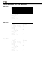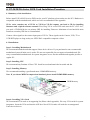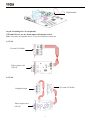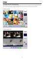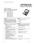
1
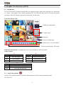
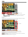
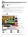
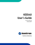
Network DVR on Chip Your best choice for digital video recording and remote surveillance VP-2x Series Cost-effective Video/Audio Capture Card Quick Reference Manual (Version:2.0) Introduction Specification Package Contents Installation Graphic User Interface (GUI) Appendix www.vpon21.com Preface Notice The information in this manual was current when published. The manufacturer reserves the right to revise and improve its products. All specifications are therefore subject to change without notice. Note: Formosa21 will not be obligated to the responsibility outside the scope of VPON DVR. Trademarks VPON ® is a registered trademark of Formosa 21 Inc. Microsoft, Windows, Internet Explorer ® are registered trademarks of Microsoft Corporation. Netscape, Navigator, Communicator ® are registered trademarks of Netscape Corporation. Other brand and product names referred to in this manual are trademarks or registered trademarks of their respective holders. Trademarked names are used throughout this manual. Rather than place a symbol at each occurrence, trademarked names are designated with initial capitalization. Inclusion or exclusion is not a judgment on the validity or legal status of the term. Warning To reduce risk of electric shock, do not remove cover. No user service-able parts inside. Refer servicing to qualified service personnel. Do not expose this appliance to rain or moisture. Do not install this product in hazardous areas where highly combustible or explosive products are stored or used. Severe impact or vibration may cause malfunction. Do not move this product when VPON is working. Position it in an open space with flat surface, and also maintain at least 15 cm between the left and right sides of the body and the wall. The lightning flash/arrowhead symbol, within and equilateral triangle, alerts the user to the presence of a shock hazard within the product’s enclosure. CE Warning This is a Class A product, in a domestic environment this product may cause radio interference in which case the user may be required to take adequate measures. FCC Warning This device complies with Part 15 of the FCC Rules. Operation is subject to the following two conditions (1) this device may not cause harmful interference, and (2) this device must accept any interference received, including interference that may cause undesired operation. GUARANTEE Every care has been taken in the preparation of this manual; if you detect any inaccuracies or omissions, please inform FORMOSA21, INC. in Taiwan or your local distributor. FORMOSA21 cannot held responsible for any technical or typographical errors and reserves the right to make changes to the products and manuals without your prior notice. FORMOSA21 makes no warranty of any kind with regard to the material contained within this document, including, but not limited, the implied warranties of merchantability and fitness for a particular purpose. FORMOSA21 shall not be liable nor responsible for incidental or consequential damages in connection with the furnishing, performance or use of this material. Important information Before proceeding, please read and observe all instructions and warnings contained in this manual. Retain this manual with the original bill of sale for future reference and, if necessary, warranty service. When unpacking your VPON unit, check for missing or damaged items. If any item is missing, or if damage is evident, DO NOT INSTALL OR OPERATE THIS PRODUCT. Contact your dealer or us for assistance. Table of Contents 1. VP-24/28/216 Introduction ---------------------------------------------------------------------------------1 1.1 Features------------------------------------------------------------------------------------------------------------1 2. VP-24/28/216 Series DVR Card Specification ------------------------------------------------------3 3. VP-24/28/216 Package Contents -------------------------------------------------------------------------4 4. VP-24/28/216 Series DVR Card Installation Procedure 4.1 Summary of the installation-----------------------------------------------------------------------------------5 4.2 Installation ------------------------------------------------------------------------------------------------------ 5 4.3 Power on --------------------------------------------------------------------------------------------------------9 4.4 Configuration -------------------------------------------------------------------------------------------------- 9 4.5 Connecting to network ----------------------------------------------------------------------------------------9 4.5.1 Remote access using dial-up ------------------------------------------------------------------------------- 9 5. About the GUI Introduction 5.1 The local GUI------------------------------------------------------------------------------------------10 5.2 The network GUI --------------------------------------------------------------------------------------------10 6. Graphic User Interface (GUI) 6.1 Introduction ---------------------------------------------------------------------------------------------------11 6.2 Setup Video Quality -----------------------------------------------------------------------------------------11 6.3 PTZ Control --------------------------------------------------------------------------------------------------12 6.4 Play Button ---------------------------------------------------------------------------------------------------13 Appendix Appendix A: Recommendation Motherboard --------------------------------------------------------------------I Appendix B: Watch-dog Wiring Description---------------------------------------------------------------------II 1. VP-24/28/216 Introduction A VP-2x series package includes one of VP-24 or VP-28 or VP-216 video capture card and a DVR on chip DOM (optional). After install them in a PC, it becomes a dedicated DVR system after power up. The DVR System is a high performance digital video recorder with built-in mini web server and real-time video capturing capability. The video is grabbed and compressed for faster transmission to your PC through 10/100Mbps Ethernet. The video also can display through local VGA output . Besides, VP-2x series supports digital recording function. It can record / playback / browse video simultaneously and save video data by cyclic recording to PC hard disk. VP-2x series supports motion live video and audio through Internet, Intranet connection. After installing VP-2x series, the PC is ready as a DVR. When power up, it starts local DVR functions such as monitoring through VGA output and recording to hard disk if it is configured to do that. For remote monitoring or access to historical data, you will have to set up the LAN or Internet environments and configure VP-2x series IP information. When all these installation are done successfully, VP-2x series delivers audio/video transmission to anywhere anytime. A PC with Internet browser and our proprietary plug-ins software can do that. The camera can be remotely controlled to do zoom in and out, and the unit can be triggered to initiate certain events. Configuration of VP-2x series can be done by an IR remote control unit (optional) or a mouse(default setting). 1.1 Features Video & audio live surveillance VPON Network DVR Firmware in a DOM (Disk On Module) Simple and smart operation with IR remote control. Up to 30 fps on each camera for local monitoring. Adjustable recording quality for each camera. Two-way audio transmission. 1 / 4 / 6 / 7 / 8 / 9 / 10 / 13 / 16 split-screen display. Control well known brand PTZ Cameras. Different PTZ devices can work on same serial bus. System log and Operation log support. Record / display / playback simultaneously. Local playback of recorded video on VGA or TV monitor . Remote live monitoring and playback from PC browser. High video quality and low data rate. Multiple video compression engines: MPEG4, H.263, JPEG, M-JPEG Recording & Playback Water mark to prevent fraud image modification Adjustable recording rates and resolution for each camera Motion detection / Alarm trigger / Cyclic / Schedule / Weight recording Pre-motion or pre-alarm and post-motion or post-alarm recording Adjustable recording frame rates when motion or alarm was triggered Brightness and color adjustment during playback Digital Zoom-in during playback Thumbnail browsing support Bookmark function support 1 Searching by time, day, motion, events or alarm log. SCSI/USB/IDE RAID and NAS storage system support Alarm function System automatically displays corresponding enlarged image when alarm is triggered Snapshot images through E-mail or FTP server when alarm is triggered. Voice call alert notification. Optional GPI/O for alarm control. Network Browser-based, no remote viewing software needed. Access prohibition for pre-defined hosts through IP network Dynamic IP support for Internet access Direct Dial-up available and Low-bandwidth support Easy to use Plug and recording, non-Windows embedded Linux system Easy configuration via local keyboard, IR Control, Home Page or Mouse Standard web browser as the client application Customization Supports HTML file upload for home page customization Supports FTP Server upload for customization Support backup configuration file Support POS / ATM integration 2 2. VP-24/28/216 Series DVR Card Specification Model: VP-24: Channels/Card CODEC Rec. FPS/Card(320x240) Rec. FPS/Card(640x480) MAX. Cards MAX. Channels Audio Recording Audio In/Card MAX. Audio In Audio Out MAX. Alarm In MAX. Control Out 4 S/W MPEG4 40fps 40fps 4 16 YES 1 4 1 16 8 Channels/Card CODEC Rec. FPS/Card(320x240) Rec. FPS/Card(640x480) MAX. Cards MAX. Channels Audio Recording Audio In/Card MAX. Audio In Audio Out MAX. Alarm In MAX. Control Out 8 S/W MPEG4 85fps 45fps 2 16 YES 4 8 1 16 8 Channels/Card CODEC Rec. FPS/Card(320x240) Rec. FPS/Card(640x480) MAX. Cards MAX. Channels Audio Recording Audio In/Card MAX. Audio In Audio Out MAX. Alarm In MAX. Control Out 16 S/W MPEG4 40fps 40fps 1 16 YES 4 4 1 16 8 Model: VP-28: Model: VP-216: 3 3. VP-24/28/216 Package Contents Please check your VP-2x series package for the following items: VP-24: 1. Capture card *1 2. Watchdog wire *1 3. Quick reference manual *1 4. CD *1 5. DOM Chip (Disk On Module) *1 Optional 6. I/O card *1 Optional 7. IrDA controller and receiver *1 Optional VP-28: 1. Capture card *1 2. Daughter board *1 3. Capture card connect to Daughter board cable *1 4. Watchdog wire *1 5. Audio cable *1 6. Quick reference manual *1 7. CD *1 8. DOM Chip (Disk On Module) *1 Optional 9. I/O card *1 Optional 10. IrDA controller and receiver *1 Optional VP-216 1. Capture card *1 2. Daughter board *3 3. Capture card connect to Daughter board cable *3 4. Audio card *1 5. Audio cable *1 6. Watchdog wire *1 7. Quick reference manual *1 8. CD *1 9. DOM Chip (Disk On Module) *1 Optional 10. I/O card *1 Optional 11. IrDA controller and receiver *1 Optional 4 4. VP-24/28/216 Series DVR Card Installation Procedure 4.1 Summary of the installation: Before install VP-24/28/216 series DVR card to your PC platform, please make sure the PC’s Hardware is compatible with the motherboards, which we have recommended in the appendix. VP-2x series contains one of VP-24 or VP-28 or VP-216 capture card and a CD for installing firmware and a Quick reference manual. First, Plug VP-2x series DVR card onto the PC’s PCI slot , you need a CD-ROM device on primary IDE for installing Firmware. Maximum of two hard disk units install on secondary IDE slot is recommended. Connect video signals to the camera input ports of VP-2x. These signals can be Camera, VCR, TV or VCD/DVD player as long as they are NTSC/PAL compatible composite videos. 4.2 Installation: Step 1 : Installing Motherboard We recommend motherboards that support Linux device drivers. If you purchased a non-recommended motherboard yourself make sure it works. We are not responsible for non-approved motherboards. We carry recommended motherboards for system integrators to use. Put the motherboard together just like a regular PC. Step 2: Installing CPU We recommend any Pentium 4 Class CPU. Install as usual and attach the heat sink and fan. Step 3: Installing Memory We recommend installing a good brand name 256MB DDR memory. Note: If you choose MPEG4 compression Standard, please install 512MB DDR memory. DDR Memory Step 4 : Installing VGA Card We recommend VGA cards as in supporting list (Please check appendix) .We carry VGA cards for system integrators. Insert the VGA card into the AGP slot. Not all VGA cards will work due to unsupported Linux device drivers. 5 Step 5: Installing VP-2x Capture Card Our capture card is proprietary and will only work with our DVR firmware. Install the capture card into an available PCI slot. Once the system boots the VPON firmware will automatically detect how many capture cards are in the PCI slots. Capture card Step 6: Installing the hard drives For a single drive make sure the jumper settings is set on primary. Attach that with any ordinary IDE cable onto the secondary IDE channel. For dual drives make sure one hard drive is set on primary and the secondary on slave. Attach those to the IDE cable and plug into the secondary IDE channel. You can also install 2 HDD on primary IDE after completion firmware installation. Please refer to Step 7. The max hard drive size supported is 500GB each. For a total of 2TB including firmware space. Step 7 : Installing CD-ROM, Keyboard and mouse Install a CD-ROM for installing Firmware from CD. After installing Firmware you can remove the CD-ROM and change to Hard disk for extend your storage size (max 4 hard disks total system). Or Installing the VP-20 DOM module The VP-20 DOM module sits on the primary IDE slot on the motherboard. If attaching a CD-RW to your unit then put the VP-20 DOM module in the middle of the yellow IDE cable included. And then put the end of the yellow IDE cable to the CD-RW and the other end to the primary IDE channel. The yellow IDE cable must be used with the VP-20 DOM module and not any generic IDE cable. Then attach the power connector from the VP-20 DOM module to a free lead from the power supply. Note: DOM module (Model: VP-20) is an optional device, if you need it please contact us. When install DOM on primary IDE, you can NOT install HDD on the same IDE slot. This makes totally 2*HDD per PC DVR system. 6 DOM module Step 8 : Installing I/O Card (Optional) GPI and GPO are use for alarm inputs and outputs control. Note: I/O card is an optional device, if you need it please contact us. 1) VP-24 I/O card (VP-IO84) Video capture card (VP-24) 2) VP-28 I/O card (VP-IO84) Daughter board Video capture card (VP-28) 7 3)VP-216 Audio card Daughter board I/O card (VP-IO84) Video capture card (VP-216) Step 9 : Power On and Install Firmware After complete hardware installation, you can power on the PC as usual and follow the procedure below for firmware installation: 1. Before install Firmware, enter BIOS first and select First boot device to CD-ROM. After boot up your system, you will see as follow: 2. DVR INSTALL 3. Select a disk to install. HDS722540VLAT20(hda) HDS722540VLAT20(hdb) USE: UP , Down , Enter , ESC Note: If user has two Hard Disks, you can choose to install Firmware to the hard disk you want. 4. Press enter -> Format disk hda (Y/N)? Y ->Installing files ->The installation has finished ->Press any key to reboot. Note: After system reboot, please remove CD from CD-ROM otherwise firmware will ask you to install again. 5. After installing Firmware, Live videos should be displayed on VGA screen if everything is OK. 6. Click Setup button on the right panel to show setup menu .Select the System Info function in the menu to display the system information such as disk size or firmware information . 7. If you want to install more Hard disk to your DVR system, you can remove the CD-ROM and install 2*Hard disks on primary IDE. 8. When you power on the DVR system, please enter BIOS first and select “First boot device” hard disk which you selected to install firmware. 8 4.3 Power On After complete the installation , you can power on the PC as usual. Live videos should be displayed on VGA screen if everything is OK. 4.4 Configuration When you get videos displayed on VGA screen, you can configure the VP-24/28/216 PC DVR unit using mouse or the IrDA controller(optional) comes with the VP-24/28/216 package. Please refer to User manual “Chapter 3 operating VPON by mouse . 4.5 Connecting to the network Connect an Ethernet-capable computer to the VPON LAN port using an RJ-45 crossed UTP cable or connect both of the PC and VPON to a same hub : 1. The default IP address for the VPON is 192.168.10.10. Set your PC IP address to 192.168.10.xxx (where xxx is a value between 0 ~ 254). Set the subnet mask to 255.255.255.0. 2. Reboot the PC. 3. Use IE Web browser version 6.0 SP2 up to access http://192.168.10.10. The login dialog box will appear. If you have previously changed the administration login or password, enter the login name and password you previously set. Otherwise, enter the default login name webmonitor and the password oyo then click OK. 4. For first time accessing VPON , you will be prompted to install Live Video ActiveX. Download and run the file to install ActiveX. Then restart IE browser, you will be able to see the videos. If you choose not to install Active X, you can view videos from the VPON by clicking on the View Video without Plugins link at the bottom of the page. At the prompt, enter the same administrator login name and password as before. This uses a Java applet to display the video. 4.5.1 Remote access using dial-up You can access the VPON remotely without the Internet by using a dialup modem. The VPON must be working under Network mode. 1. Connect a dial-up modem and phone line to the VPON COM1 port. 2. Set COM1 to modem device in the VPON system menu. 3. On the remote PC, create a new dial-up setting (Windows). 4. Set the protocol to PPP. 5. Clear all advanced options and allowed network protocols except TCP/IP. 6. Set the IP address to 10.0.0.2. 7. Put a check mark in the server assigned server address box, uncheck “use IP header compression” and “use default gateway” on the network boxes. Then click OK. 8. Enter the number of the phone line connected to the VPON, as well as the administrator user name and password. 9. To access the VPON, use IE 6.0 SP2 up. Bring up IE on the PC and then access to 10.0.0.1. Note: As this is a PPP connection, only one user can access the VPON at a time. 9 5. About the GUI Introduction The VP-24/28/216 can be configured and operated using either the local GUI, or over a network. 5.1 The local GUI 5.2 The network GUI 10 6. Graphic User Interface (GUI) 6.1 Introduction VP-24/28/216 can be configured using either the supplied remote control unit (optional) (or a keyboard) or a mouse. This chapter covers mouse operation. The VP-24/28/216 must be in GUI mode for mouse operation. Under GUI mode, keyboard is used ONLY for data entry. Local surveillance GUI: DVR basic information Camera status Playback System configuration Split-screen / Live surveillance Full screen monitoring / I/O button DVR basic information: including date, time, total hard disk size and LAN status. Camera status: R M Color Recording Mode Color Motion detection Status Gray No video signal Gray Motion not detected Blue No recording Yellow Motion detected Red Full recording G Color Status of each DI and DO device. Gray DI or DO not detected Red DI or DO was detected 6.2 Setup Video Quality Use the video quality button to set all the video parameters for the cameras connected to the VP-24/28/216. 11 1. First, please change to single screen as following . Select camera Video quality button / I/O button / POS button Back to live surveillance / Enlarge video / System setup 6.3 PTZ Control PTZ panel Use the PTZ panel to control PTZ (Pan, Tilt, Zoom) cameras. This panel is displayed when change to single screen. User can setup PTZ model in the “camera setup section”. PTZ panel PTZ panel: You can do preset and recall, zoom in/out, focus, iris control to current camera. Preset buttons- Save current camera position. You can save totally16 preset positions Recall buttons- Move the camera to the selected preset position. ZOOM buttons - adjust the zoom to provide a more closer or wider view of the subject. FOCUS buttons - adjust the focus of the camera. 12 Speed buttons - Adjust the moving speed of the selected PTZ camera. PTZ OSD menu / patrol / auto pan – Using OSD menu to control PTZ . The “ ” button is ok,” ” button is cancel. Pan and tilt buttons - Adjust the pan and tilt of the selected camera include 45 degree directional PTZ control at upper right, upper left, button right, button left of PTZ control panel To set a camera configuration: 1. Select a camera using the numbered buttons (1~16) on the Surveillance Panel. 2. Adjust the Zoom, Focus, Speed, Pan and Tilt buttons until the camera is configured correctly. 3. Press a Set button to save the configuration. The configuration you have saved can now be recalled with the corresponding Call button. 6.4 PLAY button Click the PLAY button for playback the recorded files in the hard disk. Watermark Calendar Function buttons Play buttons Split-screen buttons Recording data status information Lock file Back to live surveillance Function buttons: 1. Bookmark 2. 4. Thumbnail Browse 5. Alarm log Search by Event 3. 6. Backing up the data Search by Text Note: For more information, please refer to User manual “Chapter 3 Graphic user interface” in CD. 13 Appendix A: Recommendation Motherboard We have tested some different motherboards for VP-24/28/216. If You are first time to plug and play VP-24/28/216.We suggest you to choose the motherboard which have been tested by us for better performers。 Suggesting CPU model: Pentium 4, 1.6G or better Motherboard: 1. North bridge:Intel chipset 2. South bridge:ICH2, ICH4, ICH5 & ICH5R 3. Others: We need 5 PCI slots at the least for expand Memory : DDR 256MB or above DDR512MB for MPEG4 compression standard AGP VGA Card: nVidia Gforce4 MX400 / MX440 / MX4000(support TV-OUT) ATI Rage 128 / ATI 9200 / ATI 7000 (ATI no support TV-OUT) PCI-Express VGA Cards : nVidia Geforce NX62/00/NX6600 (mouse mode only) ATI X300SE (VGA Monitor only) Motherboard: Socket 478 Motherboards* (M/B) Motherboard Brand & Model # Asus P4P800-SE Asus P5P800S Asus P4P800-MX (Micro ATX, 3xPCI) MSI Neo2-V MSI 865GM2-LS (Micro ATX, 3xPCI) Albatron PX865PEC Pro Chipset Intel 865PE Intel 848P ICH5 Intel 865PE Intel 848P ICH5 Intel 865G (integrated graphics support) Intel 865PE Socket 775 Motherboards* (M/B) Motherboard Brand & Model # VPON VP-MB945G GIGABYTE GA-8I945P-G GIGABYTE GA-8I915P DUO Intel D915PCY (VP-2x Only) Asus P5P800 SE Gigabyte GA-8I848P MSI Neo3-V MS-7097 Ver1 N1996 Albatron PX865PEC Pro Chipset Intel 945G Intel 945P Intel 915P Intel 915P Intel 865PE Intel 848P Intel 865PE Intel 865PE *Supported motherboards as of April 20, 2006 I Appendix B: Watch-dog Wiring Description Watch dog is a hardware device to monitor the system status. If the system fails to response, Watch dog will send a rest signal to the motherboard to reboot the system. To enable Watch dog function, please select available durations 100,99,98…..8 seconds. Hardware Request list: One pair of conducting wire (2-pin to 2-pin). Installation Step: Attach the pair of conducting wire from video capture card JP1 PIN1,2(+,-) to the RESET JUMPER(+,-) on Motherboard. Video capture card JP1 PIN1,2 <========> RESET JUMPER on Motherboard Pair of conducting wire 1. Use a RS232 null modem cable to build up the connection between COM1 port of PC and VPON. 2. Run WCOMW.EXE and it will show up the “Network Mode Configuration Menu”. As bellow : 3. Select the item 7 on “Network Mode Configuration Menu” then press “Enter”, it will do watchdog functional test in VPON and display message "100 99 98 97 ………..8 !" on the screen. 4. Exit Configuration Menu to stop WCOMW.EXE, When DVR reboot to ready, the test is completed. II