1
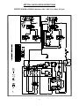
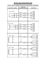
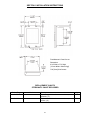
OWNER’S MANUAL
E L E C T R I C S T E R I L M AT I C S T E R I L I Z E R
MODELS:
□ STM-E
□ STM-EL
EXPORT MODELS:
□ STM-EX
□ STM-ELX
• INSTALLATION
• OPERATION
• MAINTENANCE
• TROUBLE-SHOOTING
• PARTS & SERVICE
• WARRANTY
35 Garvey Street, Everett, MA 02149
Telephone: (617) 387-4100, (866) 698-3188
Fax: (617) 387-4456, (800) 227-2659
[email protected], www.mfii.com
H-2115
08/11
REV. C
TABLE OF CONTENTS
SECTION 1 INSTALLATION INSTRUCTIONS
SERVICE & TECHNICAL INFORMATION CONTACT...... 1
OPERATION ENVIRONMENTAL CONDITIONS.............. 1
INTENDED USE - DUTY CYCLE...................................... 1
INSTALLATION ................................................................ 1
ELECTRICAL ................................................................... 1
OUTSIDE VENTING ........................................................ 1
WATER-COOLED EXHAUST CONDENSER .................. 1
RECORDING THERMOMETER ...................................... 1
TRAY SUPPORTS ........................................................... 1
BAFFLE INSTALLATION . ................................................ 1
OPERATION CHECK ....................................................... 1
INSTALLATION INSTRUCTIONS FOR COLD WATER
CONDENSER .................................................................. 2
REQUIRED CONNECTIONS ........................................... 3
INSTALLING PAN SUPPORTS AND BAFFLES .............. 4
ELECTRICAL SUPPLY CONNECTIONS FOR
STM-E & STM-EL.............................................................. 4
ELECTRICAL SUPPLY CONNECTIONS FOR
STM-EX & STM-ELX ........................................................ 4
DOMESTIC WIRE DIAGRAM FOR STM-E & STM-EL .... 5
EXPORT WIRE DIAGRAM FOR STM-EX
& STM-ELX ...................................................................... 6
TYPICAL CIRCUIT CONNECTION FOR STM-E
& STM-EL ......................................................................... 7
TYPICAL CIRCUIT CONNECTION FOR STM-EX
& STM-ELX EXPORT . ..................................................... 8
INSTALLATION FOR OPTIONAL RECORDING
THERMOMETER ............................................................. 9
TO REMOVE THE CHART .............................................. 9
TO INSTALL NEW CHART . ............................................. 9
THERMOMETER DIMENSIONS.......................................10
REPLACEMENT PARTS FOR 24 HOUR
THERMOMETER .............................................................10
SECTION 2 WATER CONDITIONS .................................11
DOOR ASSEMBLY PARTS LIST . ....................................15
THE DOOR GASKET .......................................................15
DOOR LIFT SPRING .......................................................15
TO REMOVE THE DOOR ASSEMBLY ............................15
THE FULCRUM AND DRAIN ASSEMBLY .......................16
ROLLER ASSEMBLY .......................................................16
FULCRUM AND DRAIN PARTS LIST ..............................16
DOMESTIC – THE PRESSURE ACTUATED
TEMPERATURE CONTROL, STM-E & STM-EL .............17
DOMESTIC – HOW IT WORKS .......................................17
DOMESTIC – ADJUSTING THE RANGE
OR OPERATION, STM-E .................................................17
EXPORT - THE PRESSURE ACTUATED
TEMPERATURE CONTROL, STM-EX & STM-ELX ........17
EXPORT – HOW IT WORKS ...........................................17
EXPORT – CHECKING THE 100oC SETTING,
STM-ELX ..........................................................................17
EXPORT – ADJUSTING THE RANGE
OF OPERATION, STM-ELX .............................................18
DOMESTIC – CHECKING THE 230o
SETTING, STM-EL . .........................................................18
DOMESTIC – ADJUSTING THE RANGE
OF OPERATION, STM-EL ..............................................18
CAST-IN THE HEATING ELEMENTS ..............................18
THE LOW WATER CUT-OFF (MANUAL RESET) ...........18
THE ELECTRIC CONTACTORS . ....................................18
THE TIMER ......................................................................18
THE STEAM PRESSURE GAUGE ..................................19
THE SAFETY VALVE .......................................................19
THE FLUE ........................................................................19
THE EXHAUST SOLENOID VALVE . ...............................19
TO REPLACE A THERMOSTATIC ELEMENT .................19
THE STEAM TRAP ..........................................................19
HOW IT WORKS ..............................................................19
SECTION 6 ILLUSTRATED PARTS
DAILY CLEANING PROCEDURE ....................................13
Parts Illustration for STM-E(L) &
STM-E(L)X ....................................................................... 20
& 21
Parts Illustration for STM-E & STM-EX ........... 22
Parts Illustration for All Models ................... 23
& 24
Control Panels.......................................................... 25
Door Handle ...............................................................26
& 27
MISCELLANEOUS PARTS (NOT SHOWN) .................... 28
SECTION 5 FIELD SERVICE INSTRUCTIONS & ASSEMBLY
SECTION 7 TROUBLE SHOOTING
STERILMATIC OPEN STAND . ........................................14
PARTS LIST FOR CONDENSER WITH OPTIONAL
STAND .............................................................................14
DOOR ADJUSTMENT . ....................................................14
STERILMATIC DOOR ASSEMBLY ..................................15
STEAM TRAP TROUBLE-SHOOTING ............................29
TROUBLE-SHOOTING GUIDE . ......................................29
SECTION 3 OPERATING INSTRUCTIONS
OPERATING INSTRUCTIONS ........................................11
STERILIZATION GUIDE ..................................................12
MINIMUM STERILIZATION TIMES . ................................12
SECTION 4 MAINTENANCE
SECTION 8 WARRANTY INFORMATION . .....................30
SECTION 1 INSTALLATION INSTRUCTIONS
AUTOMATIC STERILMATIC STEAM
PRESSURE STERILIZER
ELECTRICAL
Connect to proper electrical supply box and disconnect
switch as shown on one of the following schematic diagrams - 208 or 240 volts, single or three phase. Connection is made from the rear of the unit, through the
conduit to the terminal box located at the front of the
unit. See installation specifications on page 5.
MODELS: STM-E, STM-EL, STM-EX & STM-ELX
SERVICE & TECHNICAL INFORMATION CONTACT
NOTE: This unit should be serviced by qualified
service personnel only.
OUTSIDE VENTING
Your Sterilmatic Sterilizer has been developed to
answer the need for a compact, automatic, lowcost steam pressure sterilizer. The following instructions cover installation. Should service be
required, it is readily available by contacting our
authorized service agency located nearest to you.
The name of your local service company can be
obtained by contacting the Service Department at
Market Forge., Telephone (617) 387-4100 or via
e-mail [email protected].
Connect 1/2” (13mm) nominal tubing exhaust to outside vent connection located on top of unit, within the
control housing. IMPORTANT: Exhaust line must be
vented to the outside to eliminate the exhausted steam
and the accompanying noise from entering the room.
Use 1/2” (13mm) copper tubing or suitable alternate.
The overall height and length of the line should not rise
more then 4 feet (1.2 meters) above the unit and exceed 15 feet (4.5 meters) with a minimum of bends.
The line should slope downward after leaving the sterilizer in order to insure condensate drainage.
OPERATING ENVIRONMENTAL CONDITIONS
This unit is designed for commercial use and to be
safe at least under the following conditions:
• For indoor use only.
• For use at altitudes up to 6500ft (2000m)
• For use at temperatures from 41oF (5oC) to 104oF
(40oC).
• Maximum relative humidity 80% for temperatures
up to 88oF (31oC) decreasing linearly to 50% relative humidity at 104oF (40oC).
• Main supply voltage fluctuations not to exceed ±
10% of nominal voltage.
• Transient overvoltages according to Installation
Categories II (in accordance with IEC 664).
• Pollution Degree 2 (in accordance with IEC 664).
WATER-COOLED EXHAUST CONDENSER
If outside venting is not possible, an optional watercooled condenser is available for connection to an
open drain. If required order part no. 95-0436 kit.
RECORDING THERMOMETER
If a recording thermometer is provided, refer to installation guide provided with recorder.
TRAY SUPPORTS
Install side tray supports. Tray supports are attached
by means of key-hole clearance slots which are slipped
over studs located on the sides of the Sterilmatic chamber.
BAFFLE INSTALLATION
INTENDED USE - DUTY CYCLE
This unit is intended to be operated intermittently.
After a pre-heat cycle, the longest period of use
is 60 minutes. The timer allows a maximum of 60
minutes. After each use the unit should be opened
for removal and reloading of product. The water
level should be checked after each use and refilled when necessary.
To insure maximum drying of packs, a baffle is supplied
with your Sterilmatic. Place perforated splash baffle in
bottom of the sterilizing chamber. Install small baffle
with no perforation at the rear of the upper tray support
channel.
NOTE: The perforated baffle is not to be used as
a shelf to place media or other items. It is intended
to eliminate splashing.
INSTALLATION
OPERATION CHECK
Set sterilizer on counter, using the 6” (152mm) legs
provided or assemble the optional stainless steel stand
with under-shelf. If your Sterilmatic includes a watercooled exhaust condenser, we recommend the use
of the Sterilmatic stand, part number 95-6060. First,
level unit in place, then adjust rear legs to pitch the unit
forward 1/4” (6mm) to insure positive drainage of the
cylinder.
To check for proper operation of unit:
1. Close drain valve by turning handle clockwise.
WARNING: DO NOT OPEN DRAIN VALVE WHILE
UNIT IS OPERATING. PREMATURE OPENING
MAY RESULT IN SCALDING OF OPERATOR.
1
2. Fill chamber with 4 to 6 quarts (3.7 to 5.6 liters) of
ordinary tap water. DO NOT USE DISTILLED OR
DEIONIZED WATER.
SECTION 1 INSTALLATION INSTRUCTIONS
COLD WATER CONDENSER
3. Close chamber door.
PART
NO.
QTY.
4. Set exhaust selector to INSTRUMENTS AND
PACKS (fast exhaust) or LIQUIDS (slow exhaust).
ITEM
5. Set timer to 15 minutes. Cycle will go to completion
automatically.
1
95-2119
2
95-2219 Thermostat Box Assy.
3
95-0086 Exhaust line
5
15-7057 Copper tubing 3/8 OD
6
10-1775 Rd. Hd. Mach. Screw, 1/4-20
2
7
10-2500 Lockwasher, 1/4
2
8
10-2308 Hex Nut, 1/4-20
2
9
10-1812 Rd. Hd. Mach. Screw, 10-32
2
10
10-2505 Lockwasher, 10
2
11
10-2340 Hex Nut, 10-32
2
12
95-4009 Front Template (7” Lg)
1
13
95-4010 Back Template (11” Lg)
1
NOTE: Cycle timer will not start until sterilizing
temperature is obtained.
AMPS PER WIRE *STERILIZER
Phase
3 Phase
1 Phase
Volts
208
240
208
240
Amps
26
30
45
52
DESCRIPTION
Steam condensing unit
1
1
1
22.25”
SERVICE CONNECTIONS REQUIRED
208V (197-219)
or
240V (220-240)
A
1/2” IPS Cold Water Connection
B
1” IPS Drain Connection (See Note 3)
C
115V Elec. Connection 7/8 Ø knockout (cond. unit)
D
NOTES:
1. Unit must be grounded and all wiring to comply with local codes.
2. Pipe to open drain. Do not make solid connection to sewer.
3. Condensing unit to be installed as to have a back to front pitch.
2
Electrical Connection
SECTION 1 INSTALLATION INSTRUCTIONS
REQUIRED CONNECTIONS:
A
Drain - 1/2” (13mm) FPT of 5/8” (16mm) OD
copper (see note 1)
B
Steam Exhaust Connection - 3/8” (10mm) IPS
(see note 2)
C
Electrical Connection - (*see table below)
D
Power Supply
*AMP/PHASE
MODEL
Single Phase Three Phase
kW
Hz
STM-E(L)
9
60
45A
52A
-
-
STM-E(L)
12
60
-
-
26A
30A
208V
240V 208V 240V
UNIT MUST BE GROUNDED.
MAIN SUPPLY VOLTAGE FLUCTUATIONS ARE NOT TO
EXCEED ± 10% NOMINAL SUPPLY VOLTAGE
NOTES:
1. An air break must be provided if a unit drain line is run.
2. Vent exhaust to atmosphere. B1 is actual connection,
but must exit casing at B. IMPORTANT: Exhaust line must be vented to the outside to eliminate the exhaust steam and the accompanying noise from entering the room. Use 1/2” (13mm)
copper tubing or suitable alternate. The overall height
and length of the line should not rise more then 4’ (1.2
meters) above the unit and exceed 15’ (4.5 meters) with
a minimum of bends. The line should slope downward
after leaving the sterilizer in order to ensure condensate
drainage.
IMPORTANT: Failure to comply with this outline will affect the sterilization process.
When an exhaust condenser is supplied; the following
services must be provided: 1/2” (13mm) IPS cold water:
1” (25mm) IPS waste: 115V electrical line.
3
SECTION 1 INSTALLATION INSTRUCTIONS
INSTRUCTIONS FOR INSTALLING PAN SUPPORTS AND BAFFLES
1. Locate the mounting studs on the inside of the chamber. There are two rack mounting studs on each side
(see Fig. 1).
2. Taking one pan support and positioning rack so that the pan stop is facing the rear of the unit and the wires
are facing toward the center of the unit. The pan stop is a piece of sheet metal welded to the rack with a 65° bend.
3. Begin to hang the pan support by placing the rear key-way slot onto the rear mounting stud and slide the rack
until the slot sits on the mounting stud. When this is done correctly the front mounting stud will be in position
to place the front key-way slot. Slide the rack down into its correct position (see Fig 2).
4. After installing one pan support rack correctly, you can install the upper baffle. Position the baffle so that the
45° bend is facing up towards the front of the unit (see Fig. 3). Slide the mounting tab onto the flat bend on
the pan stop bracket. The baffle should now stay in place by itself, but in a tilted state (see Fig. 4).
5. Position the second pan support rack into the cavity and slide the other mounting tab onto the rack flat bend
while the pan support rack is not on the mounting studs. Hang the pan support by placing the rear key-way
slot onto the rear mounting stud and slide the rack until the slot sits on the mounting stud. When this is done
correctly the front mounting stud will be in position to place the front key-way slot. Slide the rack down into
its correct position.
6. Place the Perforated Water Baffle so that it sits on the bottom of the inside of the sterilizer chamber (see Fig. 5).
7. CAUTION: Do not cover the holes in the Perforated Water Baffle by using it as a shelf. This will result in a
disrupted flow of steam.
THE ELECTRIC SUPPLY CONNECTIONS FOR STM-E AND STM-EL: Connect to proper electrical supply as
indicated on nameplate on top of unit. The power supply cord is brought in from the rear of the unit, through the
conduit and the connection is made at the terminal box located at the front of the unit.
THE ELECTRIC SUPPLY CONNECTIONS FOR STM-EX AND STM-ELX EXPORT: Connect to proper electrical
supply as indicated on nameplate on top of unit. Connection is made from the rear of the unit, through the conduit
to the terminal box located at the front of the unit. All control circuits are 220 volts.
In order to accomplish this, a current-carrying grounded neutral must be provided.
Thus, a three phase system must be 4-wires. Most electrical codes require, and we recommend, that a separate
switch be located within sight of the sterilizer.
4
SECTION 1 INSTALLATION INSTRUCTIONS
STM-E & STM-EL Sterilizer: 208V - 240V / 120V, 3 Ø - 4 Wire
5
SECTION 1 INSTALLATION INSTRUCTIONS
EXPORT STM-EX & STM-ELX Sterilizer: 220V / 380V, 3 Ø - 4 Wire, 50 Cycle
6
SECTION 1 INSTALLATION INSTRUCTIONS
7
SECTION 1 INSTALLATION INSTRUCTIONS
8
SECTION 1 INSTALLATION INSTRUCTIONS
INSTALLATION FOR OPTIONAL RECORDING
THERMOMETER: The optional Recording Thermometer may be surface or panel mounted whichever is
preferred.
1. Remove the top cover of the sterilizer. Remove
the pipe plug located in the T-fitting that also accommodates the safety relief valve and which is
connected directly to the sterilizing chamber. (See
figure to the right)
TO REMOVE THE CHART:
1. Unscrew and remove the chart ‘hub’ knob (attached to the chain).
2. Insert the RTD temperature sensor of the temperature recorder through the rectangular cutout in the
top cover then into the pipe from which the plug
was removed.
2. Locate the center hole of the chart over the center, threaded rod. Rotate chart to line up the current time of day directly underneath the stylus print
head.
3. Make sure RTD temperature sensor is protruding
down into the sterilizer cavity but not too much so
as to interfere with the sheet metal baffle plate.
Tighten the compression fitting. Replace top cover
onto the sterilizer.
3. Screw the chart ‘hub’ knob back in place, hand
tight only.
2. Grasp the edge of the chart and lift straight off.
TO INSTALL A NEW CHART:
1. Slide edge of the chart under the two raised tabs
located under the stylus.
4. For mounting the recorder on a wall, refer to the
recorder manual supplied with the recorder.
5. Electrical connections: The 115/120VAC unit comes
with a 6’ power cord and three prong plug. This can
be plugged into any 120V outlet. The 220/230VAC
unit comes with a 6’ power cord and three prong
plug. However, due to the many varieties of plugs
and outlets you may need to replace the plug with
the appropriate plug.
The Future Design Recording Thermometer is a 24hour clock and should be run continuously.
Charts should be changed every 24 hours.
Remove Plug
9
SECTION 1 INSTALLATION INSTRUCTIONS
Flush Mounted - Panel Cut-out
Dimensions:
6-3/4” Wide x 7-7/8” High
[171mm Wide x 200mm High]
7/32” [6mm] Ø at Corners
REPLACEMENT CHARTS
STERILMATIC CHART RECORDER
Market Forge
Vendor
Description
Qty.
10-7933
Replacement 24 hour thermometer charts,
farenheit, (oF)
50/box
08-6244
Replacement 24 hour thermometer charts,
celsius, (oC)
50/box
10
SECTION 2 WATER CONDITIONS
Market Forge from time to time is asked the question
about using distilled or deionized water for use with our
Sterilizer models STM-E and STM-EL. We are always
asked why these water choices are not allowed for use
with our units and what would be recommended. To
address this situation, we have complied the following
as a means of satisfying these questions:
fect the life to the aluminum cylinder. The pH range
that would be recommended is between 7.0-8.5.
•
The lack of a positive electrical ground can cause
an electrolytic reaction that will accelerate pitting.
•
Another contribution to accelerate pitting is the
type of cleaning solutions used or the abrasive
scrubbing pads. If a low pH is present with the detergents being used or an abrasive pad, the protective Alclad coating will be removed during the
cleaning process.
•
Spillage of media being sterilized can also contribute to the accelerated pitting if it is corrosive.
•
CHLORINE LEVEL ≤ 1 PPM.
1. We have found that the use of distilled or deionized
water will aggressively attack the pure coat of Aluminum Alclad, which protects the bottom surface
from oxidizing and then eventually pitting (reference: Operating and Maintenance Instructions).
2. In addition pitting can also be caused by several
other external environmental factors. Few examples are as follows. These conditions have been
highlighted in our documentation.
•
Grains of hardness in the water supply should be
as follows (.25 to 2).
•
A pH imbalance in the water supply can greatly af-
IMPORTANT NOTE:
Market Forge will not be responsible for damage
resulting from the use of hard or corrosive water,
from failure to drain the unit daily, or from inadequate cleaning procedures.
SECTION 3 OPERATING INSTRUCTIONS
quired times in the sterilization guide and times
table.) NOTE: In no case should the timer be set
to less than 15 minutes. Sterilization will not be
accomplished in less than 15 minutes exposure
time.
OPERATING INSTRUCTIONS:
1. IMPORTANT: Make sure the drain valve is closed.
Fill bottom of the sterilizer chamber with approximately six quarts of water or just below ledge at
bottom of door opening. (If water supply is known
to be hard or corrosive, a source of treated water
should be used.) DO NOT USE DISTILLED OR
deionized WATER. (See section 2)
6. TURN TIMER: Located at upper right front of
sterilizer. Select desired length of sterilizing period. This turns power supply on and starts the cycle
after pressure-temperature combination has been
reached. Amber pilot light indicates that the timer
is running.
2. LOAD STERILIZER: Use proper sterilizer load-
ing procedures when placing materials in sterilizer
chamber. All solid containers or instruments must
be placed so that water or air will not be trapped
in them.
7. When the sterilizer chamber reaches the selected
temperature, the timed exposure cycle will begin.
When the exposure cycle is completed, the electric supply will be opened automatically. When
the chamber pressure gauge located at the top
of the control housing reads “0”, the door may be
opened. (Release handle and let go to avoid possible contact with remaining steam.) When opening
the door, allow a few seconds for steam to escape
from chamber before opening completely.
3. CLOSE DOOR: Grasp handle, and holding it
in vertical position, pull door down until bottom of
door rests in the bottom of door opening. Then
rotate handle forward, engaging the lower curved
portion under the horizontal rod in the casting at
the bottom of the door opening. Push handle all the
way down and back until door is locked securely in
position.
8. To assist in drying racks, release door handle after pressure has been attained at start of cycle.
Pressure in chamber will keep door closed. The
use of a wire basket will provide better drying for
dressings. At end of sterilizing cycle, release door
handle and open slightly. Do not lift door to open
position. This will allow steam and moisture to escape. Allow door to remain in this position for 15
to 20 minutes before removing load. Small packs
can be dried successfully with this procedure. We
4. SET EXHAUST SELECTOR: Located at cen-
ter of the control housing mounted on top of the
unit, to correct position. Unit is now ready to start.
All items, other than solutions, may be sterilized
with selector at “Instruments”. Solutions require a
low exhaust. Place selector at “Liquids”.
5. DETERMINE CORRECT STERILIZATION
TIMES: (Referring to page 11 for minimum re11
SECTION 3 OPERATING INSTRUCTIONS
do not recommend the sterilization of large packs,
such as linens. Be sure condensate baffles are in
position in the chamber.
trays having mesh or perforated bottoms. Place
trays flat on shelves.
•
COMBINING FABRICS & HARD GOODS:
9. Remove load and check water level for next operation.
•
PLASTIC UTENSILS: DO NOT stack or nest
STERILIZATION GUIDE:
• PACKS (Linens, gloves, etc.): Use wire basket
•
LIQUIDS: Sterilize medium liquids separately
•
SMALL ITEMS: Sterilize small items in baskets,
to facilitate drying. Be sure condensate baffles are
in place. Place packs on edge and arrange load in
chamber, so that only minimal resistant to passage
of steam through the load will exist. NOTE: Place
gloves in upper two-thirds of chamber.
•
•
Place hard goods on lowest shelves.
plastic items.
from other supplies or materials. Set exhaust selector to proper position (liquids).
or trays.
JARS, CANISTERS (etc.): Place containers on
side to allow for displacement of air and complete
contact of steam to surfaces. Drying is also facilitated.
•
PETRI DISHES, PIPETTES, DESICCATORS
(etc.): Should be inverted.
UTENSILS, TREATMENT TRAYS: Placed on
•
INSTRUMENT SETS: Place instruments set in
NOTE: IF THE EQUIPMENT IS USED IN
A MANNER NOT SPECIFIED BY THE
MANUFACTURER, THE PROTECTION
PROVIDED BY THE EQUIPMENT MAY BE
IMPAIRED.
edges to facilitate drying.
MINIMUM STERILIZATION TIMES
TIME (Minutes)
ARTICLES
15
•
•
•
•
•
Glassware, empty, inverted.
Instruments, metal in covered or open tray, padded or unpadded.
Needles, unwrapped.
Pipettes, blood diluting, serological, volumetric, etc
Tubing glass (6mm), (10mm) inverted
20
•
•
•
•
Flasked solutions 75-250 ml.
Instruments, metal combined with other materials in covered and/or padded tray.
Instruments wrapped in double thickness muslin.
Rubber gloves, catheters, drains, tubing, etc. Unwrapped or wrapped in muslin or
paper.
30
•
•
•
•
•
Brushes in dispensers, in cans of individually wrapped.
Dressings, wrapped in paper or muslin, small packs only.
Flasked solutions 500-1000 ml.
Syringes, unassembled, individually packaged in muslin or paper.
Needles, luer, individually packaged in glass tubes or paper.
45
•
Flasked solutions 1500-2000 ml.
12
SECTION 4 MAINTENANCE
DAILY CLEANING PROCEDURE (AT THE END OF EACH DAY):
1. Remove bottom splash baffle.
NOTE: IMPORTANT! STERILIZING CHAMBER MUST BE CLEANED AND DRAINED DAILY USING THE FOLLOWING PROCEDURE. WASH WETTED PORTION OF THE CYLINDER THOROUGHLY BY ADDING A MILD DETERGENT TO WATER IN CYLINDER.
2. If a soft cloth or brush is used with the detergent and does not completely remove the surface film, a nylon
soap pad should be used. After washing thoroughly rinse with clean water. Dry cylinder* and leave door open
overnight.
* The Sterilmatic cylinder is constructed of corrosion resistant Alclad aluminum alloy. The protective properties
of this material afforded to the interior portion of the cylinder which is exposed to water may be destroyed by allowing a film to form. Such a film can be caused by salts or other contaminants in the water. Corrosion may also
occur if water is not drained daily.
13
SECTION 5 FIELD SERVICE INSTRUCTIONS & ASSEMBLY
STERILMATIC OPEN STAND:
Market Forge Sterilmatic Stand can
be supplemented with an Optional
Stand for utility use where maximum compactness is desired.
The sturdy, stainless steel unit is
equipped with adjustable leg extensions which allow the unit to be
installed and leveled over existing
contours in the floor.
The open design lends itself to maximum sanitary conditions because of the ease with which periodic cleaning can be done.
Though simple in design and appearance, the sterilmatic stand is the ideal arrangement for mounting in
that it allows secondary air to circulate.
Door Figure 1.
STERILMATIC OPEN STAND WITH
CONDENSER:
DOOR ADJUSTMENT:
The Door Adjustment is Located in the Fulcrum Casting at the base of the door opening. This adjustment
employs the use of a screw and locknut in order to adjust the Sterilmatic Door to a tighter closed position (to
prevent steam from leaking by the door gasket as pressure builds up), it is necessary to loosen the locknut
and back off the screw at least one-quarter of a turn
and re-tighten the locknut (see Door figure 1 shown
above & Door Figure 2 shown below).
Market Forge can provide the open stand with an optional steam condenser system for use where steam
exhaustion into the room is undesirable.
The condenser is automatically controlled by the thermostat. The normal factory thermostat setting is 130°F
(54°C). The open under-shelf of the stand gives added
utility providing a handy tabouret for utensils and access for drainage of water from the sterilizing chamber.
PARTS LIST FOR CONDENSER WITH
OPTIONAL STAND:
PART NO.
50 Hz
DESCRIPTION
10-4653
10-4653
Thermostat
10-4035
10-7074
3/8” Solenoid
10-5731
10-5731
1/2” Water Stop Valve
95-2106
95-2106
Water Injection Assy.
95-1680
95-1680
Shelf
STERILMATIC DOOR ASSEMBLY:
The Door of the Sterilmatic has been engineered to
establish a positive method of sealing the steam pressure within the sterilizing cylinder. As steam pressure
builds up within the cylinder, the door seal will tend to
become more positive.
However, the door should be adjusted to make a good
initial seal between the door gasket and the door opening without the added assistance of internal cylinder
steam pressure with the simple action of securing the
door handle down in a locked position, the door gasket should be sufficiently compressed against the door
opening, all the way around to prevent any steam leakage from occurring.
Door Figure 2.
14
SECTION 5 FIELD SERVICE INSTRUCTIONS & ASSEMBLY
Door Assembly
ITEM
PART NO.
DESCRIPTION
1
10-6765
Pivot Spring Bearing
2
91-2718
Right and Left Door Spring (sold as a pair)
3
10-1776
10-32 Machine Screw 1/2” Long
4
10-2666
Door Gasket
5
95-3204
Door & Door Spring Assembly
-
95-0124
Items 1 through 5
THE DOOR GASKET:
TO REMOVE THE DOOR ASSEMBLY:
If there is leakage by the door gasket before a steam
build-up within the steam chamber and leakage does
not stop when the sterilizer reaches sterilizing temperature and pressure than regard the door assembly
as improperly adjusted. A re-adjustment must then be
made of the seal adjustment door screw.
1. First, lift off and remove the two pan supports to
expose the door linkage on either side of the inner
sterilizing chamber .
Keep the gasket clean. With normal closing and locking of the door assembly, a steam-tight seal should be
made between the door gasket and the door opening.
This seal cannot be maintained if particles of foreign
matter are allowed to accumulate upon either of the
contacting surfaces.
To change the door gasket, remove the entire door assembly as a unit. Discard the old gasket, replace it with
a new one (no cement is required), and reinstall the
door assembly. Make an operational check for leakage
and adjust the door, if necessary.
DOOR LIFT SPRING:
Market Forge supplies door lift springs in sets only. This
policy has been found to be in the best interest of the
customer. Through continuous use, some of the original qualities of the springs are lost and it becomes advantageous to make replacements to both the left and
right door lift springs in the event that one becomes
damaged or broken.
The Door Assembly can be removed from the inner
sterilizing chamber as a unit without the use of any
special tools or equipment. However, a systematic approach to this is warranted as the clearances through
the portal are close, and much confusion can result if
not removed in the sequence described below:
2. Raise the door to a fully opened position, and
disengage the door spring from each of the door
spring studs. Accomplish this by counteracting the
force of the door lift spring with one hand while
working the end of the door spring off the spring
stud with the free hand. Do this on both sides of
the door assembly.
3. When the end of the door springs have been completely freed from their respective door spring
studs, the door springs on either side of the door
assembly can easily be slipped off their studs.
4. Rotate the entire door assembly out through the
door opening, passing the door handle through the
opening first, and then one end of the door spring
as shown in the illustration. The remainder of the
door assembly will then pass through the door
opening quite easily.
Replacement door lift springs are marked with tabs at
the factory prior to shipment to identify a right from a
left spring. These springs must be installed with the 5. To replace the door assembly, reverse the step-byright door lift spring on the right of the door and the left
step procedure described above.
door lift spring on the left of the door as viewed from
the front of the sterilizer.
15
SECTION 5 FIELD SERVICE INSTRUCTIONS & ASSEMBLY
THE FULCRUM & DRAIN ASSEMBLY:
The fulcrum and drain assembly is located
at the lower front of the sterilizing chamber
and furnishes a sturdy anchorage for the
door locking system of the door handle. Also
provided in this assembly is a means for adjustment of the door seal. The drain port and
drain valve provide a means of discharging
accumulations of water from within the sterilizing chamber.
ROLLER ASSEMBLY (Items 8 & 9):
The Roller Assembly must be kept free-rolling at all times. Should this assembly be allowed to become frozen due to lack of lubrication, undue strain will be put on the door
handle and the fulcrum casting while the
door is being locked. Use only a dry lubricant
such as graphite; as oil or grease will tend to
attract dirt to this area.
FULCRUM & DRAIN ASSEMBLY
ITEM
PART NO.
1
10-3116
DESCRIPTION
1/4” - 20 X 5/8 helicoil
2
10-1999
10-32 Machine screw, 1 5/8” long
3
10-2358
1/4” - 20 fulcrum nut
4
10-2087
1/4” - 20 allen set screw
5
10-3111
1/4” - 20x 3/8 helicoil
6
10-2513
1/4” Shakeproof washer
7
10-1763
1/4” - 20 Machine screw 3/4” long
8
95-0120
Bearing spacer
9
95-0198
Bronze Bearing
10
10-3111
1/4” - 20 x 3/8 helicoil
11
10-2513
1/4” Shakeproof washer
12
10-1790
1/4” - 20 Cap screw 7/8” long
13
10-4485
Drain valve knob
14
10-2514
#10 Shakeproof lockwasher
15
10-2318
10-32 acorn nut
16
95-2643
Adapter - steinball valve
17
10-1950
6-32 Round head screw 1 5/8” long
18
95-2616
Front outer case lower
19
95-0116
Fulcrum and drain casting
20
10-1049
Nipple 1/2” IPS 2 1/4” long stainless steel
21
10-1041
Ball valve stein
-
95-0115
Fulcrum and drain assembly, Items 1 through 12, 14, 15, and 19
16
SECTION 5 FIELD SERVICE INSTRUCTIONS & ASSEMBLY
DOMESTIC
temperature gauges, turn adjusting screws as required.
THE PRESSURE ACTUATED TEMPERATURE
CONTROL, STM-E AND STM-EL :
The pressure actuated temperature control, located
behind the control panel assembly, governs the manufacture of steam by controlling the input of electric current to the heating elements.
HOW IT WORKS: When the Timer is set, rear and
front contactors will become energized allowing input
of current to the temperature control, thus closing the
contacts completing the current to the heating elements. Steam will then be generated within the sterilizing chamber.
The steam pressure within the sterilizing chamber is
transmitted by means of a tube to the bellows of the
temperature control; as the steam pressure increases,
its compression action on the bellows is set to cause
the Switch #1 on the control to cut out on rising pressure at 13.5 PSI and to cut in on falling pressure at
13 PSI (controlling the two outer banks of heating elements). Switch #2 is set to cut out on rising pressure at
15.5 PSI and cut in on falling pressure at approximately
15 PSI (controlling center heater element only).
EXPORT
THE PRESSURE ACTUATED TEMPERATURE
CONTROL, STM-EX AND STM-ELX:
The pressure actuated temperature control, located
behind the control panel assembly, governs the manufacture of steam by controlling the input of electric current to the heating elements.
HOW IT WORKS: When the timer is set, rear and
Thus, a balancing effect of steam pressure build-up
and heater element current is constantly maintained
during the sterilizing cycle. When the Timer signifies
the end of the cycle, the electric current to the contactors will automatically be broken; the temperature
control contacts will be broken; and steam generation
will stop.
front contactors will become energized allowing input
of current to the temperature control, thus closing the
contacts completing the current to the heating elements. Steam will then be generated within the sterilizing chamber.
The steam pressure within the sterilizing chamber is
transmitted by means of a tube to the bellows of the
temperature control; as the steam pressure increases,
its compression action on the bellows causes the contacts to make or break according to the condition of the
pressure at that time (rising or falling).
ADJUSTING THE RANGE OF OPERATION, STM-E:
NOTE: These instructions should be
performed by qualified service personnel only.
The operational range of the temperature control is factory set as follows: Outer bank of elements OFF at 13.013.5 PSI; Center bank of elements OFF at 15.5- 15.0
PSI; minor compensating adjustments can be made by
turning the adjusting screws counter-clockwise to increase pressure and clockwise to decrease pressure.
Both screws should be turned the same amount when
making an adjustment.
Switch #1 on the control is set to cut out on rising pressure at 0.95 kg/cm2 and to cut in on falling pressure at
0.91 kg/cm2 (controlling the two outer banks of heating
elements). Switch #2 is set to cut out on rising pressure at 1.09 kg/cm2 and cut in on falling pressure at
approximately 1.05 kg/cm2 (controlling center heater
element only).
NOTE: When resetting this control for elevations above
sea level a correction of 6/10 Ib. per thousand feet is
necessary.
Thus, a balancing effect of steam pressure build-up
and heater element current is constantly maintained
during the sterilizing cycle. When the Timer signifies
the end of the cycle, the electric current to the contactors will automatically be broken.
1. Before making adjustments, shut all electrical
current to the sterilizer OFF to eliminate shock
hazard.
CHECKING THE 110°C. SETTING, STM-ELX:
The Unit should be completely evacuated then temperature selector dial turned to 110oC Centigrade. Observe
the current until it takes a sharp drop to approximately
one-third of the full load; at this instant, there should be
a corresponding chamber pressure of 0.14 kg/cm2.
2. Remove the Flue Cover.
3. Make sure that all exposed wires are not in a hazardous position, and then turn on electrical power.
4. Run unit through cycle, observing pressure and
17
SECTION 5 FIELD SERVICE INSTRUCTIONS & ASSEMBLY
Observing the current further will show another sharp
drop to approximately 1 Amp; at this instant, there
should be corresponding chamber pressure of 0.43 kg/
cm2 and a temperature reading of 110°C Centigrade,
on the temperature gauge.
sea level, a correction of 6/10 Ibs. per thousand feet is
necessary.
CAST-IN HEATING ELEMENTS:
Located under the sterilizing cylinder is a bank of (3) Ushaped heating elements. These elements are welded
in place in a protective aluminum shield. The elements
cannot be removed, and in the unlikely event that one
or all fail, the complete cylinder must be replaced.
ADJUSTING THE RANGE OF OPERATION,
STM-ELX:
The range of operation of Model STM-ELX is adjusted
by simply turning the adjusting knob on the outside of
the Control Panel. A counter-clockwise turn decreases
the pressure while a clockwise turn increases the pressure. Observe pressure and temperature gauges and
adjust knob as required.
THE LOW WATER CUT-OFF
(MANUAL RESET):
Fastened to a special mounting brace behind the front
panel, the Low Water Cut-Off acts to shut off the complete unit, should the water run dry. The Low Water Cut
Off is factory set, to shut the unit off when the cylinder
temperature rises between 380o and 440° Fahrenheit.
NOTE: When resetting this control for elevations above
sea level, a correction of 0.13 kg/cm2 per kilometer elevation is necessary.
When the Sterilmatic is turned on without water or the
water has been evaporated away, the temperature of
the aluminum sterilizing cylinder will rise and by heat
induction effect the Low Water Cut-Off. Its inner electrical contacts will be forced open from heat expansion,
thus cutting off the flow of electric current to the heating
elements. With the replacement of water into the cylinder the cylinder temperature will drop and the contacts
of the Low Water Cut-Off can be again closed. The unit
will only restart after the manual button has been reset.
THE ELECTRIC CONTACTORS:
The Electric Contactors are located on the top of the
unit, underneath the top flue cover. These important
components receive an electrical impulse when the
Timer is turned on. When the unit reaches a pre-set
pressure of 13-13.5 PSI the #1 switch will cut out causing the front contactor to become de-energized. This,
in turn, will disconnect the left and right bank of heaters
and the timer motor will start.
DOMESTIC
CHECKING THE 230° SETTING, STM-EL:
The Unit should be completely evacuated then temperature selector dial should be turned on 230° Fahrenheit. Observe the current until it takes a sharp drop to
approximately one-third of the full load; at this instant,
there should be a corresponding chamber pressure of
2 PSI
THE TIMER:
The Sterilmatic is put into operation with the manual
setting of the timer. With the setting of the timer, an
electrical current is directed to the pressure control.
The current energizes the pressure control, which activates the contactor coils to cause a current flow to the
heating elements. When the cylinder pressure reaches
13 to 13.5 PSI, the timer motor and pilot light are energized. At the end of the cycle the timer will cut off the
flow of electricity to all the components except the exhaust, the exhaust solenoid and the timer motor. They
will revert back to their original deactivated state. The
timer motor and pilot light will continue to be energized
after the timed sterilizer cycle has been completed and
for two additional minutes. Only after this will the timer
and white pilot light be de-energized. If the timer fails
to operate the Sterilmatic, replace it. The timer is replaceable only as a complete unit as factory repairs to
it would not be practical in the economical interests of
the customer.
Observing the current further will show another sharp
drop to approximately 2 Amps; at this instant, there
should be a corresponding chamber pressure of 6.1
PSI and a temperature reading of 228° to 232° Fahrenheit, on the temperature gauge.
ADJUSTING THE RANGE OF OPERATION,
STM-EL:
The range of operation of Model STM-EL is adjusted
by simply turning the adjusting knob on the outside of
the Control Panel. A counter-clockwise turn decreases
the pressure while a clockwise turn increases the pressure. Observe pressure and temperature gauges and
adjust knob as required.
NOTE: When resetting this control for elevations above
18
SECTION 5 FIELD SERVICE INSTRUCTIONS & ASSEMBLY
THE STEAM PRESSURE GAUGE:
The Steam Pressure Gauge registers the pressure of
steam, which is within the sterilmatic sterilizing chamber. To replace this unit, it is necessary to disconnect
the copper tubing and to remove the two nuts holding
the gauge framework in place.
THE SAFETY VALVE:
The Safety Valve is factory set to automatically open
and exhaust excess steam from within the sterilizing
cylinder, thereby assuring that operating pressures remain within safe limits. The lever action of the safety
valve must be free to operate unrestricted at all times.
If the Safety Valve should leak continually with a pressure build-up or should it cause an interruption on a
sterilizing cycle prematurely (below 124° Centigrade
on the temperature gauge), it must be replaced. However, the temperature gauge should first be checked
for accuracy.
THE STEAM TRAP:
The Steam Trap has the very important automatic,
dual function of exhausting all air from the sterilizing
compartment, and of making a suitable seal to allow a
pressure build-up of live steam during a cycle of sterilization. Also, a slot is milled at an angle through the
seat to allow a constant bleed-off of a slight amount
of steam during the cycle to completely eliminate any
air pockets in the cylinder. Failure of the trap to operate properly will result in an uneven distribution of live
steam within the compartment.
THE FLUE:
The Flue serves as a protective shield for the steam
trap safety valve, exhaust valve, and electrical components as well as a mounting base for the control panel.
The pressure gauge, dial thermometer, exhaust valve
switch and timer, protrude through the control panel.
The Flue cover may be removed to allow more room
for servicing the control components. The control panel
face may then be removed by unscrewing the sheet
metal screws, which mount it to the Flue.
HOW IT WORKS:
With the introduction of steam into the sterilizing compartment, cold air will escape. When sufficient generated steam displaces the cold air, it will then start to exhaust through the steam trap to heat the thermostatic
element. The expansion of the thermostatic element
will make a seal against the seat to enclose the live
steam within the sterilizing compartment and a steam
pressure build-up will occur.
THE EXHAUST
SOLENOID VALVE:
The exhaust solenoid is
normally closed and only
opens at the end of the cycle when it is energized.
TO REPLACE A THERMOSTATIC ELEMENT:
1. Remove the cap of the steam trap (turn it counterclockwise).
2. Unscrew the diaphragm and seat and discard.
3. Wipe all dirt and scale from the inside of the steam
trap.
4. Place a new diaphragm and seat securely into the
steam trap and replace the cap (New Style - Part
No. 98-1719).
19
SECTION 6 ILLUSTRATED PARTS
ITEM
STM-E(L)
STM-E(L)X (EXPORT)
DESCRIPTION
QTY.
PART NO.
QTY.
PART NO.
1
1
10-4958
1
10-4958
Steam Trap
2
1
10-7942
1
10-7942
Safety Valve, 17 lbs.
3
1
10-1058
-
N/A
Exhaust Valve, 120V
3
-
N/A
1
10-0938
Exhaust Valve, 240V
20
SECTION 6 ILLUSTRATED PARTS
ITEM
STM-EL
STM-ELX (EXPORT)
DESCRIPTION
QTY.
PART NO.
QTY.
PART NO.
1
1
95-3434
1
95-3434
Barksdale Pressure Switch
2
1
95-2907
1
95-2907
Pressure Switch Gear Assy.
3
2
10-5944
-
N/A
Contactor, 120V Coil
3
-
N/A
2
10-5943
Contactor, 240V Coil
4
1
10-6290
-
N/A
Timer, 120V
4
-
N/A
1
10-6873
Timer, 240V
5
1
10-9268
1
10-9268
Temperature Gauge
6
1
10-6515
-
N/A
Relay, 120V
6
-
N/A
1
10-6874
Relay, 208/240V
7
1
10-6005
1
10-6005
Terminal Block
8
1
10-9267
1
10-9267
Pressure Gauge
9
1
08-6469
1
08-6469
Fuse Holder
10
1
10-5990
1
10-5990
Low Water Cut-off
11
1
09-6483
-
N/A
Contactor, 75 Amps, 120V
11
-
N/A
1
09-6484
Contactor, 75 Amps, 240V
12
1
10-7355
1
10-7355
Transformer, 100 KVA, 60Hz
21
SECTION 6 ILLUSTRATED PARTS
ITEM
STM-E
STM-EX (EXPORT)
DESCRIPTION
QTY.
PART NO.
QTY.
PART NO.
1
1
95-3442
1
95-3442
2
2
10-5944
-
N/A
Contactor 120V Coil
3
-
N/A
2
10-5943
Contactor 240V Coil
3
1
10-6290
-
N/A
Timer 120V
4
-
N/A
1
10-6873
Timer 240V
4
1
10-9268
1
10-9268
Temperature Gauge
5
1
10-6515
-
N/A
6
-
N/A
1
10-6874
Relay, 208/240V
6
1
10-6005
1
10-6005
Terminal Block
7
1
10-9267
1
10-9267
Pressure Gauge
8
1
08-6469
1
08-6469
Fuse Holder
9
1
10-5990
1
10-5990
Low Water Cutt-Off
10
1
09-6483
-
N/A
Contactor, 75 Amps, 120V
10
-
N/A
1
09-6484
Contactor, 75 Amps, 240V
11
1
10-7355
1
10-7355
Transformer, 100KVA, 60HZ
22
Barksdale Pressure Switch
Relay, 120V
SECTION 6 ILLUSTRATED PARTS
ITEM
ALL MODELS
DESCRIPTION
QTY.
PART NO.
1
1
95-2558
Flue Cover Assy.
2
1
95-2652
Flue Outer Case Wrap
3
1
95-2650
Upper Case, Front
4
1
95-2616
Lower Case, Front
5
1
10-6363
Insulation, Body
6
1
10-6365
Insulation, Back
7
1
10-6364
Insulation, Bottom
8
1
95-0465
Bottom Cover for Elements
9
1
95-2628
Cylinder, 208V - 240V (Shown with Door Assy.)
23
SECTION 6 ILLUSTRATED PARTS
ITEM
ALL MODELS
DESCRIPTION
QTY.
PART NO.
1
1
95-3196
Outside Case, Left Side
2
1
95-3195
Outside Case, Right Side
3
1
95-3194
Outside Case, Back
4
1
10-0226
Handle Bumper
5
1
95-3484
Terminal Box Cover
6
2
95-2545
Pan Rack, 1 Left & 1 Right
7
1
95-2637
Condensate Baffle, Upper
8
1
95-3207
Perforated Water (Splash) Baffle
9
4
95-3284
Wear Strip
24
SECTION 6 ILLUSTRATED PARTS
STM-E & STM-EX
STM-EL & STM-ELX
CONTROL PANELS
ITEM
STM-E
PART NO.
STM-EX
PART NO.
STM-EL
PART NO.
STM-ELX
PART NO.
1
10-0489
-
10-0489
-
Bezel
2
10-1722
-
10-1722
-
Round Head Machine Screw, 6-32
3
10-9280
-
10-9279
-
Control Panel
4
10-5052
10-6669
10-5052
10-6669
Pilot Light, Red
5
10-9267
10-9271
10-9267
10-9271
Pressure Gauge
6
10-5999
-
10-5999
-
Switch
7
10-9268
-
10-9268
-
Temperature Gauge
8
10-0189
-
10-0189
-
Timer Knob
DESCRIPTION
9
10-5940
10-6876
10-5940
10-6876
10
10-5990
-
10-5990
-
Low Water Cut-Off
11
-
-
10-0051
-
Knob
25
Pilot Light, White
SECTION 6 ILLUSTRATED PARTS
14
15
10
9
11
12
13
3
8
4
2
1
5
6
7
16
Door Handle Assembly
26
SECTION 6 ILLUSTRATED PARTS
DOOR HANDLE ASSEMBLY
ITEM
PART NO.
DESCRIPTION
1
10-2318
10-32 Acorn Nut
2
10-2514
#10 Shakeproof Lockwasher
3
95-0571
10-32 Machine Screw 1 3/8” Lg.
4
95-0120
Bearing Spacer
5
95-0136
Door Lock Casting
6
10-2517
3/8” Shakeproof Lockwasher
7
10-0050
Door Lock Knob
8
95-0134
Door Handle Casting
9
10-2359
1/4”-20 Acorn Nut
10
95-0658
Door Handle Bearing Stud
11
95-0659
Door Handle Bearing Plate
12
10-2513
1/4” Shakeproof Lockwasher
13
10-1731
1/4”-20 Machine Screw 5/8” Lg.
14
95-0190
Door Lock Casting Assy. (Items 1 through 6)
15
95-0145
Door Lock Knob Assy. (Items 1 through 7)
16
95-0144
Complete Door Handle Assy. (Items 1 through 13)
17
95-0198
Handle Bushing (Not Shown)
27
SECTION 6 ILLUSTRATED PARTS
MISCELLANEOUS PARTS (NOT SHOWN)
STM-E(L)
QTY.
PART NO.
1
95-2606
STM-E(L)X
QTY.
PART NO.
DESCRIPTION
Temperature Recorder, 120 V (Optional)
1
10-5343
Temperature Recorder, 240 V (Optional)
1
20-0316
-
-
Replacement Probe (For Recorder)
1
95-2653
-
-
Upper Mounting Plate
1
10-5788
-
-
120v, 50/60 Hz Cycle Coil
1
95-3552
-
-
Wire Harness, Flue Assy.
1
95-3553
-
-
Wire Harness, Contactors
28
SECTION 7 TROUBLE-SHOOTING
STEAM TRAP TROUBLE-SHOOTING:
Trouble can only occur either through the premature closing of the steam trap before all the cold air has been
exhausted, or by its failure to close sufficiently to enable a proper steam pressure build-up. Either case warrants
a replacement of the thermostatic element.
TROUBLE
POSSIBLE CAUSE
Not installed correctly.
Blown fuse.
Contactor burned out.
Wiring is defective.
CORRECTION
Sterilizer fails to operate at all
(no pressure build up).
1.
2.
3.
4.
1. Check wire diagram for correct hook
up.
2. Replace fuse. If it blows, check that
source of electric supply is 60 amps.
3. Replace.
4. Check all wiring. Repair or replace.
Sterilizer operates, but fails to
build up 15.5 PSI pressure.
1. Current not heating all of the
elements.
2. Steam trap fails to close.
3. Exhaust valve fails to hold
pressure at 15.5 PSI.
4. Steam leaks around door.
5. Safety valve blows-off prematurely.
1. Remove lower front panel and see if
the heating elements are working.
2. Replace the thermometer within the
steam trap.
3. Check for incorrect adjustment on
temperature control. Readjust.
4. Check for worn gasket or make door
adjustment.
5. Replace safety valve.
Unit releases pressure before
cycle has terminated on timer.
1. Low water cut-off has functioned prematurely.
1. Replace low water cut-off.
Timer is erratic, or fails to
return to zero.
1. Loose or broken electrical
leads on timer.
1. Repair defective wiring.
Unable to obtain set temperature at peak of cycle.
1. Steam trap closing prematurely, preventing removal of
air from the chamber.
1. Replace the thermostatic element in
the steam trap.
One or both sides of the cast- 1. Contactors of the temperature
in heating elements remain on
control switch remains closed.
when the timer is in an OFF
2. Temperature control not propposition.
erly calibrated.
1. Replace switches.
2. Recalibrate.
Heating element cutting out
before 15 lbs. of pressure is
reached.
1. See adjusting the range of operation
and calibration of the temperature
control. Readjust.
1. Pressure cutting off at the
temperature control too soon.
29
SECTION 8 WARRANTY INFORMATION
STERILIZER (AUTOCLAVE) WARRANTY
MODELS: STM-E, STM-EL, STM-EX* and STM-ELX*
We warrant to the original purchaser that the sterilizers manufactured by Market Forge Industries, Inc.
will be free from defects in material and factory workmanship if properly installed and operated under
normal conditions. Within one year from date of original installation, or within 15 months from date of
shipment from factory, whichever is sooner, we will repair or replace that part of any such machine that
becomes defective at no cost to the customer.
This warranty is effective for One (1) Year Parts and 90 Days Labor, Travel and Mileage.
This warranty does not apply to damage resulting from use of hard or corrosive water, from failure to
drain and dry cylinder daily or from inadequate cleaning procedures. Nor does it cover any part or assembly, which has been subjected to accident, alteration, or is from a machine where the serial number
has been removed or altered. Normal service adjustments are not covered by this warranty.
Any defect during the warranty period shall be brought to the attention of a factory authorized service
agency or the dealer from whom the equipment was purchased. He will be authorized to furnish or arrange for repairs or replacements within the terms of the warranty.
PLEASE NOTE: This warranty only applies to the USA and Canada. Elsewhere, warranty covers parts
only for one year as described above.
* Export Model.
Market Forge Ind., Inc.
35 Garvey Street
Everett, Massachusetts
02149 - 4403
Tel: Fax: (617) 387-4100
(866) 698-3188
(617) 387-4456
(800) 227-2659
[email protected]
www.mfii.com
30