1
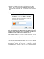
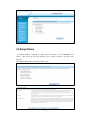
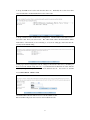
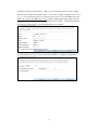
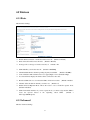
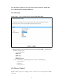
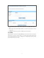
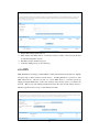
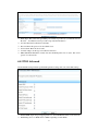
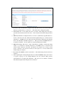
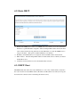
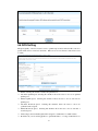
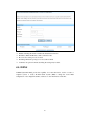
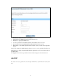
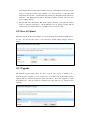
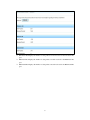
WR300NQ
Wireless Broadband Router
User Guide
Ver. 1.0b
October 2011
1
Contents
Included Items ................................................................................................................................... 4
Chapter 1: User's Guide .................................................................................................................... 5
1.1 Purpose ................................................................................................................................ 5
1.2 User's Guide Overview ....................................................................................................... 5
Chapter 2: Overview ......................................................................................................................... 6
2.1 Introduction ......................................................................................................................... 6
2.2 Features and Specifications ................................................................................................. 6
2.2.1 Features .................................................................................................................... 6
2.2.2 Product Specifications.............................................................................................. 7
Chapter 3: Hardware Installation ...................................................................................................... 8
3.1 Panel Layout ....................................................................................................................... 8
3.1.1 Panel Layout ............................................................................................................ 8
3.1.2 Rear Panel ................................................................................................................ 8
3.2 System Requirements .......................................................................................................... 9
3.3 Installation Environment ..................................................................................................... 9
3.4 Hardware Installation Procedure ......................................................................................... 9
3.4.1 Wired Network Installation ...................................................................................... 9
3.4.2 Wireless Network Installation ................................................................................ 10
Chapter 4: Configuration Guide ...................................................................................................... 10
4.1 Access the Configuration Menu ........................................................................................ 10
4.2 Setup Wizard ..................................................................................................................... 12
4.3 Wireless ............................................................................................................................. 15
4.3.1 Basic ....................................................................................................................... 15
4.3.2 Advanced ................................................................................................................ 15
4.3.3 Security .................................................................................................................. 17
4.3.4 Access Control ....................................................................................................... 17
4.3.5 WDS ....................................................................................................................... 18
4.3.6 WPS ....................................................................................................................... 19
4.3.7 Site Survey ............................................................................................................. 20
4.4 WAN Setting ..................................................................................................................... 20
4.4.1 Basic ....................................................................................................................... 20
4.4.2 WAN Advanced ...................................................................................................... 21
4.4.3 Upload/Download Bandwidth ................................................................................ 22
4.5 LAN .................................................................................................................................. 22
4.5.1 LAN ....................................................................................................................... 22
4.5.2 Static DHCP ........................................................................................................... 24
4.5.3 DHCP Client .......................................................................................................... 24
4.7 Security ............................................................................................................................. 26
4.7.1 Port filter ................................................................................................................ 26
4.7.2 MAC filter .............................................................................................................. 27
2
4.7.3 IP filter ................................................................................................................... 27
4.7.4 URL filter ............................................................................................................... 28
4.7.5 Firewall .................................................................................................................. 28
4.8 Service............................................................................................................................... 29
4.8.1 DMZ ....................................................................................................................... 29
4.8.2 Virtual Server ......................................................................................................... 29
4.8.3 DDNS ..................................................................................................................... 30
4.8.4 NTP ........................................................................................................................ 31
4.9 Management ...................................................................................................................... 32
4.9.1 System Mode.......................................................................................................... 32
4.9.2 Save & Upload ....................................................................................................... 33
4.9.3 Upgrade .................................................................................................................. 33
4.9.4 Password ................................................................................................................ 34
4.9.5 Reboot .................................................................................................................... 34
4.9.6 System Log ............................................................................................................ 34
5.0 Status ................................................................................................................................. 35
5.1.1 System Status ......................................................................................................... 35
5.1.2 Statistics ................................................................................................................. 36
Chapter 6: Wireless Overview ........................................................................................................ 38
6.1 ReadyNet WLAN Information .......................................................................................... 38
6.2 What is a Wireless Network .............................................................................................. 38
6.3 How does a wireless network work? ................................................................................. 38
Chapter 7: Frequently Asked Questions.......................................................................................... 39
3
Included Items
Carefully open the box and remove the contents. Your ReadyNet WR300NQ Wireless Router
should include the following items:
1111-
WR300NQ wireless router
External power adapter
Ethernet cable
Quick start guide
Note: If the product is found to be damaged or if any of the listed parts are missing, please contact
the dealer where the product was purchased.
4
Chapter 1: User's Guide
Thank you for purchasing the ReadyNet WR300NQ Wireless Broadband Router! The
WR300NQ router is designed for SOHO (small office and home office) use and provides many of
the features and functions you expect in a mainstream broadband router. The router features
network security defense and filtering capabilities allowing you greater security and safety within
your SOHO network. The router provides the latest encryption and other security mechanisms
including WPA2. WPS allows you to connect to wireless devices more conveniently with the
push of a button. The WR300NQ router provides an enjoyable internet experience while
providing the peace of mind of having a secure product. The WR300NQ router functions as a
wireless AP (access point) using the IEEE 802.11n standard, but it is also backwards compatible
with 802.11b and 802.11g. The WR300NQ router supports a 802.11n 2T2R dual stream
connection allowing combined data rate up to 300Mbps. The WR300NQ Wireless Router
features a Quick Setup Wizard that helps you quickly configure the router for operation.
Advanced menus provide manual setup of advanced settings for those requiring a more complex
configuration. Before setting up your new WR300NQ Wireless Router, please read this manual
carefully to help you understand the features and functions of this product.
1.1 Purpose
The purpose of this manual is to help you become familiar with and the proper setup and use
of your WR300NQ Wireless Router.
1.2 User's Guide Overview
Chapter I: Introduction: An introduction to the WR300NQ router.
Chapter II: Product Overview: A description of the main features and specifications of the router.
Chapter III: Hardware installation: Provides a guide for the router hardware installation.
Chapter IV: Configuration Guide: Assist with configuring the router's basic network parameters
and advanced features.
5
Chapter 2: Overview
Thank you for purchasing the WR300NQ Wireless Router. This manual will assist you with
the installation and use this product.
2.1 Introduction
WR300NQ Wireless Broadband Router features an integrated firewall, router, wired and
wireless network connectivity. The wireless features are based on the IEEE 802.11n standard.
The WR300NQ router can extend your wireless network range and provide stable connection rates
up to 150Mbps. It is also backwards compatible with the IEEE 802.11b and IEEE 802.11g
standards. Multiple encryption mechanisms help ensure secure data transmission in your
wireless network. A powerful firewall provides security against threats from outside networks
and helps prevent viruses. Menu driven settings allow for quick network setup to provide:
high-speed computer and Internet connection, file transfer, printer sharing, video and audio
streaming, gaming and other communications services.
2.2 Features and Specifications
2.2.1 Features
Meets the IEEE 802.11n, IEEE 802.11g, IEEE 802.11b, IEEE 802.3, IEEE 802.3u standards.
Supports CSMA / CA, CSMA / CD, TCP / IP, PPPoE, DHCP, ICMP, and NAT protocols.
Provides one WAN port, four LAN ports: 10/100M self-adaptive, and automatic rollover
support.
Router is both accessible via wireless and hard wired cabling.
Supports transmission rates up to 150Mbps.
Offers three operating modes: Bridging Mode, Gateway Mode and Wireless ISP Mode.
Supports Quality of Service (QoS)-802.11e, WMM (Wi-Fi Multimedia).
Support WDS (Wireless Distribution Service) repeater functionality allowing for wireless
network expansion.
Support NAT / NAPT IP Sharing, Wide Area Network support: PPPoE / Static IP / DHCP.
Supports virtual server, DMZ host.
Supports WPS push-button encryption.
Supports the latest 64/128-bit WEP, WPA-PSK, WPA2-PSK wireless security standards.
Supports UPnP and DDNS functions.
Built-in DHCP server and built-in firewall.
Provides system security log and traffic statistics.
Remote Web management and configuration in Chinese and English.
Provides a Web management page with a factory settings reset option.
External power adapter.
6
2.2.2 Product Specifications
Model
WR300NQ
Supported standards and protocols
IEEE 802.11n, IEEE 802.11g, IEEE 802.11b,
IEEE 802.3, IEEE 802.3u, CSMA/CA,
CSMA/CD, TCP/IP, DHCP, ICMP, NAT, PPPoE
Port
WAN
1- 10/100M Adaptive RJ45 Port
LAN
4- 10/100M Auto-Negotiation RJ45 Ports
Frequency range
2.4 ~ 2.4835 GHz
11n: 150/270/243/216/162/108/81/54/27 Mbps
135/121.5/108/81/54/40.5/27/13.5 Mbps
130/117/104/78/52/39/26/13 Mbps
65/58.5/52/39/26/19.5/13/6.5 Mbps
Transmission rate
IEEE 802.11g: 54/48/36/24/18/12/9/6 Mbps
(adaptive)
IEEE 802.11b: 11/5.5/2/1 Mbps (adaptive)
Number of working channels
11
Spread Spectrum Technology
DSSS (Direct Sequence Spread Spectrum)
Data modulation
DBPSK, DQPSK, CCK and FDM
(BPSK/QPSK/16-QAM/64-QAM)
:
;
150M -68dBm@10% PER 150M
Wireless
Parameters
:
;
-68dBm@10% PER
:
; :
:
;6M:-88dBm@10%
:
;
108M -68dBm@10% PER 54M -68dBm@10%
Sensitivity @ PER
(packet error rate)
PER
11M -85dBm@8% PER
PER
1M -90dBm@8% PER (Typical)
Transmission distance
(approximate)
Interior up to 120 meters
Outdoors up to 360 meters
(varies depending on router placement)
RF power
16 dBm EIRP
Antenna
2- 5 dBi high-gain omnidirectional fixed antennas
10 Base-T: 3 Class 3 and above, or UTP 100
Base-TX: class 5 UTP
Network Media
LED
indication
WAN
Link / Activity (Connection)
LAN
Link / Activity (Connection)
7
Other
Power, WPS
Dimensions (L × W × H) (mm)
168 x 117 x 33 (mm)
Chapter 3: Hardware Installation
3.1 Panel Layout
3.1.1 Panel Layout
LED Indicators
Name
Power LED
SYS LED
WLAN LED
WPS LED
WAN / LAN LED’s
Link/Activity
Action
Description
Off
No electric power
On (Solid)
Router is powered
Off
Faulty
On (Flashing)
Router Working properly
Off
Wireless functionality not enabled
On (Solid or Flashing)
Wireless is enabled
On (Flashing)
WPS search initiated
Off
WPS normal operation
Off
Port is not connected equipment
On (Solid)
Port is connected to a device
On (Flashing)
Port is receiving and sending data
3.1.2 Rear Panel
1) Power (power jack): This jack connects to the included power supply.
Note: You must use the supplied power supply; if you use a different power supply you may
permanently damage the router.
2) 1- WAN Port (RJ-45): The WAN port connects to your Cable modem, xDSL modem, or
another Ethernet connection that provides your Internet service. Connection is made using
a standard Ethernet cable.
3) 4- LAN Ports (RJ-45): The LAN ports can be used where a wired Ethernet connection is
possible. The LAN ports can connect to an Ethernet hub, switch or other Ethernet enabled
device on the network.
4) Reset Button: If you have password protected your router and have forgotten the password,
or if you would like to set your router back to the factory defaults; press and hold the reset
button for about 8 seconds. The SYS light will go off, the system will re- restart, and the
8
5)
6)
system will be configured with the factory default settings.*
WPS button: Selects WPS setup mode when adding a WPS enabled device to your wireless
network. When adding WPS enabled devices to your network, you can use this push button
and the push button on the WPS enabled wireless device to link them together and provide a
secure connection.
Antenna Interface: Two high-gain omnidirectional antennas are provided. The antennas are
permanently connected to the case of the wireless router and cannot be removed without
damage to the router.
*-Note: After resetting the router, make sure the router fully re-boots before turning off the
power, otherwise the router might not reconfigure to the factory default settings.
3.2 System Requirements
Broadband Internet service: xDSL Modem, Cable Modem, Fiber Optic Modem, Ethernet, etc.
Personal computer to configure the router. During router configuration this computer must be
connected to a router LAN port using an Ethernet cable.
TCP / IP networking software (Windows 95/98/Me/NT/2000/XP/VISTA/7 or other)
Internet Explorer 5.0 or newer.
3.3 Installation Environment
Installation environment requirements:
Place the router horizontally on a flat surface.
Adjust the antennas to point in the vertical direction.
Avoid placing the router near heaters or other heat producing devices.
Do not place the router in dirty or damp locations.
Routers recommended environment:
Ambient Room Temperature: 10° to 40° Centigrade
Humidity: 5% to 90% Relative Humidity (Non-condensing)
3.4 Hardware Installation Procedure
3.4.1 Wired Network Installation
The following procedure will assist with setup of one to four wired network connections:
1) Establish a LAN connection: Connect one end of a network cable to one of the four router
LAN port’s and connect the other end of the network cable to an Ethernet hub, Ethernet
switch or directly to the LAN port of a computer.
9
2)
3)
4)
Repeat step 1 for up an additional three LAN connections.
Establish a WAN connection: Connect one end of a network cable to the router WAN port,
connect the other end of the network cable to an xDSL Modem, Cable Modem, Fiber Optic
Modem or Ethernet WAN system.
Provide power to the router: Connect the barrel connector on the power supply cord to the
back of the router. Plug the power supply into a functional electrical outlet. The router
should start up automatically after about 30 seconds.
3.4.2 Wireless Network Installation
The following procedure will assist with setup of one or more wireless network connections:
1) Establish a WAN connection: Connect one end of a network cable to the router WAN port,
connect the other end of the network cable to an xDSL Modem, Cable Modem, Fiber Optic
Modem or Ethernet WAN system.
2) Provide power to the router: Connect the barrel connector of the power supply to the back of
the router. Plug the wall outlet into a functional electrical outlet. The router should start up
automatically.
3) Connect a personal computer directly to one of the router LAN ports using an Ethernet cable.
the router
5) Configure the router following the steps given in chapter 4. Make sure you assign a SSID,
set up the security and assign a password. You will need the SSID and password to add
wireless devices to the wireless network.
6) After configuring the router it should now be ready to add wireless devices to the network.
7) Go to each 802.11x enabled PC or internet appliance, set the wireless settings using the user
guide for each product. You will need to select the proper SSID name from the list of
available routers, and then enter the wireless password you set up in the router.
8) Repeat the previous step for each additional wireless device you wish to add to the network.
Chapter 4: Configuration Guide
4.1 Access the Configuration Menu
Connect a personal computer directly to one of the four LAN ports of the router using an
Ethernet cable.
Run Internet Explorer (
) or other internet browser software on the PC.
You can gain direct access to the router configuration menu by entering the following IP
address in the internet browser and press return: http:// 192.168.1.1.
10
192.168.1.1 is the default router IP address.
Users will see the following login page where a User Name and Password box will be
displayed. Enter the user name and password (The WR300NQ default user name and
password are "admin"), click the "OK" button. You will then enter the router configuration
menu.
Note: If you changed the WR300NQ's default IP address, you will need to use the new IP
address you chose in order to access the WEB management interface.
Note: The router's default username and password are set to “admin” at the factory.
You can change the default username and password in the router settings page. If you have
forgotten your username and password, you can use the reset button to restore the router to
the original factory settings, including the default user name and password.
If after entering the router IP address in your internet browser and pressing “return”, ensure that
your Ethernet cable is connected directly between your PC and one of the four LAN ports of the
router. Make sure the router has been powered on for at least 30 seconds. Make sure you use
the proper IP address in your web browser to access the router. The router default IP address is
192.168.1.1.
After a successful login the main menu will be shown on the left of the page. The menu
contains the following menu items
:Setup Wizard, Wireless, WAN Setting, LAN, Security,
Service, Management, and Status. You may choose any of the menu items to access the
associated sub-menu items. Within each sub-menu you can set up the corresponding functions.
More detail regarding the various menu items is given below.
11
4.2 Setup Wizard
For Quick and Easy configuration a setup wizard is provided to set the WR300NQ basic
settings. This should provide basic Internet access, wireless encryption and other basic
functions:
Setup Wizard: Wireless Network Setup welcome screen.
1 Choose the type of wireless router work you require. The most common will be”Gateway”.
12
2. Set up the NTP server location and select the time zone. Preferably choose the closest time
server and the time zone that matches the location of the router.
3. Set up a wireless router's LAN interface configuration. The IP address is the address used to
access the router from your web browser. The subnet mask address should match the subnet
mask address of the network you are connecting to, or if you are setting up a new home network,
you may use the default setting.
4. This page is used to configure the network settings for the network connected to your WAN port.
In most cases the default setting will work, or your Internet Service Provider can assist with the
necessary changes to these options in order to work with their network. You can choose: static IP
,
access, DHCP, PPPoE PPTP or L2TP.
User Name: This is the user name for access to the broadband account.
Password: This is the password for access to the broadband account.
13
5. The basic wireless parameter settings. Here you can customize the 802.11x wireless settings.
First time users should use the default settings. You can choose which of the 802.11 bands to use,
b, g, n. You can alter the router mode of operation and you can set your own SSID for the router.
Make sure you know the SSID for the router as it will be required when adding wireless devices to
your network. The radio channel width and sideband can be modified. If the default channel is
heavily used, you may wish to try another channel that is less congested.
6. Set up wireless router encryption. You can select the type of encryption you wish to use to
prevent unauthorized access to your network. Select “Finished” to complete the setup wizard.
14
4.3 Wireless
4.3.1 Basic
Wireless Basic Settings
Disable Wireless: Disable or enable the wireless network. (Enabled = Default)
Mode: Select the wireless network mode. (Default = B+G+N)
Use Type: Choose the type of wireless network job
SSID: Identifies you wireless network.
Channel Width: Wireless channel operating frequency bandwidth. (Default = 40 MHz)
Control Sideband: The sideband can be set to upper (High) or lower. (Default = High)
Associated Clients: Display the wireless clients connected to the router.
Broadcast SSID: Choose to broadcast the SSID, or hide it from others. (Default = Enabled
Channel: Select the 802.11x channel you wish to use. (Default = 9)
Enable Universal Repeater Mode: Allows the router to act as an 802.11x repeater mode.
(Default = Disabled)
SSID of Extended Interface: If you use repeater mode, you must assign another SSID to
access the repeater instead of the originating routers SSID.
(Default =
802.11bgn-SSID-Repeater)
(Default = AP)
(Default = WR300NQ)
4.3.2 Advanced
Wireless Advanced Settings
15
)
Fragment Threshold: Specifies the data packet fragmentation size threshold. When the data
packet is longer than the fragmentation size threshold, the packet will automatically be
divided into multiple packets. Small packets can cause poor network performance, so this
value should not be set too low. Small packets are only beneficial if periodic interference is
causing interference with larger packet sizes.
RTS Threshold: Specifies the data packet RTS (Request to Send) threshold. When the
packet length exceeds this value, the router will send an RTS to the destination site, and then
negotiates to receive the RTS frame. The wireless station responds with a CTS (Clear to
Send) frame to respond to the router.
Beacon Interval: Increasing the Beacon interval can increase the wireless network
performance. If you set the client-side beacon interval to a lower value (more frequent) you
can speed up the wireless client connection speed in a number of online and roaming
environments (such as public hotspots). Beacon units are usually in millisecond’s (1 / 1000
second), the default value is 100 ms.
Preamble Type: The router default uses a long preamble. This prevents the system from
being compatible with legacy IEEE802.11 systems operating at speeds of 1 and 2 Mbps.
IAPP (Inter-Access Point Protocol): When the terminal using IEEE 802.11 wireless LAN is
roaming between access points, this protocol helps assist the transfer between access points
and assists with load balancing.
Protection: Conducive to the slower 11 b/g wireless clients. A complex variety of modes
can successfully connect to the 11n wireless network. The default is "Disabled."
Aggregation: Enhances the local area network to ensure the correct destination of the packet
mechanism.
Short GL: Can help to achieve high throughput, but it will affect backwards compatibility
and system security.
RF Output Power: If your wireless clients are placed close to your router, you can reduce the
transmit power to reduce interference with nearby systems and enhance security.
16
Note: The Advanced settings are part of the advanced wireless parameters, default values
are recommended unless you understand their use.
4.3.3 Security
Security settings.
You can select the encryption method (WEP, WPA, WPA2).
SSID: Select the SSID, for which you want to set the security method.
Encryption method: Sets the encryption mode for the corresponding SSID. You may choose
from the following options:
1 no encryption mode
2.WEP mode.
3.WPA mode.
4.WPA2 mode.
5.WPA-Mixed mode
802.11x Authentication: Enabling authentication allows for RADUIS setup.
o RADIUS IP Address
o RADIUS Port
o RADIUS Password
4.3.4 Access Control
Provides wireless policy access settings to allow or deny access to devices placed in a MAC
address list.
17
Control Mode: Provides the ability to allow or deny access to each MAC address added to a
list.
MAC address: Allows individual MAC addresses to be added to the list with the associated
control mode.
Comment: A comment may be added to each MAC address entry in the list.
4.3.5 WDS
Wireless Distribution System allows multiple IEEE 802.11 network Access Points to interconnect
with each other. It allows a wireless network to be extended without adding additional hard
wired connections between access points. This allows for a scalable wireless network providing
greater transmission range and coverage.
18
Enable WDS: Enables WDS function.
MAC Address: The MAC address of each Access Point you with to add to the network must
be entered individually to this list.
Data Rate: Sets the transmission speed.
Comment: Adding strategy to the current logo.
4.3.6 WPS
WPS (Wi-Fi Protected Setup) is a Wi-Fi Alliance security standard and was introduced to simplify
encrypted setup of 802.11 wireless network devices. A WPS push-button is provided on each
WPS enabled device. The user can add one or more WPS devices to a wireless network by
simply pressing the WPS button on the router and then on the wireless device to be added to the
network. This process will exchange information between the router and the wireless device to
link them together and also sets up a secure link between them.
19
Disable WPS: Allows the WPS function to be turned on and off.
WPS Status: Displays the current status of the WPS function including: SSID, authentication,
encryption type, the AP's PIN code and other information.
PBC mode: PBC (Push Button Configuration) mode can be initiated in two ways, you can
directly press the WPS push-button on the hardware, or select it within the software by
selecting “Start PBC”. Once you have activated the WPS push-button on the router, simply
push the WPS push button the wireless client to automatically connect to wireless AP.
Client PIN: Some devices such as a wireless access card or other wireless client may require
the AP to have a copy of its PIN to provide secure access. The menu provides an option to
enter a PIN code and click “Start PIN”. The WPS will begin to send signals to the client for
whom the PIN was entered and the client will automatically connect to the wireless AP.
4.3.7 Site Survey
Performing a site survey displays a list of wireless connected to the wireless AP (router). The
survey includes information for each connected device including: SSID, BSSID (MAC address),
Channel, Type of operation, Encryption type and Signal Strength.
Refresh Scan: Runs a scan for all devices within range of the AP (router) and provides
information on each of them.
Connect: Allows manual connection to a particular wireless client or IBSS chosen from the
Site Survey list.
4.4 WAN Setting[SA1]
4.4.1 Basic
This menu provides parameter settings for the router WAN port. In most cases the WAN port
connects to a DSL modem, cable modem, or other form of internet service device. Information
for these settings are usually provided by your internet service provider.
20
WAN Type: This selects the type WAN port connection provided by your Internet Service
Provider. Your Internet service provider can provide this information.
Account: Enter the broadband account name.
Password: Enter the password for broadband access.
Service Name: Enter the server name.
Connection Type: Set the type of broadband connection.
MTU (Maximum Transmission Unit): Sets the maximum packet size, in bytes, that can be
passed on to the network.
4.4.2 WAN Advanced
Advanced WAN settings include specific WAN parameter settings and some of the VPN settings.
Enable UPNP: Opens the port mapping function to allow UPnP functionality on the network.
Enable Ping Access on WAN: Allows a PING originating from the WAN.
21
Enable WEB Server Access on WAN: Allows web server access from outside the local
network.
Enable IGMP proxy: The IGMP Proxy is used to monitor IGMP traffic between hosts and
routers. By creating a multicast routing table, the IGMP proxy can improve the efficiency
of network traffic.
Enable PPTP pass through: Allows PPTP packets to pass from the router to the WAN.
Enable IPsec Pass through: IP Sec allows packets to pass from the router from the WAN.
Enable L2TP pass through: Allows L2TP packets to pass from the router to the WAN.
Port loopback: Loop is used mainly used in IP management with some of the procedures,
such as IPSEC tunnel because you need a combined ID or IP, routing.
NAT Fast Forward: Quickly to the private address of the "internal" network through the
router's IP address into a valid forwarding to the outside.
4.4.3 Upload/Download Bandwidth
Here you can display the traffic status of the wireless router.
4.5 LAN
4.5.1 LAN
Configure the LAN (Local Area Network) parameters. These affect both the 4-Ethernet ports
and the wireless clients accessing the router. The LAN settings include: IP address, subnet mask,,
DHCP range and other advanced options.
22
IP Address: This is the IP address assigned to the router that is used to access it from the LAN.
The factory default address is: 192.168.1.1. The address may be changed if required.
Subnet Mask: One or more subnets may exist on a LAN. This setting allows the user to
select the desired subnet mask for the router. In most situations the default setting should be
ok.
DHCP: Dynamic Host Configuration Protocol is used to dynamically assign IP addresses to
devices connected to the router, either hard wired through the LAN ports, or wireless devices
using 802.11. If DHCP is not used, then each wired and wireless client in the network must
have a static IP address manually assigned to it. This option allows the DHCP function to
be enabled or disabled. In most situations you will want this function enabled.
DHCP Client Range: This allows a range of IP addresses, including a starting and ending
address, to be allotted for automatic allocation by the DHCP server to both wired and
wireless clients connected to the LAN. IP addresses are assigned one at a time as client
devices connected to the network are turned on and request one. In most situations the
default settings are adequate.
Host Name: The DHCP host name is entered here. The default setting should work in most
situations.
802.1d Spanning Tree: The Spanning Tree Protocol defined in IEEE 802.1D provides ensures
a loop-free topology for any bridged Ethernet local area network which prevents
self-circulation by providing path redundancy. This option can be enabled or disabled.
The default setting should be adequate in most situations.
23
4.5.2 Static DHCP
Enable Static DHCP: If you want to use DHCP mode, but you have one or more clients that
must have a specific IP address assigned to them, the unique MAC address from each client
can be entered in this list along with the associated IP address you wish the DHCP server to
assign to the client. This option is enabled when the box is checked.
IP Address: List the IP address to be assigned to the device MAC address entered below.
MAC Address: Enter the unique MAC address from the client device for which you entered
the IP address above.
Comment: You may list the reason for the manual address selection.
4.5.3 DHCP Client
The DHCP client table allows the router administrator to view a list of all the clients connected to
the router and the associated MAC address, IP address and IP address lease time (how long the
device has been connected to the router during the current session).
24
4.6 QOS Setting
The QOS (Quality of Service) feature is used to optimize upload and download traffic control for
specific client devices connected to the LAN. Rules are set for one client at a time and are saved
to a table.
Enable: Selecting this checkbox enables the QOS function.
Automatic Uplink Speed: Selecting this checkbox allows the router to choose an optimum
uplink speed.
Manual Uplink Speed: Selecting this checkbox allows the user to choose and enter an
uplink speed.
Automatic Download Speed: Selecting this checkbox allows the router to choose an
optimum download speed.
Manual Download Speed: Selecting this checkbox allows the user to choose and enter a
download speed.
Address Type: Selects whether QOS will be assigned to an IP address or a MAC address.
IP Address: If you are selecting QOS for a specific IP address, or a range of IP addresses on
25
the LAN, enter the beginning and ending IP addresses here. Each client device on the LAN
within the entered address range will have QOS applied with the associated rules.
MAC Address: If QOS is to be applied to a specific device with a known MAC addresses, the
MAC address can be entered here. This method may be asier to use if you cannot set a
static IP address in your client device.
Mode: Select the bandwidth control mode you wish to use: Gauranteed Minimum Bandwidth
or Restricted Maximum Bandwidth.
Uplink Bandwidth: Sets the upload bandwidth.
Downlink Bandwidth: Sets download bandwidth.
Comment: An optional comment describing the settings may be added.
4.7 Security
4.7.1 Port filter
Enable: Selecting this checkbox enables the Port Filter function.
Port Range: Enter the range of ports you wish to block.
Protocol: Selects the protocols to apply the filter to.
Comment: An optional comment describing the settings may be added.
26
4.7.2 MAC filter
Enable: Selecting this checkbox enables the MAC Filter function.
MAC Address: Enter a MAC address you wish to restrict from your network. You may enter
multiple addresses and save them one at a time.
Comment: An optional comment describing the settings may be added.
4.7.3 IP filter
Enable: Selecting this checkbox enables the IP Filter function.
IP Address: Enter an IP address you wish to restrict from your network. You may enter
multiple addresses and save them one at a time.
Protocol: Selects the protocols to apply the filter to.
Comment: An optional comment describing the settings may be added.
27
4.7.4 URL filter
Enable: Selecting this checkbox enables the URL Filter function.
URL: Enter an Internet address you wish to restrict from your network. You may enter
multiple addresses and save them one at a time. Example: sample.com, will not only block
www.sample.com, it will also block access to other domains of sample.com.
4.7.5 Firewall
Firewall: Most of the firewall settings prevent certain types of attacks on the network. It
may be left disabled (default setting) unless a greater level of security is desired. It is not
recommended that you implement any of the Firewall options without an understanding of
what they do and how they might affect normal network operation.
28
4.8 Service
4.8.1 DMZ
After setting the LAN DMZ (De Militarized Zone) host, the host will be fully exposed to the
WAN (Wide Area Network). This can provide unlimited two-way communication between the
LAN and WAN, usually for Web, FTP and mail servers. Just enter the LAN DMZ host IP
address, select “Enable DMZ” and click “Save”. Adding to the DMZ clients may give the local
network to bring insecurity, so Do not use this option.
Enable: Selecting this checkbox enables the DMZ function.
DMZ Address: Enter the DMZ host IP address. This provides unlimited access between the
computer on the local area network and the wide area network. This leaves the DMZ IP
address completely exposed to the WAN.
4.8.2 Virtual Server
Virtual hosting can allow remote LAN users to be automatically shifted to the local server. This
allows the use of a public IP address or FTP to access web services.
You can define a virtual server service port for external network services. All requests to this
port will be redirected to the designated router LAN server (specified by IP address), so users
outside of the network can successfully access the LAN server without affecting the internal LAN
network security.
29
Enable: Selecting this checkbox enables the Virtual Server function.
IP Address: Enter the IP address, such as 192.168.1.103.
Protocol: Choose the protocol to be used.
Port Range: Enter the port range to be used, such as 80-80.
Comment: An optional comment describing the settings may be added.
4.8.3 DDNS
A DDNS (Dynamic DNS) provides the capability for a networked device, such as a router or
computer system, to notify a Domain Name System (DNS) to change the active DNS
configuration of its configured hostnames, addresses or other information, in real time.
30
DDNS Status: Displays the status of your DDNS.
Enable: Enables the DDNS (Dynamic Domain Name Service).
DDNS Server: Specify the DDNS server.
Account: Login Name for the DDNS (Dynamic Domain Name Service) account.
Password: Password for the DDNS (Dynamic Domain Name Service) account.
DDNS: Name of the DDNS (Dynamic Domain Name Service) domain name registration
website.
Note: Before using the DDNS function, first go to the service providers listed in the
drop-down box to apply a dynamic DNS address registration services, and ensure that the
account is active.
Port mapping can work in this port within the network can be mapped to the external network.
4.8.4 NTP
The router can access a public time server through the Internet to synchronize the router system
time.
31
Current Time: The current router clock time.
Time Zone: Select your local time zone.
NTP Server: Select the NTP time server to use. Try to select the server closet to your
location.
4.9 Management
4.9.1 System Mode
System mode selection: You can choose gateway mode, bridge mode and wireless ISP mode.
Gateway: Select Gateway mode if you are connecting an ADSL, Cable, or Optical Modem to
the wide area network (WAN) port for Internet access. In this mode the router can use a
single IP address on the WAN provided by the Internet service provider, and share it with all
of the Internet enabled devices al area network (LAN) of all PC users a way to NAT on the
WAN port to share a unique IP address.
Bridge: Select Bridge mode if you want to bridge client devices connected to the 4-Ethernet
32
ports with the clients using the 802.11 wireless network. This might be used where you are
trying to extend the wireless range capability on a network where a router with NAT
functionality already exists. The IP addressing will just pass through the bridge without any
translation. The NAT (Network Address Translation) function, firewall, and some other
services will be disabled.
Wireless ISP: Select the Wireless ISP (Internet Service Provider) mode when the internet
service is delivered using 802.11. All the Ethernet ports are bridged together with the
wireless acting as a client connected to your ISP's service access point (AP).
4.9.2 Save & Upload
This menu page allows the router settings to be saved for backup and loaded from backup for easy
recovery. You also have the option to restore the factory default settings using the “Factory”
button.
4.9.3 Upgrade
The firmware upgrade feature allows the user to load the latest version of firmware. If a
firmware update is available, you can download it to a computer from the ReadyNet website.
Click the "Browse" button then select the update file location. Next click "Upgrade" to install
the firmware file. Once the update has completed, the router will re-boot to initiate the new
firmware.
33
4.9.4 Password
This menu page is used to set a login name and password to access the router configuration menu.
Be sure to change your default password to minimize the possibility of an unauthorized person
accessing the configuration menu.
Account: Enter a user name of your choice. (Default = “admin”, but box will be blank)
Password: Enter a password of your choice. (Default = “admin”, but box will be blank)
Confirm Password: Re-enter the password for verification.
4.9.5 Reboot
When changes are made to some system configuration settings, you may need to restart the system
in order to activate the changes that were made. Note: The boot start-up time is less than a
minute, please be patient.
4.9.6 System Log
The system log can store and display network events that are tracked by the router. A remote
log-server can also be set up.
34
Enable Log: Select the checkbox to enable the System Log feature.
Log Server IP Address: Enter the log server IP address.
5.0 Status
5.1.1 System Status
Displays the WR300NQ system status as shown below.
35
System Status: This box displays the system uptime, firmware version, kernel version,
configuration file version and the build time.
LAN Configuration: This box displays the router LAN IP address, LAN subnet mask, LAN
default gateway, the DHCP server status and MAC address of the LAN.
WAN Configuration: This box displays the connection type; the WAN IP address, WAN
subnet mask, WAN default gateway and WAN MAC address.
WLAN Configuration: This box displays the WLAN mode, 802.11 communication type, the
SSID, the channel, encryption status, BSSID and associated clients.
5.1.2 Statistics
The WR300NQ router maintains statistical information since the last start-up. An example is
shown below.
36
Wireless LAN: Displays the number of data packets sent and received for the wireless LAN
port.
Ethernet LAN: Displays the number of data packets sent and received for the Ethernet LAN
port.
Ethernet WAN: Displays the number of data packets sent and received for the Ethernet WAN
port.
37
Chapter 6: Wireless Overview
6.1 ReadyNet WLAN Information
READYNET wireless products are based on industry standards for your home, business or
public access wireless network. They provide simple, compatible, high-speed wireless
connection. By strictly adhering to the 802.11 IEEE standards, READYNET wireless products
will allow you to access secure data in your home or small business, when and where you want.
You will be able to enjoy the freedom of a wireless network!
WLAN (Wireless LAN) or Wi-Fi uses a wireless signal, rather than copper wires, to transmit
and receive data in computerized networks. Wireless LAN has become very popular and is
found in many homes, small offices, airports, coffee shops, universities and other public places.
Innovative implementation of WLAN technology has helped people work and communicate more
efficiently. With computers, multimedia devices and other Internet ready devices becoming
readily available, network connections are needed in many places where hard-wired infrastructure
is not available. WLAN provides an easy method for establishing a wireless network, without
cable connections, and rapid setup that is appealing for Internet Service Provider installers or
home owners and small business owners who want to set up their own network.
Wireless users can use the same network based software applications that are used in wired
network applications. Notebook computers utilize wireless adapter and Ethernet adapter cards
that support the same protocol ensuring compatibility. Network based printers, plotters, and
other hardware are also compatible with WLAN using the same operating system hardware
drivers.
6.2 What is a Wireless Network
Wireless Local Area Networks or WLAN’s carry network information using transmitted radio
waves as a communications medium. They are based on IEEE standards, with the most common
being 802.11b/g/n. Wireless networks perform the same function as wired networks, with the
main difference being transmission media. Wireless networks use radio communications
technology and wired networks utilize copper wire. Networks allow computers and other
network enabled devices to share information with each other.
6.3 How does a wireless network work?
A wireless network consists of two or more computers or network enabled devices that are
configured to communicate using radio waves to transfer data or share resources. A network
within a single building or home is usually called a Local Area Network or LAN. The larger
network connecting multiple homes, businesses and universities is called the internet. The
38
Internet is part of a Wide Area Network or WAN. A device called a MODEM is usually used to
access the WAN using DSL, Cable, Fiber Optic, or a Wireless connection. The modem converts
the incoming WAN signal from the internet to a wired Ethernet connection that can be connected
to a router. A router is a bridge between the WAN and a LAN. A router takes a single
connection to the WAN and by changing the addressing it allows the signals to be routed to
multiple computers and other network devices in the LAN. Most routers provide a single WAN
input, 4-Wired Ethernet ports, and 802.11 wireless capabilities all in one device. Sometimes the
MODEM and router are combined into a single unit.
There are two types of wireless networks:
Easy mode: Devices in the network can communicate directly with each other without the use of a
router or access point. This method can be used to share files and printers, however it is not easy
to connect to the network (wired or wireless). This model is also known as peer to peer
networking.
Infrastructure mode: Each device in the network is assigned an IP address, either manually or by
the router. The router acts as an access point and handles all data transfer and network traffic.
It is easy to connect this type of configuration to a wired network, whether it is the Local Area
Network LAN or the Internet, the Wide Area Network or WAN. For most home and small
business networks, Infrastructure mode is the best choice.
Chapter 7: Frequently Asked Questions
1. Why can’t I enter the WEB management interface?
If you are new to using a router, make sure your computer and the router are connected
together on the same network segment. A network cable should be connected directly between
the computer and one of the four LAN ports on the router. With the computer and router both
powered on, both the link light on the computer LAN interface and on the corresponding router
link light should be lit.
The default router address is: “http://192.168.1.1”. Enter this in the address line of your
web browser and press “Enter”. If you modified the router's default LAN IP address, make sure
you use the new IP address you assigned to access the router. If you forgot your new settings,
you will need to perform a system reset to change the router settings back to the factory default
settings. See the following section on resetting the router. Once the default factory settings are
restored you can use the default router IP address, username and password to access the router
setup menu.
If you are able to get to the login screen but your username and/or password are not
recognized, you will need to perform a system reset to change the router settings back to the
factory default settings. See the following section on resetting the router. Once the default
factory settings are restored, you can use the default router IP address, username and password to
access the router setup menu.
2. How do I reset the router to the factory default settings?
If the network administrator has forgotten the router IP address, username, or password, then
39
the router must be reset to the factory default settings. This will allow the default IP address,
username and password to function again. Once the router is reset and the router menu accessed,
new settings can be applied to the router. Here are the steps for resetting the router:
1. Find the small hole marked “Reset” on the rear panel of the router. The reset button is
recessed in this hole.
2. Disconnect power from the router, and then use a pen or the end of a paper clip to press
the Reset button.
3. Re-connect power to the router while pressing the reset button. Wait about 3-10 seconds
and watch the LED’s on the front panel. The LED’s will blink indicating the reset has
occurred. You may now release the Reset push button.
4. Once the router has been reset, it can be accessed using the following information:
a. Default IP address is “http://192.168.1.1”. In rare cases this may conflict if
your computer is set to the same address.
b. Default user name is “admin”.
c. Default password is “admin”.
3. What is WPA?
WPA (Wi-Fi Protected Access) provides the latest security capabilities available for 802.11
networks. It was meant to replace WEP (Wired Equivalent Privacy) security protocols and
algorithms that are easy to circumvent. WPA can be set up using the WPS function, thus making it
easier for the average user to setup a secure wireless network without having knowledge of the
system. This makes it more likely for security to be used. WPA also prevents packet forgeries
through packet integrity checking.
WPA uses more complex key generation algorithms to generate encryption keys, this makes
it very difficult if not impossible to calculate a common key. WPA also prevents data tampering by
using authentication functions.
4. What is NAT?
NAT (Network Address Translation) is the process of translating an IP address to another IP
address. In the case of a router, usually only a single IP address is provided by your internet
service provider. Each internet enabled device must have its own IP address and an IP address
cannot be shared. In order to allow multiple Internet enabled devices to function within a home
or small office a Network Address Translation is provided by the router. The single IP address
provided by your internet service provider on the WAN, is translated to multiple IP addresses on
your local are network within the home. This hides the local management of IP addresses to the
WAN side of the router which reduces the risk of external network attacks. Each home or small
office can have many non-registered IP addresses, and convert them to a single outside the
registered IP address. This reduces the cost of IP address registration and helps save the current
lack of addresses.
NAT functionality is often integrated into a router, firewall, or stand-alone NAT device.
Popular operating systems and other software (mainly proxy software, such as WINROUTE), also
provide a NAT function. NAT devices or software maintain a state table for the internal network of
private IP addresses that are mapped to the external network IP address. Each packet traveling
40
through the NAT must be translated to the correct IP address.
5. What factors affect the wireless signals?
1. 802.11b/g/n wireless broadband utilizes microwaves for communication. Microwaves
travel best in straight lines between the access point and client antennas. Obstacles such
as walls, persons, furnishings or other items that lie between the access point and client
antennas can reduce and sometimes completely block the microwave transmissions.
Careful placement of the router and client devices so that the antennas have a clear line of
communication is important for reliable wireless connections and adequate transmission
speeds.
2. Physical obstacles, not only block the microwave radio signals, but they can absorb
electromagnetic energy weakening the communication channel. Concrete walls and
floors, metal doors or other metal objects in the home or small office can make the
wireless signals very weak and lead to poor communication or loss of communication
between wireless devices.
3. The IEEE 802.11b/g/n standards share the 2.4 GHz ISM (Industrial Scientific, Medical)
band with other devices that share the same radio frequencies. These devices include:
microwave ovens, Bluetooth devices, cordless phones, commercial and industrial
communication equipment. If any of these devices create a radio signal stronger than
the intended transmitter at the point of reception, then the receiving device will
experience interference and wireless network communication will be affected.
4. If multiple wireless networks are operating in the same vicinity and some of the channels
are shared, there is a high likelihood that interference will occur between the systems that
will reduce the performance of all wireless networks sharing the same channel. You can
scan for a list of current stations and try setting your wireless network to operate on an
unused channel.
5. Other sources of interference may come from: Power-lines, radio towers, welders, electric
train or bus, high-voltage power transformers and other strong source of signal
interference, also may produce a strong wireless signal interference or equipment. The
wireless network devices will work best if kept at least 100 meters from these sources of
interference.
6. Hints on placing wireless networking devices:
a. Try and choose locations that are higher to improve antenna radiation and to reduce the
obstacles that might block the signal. Choose a location for the router that provides the
least obstacles between it and all each of the wireless clients connected to it. If you are
able to have line of sight between them, you will likely have the best possible connection.
b. Try and select a wireless channel that is not in use for the router. This will reduce
interference from nearby networks.
c. Place the router so that cordless phones and other electric appliances are not in close
proximity to the wireless network devices.
d. If the wireless antennas are removable, the communication link can be enhanced by
replacing the antenna with an antenna having higher gain to improve the wireless signal.
41