1
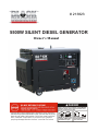
# 213823
5500w silent Diesel generator
Owner’s Manual
DANGER
Using a generator indoors CAN KILL YOU IN MINUTES.
Generator exhaust contains carbon monoxide. This is
a poison you cannot see or smell.
Read carefully before attempting to assemble, install, operate or
maintain the product described. Protect yourself and others by
observing all safety information .Failure to comply with the
user , s manual could result in personal injury and/or
property damage! Retain the user , s manual for future
NEVER use inside a home
or garage, EVEN IF doors
and windows are open.
Only use OUTSIDE and
far away from windows,
doors, and vents.
TABLE OF CONTENTS
1. GENERAL SAFETY…………………………………………………….…………………...1
A. SET UP PRECAUTIONS…………………………………………………………………1
B. OEPRATING PRECAUTIONS…………………………………………………..……….2
C. SERVICE PRECAUTIONS……………………………………………..… .…………… 2
2. UNPACKING…………………………………………………………………………………3
3. CONTROLS…………………………………………………………………………………..4
4. SET UP INSTRUCTIONS……………………………………………………………………5
A.LOCATION………………………………………………………..……………………….5
B. GROUDING………………………………………………………………………………5
5. OPERATING INSTRUCTIONS……………………………………………………………...6
A.START THE ENGINE……………………………………………………………………6
CHECK AND FILLING ENGINE OIL………………………………………………6
CHECK AND FILLING FUEL……………………………………………………….6
BLEED THE FUEL LINE…………………………………………………………….6
CONNECT THE BATTERY……………………………………………… ………7
HOW TO SHUT ENGINE OFF……………………………………………………….7
START PREOCEDURE………………………………………………………………7
TO START THE ENGINE………………………………………………… ………7
BREAK-IN PERIOD………………………………………………………………….8
B. EQUIPMENT OPERATION…………………………………………………………… 8
TO POWER TOOLS AND EQUIPMENT……………………………………………. 8
6. TECHNICAL SPECIFICATION…………………………………………………………… 8
7. SERVICING……………………………………………………………………………………9
A.MAINTENANCE PROCEDURES…………………………………………………… 9
ENGINE OIL CHANGE…………………………………………………………… 9
AIR FILTER ELEMENT MAINTENANCE……………………………………… 9
FUEL FILTER REPLACEMENT……………………………………………………. 9
B.CLEANING, MAINTENANCE, AND LUBRICATION SCHEDULE………………… 10
AFTER INITIAL 20 OPERATION HOUR PERIOD…………………………… 10
EVERY 50 OPERATION HOURS………………………………………………… 10
EVERY 100 OPERATION HOURS……………………………………………………10
EVERY 250 OPERATION HOURS……………………………………………………10
EVERY 500 OPERATION HOURS……………………………………………………10
C. STORAGE………………………………………………………………………………. 10
D. DIESEL FUEL AND MICROBES……………………………………………………… 10
E. TROUBLE SHOOTING………………………………………………………………… 11
8. EXPLODED VIEW AND PARTS LIST…………………………………………………….. 12-16
1. GENERAL SAFETY
Important safety information:
In this manual, on the labeling, and all other information provided with this product:
This is the safety alert symbol. It is used to alert you to potential personal injury hazards.
Obey all safety messages that follow this symbol to avoid possible injury or death.
DANGER indicates a hazardous situation which, if not avoided, will result in death
or serious injury.
WARNING indicates a hazardous situation which, if not avoided, could result in
death or serious injury.
CAUTION, used with the safety alert symbol, indicates a hazardous situation which,
if not avoided, could result in minor or moderate injury.
NOTICE is used to address practices not related to personal injury.
WARNING! Read all instructions. Failure to follow all instructions listed below may
result in fire, serious injury and/or Death. The warnings and precautions discussed in this
manual cannot cover all possible conditions and situations that may occur. It must be
understood by the operator that common sense and caution are factors which cannot be built
into this product, but must be supplied by the operator. Save these instructions.
A. Set up precautions
1. Diesel fuel and fumes are flammable, and potentially explosive. Use proper fuel storage and handling
procedures. Do not store fuel or other flammable materials nearby.
2. Have multiple ABC class fire extinguishers nearby.
3. Operation of this equipment may create sparks that can start fires around dry vegetation. A spark
arrestor may be required. The operator should contact local fire agencies for laws or regulations
relating to fire prevention requirements.
4. Set up and use only on a flat, level, well-ventilated surface.
5. Wear ANSI-approved safety goggles, heavy-duty work gloves, and dust mask/respirator during set
up.
6. Use only oil and fuel recommended in the “Specifications” section of this manual.
B. Operating precautions
1.
Carbon Monoxide Hazard using an engine indoors can Kill You in MINUTES.
Engine exhaust contains carbon monoxide. This is a poison you cannot see or smell. NEVER use inside
a home or garage, EVEN IF doors and windows are open. Only use OUTSIDE and far away from
windows, doors, and vents.
2. Keep children away from the equipment, especially while it is operating.
1
3. Do not leave the equipment unattended when it is running. Turn off the equipment (and remove safety
keys, if available) before leaving the work area.
4. Wear ANSI-approved safety goggles and hearing protection during use.
5. People with pacemakers should consult their physician(s) before use. Electromagnetic fields in close
proximity to a heart pacemaker could cause pacemaker interference or pacemaker failure. Caution is
necessary when near the engine’s magneto or recoil starter.
6. Use only accessories that are recommended by Northern Tool for your model. Accessories that may be
suitable for one piece of equipment may become hazardous when used on another piece of equipment.
7. Do not operate in explosive atmospheres, such as in the presence of flammable liquids, gases, or dust.
Diesel-powered engines may ignite the dust or fumes.
8. Stay alert, watch what you are doing and use common sense when operating this piece of equipment.
Do not use this piece of equipment while tired or under the influence of drugs, alcohol or medication.
9. Do not overreach. Keep proper footing and balance at all times. This enables better control of the
equipment in unexpected situations.
10. Dress properly. Do not wear loose clothing or jewelry. Keep hair, clothing and gloves away from moving
parts. Loose clothes, jewelry or long hair can be caught in moving parts.
11. Parts, especially exhaust system components, get very hot during use. Stay clear of hot parts.
12. Do not cover the engine or equipment during operation.
13. Keep the equipment, engine, and surrounding area clean at all times.
14. Use the equipment, accessories, etc., in accordance with these instructions and in the manner intended
for the particular type of equipment, taking into account the working conditions and the work to be
performed. Use of the equipment for operations different from those intended could result in a
hazardous situation.
15. Do not operate the equipment with known leaks in the engine’s fuel system.
16. This product contains or, when used, produces a chemical known to the State of California to cause
cancer and birth defects or other reproductive harm.
17. When spills of fuel or oil occur, they must be cleaned up immediately. Dispose of fluids and cleaning
materials as per any local, state, or federal codes and regulations. Store oil rags in a bottom-ventilated,
covered, metal container.
18. Keep hands and feet away from moving parts. Do not reach over or across equipment while operating.
19. Before use, check for misalignment or binding of moving parts, breakage of parts, and any other
condition that may affect the equipment’s operation. If damaged, have the equipment serviced
before using. Many accidents are caused by poorly maintained equipment.
20. Use the correct equipment for the application. Do not modify the equipment and do not use the
equipment for a purpose for which it is not intended.
21. Wash hands with soap and water after handling diesel fuel or lubricating oil.
C. Service precautions
1. Before service, maintenance, or cleaning:
a. Turn the engine switch to its “OFF” position.
b. Allow the engine to completely cool.
2. Keep all safety guards in place and in proper working order. Safety guards include mechanical guards,
and heat shields, among other guards.
2
3. Do not alter or adjust any part of the equipment or its engine that is sealed by the manufacturer
or distributor. Only a qualified service technician may adjust parts that may increase or decrease
governed engine speed.
4. Wear ANSI-approved safety goggles, heavy-duty work gloves, and dust mask/respirator during service.
5. All connections from the Generator to the load must be installed by a licensed electrician in compliance
with local, state, and federal laws.
6. The generator must be grounded in accordance with applicable electrical codes and standards before
operation.
7. Insulate all connections and disconnected wires.
8. Do not connect or disconnect load connections while standing in water or on wet ground.
9. Do not overload the generator. Over loading can cause fires in the electrical cords, in addition to
generator and appliance damage.
10. Connect the generator only to a load or electrical system (120 volt or 240 volt) that is compatible with
the electrical characteristics and rated capacities of the generator.
11. Set up the generator outdoors in a well-ventilated, dry area, away from building air intakes. The
generator should be protected from direct exposure to rain and snow. Do not set up the generator on a
conductive surface such as a metal deck.
12. Do not connect generator directly into a home’s electrical lines. Do not plug a generator into an outlet in
the home. Connecting a generator directly to a utility power supply can ‘back feed’ along the power lines
and kill or injure utility workers working on the lines.
13. Do not charge vehicle batteries with this Generator.
14. Maintain labels and nameplates on the equipment. These carry important information. If unreadable or
missing, contact Harbor Freight Tools for a replacement.
15. Have the equipment serviced by a qualified repair person using only identical replacement parts. This
will ensure that the safety of the equipment is maintained. Do not attempt any service or maintenance
procedures not explained in this manual or any procedures that you are uncertain about your ability to
perform safely or correctly.
16. Store equipment out of the reach of children.
17. Follow scheduled engine and equipment maintenance.
18. Refueling Precautions:
a. Do not smoke, or allow sparks, flames, or other sources of ignition around the equipment, especially
when refuelling.
b. Do not refill the fuel tank while the engine is running or hot.
c. Do not fill fuel tank to the top. Leave a little room for fuel expansion.
d. Refuel in a well-ventilated area only.
2. Unpacking
When unpacking, check to make sure that the item is intact and undamaged. If any parts are missing or
broken, please call 1-866-393-3968 as soon as possible.
3
3. Controls
Engine Switch
Power Indicator
Voltage Meter
Circuit Breaker
Fuse Cover
120V&240V receptacle
120V Receptacles
4
12V 8.3A DC
receptacle
4. Set up instructions
Read the entire important safety information section at the beginning of this manual
including all text under subheadings therein before set up or use of this product.
To prevent serious injury from accidental starting: Turn the power switch of
the equipment to its “OFF” position, wait for the engine to cool before assembling or making any
adjustments to the equipment.
To prevent serious injury: Operate only with proper spark arrestor installed.
Operation of this equipment may create sparks that can start fires around dry vegetation. A spark
arrestor may be required. The operator should contact local fire agencies for laws or regulations
relating to fire prevention requirements.
Note: For additional information regarding the parts listed in the following pages, refer to the Assembly
Diagram near the end of this manual.
A. Location
1. The Generator must be installed outdoors where ventilation is readily available.
2. Install the Generator so that the air inlets and outlets are not blocked by obstructions such as bushes,
trees, or snow drifts. Locating it in the path of heavy winds or snowdrifts may require the placement of
a barrier for protection. The air inlet should face the prevailing wind direction.
3. Install the Generator on a concrete slab or other area where water can not reach it.
4. Generator placement should allow four feet of access on all sides for maintenance.
5. Place the Generator as close as possible to the electrical tools and equipment being powered to
reduce the length of extension cords.
B. Grounding
1. Connect a #12 AWG grounding wire (not included) from the Grounding Point on the Generator to a
grounding rod (not included) that has been driven at least 24 inches into the ground. The grounding rod
must be a copper or brass rod which can adequately ground the Generator. Only a trained and
licensed electrician should perform this procedure.
grounding point
2. Electrical and other permits may be required for the installation of emergency power systems.
Investigate local building and electrical codes before installing this unit. Installation must be completed
by a licensed contractor.
5
5. Operating Instructions
Read the entire important safety information section at the beginning of this manual
including all text under subheadings therein before set up or use of this product.
A. Starting the Engine
Inspect engine and equipment looking for damaged, loose, leaking and missing parts
before set up and starting. If any problems are found, do not use equipment until fixed
properly.
Checking and Filling Engine Oil
CAUTION! Your Warranty is VOID if the engine’s crankcase is not properly filled with oil before each use.
Before each use, check the oil level. Do not run the engine with low or no engine oil. Running
the engine with no or low engine oil WILL permanently damage the engine.
1. Open the front panel; remove the dip stick and wipe it off with a clean rag.
2. Reinsert the dipstick completely and remove it to check the oil level. The oil level should be between the
high and low marks on the dipstick.
3. If the oil level is below the low mark on the dipstick add the appropriate type of oil until the oil level is
between the high and the low marks.
Oil type: SAE 5W-40
4. Replace the Oil Dipstick.
5. Wipe off any spilled oil.
CAUTION! Do not run the engine with too little or too much oil. The engine will be permanently damaged.
Checking and Filling Fuel
1. Check the fuel level on the built-in fuel gauge.
Fuel Gauge
Fuel Tank Cap
WARNING! To prevent serious injury from fire: Fill the fuel tank in a well-ventilated area
away from ignition sources. Do not smoke.
2. To fill the Fuel Tank, first wipe off the Fuel Tank Cap and the surrounding area.
3. Unscrew, and remove the Fuel Tank Cap.
4. Fill the Fuel Tank to about 1 inch under the fill neck of the tank with #2 diesel.
5. Then replace the Fuel Tank Cap.
Bleed the fuel line
This is a two man operation. Place rags under the bleeding points to catch flow of fuel.
1. The fuel system should be bled to remove possible trapped air from the system before first use and after
each fuel filter, fuel tank flushing, or general service of the diesel generator. Note: Place rags at the
bleeding points to capture spilled fuel.
2. Turn the fuel valve to the off position. Top off fuel tank with fresh diesel fuel. Slide the hose clamp away
from the fuel pump end. Loosen the hose at the pump to allow fuel to bleed out. Turn the fuel valve to its
open position. Depress the decompression lever and while holding it down crank the engine for a few
seconds at a time. Fuel and trapped air will emerge from the line and as soon as just fuel flows without
traces of air, push the fuel line back onto the intake of the pump and stop cranking the engine. Reattach
the hose clamp. Note: Never crank the engine more than ten seconds at a time. Allow at least one
minute prior to further cranking.
6
3. Using two wrenches, hold the injector with one and back off the steel feed line nut with the other wrench.
Repeat the above mentioned flushing cycle to bleed the air from the injector. Wipe all spilled fuel from
the engine and components. Note: Do not close the fuel valve with the engine running. This may only be
done for the intention of shutting the engine off should the fuel shut-off system fail.
Connect the Battery
The Generator ships with the negative battery cable disconnected. Before the generator can be started the
covering on the battery cable must be removed and the cable must be secured to the negative ground
terminal on the battery. Recheck battery’s positive terminal connection for tightness.
How to Shut Engine Off
A diesel engine is not operated like a gasoline engine. When operating a diesel engine, one should be
aware of various options of how to shut the engine off.
1. Turn the ignition key to the off position.
2. Push down on the fuel shut off lever to release the Control Handle (13).
3. Turn the fuel valve to its “OFF” position.
Start Procedure
Before starting the engine:
a. Follow the Set Up Instructions to prepare the equipment.
b. Inspect the equipment and engine.
c. Fill the engine with the proper amount and type of fuel and oil.
e. Read the Equipment Operation section that follows.
To start the engine:
1. Unplug all loads from the Generator before starting to prevent permanent damage to any appliances or
tools.
2. Depress the Decompression Handle (16) all the way (Cold starting only).
3. Open the front panel and turn the fuel shut-off valve to its “OPEN” position.
4. Rotate the Control Handle (13) to the right until release button on the Right hand side of the Handle
Bracket (12) pops up and locks in place.
5. Insert the engine key into the ignition and turn it to “START” position for up to 10 seconds. Note: To
prolong starter life, use short starting cycles (10 seconds maximum). If the engine does not start, wait
one minute before attempting to start again.
7
Break-in Period
1. Breaking-in the engine will help to ensure proper equipment and engine operation, and will extend the
engine’s lifespan. The warranty is void if the engine is not broken in properly. The first 20 hours of
operation is the break-in period.
2. During the first 3 hours of use:
Do not apply a heavy load to the equipment.
3. After the first 20 hours of use:
Change the engine oil.
Under normal operating conditions subsequent maintenance follows the schedule explained in the
Maintenance AND Service section.
Equipment Operation
To Power Tools and Equipment:
1. Prior to powering tools and equipment, make sure the Generator’s rated wattage capacity (5000 W) is
adequate to supply all electrical loads that the unit will power. If powering exceeds the Generator’s
capacity, it may be necessary to group one or more of the tools and/or equipment for connection to a
separate Generator.
2. Start the Generator with no loads attached. Once the Generator warms up, with the equipment or
tools turned off, connect the Power Cords of the AC tools and equipment into the AC Outlets. Only
connect 120V AC tools to the 120V AC Outlets. Only connect 240V AC NEMA L14-30 type plug tools
the 240V AC Outlet. Do not use this generator to charge DC vehicle batteries. The Generator
has a Circuit Protector to protect the unit in case of an overload. If an overload occurs, the Circuit
Breaker will switch to its “OFF” position and cause the Generator to shut down. The Pilot Light will
shut off to show that the Circuit Protector has been tripped. Disconnect all devices and press the
Circuit Breaker back up to reset the Generator.
3.
When finished using the Generator turn the tools off and unplug them. Allow the Generator to run for
several minutes with no devices connected to allow the temperature to stabilize. Turn the Power
Switch to its “OFF” position. Turn the Fuel Valve to the “OFF” position.
4.
To prevent accidents remove the key and disconnect negative battery terminal after use. Wait for the
engine to cool, clean external parts with clean cloth, then store the equipment out of children’s reach
according to the Storage instructions in this manual. If the Generator is not going to be used again
soon, drain the diesel fuel.
6. Technical Specifications
Engine Type
Bore x Stroke
Compression Ratio
Displacement
Rotation viewed from PTO (power takeoff-the
output shaft )
Fuel
Type
Capacity
Type
Engine Oil
Capacity
Valve
Clearance Intake
(cold)
Exhaust
Speed
Idle
Maximum
Rated Wattage
Maximum Wattage
Run Time @ Full Load
Sound Level
Four stroke single cylinder OHV diesel,
10HP
86 x72mm
19+:1
418cc
Counterclockwise
#0 Diesel Fuel
4.0 Gallons
SAE 20W
1.65L
0.10~0.15mm
0.10~0.15mm
1,100RPM
3,600RPM
5000 Watts
5500 Watts
7 Hour with full tank
96 dB
At high altitudes, the engine’s carburetor, governor, and any other parts that control the fuel-air ratio will
need to be adjusted by a qualified mechanic to allow efficient high-altitude use and to prevent damage to
the engine and any other devices used with this product.
8
7. Servicing
To prevent serious injury from accidental starting: Turn the power switch of
the equipment to its “OFF” position, wait for the engine to cool before performing any inspection,
maintenance, or cleaning procedures.
To prevent serious injury from equipment failure: Do not use damaged
equipment. If abnormal noise, vibration, or excess smoking occurs, have the problem corrected
before further use.
Maintenance Procedures
Many maintenance procedures, including those not detailed in this manual, will need to be
performed by a qualified technician for safety. if you have any doubts about your ability to safely
service the equipment or engine, have a qualified technician service the equipment instead.
Note: Warranty is void if proper maintenance and servicing procedures are not followed.
Engine Oil Change
CAUTION! Oil is very hot during operation and can cause burns. Wait for engine to cool before changing oil.
1. Place a drain pan (not included) underneath the crankcase’s drain plug.
2. Remove the drain plug and empty oil. Recycle used oil.
3. Inspect drain plug gasket for damage or tears. Replace gasket if damaged. Replace the drain plug and
tighten it.
4. Refill the oil to the proper level following the instructions under the Starting the Engine section.
Air Filter element Maintenance
1. Routine maintenance to the air cleaner helps maintain proper airflow to the engine. Service the air
cleaner according to the following steps every 250 or 500 hours, or more often when using the generator
in a dusty area.
2. Wipe off the air cleaner cover.
3. Remove the air cleaner maintenance panel by unscrewing the bolts with 10-mm wrench.
4. Remove the wing nut from the bolt holding the air cleaner cover. Remove the air cleaner cover.
5. Take out the used air cleaner element. Replace with a new element.
6. Reinstall the air cleaner cover, tighten the wing nut, then screw back the air cleaner maintenance panel.
Fuel Filter Replacement
WARNING! To prevent serious injury from fire: Replace the fuel filter in a well-ventilated
area away from ignition sources. Do not smoke.
1. Wait for engine to cool completely before proceeding.
2. Wear protective gear including, ANSI approved safety goggles.
3. Turn the fuel valve to the “off” position.
4. Unscrew the bolt holding the fuel filter to the frame using a 13mm wrench. Pull the fuel valve/filter
assembly out of the enclosure. Place a bucket under the assembly to catch the fuel.
5. Remove the fuel filter cup, and the filter element.
9
6. Clean the cup of all sediment using a rag or brush.
7. Replace the fuel filter element.
8. Reinstall the fuel filter element, fill the cup with fresh and clean diesel fuel and assemble per steps 5 and
4 above.
9. Open the fuel valve until the filter is filled.
10. Remove the hose clamp and slightly remove fuel outlet hose to purge out any trapped air in the line.
Re-attach the hose and clamp.
11. Remove four screws and Injector Inspection Cover (49) from top of Sound Shield Panel (41). Place a
clean rag under the injector inlet and using two wrenches loosen input line nut by one turn. Tap starter
to force fuel out of injector line. When air bubbles stop, re-tighten the input line nut.
Cleaning, Maintenance, and Lubrication Schedule
Note: This maintenance schedule is intended solely as a general guide. If performance decreases or if
equipment operates unusually, check systems immediately. The maintenance needs of each piece
of equipment will differ depending on factors such as duty cycle, temperature, air quality, fuel quality,
and other factors.
Note: These procedures are in addition to the regular checks and maintenance explained as part of the
regular operation of the engine and equipment.
After initial 20 operation hour period:
a. Change engine oil.
Every 50 operation hours:
a. Replace fuel filter.
Every 100 operation Hours:
a. Change engine oil (or with frequent use; every three months).
Note: All maintenance procedures scheduled for 25, 50, and 100 operation hours should be performed at
least yearly.
Every 250 operation Hours:
a. Clean fuel tank.
b. Clean carbon build-up from combustion chamber.
c. Replace the air filter.
Every 500 operation hours:
a. Clean fuel tank and fuel filter.
Storage
1. Wait for engine to cool, then clean engine with clean cloth.
2. When the equipment is to remain idle for longer than 20 days, prepare the engine for storage as follows:
a. Wait for engine to cool.
b. Disconnect battery.
c. Drain fuel tank.
d. Change engine oil.
3. Cover and store in a dry, well-ventilated area out of reach of children.
Diesel Fuel and Microbes
Microbes can grow in Diesel fuel and can, over time, interfere with the Generator’s performance. When
performance begins to suffer and the engine begins to produce black smoke, a high-quality biocide must
be added to the fuel to kill the microbes. If left untreated the microbes will eventually clog the fuel lines and
ruin the equipment. The biocide must continue to be added to the fuel until the microbes are completely
destroyed and the fuel runs pure again.
10
Troubleshooting
Problem
Possible Causes
Probable Solutions
Engine will
not start
FUEL RELATED:
1. No fuel in tank or fuel valve closed.
2. Air trapped in fuel line/Filter.
3. Low quality or deteriorated, old diesel.
4. Not enough oil in crankcase.
5. Dirty fuel passageways blocking fuel
flow.
6. Low oil sensor failure.
7. Generator is not on level surface.
8. Load connected.
9. Air filter dirty.
10. Battery dead.
Black smoke
from exhaust
1. Generator overloaded.
2. Oil in cylinder.
3. Contaminated diesel fuel.
4. Fuel injection malfunction.
5. Clogged air filter.
6. Improper setting for specific altitude.
White smoke
from exhaust
Generator
runs but does
not support
all loads
Engine
backfires
1. Water in fuel
FUEL RELATED: *
1. Open fuel valve and fill fuel tank.
2. Bleed fuel line.
3. Use only fresh #2 diesel fuel.
4. Add or replace oil.
5. Clean out passageways using diesel fuel
additive or biocide. Heavy deposits may
require further cleaning.
6. Add oil, disconnect low oil sensor, start
engine and allow to run for several
minutes before reconnecting the sensor.
7. Move the generator to a level surface to
prevent low oil shutdown from triggering.
8. Disconnect load.
9. Change air filter.
10. Replace battery.
1. Reduce load.
2. Check oil level and drain excess from
crankcase.
3. Treat engine with biocide.
4. Have the Generator serviced by a
qualified mechanic.
5. Replace air filter.
6. Have a qualified technician inspect/ reset
the engine fuel system.
1. Empty and clean fuel tank, fuel lines and
filter.
1. Check devices for problems.
2. Turn off and unplug devices, shut
Generator off for several minutes, restart
generator, connect fewer loads.
1. Fill fuel tank with fresh #2 diesel fuel.
2. Use cold weather fuel and oil additives to
prevent backfiring.
3. Qualified technician must adjust engine at
altitudes greater than 5,000 feet above
sea level.
4. Have qualified technician diagnose and
service engine.
1. Replace fuse.
1. Device connected is faulty.
2. Engine overloaded.
1. Impure or low quality diesel fuel.
2. Engine too cold.
3. Engine not properly adjusted for high
altitude operation.
4. Intake valve stuck, incorrect timing,
clogged carburetor, or overheated
engine.
1. Fuse burnt out.
AC output,
but not DC
output
* Every time fuel system is serviced, replace the fuel filter.
Follow all safety precautions whenever diagnosing or servicing the equipment or engine.
11
Service Manual
5500W Silent Diesel Generator
with Electric Start
Engine Diagram
12
Service Manual
5500W Silent Diesel Generator
with Electric Start
External Components Diagram
13
Parts Pricing List
Diag.
Description
Qty
Diag.
Description
Qty
1
DRAIN PLUG
1
53
HEAD COVER ASS'Y
1
1-2
DRAIN PLUG EXTENSION
1
54
HEAD COVER
1
2
DRAIN PLUG SEAL
2
56
COMPLETE BREATHER
1
3
OIL SEAL
1
58
O-RING
1
4
CYLINDER BLOCK
1
59
PLUG
1
4-2
HEX. BOLT
2
60
HEAD COVER GASKET
1
4-3
WASHER
2
61
DECOMPRESSION SPRING
1
4-4
SPRING WASHER
2
62
DECOMPRESSION SHAFT
1
4-5
HEX. NUT
2
63
O-RING
1
5
FUEL CONTROLLER ASS'Y
1
64
PIN
1
6
O-RING
2
65
FLANGE HD HEX. BOLT
2
7
OIL GAUGE
2
66
PISTON RING SET
1
8
NEEDLE BEARING
2
70
PISTON
1
9
THREADED STUD (SHORT)
1
71
PISTON PIN
1
10
THREADED STUD (LONG)
1
72
RETAINING RING / BORE
2
11
FUEL PUMP GASKET
1
73
COMPLETE CONNECTING ROD
1
12
SEAL PLATE GASKET
1
77
ROD BOLT
2
13
SEAL PLATE
1
78
CRANK PIN BUSHING
2
14
FLANGE HD HEX. NUT
3
79
BALANCE SHAFT ASS'Y
1
15
BALL BEARING RETAINER
1
80
BALANCE SHAFT
1
17
FLANGE HD HEX. BOLT
1
81
KEY
2
18
NEEDLE BEARING
1
82
BALANCE GEAR
1
22
CYLINDER HEAD STUD (SHORT)
2
83
BALL BEARING
2
23
SPECIAL WASHER
4
84
CRANKSHAFT ASS'Y
1
24
CYLINDER HEAD NUT (SHORT)
2
85
TIMING GEAR
1
25
CYLINDER HEAD GASKET
1
86
KEY
1
26
CYLINDER HEAD NUT (LONG)
2
87
KEY
1
27
CYLINDER HEAD STUD (LONG)
2
88
CRANKSHAFT
1
28
SEAL RING
1
89
PLUG
1
35
CRANKCASE GASKET
1
90
BALANCE DRIVING GEAR
1
36
BALL BEARING
1
91
BALL BEARING
1
37
MAIN BUSHING
1
94
BUSHING
1
38
PIN
2
95
FLYWHEEL NUT
1
39
CRANKCASE COVER
1
98
COMPLETE VALVE ROD
2
40
OIL SEAL
1
99
VALVE TAPPET
2
41
FLANGE HD HEX. BOLT
16
100
CAMSHAFT TIMING GEAR
1
42
FLANGE HD HEX. BOLT
1
101
KEY
1
43
SPRING WASHER
16
102
CAMSHAFT
1
44
WASHER
16
103
AIR CLEANER GASKET
1
45
PLUG
3
104
INTAKE PIPE
1
46
AIR INTAKE GASKET
1
105
COMPLETE AIR FILTER HOUSING
1
47
CYLINDER HEAD
1
106
THREADED STUD
2
48
INTAKE VALVE
1
107
FLANGE HD HEX. NUT
3
49
EXHAUST VALVE
1
108
AIR FILTER HOUSING SHOCK ABS.
1
50
EXHAUST GASKET
1
109
COMPLETE AIR FILTER ELEMENT
1
51
FLANGE HD HEX. BOLT
2
110
BOLT SHOCK ABSORBER
2
52
FLANGE HD HEX. BOLT
1
111
AIR FILTER COVER SHOCK ABS.
1
14
Parts Pricing List
Diag.
Description
Qty
Diag.
Description
Qty
112
AIR FILTER COVER SEAL RING
1
247
FLYWHEEL WITH GEAR
1
115
SPECIAL WASHER
1
249
BRACKET FOR COVER (SPEC. ORD.)
1
116
WING NUT
1
249-2
FLANGE HD HEX. BOLT
2
125
FLANGE HD HEX. BOLT
3
249-3
SPRING WASHER
2
126
OIL PUMP COVER
1
249-4
WASHER
2
127
O-RING
1
250
FRONT FAN HOOD (SPEC. ORD.)
1
128
COMPLETE OIL PUMP
1
250-2
FLANGE HD HEX. BOLT
2
134
OIL FILTER
1
251
END FAN HOOD (SPEC. ORD.)
1
135
O-RING
1
251-2
FLANGE HD HEX. BOLT
2
136
INTAKE PIPE
1
252
GUIDE BELLOWS COVER (SPEC. ORD.)
1
137
FLANGE HD HEX. BOLT
1
252-2
FLANGE HD HEX. BOLT
9
153
CLAMP
2
253
COMPLETE MUFFLER
1
154
FUEL PIPE
1
253-2
FLANGE HD HEX. BOLT
2
157
COMPLETE FUEL INJECTION PIPE
1
254-2
PAN HD SCREW
1
164
COMPLETE CONTROL LEVER
1
255-2
FLANGE HD HEX. BOLT
2
173
SMALL RETURN SPRING
1
256
MUFFLER RIPPLE PIPE (SPEC. ORD.)
1
174
BIG RETURN SPRING
1
257
GUIDE BELLOWS BRACK. (SPEC. ORD.)
1
175
THIN HEX. NUT
4
257-2
FLANGE HD HEX. BOLT
2
177
GOVERNOR SPRING
1
258
GUIDE BELLOWS (SPEC. ORD.)
1
178
GOVERNOR LEVER
1
258-2
FLANGE HD HEX. BOLT
6
179
WASHER
1
259
FRONT COVER
1
179-2
COPPER WASHER
1
261
FLANGE HD HEX. BOLT
4
180
OIL SEAL
1
262
COMPLETE ROTOR
1
181
PIN
2
263
WASHER
1
182
LEVER SHAFT
1
264
SPRING WASHER
1
183
LEVER FORK
1
265
ALTERNATOR BOLT
1
184
TAPPET
1
266
COMPLETE STATOR
1
187
COMPLETE FUEL PUMP
1
267
REAR COVER
1
207
COMPLETE FUEL NOZZLE
1
267-2
HEX. NUT
2
214
NOZZLE VALVE
1
267-3
SPRING WASHER
2
231
FAN COVER SHOCK ABSORBER
1
267-4
WASHER
2
232
FAN COVER
1
267-5
HEX. BOLT
2
233
FAN COVER BOLT SHOCK ABSORBER
4
269
FLANGE HD HEX. BOLT
4
234
COLLAR
4
270
CAPACITOR
1
235
WASHER
4
270-2
HEX. BOLT
2
236
FLANGE HD HEX. BOLT
2
270-3
SPRING WASHER
2
236-2
FLANGE HD HEX. BOLT
2
270-4
WASHER
2
237
FLYWHEEL GENERATOR
1
271
TERMINAL BLOCK
1
238
FLANGE HD HEX. BOLT
3
271-2
FLANGE HD HEX. BOLT
2
239
COUNTERSUNK HD SCREW
3
272
END COVER
1
240
PAN HD SCREW
3
273
AIR FILTER WINDOW COV. (SPEC.)
1
241
CLAMP
1
273-2
FLANGE HD HEX. BOLT
4
242
REGULATOR
1
273-3
WASHER
4
243
STARTING MOTOR
1
274
FRONT ENGINE COVER (SPEC. ORD.)
1
244
FLANGE HD HEX. BOLT
2
274-2
FLANGE HD HEX. BOLT
10
245
246
SPRING WASHER
WASHER
2
2
274-3
275
WASHER
AIR FILTER INTAKE SEAT (SPEC. ORD.)
10
1
15
Parts Pricing List
Diag.
275-2
276
276-2
276-3
277
277-2
277-3
278
279
280
281
281-2
281-3
282
282-2
282-3
283
283-2
283-3
284
285
286
286-2
287
288
289
290
291
291-2
292
292-2
292-3
292-4
292-5
293
293-2
293-3
293-4
294
294-2
294-3
295
296
297
298
299
299-2
299-3
300
300-2
301
302
303
304
305
306
307
308
309
Description
FLANGE HD HEX. BOLT
SOUNDPROOF COVER (SPEC. ORD.)
FLANGE HD HEX. BOLT
WASHER
UPPER COVER (SPEC. ORD.)
FLANGE HD HEX. BOLT
WASHER
GAS CAP SHOCK ABS. (SPEC. ORD.)
FUEL INDICATOR RUBBER SEAL
FUEL INDICATOR GLASS
LEFT SIDE COVER (SPEC. ORD.)
FLANGE HD HEX. BOLT
WASHER
MUFFLER SUP. BOARD (SPEC. ORD.)
FLANGE HD HEX. BOLT
WASHER
ENGINE END COVER (SPEC. ORD.)
FLANGE HD HEX. BOLT
WASHER
BASE (SPEC. ORD.)
LEVER HANDLE
UNDER PAN AIR HOOD (SPEC. ORD.)
FLANGE HD HEX. BOLT
WING NUT
BATTERY RETAINING BAR
BATTERY PAD
HOOK BOLT
BATTERY HOLDER
FLANGE HD HEX. BOLT
CONTROL BOX
FLANGE HD HEX. BOLT
SPRING WASHER
WASHER
HEX. NUT
SHOCK ABSORBER
HEX. NUT
SPRING WASHER
WASHER
WHEEL
WASHER
COTTER PIN
SOUNDPR. UNDER PAN (SPEC. ORD.)
FUEL TANK CAP
FUEL CAP SEAL
FUEL TANK STRAINER
FUEL TANK
FLANGE HD HEX. BOLT
WASHER
FUEL LEVEL INDICATOR
COUNTERSUNK HD SCREW
FUEL TANK INDICATOR GASKET
SHOCK ABSORBER FOR FUEL TANK
METAL SLEEVE
COMPLETE FUEL FILTER
FUEL FILTER GASKET
FUEL VALVE GASKET
FUEL VALVE PLATE
O-RING
FUEL VALVE
Qty
6
1
8
8
1
4
4
1
1
1
1
6
6
1
7
7
1
6
6
1
1
1
10
2
1
1
2
1
4
1
2
2
2
2
4
4
4
4
4
4
4
1
1
1
1
1
4
4
1
2
1
4
4
1
1
1
1
1
1
16
Diag.
309-2
310
311
312
313
314
315
316
317
318
319
320
321
323
324
325
326
327
328
329
329-2
329-3
329-4
330
331
332
333
336
338
338-2
339
340
341
342
343
344
345
346
347
348
349
350
351
352
353
354
355
356
357
358
359
360
361
362
367
368
369
555-5
Description
FLANGE HD HEX. NUT
CONTROL PANEL ASS'Y
STARTER SWITCH WITH KEY
LOW OILWARNING INDICATOR LIGHT
POWER INDICATOR LIGHT
VOLTMETER
GLOW PLUG MODULE AND SWITCH
GLOW PLUG INDICATOR LIGHT
DUAL GFI 120V OUTLET
VOLTAGE SWITCH (120V / 240V)
GROUND TERMINAL
TWIST LOCK DUAL 120V / 240V OUTLET
DC TERMINALS
FUSE
BATTERY
FLANGE HD HEX. BOLT
SPRING WASHER
HEX. NUT
PAN HD SCREW
FLANGE HD HEX. BOLT
SPRING WASHER
WASHER
HEX. NUT
MUFFLER CONNEC. GAS. (SPEC. ORD.)
RIPPLE PIPE GASKET (SPEC. ORD.)
RIPPLE PIPE GASKET (SPEC. ORD.)
AIR FILTER SHOCK ABS. (SPEC. ORD.)
PAN HD SCREW
FUEL LINE SHOCK ABSORBER
FLANGE HD HEX. BOLT
FLANGE HD HEX. NUT
FUEL INJECTOR RETAINING PLATE
FUEL LINE FITTING
FUEL RETURN CLIP
FUEL RETURN LINE
FLANGE HD HEX. BOLT
EXHAUST ROCKER ARM
INTAKE ROCKER ARM
VALVE SCREW
SPECIAL HEX. NUT
ROCKER ARM SUPPORT
VALVE CAP
VALVE COTTER
SPRING RETAINER
VALVE SPRING
VALVE SPRING WASHER
PIN
BALL BEARING
OIL PRESSURE SWITCH
THREADED STUD
THREADED STUD
THREADED STUD
ROCKER ARM ASS'Y
ROCKER ARM SHAFT
CIRCUIT BREAKER
DIODE BRIDGE
GLOW SPRING
TOOL BAG
BILINGUAL MANUAL KCG-5000DES
Qty
2
1
1
1
1
1
1
1
1
1
1
1
1
1
1
2
2
2
6
4
6
6
2
1
1
1
1
3
1
2
2
1
1
2
1
1
1
1
2
2
1
2
2
2
2
2
1
1
1
2
2
2
1
1
1
1
1
1
1