1
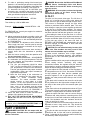
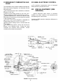
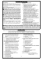
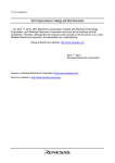
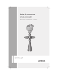
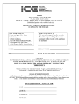
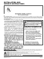
INSTALLATION AND
SERVICE INSTRUCTIONS
ECONOMITE MODEL F400B-33
Gas Conversion Burner
The ECONOMITE F400B-33 conversion burner with intermittent spark ignited pilot is adaptable to most gas utilization equipment,
including gravity and forced circulation furnaces and boilers. It is particularly recommended for firing horizontal or downdraft equipment
since it needs no draft to maintain a pilot. Power burner design makes it perfectly suited for oil burner replacement, including rooftop
and industrial applications.
In the United States, installation must conform with local codes
or, in the absence of local codes, with Installation of Domestic
Gas Conversion Burners, ANSI Z21.8b-1993, and National
WARNING: If the information in these
Fuel Gas Code, ANSI Z223.1-1992, or latest edition(s) available
instructions
is not followed exactly, a fire
from American National Standard Institute. Further reference
should be made to the recommendation of your fuel supplier.
or explosion may result causing property
NOTE: Any additions, changes, or conversions required in order
damage, personal injury or death.
for the appliance to satisfactorily meet the application needs
must be made by a MIDCO distributor (or other qualified agency)
Do not store or use gasoline or other
using factory specified approved parts.
In Canada, installation must conform with local codes or, in the flammable vapors and liquids in the vicinity
absence of local codes, with Installation Codes for Gas
Burning Appliances and Equipment, CGA Standard of this or any other appliance.
CAN/CGA1-B149.1 or 2. When the conversion burner is used
on a Forced air Central Furnace, the two yellow and black
WHAT TO DO IF YOU SMELL GAS
warning labels in the literature envelope shall be attached in
•
Do
not try to light any appliance.
accordance with Installation Code, CGa Standard CAN/CGA
• Do not touch any electrical switch;
1-B149, Clause 5.4.4.4. Further reference should be made to
the recommendation of your fuel supplier.
do not use any phone in your building.
INSTALLER: Inform and demonstrate to the user
the correct operation and maintenance of this
appliance. Inform the user of the hazards of
storing flammable liquids and vapors in the
vicinity of this appliance and remove such
hazards. Affix this manual adjacent to the
conversion burner.
CODE COMPLIANCE IS THE SOLE
RESPONSIBILITY OF THE INSTALLER.
USER: Retain this manual for future reference. If
other than routine service or maintenance as
described in this manual is required, contact
a
qualified service agency.
DO NOT
ATTEMPT REPAIRS. An inadvertent service
error could result in a dangerous condition.
• Immediately phone your gas supplier
from another building. Follow the gas
supplier's instructions.
• If you cannot reach your gas supplier,
call the fire department.
Installation and service must be
performed by a qualified installer,
service agency or the gas supplier.
SAFETY INFORMATION TERMS: The following terms are used to identify hazards, safety precautions or special notations and
have standard meanings throughout this manual. When you see the safety alert symbol and one of the safety information terms, as
shown below, be aware of the hazard potential.
DANGER: Identifies the most serious hazards which will result in severe personal injury or death.
WARNING: Signifies hazards that could result in personal injury or death.
CAUTION: Identifies unsafe practices which would result in minor personal injury or product and property damage.
MIDCO International Inc.
4140 WEST VICTORIA STREET, CHICAGO, ILLINOIS 60646 / (773) 604-8700 FAX: (773) 604-4070
PRINTED IN U.S.A.
1296
8470-73
SPECIFICATIONS
Standard burners are shipped as NATURAL gas models.
A kit is available for field conversion to PROPANE gas.
AIR DELIVERY (Approximate Air Delivery
at Zero Draft Maximum Firing)………………...146 SCFM1
MAXIMUM FIRING RATE2……………………………700 MBH3
MINIMUM FIRING RATE2…………………………….300 MBH3
GAS PRESSURE REQUIRED
NATURAL…………………………………5.0" to 14.0" W.C.
PROPANE……………………………….11.0" to 14.0" W.C.
TUBE DIAMETER……………………………………………….4"
TUBE LENGTH………………………………………………….8"
RECOMMENDED COMBUSTION CHAMBER SIZE
700 MBH………………………………15" W x 25" L
ELECTRICAL SUPPLY……120/1/60…10 Amp dedicated
service
FLAME SAFETY………Intermittent proven pilot ignition,
Electronic Safety
1. SCFM=Standard Cubic Feet/Minute.
2. Ratings based on 1000 BTU/Cu. Ft. Natural, 2500
BTU/Cu. Ft. PROPANE at Sea Level. Derate burner
for altitudes over 2,000 feet by 4% for each 1,000
feet above sea level.
3. 1 MBH=1,000 BTU/Hr.
One Gallon of Fuel Oil=140 MBH.
PART 1 INSTALLATION
CAUTION: The ECONOMITE F400B-33 is not
intended for outdoor installation and must be
protected from excessive moisture. Provide
adequate clearance for service and proper operation.
I
VENTILATION
If the former automatic oil burner gave trouble-free
operation, it is probable that the gas utilization equipment
area has sufficient infiltration of air for combustion and
dilution of flue gases. Nevertheless, the area must be
checked:
■ Open basement or utility areas of normal construction,
without storm windows or tight doors, will generally allow
sufficient air infiltration. However, if the gas utilization
FIGURE 1 Dry Base Boiler with Combustion Chamber
-2Liner (Warm Air Furnace Construction is Similar)
equipment is located in a tight or separate room,
ventilation to an open area as described above will be
required. Install two permanently open grilles, each sized
on the basis of one square inch free area per 1,000 BTU
of the total input rating of all gas utilization equipment in
the combined space. One grille should be located within
12 inches of the ceiling, the other within 12 inches of the
floor.
■ If the gas utilization equipment is located in an area of
unusually tight construction, or if an exhaust fan, kitchen
ventilation system, clothes dryer and/or fireplace is
installed in the building, provisions must be made for an
outside air supply near the heating appliance area. Install
permanently open grilles sized at not less than one
square inch free area per 4,000 BTU of burner input.
When ventilating through horizontal ducts, grilles should
be sized at not less than one square inch free area per
2,000 BTU of burner input. In any case, the minimum
dimension of rectangular air ducts shall not be less than
3 inches.
■ In Canada, for detailed ventilation requirements, refer
to standard CAN/CGA 1-B149.1 or .2 and/or local codes.
II PREPARATION OF THE GAS
UTILIZATION EQUIPMENT
■ Clean the gas utilization equipment, combustion
chamber, heat exchanger interior and flue connections.
Remove all adhering tars, scale, dirt and soot. Inspect for
actual or potential leaks.
■ Cement all joints, including those in the gas utilization
equipment base and around the door frames, to prevent
leakage into, or out of the combustion chamber.
■ The access or firing door should open easily to relieve
pressure. If positive latches exist, they should be
modified to permit easy opening; a spring loaded door
holder is recommended.
■ On all boilers, make certain the pressure relief safety
valve is in good operating condition.
FIGURE 2 Wet Base Boiler with Unlined
Combustion Chamber
III COMBUSTION CHAMBER
A combustion chamber liner is normally required to
protect non-heat transfer surfaces and to provide a
radiant bed for rapid heat transfer to the primary surfaces
of the heat exchanger. In most cases the existing
combustion chamber liner formerly used for oil burner
can be used, if in good condition.
■ In the case of wet base boilers, where the entire firing
chamber is comprised of heat exchange surfaces and no
chamber liner was provided for oil firing, a liner is usually
not required for the ECONOMITE. However, a liner or
target wall may be necessary if the firing chamber is
unusually short, in order to avoid flame contact on the
heat exchanger walls or flueways.
■ If a built up chamber liner is required, use 2,300°F
minimum insulating material.
■ The burner tube must be sealed air tight into the
combustion chamber opening with refractory material as
shown by Figures 1 and 2.
NOTE: In no case should the burner tube be allowed to
extend into the chamber proper; it must be set flush to 1"
short of the inside surface because high combustion
chamber temperatures will cause premature pilot,
electrode, burner tube and sleeve deterioration.
■ Special heat resistant alloy extension tubes and
instructions are available for those applications where
the burner tube is too short to reach the combustion
chamber (such as old-fashioned gravity warm air furnace
installations.)
WARNING: BURNER CABINET MUST BE
MOUNTED IN ORIENTATION SHOWN IN FIGURES 1
AND 2. ANY OTHER MOUNTINGS MAY CAUSE A
DANGEROUS CONDITION, AND WILL VOID BURNER
WARRANTY AND AGENCY APPROVALS. NONSTANDARD ARRANGEMENTS MAY BE AVAILABLE
FOR SOME MODELS-CONSULT FACTORY FOR
DETAILS REQUIRED.
■ Before permanently setting the burner in place, check
that the burner ports and pilot are free of foreign
materials, and also that the electrodes have not been
damaged or displaced. See Figure 7.
■ The Vent Connector shall be as short as possible.
The entire length shall be readily accessible for
inspection, cleaning and replacement.
■ The length of horizontal uninsulated Vent Connector
between chimney and a single gas utilization equipment
shall not exceed 75% of the height of the chimney above
the connector, or 100% if the Vent Connector is
insulated.
■ The Vent Connector shall be installed so as to avoid
turns or other construction features which create
excessive resistance to flow of vent gas. It shall be
installed without any dips or sags and shall slope upward
at least 1/4" per foot.
■ A manually operated damper shall not be placed in the
Vent Connector or chimney of any gas utilization
equipment.
■ The Vent Connector shall be firmly attached to draft
hood outlets and flue collars. Joints between sections of
connector piping shall be fastened by sheet-metal
screws or other approved means. The Vent Connector
shall be supported for the design and weight of the
material employed to maintain clearance and prevent
physical damage and separation of joints.
■ A draft hood or a barometric draft regulator shall be
installed in the same room or enclosure as the
equipment in such a manner as to prevent any difference
in the pressure between the hood or regulator and the
combustion air supply (see Figures 3 and 4). In no case
shall the relief opening of the draft hood or barometric
draft regulator be located at a point lower than the top of
the highest flue passage in the equipment.
■ Gas utilization equipment requiring controlled draft
may be equipped with a listed double acting barometric
draft regulator, if a approved by local codes.
■ A device which will automatically shut off gas to the
burner in the event of sustained backdraft is required. It
must be of the listed manual reset type and installed and
adjusted by a qualified service technician in accordance
with the manufacturer's instructions.
■ Refer to the gas utilization equipment manufacturer for
recommended vent connection requirements.
IV CHIMNEY, VENT CONNECTOR,
AND DRAFT CONTROL
WARNING: The chimney shall be inspected for
unsafe conditions such as deteriorated masonry and
excessive soot or other blockage or potential
blockage. Installation must conform with local codes
or in the absence of local codes with ANSI Z21.8b1993 and NFPA, ANSI Z223.1-1992.
WARNING: THE VENT CONNECTOR SHALL NOT
BE CONNECTED TO A CHIMNEY ALREADY
VENTING SOLID FUEL BURNING EQUIPMENT, AN
INCINERATOR OR AN OPEN FIREPLACE.
■ The Vent Connector shall be made of noncombustible, corrosion resistant material capable of withstanding the vent gas temperature produced by the gas
utilization equipment and of sufficient thickness to withstand physical damage.
-3-
FIGURE 3 Recommended Locations for Draft Hoods
FIGURE 4 Location for Barometric Draft Regulators
Figure 3 and 4: Copyright by the
American Gas Association.
Used by permission of the copyright holder.
V ELECTRICAL
Installation wiring and grounding to the burner must
conform to local codes, or, in their absence in the United
States to National Electric Code, ANSI/NFPA No. 701990, or latest edition; in Canada, to Canadian
Electrical Code Part 1, CSA Standard C22.1.
■ Use copper wire not less than 14 gage for line voltage
wiring. Hook up to a dedicated line with an on-off
disconnect switch and a minimum 10 Amp breaker.
■ The frame of the burner should be well grounded.
Normally the piping and/or electric conduit will provide
sufficient grounding. However, a ground lug is located in
control box used for positive grounding where insulated
pipe couplings are used or where any doubt exists
regarding grounding sufficiency.
■ Confirm that the polarity is correct—hot wire to strip
terminal L1, neutral L2—and that the neutral line is not
subject to induced low voltage (check L2 to earth
ground) from other equipment, as that can cause the
electronic control to malfunction.
■ Each installation must include suitable limit control(s).
Existing oil burner combination operating and limit
controls are normally NOT SUITABLE for gas burner
use.
CAUTION: Label all wires prior to disconnection
when servicing controls. Wiring errors can cause
improper and dangerous operation. Verify proper
operation after servicing.
VI PIPING
CAUTION: The available gas pressure should be
within the limits shown in SPECIFICATIONS section.
Excessive pressure will damage Combination Valve,
Regulator and manual valves. If the supply pressure
exceeds the 14.0" W.C. maximum, a suitable
intermediate main regulator must be installed ahead
of the Main Manual Shut-Off Valve shown in Figure 5.
■ The burner gas supply piping should branch off from
the main line as close to the gas meter as possible. Do
not connect to the bottom of a horizontal section. Use
new black pipe and malleable fittings free of cutting and
threading burrs or defects.
■ Provide a sediment trap, union and 1/8" pressure tap
in piping close to burner as shown in Figure 5.
■ Use pipe joint compound approved for use with Liquid
Petroleum Gases.
■ Piping must comply with local codes.
■ To obtain the maximum firing rate of 700 MBH, the
NATURAL gas supply piping must be sized to provide a
minimum of 5.0" W.C. pressure (11.0" W.C. PROPANE)
to the inlet of the combination valve when the burner and
all other gas utilization equipment are on.
CAUTION: Because it is difficult to accurately
control pressure during supply pipe leak testing, it is
recommended that all low pressure (14.0" W.C. max.)
components, both main and pilot, be disconnected
during testing. Exposing low pressure regulators
and valves, including manual valves, to pressures
over 1/2 PSIG (14" W.C.) will cause damage and void
all warranties.
DANGER: Explosion hazard.
Do not use oxygen for pressure testing.
An explosion could occur during initial start-up.
■ If the burner piping must be rearranged because of
space limitation, be sure to carry out the general
arrangement shown in Figure 5. Install the combination
valve in any position except up-side down.
■ When the burner is installed in jacketed equipment, if
is recommended that the Combination Valve be left
adjacent to the burner within the vestibule and the Main
Manual Shut-Off Valve be installed outside.
NOTE: If there is more than 1.0" W.C. differential in the
inlet pressure to the burner compared to when all other
gas utilization equipment are off, refer to Section IX.
PIPE SIZE TYPE OF GAS
1
1-1/4
NATURAL
PROPANE
NATURAL
PROPANE
1-1/2
NATURAL
PROPANE
2
NATURAL
CAPACITY-MBH
LENGTH OF PIPE
60
10
20
40
500 350
700 550 350 300
700 500 400
700 600
700 600
100
300
450
450
700
700
Source: Gas Engineers Handbook-1974
Industrial Press Inc. NY, NY
TABLE 1: Supply Pipe Capacities in MBH
VII MAIN GAS SPUD SELECTION
Burners are approved for use with NATURAL or
PROPANE gas and should be used only with the gas
specified on the rating plate.
■ The gas input should be set at the heating rate
determined by the building heat loss and/or heating plant
survey, but not exceeding the rated maximum input of
the heating appliance or burner.
■ F400B burners are shipped equipped for natural gas,
with the spud removed. Compare the gas input required
-4- with the spud capacities shown in the spud table and, if
necessary, install the spare spud (see Figure 7).
NATURAL GAS
PROPANE GAS
SPUD BURNER MANIFOLD
DRILL INPUT PRESSURE
SIZE
MBH1
W.C.2
SPUD
DRILL
SIZE
BURNER MANIFOLD
INPUT PRESSURE
MBH1
W.C.2
25/64
(.390)
300
400
2.0"
3.5"
#9 (.196)
#3 (.213)
300
350
7/163
(.437)
400
540
2.0"
4.0"
#1 (.228)
17/64 (.265)
400
540
SPUD
REMOVED
540
625
700
1.85"
2.5"
3.2"
9/32
(.281)
19/64 (.296)
3.
10.0"
4.
625
700
DATA IS APPROXIMATE AND BASED ON "0"
OVERFIRE PRESSURE AT SEA LEVEL OVERFIRE
TABLE 2: Spud Capacity and Preliminary Gas Settings
5.
1.
6.
2.
3.
Input range of spud. Adjust the main regulator to vary the
manifold gas pressure and burner input within the range
shown for a specific spud drill size. With PROPANE, do not
exceed 11.0" W.C. under any circumstances.
Approximate gas pressure at manifold gas pressure tap.
Drill out 25/64 spare spud to 7/16.
VIII INITIAL START-UP/ADJUSTMENT
WARNING: Ignition is automatic. Make spark
observations into combustion chamber only with
Main and Pilot Manual Shut-Off Valves closed.
Confirm that gas utilization equipment does not
contain any accumulated gases. Purge as described
in step 3 below.
1. Check the burner piping and valves for gas leaks by
applying a weak liquid soap solution to unions and
joints with the gas supply on. Leakage will be
indicated by the appearance of soap bubbles. Locate
and correct all gas leaks before proceeding.
WARNING: DO NOT USE OPEN FLAME.
2. Purging the air from the gas supply line at this step
will expedite first light-off.
7.
IMPORTANT: Purge outside the building.
Do not purge into the gas utilization equipment.
To purge the gas utilization equipment and chimney
of any accumulated gases, turn Manual Gas Cock
Knob on Combination Valve to OFF, close Pilot
Manual Shut-Off Valve, turn burner power on, and
set operating control to ON or thermostat to call for
heat. Let the blower run long enough to accomplish
four air changes, but not less than five minutes.
IMPORTANT:Make sure that the capacity range of
the installed spud and the preliminary combustion
air shutter setting are suitable for capacity rating of
the gas utilization equipment. Refer to Section VII
and Table 2.
RESET the Electronic Control by setting the
operating control to OFF or the thermostat below
room temperature for at least 30 seconds. See
Section XII.
Confirm that Main and Pilot Manual Shut-Off Valves
are open. Turn Manual Gas Cock Knob on
Combination Valve to ON.
Turn operating control to ON or set thermostat above
room temperature. After a 30 second pre-purge, the
pilot should ignite. Whenever the burner pilot fails to
light during the 15-second ignition trial, or if the
flame is lost during the burner run and is not
re-established within 15 seconds after the pre-purge,
the Electronic Control will shut off the Combination
Valve and LOCK OUT. To RESET the Electronic
Control for restart, de-energize the Electronic Control
by setting the operating control to OFF or thermostat
below room temperature for at least 30 seconds. If
burner still fails to light, turn it off and repeat from
step 5 above. Then if necessary, refer to the
TROUBLE CHART to isolate the problem.
WARNING: Repeated unsuccessful attempts
to light will result in accumulated gases in gas
utilization equipment and chimney. To prevent
these gases from reaching an explosive level,
periodically purge the gas utilization equipment
and chimney as described in step 3 above.
CONSTRUCTION MAY VARY BY BURNER APPLICATION REQUIREMENTS
FIGURE 5 Piping Connections
-5-
8. To make a preliminary setting of the burner input,
determine the manifold gas pressure required from
Table 2 and adjust the Combination Valve Main Gas
Pressure Regulator accordingly. See Section XI.
9. To determine the firing rate for NATURAL gas,
accurately time test dial for the number of seconds
for one revolution and use the following formula. All
other gas utilization equipment must be off.
3600 x test dial size x BTU value = BTU/Hr.
No. of seconds for one rev. test dial
Then divide by 1,000 for MBH value.
Example: 3600 x 1 x 1000 =180,000 BTU/Hr. =180
20
For PROPANE gas, consult your supplier for method of
determining firing rate.
10. Adjust combustion air shutter to provide a quiet, soft
blue flame with well defined orange and yellow tips
for NATURAL gas or with well defined yellow tips
for PROPANE gas.
11. The combustion air adjustment which affects the
flame length has been set wide open for average
conditions. Decrease the combustion air if a longer,
softer flame is desired.
12. Check the operation of the burner; start and stop it
several times with the thermostat or operating
control.
13. With the burner running, check the operation of all
limit and associated controls.
14. PERFORM THE FOLLOWING FINAL ADJUSTMENTS
for combustion and flue gas temperature. Take the
flue gas samples and temperature immediately
ahead of the draft control.
A. The flue gas temperature should be above
325°F but not exceeding 550°F. Excessive flue
gas temperatures will result in low efficiencies.
Low flue gas temperature may cause excessive
condensation. Reset gas input if necessary to
adjust stack temperature.
B. Make the final setting of the combustion air
shutter by checking the flue gases with an
ORSAT
or
similar
combustion testing
instrument. The carbon monoxide content
should conform to local codes, or in their
absence, to the level specified in the United
States or Canadian Standard referenced on the
front cover of this manual; and the carbon
dioxide content should be approximately 9.5%
for NATURAL and 12.1% for PROPANE, or
within the limits prescribed by local codes.
15. Check the draft control to make sure there is no
spillage of flue products into the room.
16. FILL OUT THE INSTALLATION ADJUSTMENT
DATA TAG and affix to the burner or gas utilization
equipment.
NOTE: For subsequent normal starting and shut off
procedure, refer to CONSUMER INSTRUCTIONS or to
the instruction plate mounted on the burner.
PART 2 SERVICE
CONSUMER CAUTION: Do not tamper with the
unit or controls. If trouble occurs, contact a qualified
Service Technician.
DANGER: Be sure that the Main and Pilot Manual
Shut-Off Valves, Combination Valve and Burner
Power Switch are turned OFF before removing any
parts for service.
WARNING: All cover plates, enclosed and guards
must be in place at all times except during
maintenance and servicing.
IX PILOT
The pilot is of the premix, blast type. The full force of
blower air is brought into the mixing tube where the
proper amount of gas is added through the pilot orifice.
This mixture is discharged through the pilot which
contains a perforated flame retention plate. The outer
holes diverge to spray the mixture against the side wall
of the pilot tip to provide flame retention. The mixture
through the center port provides the flame that contacts
the flame detection rod and also ignites the main gas.
■ Surrounding the base of the pilot flame is a conical
shroud which protects the flame against extraneous air
currents and inhibits "blow-off" from an overly rich flame.
■ The pilot gas orifice is the same size both for
NATURAL and PROPANE gas, consequently the gas
pressure required for PROPANE is lower than that
required for NATURAL gas.
CAUTION: Do not indiscriminately increase pilot
orifice size. Pilot troubles are rarely cured in this
manner and new troubles may be created.
■ Under normal conditions, with a slight negative
pressure in the combustion chamber, pilot operating
pressures are 3.5" W.C. NATURAL gas and 2.25" W.C.
PROPANE.
■ Some conditions which may require a change from the
normal setting include: extremely long tubing
connections between the regulator and pilot solenoid,
high negative or positive combustion chamber pressure,
actual air shutter setting and altitude extremes.
■ Do not subject the Pilot Solenoid or Pilot Regulator to
an inlet pressure over 14.0" W.C. See section VI PIPING
for high pressure gas. Note that the standard pilot
pressure regulator is not a tight shut-off and, during
standby, the outlet pressure will build up to the full inlet
pressure.
■ The spark rod is located on the center line of the pilot
and is positioned so the high tension voltage will arc to
the inside of the center port of the retention plate (see
Figure 7).
■ The flame rod must be positioned as shown in Figure
7 so that the electronic control will detect a proper flame.
Note that it is slightly above the centerline of the pilot.
■ Both the spark and flame rods are current carrying
conductors and, along with their connecting wires, must
be kept free of contact with conductive metal parts of the
burner. Rod insulators and wire insulators should be
clean, dry and free of cracks.
■ Rods are made from heat resistant alloys and can be
expected to have a long service life. They should be
routinely inspected, however, for corrosion or loss of
metal.
■ The pilot air tube must be kept free of kinks or inside
obstructions and its inlet end must be positioned per
-6- Figure 7, otherwise air flow could be reduced sufficiently
and adversely affect the pilot flame.
NOMINAL BTU/Cu. Ft.
NATURAL-1000
PROPANE-2500
PILOT GAS
PRESSURE
2.5"-4.0" W.C.
2.25"-3.5" W.C.
ORIFICE
DIAMETER
#55 WIRE DRILL
.052 DIA.
APPROX.
CAPACITY
7000
TABLE 3: Pilot Specifications
X MOTOR, BLOWER INTERLOCK &
CENTRIFUGAL ACTUATOR
NOTE: BEFORE SERVICING, mark with a scribe line or
measure opening of primary air controlling shutter, so
that it can be reset to its original position following
servicing.
■ Cleaning of the blower wheel is usually the only
service required. Need for cleaning is indicated if the
character of the flame indicates a deficiency of air. Motor
cooling air vents if present should also be cleaned at this
time.
■ The blower side plate, motor and wheel are removed
as an assembly. Disconnect the motor wires from the
motor terminal strip. Disconnect the motor conduit from
the motor and remove the side plate screws.
■ The blower wheel is equipped with a spring loaded
centrifugal actuator to operate an electrical interlock
switch so as to prevent the burner from firing if the blower
wheel is not running at its operating speed. When the
motor is off, the actuator spring forces the disk against
the switch plunger to push it past its operating point.
When running, the actuator pulls the disk clear of the
plunger.
■ To make a specific test of the interlock circuit:
1. Turn burner power OFF.
2. Turn Manual Gas Cock Knob on Combination
Valve to OFF.
3. Disconnect the motor wire from the motor relay
to keep the motor off.
4. Turn burner power ON and set the operating
control to ON or thermostat to call for heat.
Check for 24V between the Electronic Control
25V and 25V GND terminals.
A. No voltage: Interlock circuit OK.
B. Voltage present: check that switch bracket is
screwed down tight (see Figure 6). If so,
without disconnecting switch wires, remove
switch bracket and manually depress switch
plunger. If voltage is still present, or if the
plunger has to be depressed to where
dimension"A" of Figure 6 is less than 9/32"
when switch clicks over, replace the switch.
5. If the switch tests OK, check dimension "A" of
Figure 6 as follows:
Switch plunger free………………9/32 to 11/32"
Disk free…………………………...7/32 to 1/4"
Disk held all the way in………….15/32" min.
6. If plunger dimension is wrong, replace switch. If
disc dimension is wrong, check that the actuator
operates freely with a minimum movement of
1/4" from the free position. If movement is OK,
reposition blower wheel on motor shaft. If not,
replace wheel.
FIGURE 6 Motor, Blower and Interlock Assembly
-7-
XI REDUNDANT COMBINATION GAS
VALVE
XII S8680J ELECTRONIC CONTROL
■ For operation characteristics refer to Honeywell
Control literature provided with burner.
The Combination Valve contains a Manual Gas Shut-Off,
Main Gas Pressure Regulator, and Automatic Electric
Main Gas Valve.
■ The Combination Gas Valve is suitable for a maximum
pressure of 14.0" W.C.
■ When the gas supply pressure is over 14.0" W.C.,
special regulators are required. See Section VI Piping.
■ Should replacement or service be required, valve
manufacturer's instructions must be followed as outlined
in their information sheet.
■ The Main Gas Pressure Regulator is adjustable for
outlet pressure range of 2.0" W.C. to 5.0" W.C.
■ Outlet pressure settings must be checked while the
gas is flowing.
■ To adjust outlet pressure, remove the seal cap for
access to the adjusting screw. Turning the screw
clockwise will increase outlet pressure, counter
clockwise will decrease outlet pressure.
XIII
SPECIAL EQUIPMENT (OEM
VERSIONS)
Special equipment, either factory or contractor
installed, may cause variation in the procedures and
descriptions given in this manual.
Consult the OEM's manual to identify the differences in
the information.
FIGURE 7 General Assembly
-8-
CONSUMER INSTRUCTIONS
MAINTENANCE
LIGHTING INSTRUCTIONS
■ Keep the area around the burner clear and free of
combustible material, gasoline or other flammable liquids or
vapors. Do not obstruct burner air openings or ventilation grilles
for combustion air.
■ The motor features permanently lubricated ball bearings and
requires no routing oiling maintenance.
CAUTION: Check the burner flame periodically. A
proper NATURAL gas flame will appear blue at the burner
face with orange and yellow tips. A proper PROPANE gas
flame will appear blue at the burner face with yellow tips.
An improper flame which is too lean will appear short and
all blue or purple. Burner cleaning and/or readjustment
may be indicated by flames that are too rich or too lean.
WARNING: If any flame is observed when the burner is
on standby, or if the ignition spark or valve operator is
heard to come on before the motor reaches operating
speed, immediately turn off the manual gas control and
burner power. A dangerous condition has developed and
must be corrected. CONTACT A QUALIFIED SERVICE
TECHNICIAN FOR CLEANING, READJUSTMENT OR
REPAIR.
■ Check that the pilot ignition spark does not come on before
the motor reaches operating speed. If it does, the motor
interlock switch is defective and must be replaced. (See
Section X, Motor, Blower Interlock and Centrifugal Actuator).
See Figure 7.
1. SET OPERATING CONTROL TO OFF OR
THERMOSTAT BELOW ROOM TEMPERATURE.
2. TURN MANUAL GAS COCK KNOB ON
COMBINATION VALVE TO ON.
3. TURN BURNER POWER ON.
4. SET OPERATING CONTROL TO ON OR
THERMOSTAT TO CALL FOR HEAT.
5. IF THE PILOT FLAME IS NOT PROVEN WITHIN 15
SECONDS THE ELECTRONIC CONTROL WILL
SHUT OFF COMBINATION VALVE AND LOCK OUT.
IF THE PROOF OF FLAME IS LOST DURING
BURNER RUN AND THE PILOT IS NOT
REESTABLISHED WITHIN15 SECONDS AFTER 30SECOND PRE-PURGE, THE ELECTRONIC
CONTROL WILL SHUT OFF COMBINATION VALVE
AND LOCKOUT. TO RESET FOR RESTART, DEENERGIZE THE CONTROL BY SETTING THE
OPERATING CONTROL TO OFF OR THERMOSTAT
BELOW ROOM TEMPERATURE FOR AT LEAST 60
SECONDS.
6. REPEAT STEP 4 FOR RESTART.
TO SHUT OFF
1. TURN MANUAL GAS COCK KNOB ON
COMBINATION VALVE TO OFF.
2. TURN BURNER POWER OFF.
SHOULD OVERHEATING OF THE APPLIANCE OCCUR
1. Shut off the manual gas control to the appliance.
2. Do not shut off the control switch to the pump or blower.
WARNING: IF PROPANE GAS IS USED AND THE BURNER IS LOCATED IN A BASEMENT, CRAWL SPACE OR
CONFINING SPACE, CONTACT YOUR GAS SUPPLIER ABOUT INSTALLING A "GAS LEAK" WARNING DEVICE. PROPANE
GAS IS HEAVIER THAN AIR AND CAN SETTLE IN LOW AREAS OR CONFINED SPACES. THIS WOULD CREATE A
DANGER OF EXPLOSION OR FIRE. IF YOU SUSPECT A GAS LEAK, FOLLOW INSTRUCTIONS ON FRONT COVER OF THIS
MANUAL.
TROUBLE CHART
Make sure the thermostat and operating controls are calling for heat. Defective wiring or loose connections can simulate the
component defects outlined below. Check associated wiring before replacing a component.
ELECTRICAL AND FLAME CHECKS MUST BE MADE IN THE ORDER LISTED BELOW.
I.
II.
MOTOR WILL NOT RUN
A. Confirm 120V between strip terminals L1 and
L2 and verify the circuit polarity and electrical
ground between strip terminal L1 and burner
Ground.
B. Check for 120V between strip terminals L1 and L2.
1. No voltage, open circuit in operating controls.
2. No voltage, motor relay is defective.
3. Voltage present, motor is defective.
MOTOR RUNS CONTINUOUSLY, BUT NO FLAME
A. Confirm that both Main Manual Shut-Off and
Combination Gas Shut-Off Valves are in the
ON position.
B. After 30 second pre-purge, if the pilot flame is
not proven within 15 seconds, or if the proof of
flame is lost during the burner run and the pilot
is not re-established within 15 seconds, the
Electronic Control will lock out. To reset the
control for restart, de-energize the Electronic
Control by setting the operating control to OFF
or thermostat below room temperature for at
least 60 seconds.
C. Clogged pilot orifice.
D. Pilot regulator misadjusted or defective.
E. Defective spark electrode or ignition control.
F. Defective high tension wire.
G. Wrong pilot orifice.
H. Defective pilot valve.
I. Pilot air tube clogged.
J. Incorrect spark gap.
K. Pilot regulator vent clogged.
III. MOTOR RUNS, PILOT WILL NOT LIGHT, FLAME
SAFEGUARD REMAINS "SET".
A. Defective centrifugal actuator.
B. Defective blower interlock switch.
C. Slow motor.
D. Defective ignition control.
IV. PILOT LIGHTS, NO MAIN FLAME, RELAY LOCKS
OUT
A. Poor pilot flame adjustment.
B. Clogged pilot air tube.
C. Defective flame rod or wire.
D. Flame rod mislocated.
E. Spark interference.
F. Pilot regulator vent clogged.
G. Defective ignition control.
V. PILOT LIGHTS, NO MAIN FLAME, RELAY REMAINS
"SET".
A. Defective main gas valve.
B. Closed leak test cock.
C. Low gas pressure.
D. Grossly misadjusted main gas and air.
E. Defective ignition control.
VI. SPASMODIC START
A. Loose wiring.
*Normal Low Voltage: Burner on standby-24V min.
Burner running (Main Gas Valve
energized)-21V min.
-9-