1
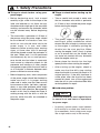
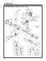
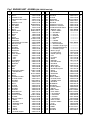
T4507-93110 (603) OWNER / OPERATOR MANUAL POWER AUGER AG4300 (NOTE: Drill is optional part.) WARNING The engine exhaust from this product contains chemicals known to the State of California to cause cancer, birth defects or other reproductive harm. Thank you for purchasing a RedMax product. Before using our power auger, please read this manual carefully to understand the proper use of your unit. APPLICABLE SERIAL NUMBERS : 100101 and up Read this manual carefully to understand all safety precautions, controls, proper operation and maintenance of your RedMax power auger. Failure to do so could result in serious injury. SAFETY FIRST Instructions contained in warnings within this manual marked with a symbol concern critical points which must be taken into consideration to prevent possible serious bodily injury, and for this reason you are requested to read all such instructions carefully and follow them without fail. Note that there may be times when warning seals peel off or become soiled and impossible to read. If this happens, you should contact the dealer from which you purchased the product to order new seals and affix the new seal(s) in the required location(s). ■ Notes on types of warnings WARNING IMPORTANT NOTE Instructions labeled as shown at left concern critical steps or procedures which must be followed in order to prevent accidents which could lead to serious bodily injury or death. This mark is used to indicate instructions which must be followed without exception. Instructions labeled as shown at left concern steps or procedures which, if not followed correctly, could lead to mechanical failure, breakdown, or damage. Used to label supplementary instructions designed to provide hints or directions useful in the use of the product. CONTENTS 1. SAFETY PRECAUTIONS .............................................................................. 4 IN ORDER TO ENSURE PROPER AND SAFE OPERATION OF YOUR POWER AUGER WORK GEAR AND CLOTHING WARNINGS CONSIDERING HANDLING OF FUEL THINGS TO CHECK BEFORE USING YOUR POWER AUGER THINGS TO CHECK BEFORE STARTING UP THE ENGINE AVOID NOISE PROBLEM THINGS TO BE CAREFUL ABOUT WHEN USING YOUR POWER AUGER NOTES ON CARE AND MAINTENANCE OF YOUR POWER AUGER 2. FUEL .............................................................................................................. 9 HOW TO MIX FUEL FUELING THE UNIT 3. OPERATION ................................................................................................. 11 INSTALLING LEFT GRIP INSTALLING DRILL THROTTLE CABLE PLAY STARTING ENGINE STOPPING ENGINE DRILLING ADJUSTING CARBURETOR 4. MAINTENANCE ........................................................................................... 14 DAILY INSPECTION PERIODICAL INSPECTION 5. STORAGE .................................................................................................... 16 BEFORE LONG-TERM STORAGE 6. SPECIFICATIONS ........................................................................................ 16 7. PARTS LIST ................................................................................................. 17 1. Safety Precautions ■ In order to ensure proper and safe operation of your power auger • Avoid running the engine indoors. The exhaust gases contain harmful carbon monoxide. • Read this Owner/Operator Manual carefully. Be sure you understand how to operate this unit properly before you use it. Failure to do so could result in serious injury. • Be sure to keep this manual handy so that you may refer to it later whenever any questions arise. Also note that you are requested to contact the dealer from whom you purchased the product for assistance in the event that you have any questions which cannot be answered herein. • Always be sure to include this manual when selling, lending, or otherwise transferring the ownership of this product. • This product has been designed for use in earth drilling, and it should never be used for any other purpose since doing so could result in unforeseen accidents and injuries occurring. • You should never use this power auger when under the influence of alcohol, when suffering from exhaustion or lack of sleep, when suffering from drowsiness as a result of having taken cold medicine, or at any other time when a possibility exists that your judgment might be impaired or that you might not be able to operate the power auger properly and in a safe manner. Also be sure never to allow children or anyone unable to fully understand the directions given in this manual to use this power auger. 4 • Never use your power auger under circumstances like those described below: 1. When the ground is slippery or when other conditions exist which might make it not possible to maintain a steady posture while using the power auger. 2. At night, at times of heavy fog, or at any other times when your field of vision might be limited and it would be difficult to gain a clear view of the area where the power auger is to be used to ensure safety. 3. During rain storms, during lightning storms, at times of strong or gale-force winds, or at any other times when weather conditions might make it unsafe to use this product. • When using this product for the first time, before beginning actual work, take the power auger to a wide, clear, open space, turn on the power, and practice handling the power auger until you are sure that you will be able to handle in it properly in actual operation. • Lack of sleep, tiredness, or physical exhaustion results in lower attention spans, and this in turn leads to accidents and injury. When planning your work schedule, allow plenty of time to perform the work of cutting and allow plenty of time for rest. Limit the amount of time over which the power auger is to be used continuously to somewhere around 30~40 minutes per session, and take 10~20 minutes of rest between work sessions. Also try to keep the total amount of work performed in a single day under 2 hours or less. 1. Safety Precautions ■ Work gear and clothing ■ Warnings considering handling of fuel • When using your power auger, always be sure to wear strong, durable, work clothing; shirts should be long-sleeved shirts and pants should be full-length pants reaching down to the ankles. • The engine of the power auger is designed to run on a mixed fuel which contains highly flammable gasoline. This fuel is highly flammable and you should never store cans of fuel or refill the tank of the power auger in any place where there is a boiler, stove, wood fire, electrical sparks, welding sparks, or any other source of heat or fire which might ignite the fuel. • Always be sure to wear and helmet and face protector when using your power auger. • When using your power auger, always be sure to wear thick work gloves to protect your hands and non-slip-sole work boots to prevent you from slipping. Never use your power auger when wearing pants with loose cuffs, when wearing sandals, or when barefoot. • When using your power auger for an extended period of time, you should wear ear protectors to protect yourself from loss of hearing from overexposure to high levels of sound. • Smoking while operating the power auger or refilling its fuel tank is extremely dangerous. Always be sure to keep lit cigarettes away from the power auger at all times. • When refilling the tank always turn off the engine first and take a careful look around to make sure that there are no sparks or open flames anywhere nearby before refueling. • If any fuel spillage occurs during refueling, always be sure to use a dry rag to wipe any fuel which has been spilled onto the power auger before turning the engine back on again. • After refueling, screw the fuel cap back tightly onto the fuel tank and then carry the power auger to a spot 10 feet or more away from where it was refueled before turning on the engine. 5 1. Safety Precautions ■ Things to check before using your power auger ■ Things to check before starting up the engine • Before beginning work, look around carefully to get a feel for the shape of the land, and whether or not there are any obstacles which might get in the way while working, and remove any obstacles which can be cleared away before beginning work. • Take a careful look around to make sure that no obstacles exist within a perimeter of 15 feet or less around the power auger before starting the engine. • The area within a perimeter of 45 feet of the person using the power auger should be considered a hazardous area into which no one should enter while the power auger is in use, and when necessary yellow warning rope, warning signs, or some other form of warnings should be placed around the perimeter of the area. When work is to be performed simultaneously by two or more persons, care should also be taken to constantly look around or otherwise check for the presence and locations of other people using power auger within the work area so as to maintain a distance between each person sufficient to ensure safety. • Before beginning work, each component of the power auger should be checked to make sure that it is in proper working order and to make sure that there are no loose screws or bolts, fuel leaks, ruptures, dents, or any other problems which might interfere with safe operation. Be especially careful at this time to check that there is nothing wrong with the drills or with the joints by which the drills are attached to the power auger. • The power auger is equipped with a centrifugal clutch mechanism which causes the drills to begin to rotate as soon as the engine is started by putting the throttle into the start position. When starting the engine, hold it firmly in place so as to ensure that nor the throttle may not come into contact with any obstacles when the engine starts up. • Never place the throttle into the high speed position when starting the engine. • After starting up the engine, check to make sure that the drills stop rotating when the throttle is moved fully back to its original position. If the drills continue to rotate even after the throttle has been moved fully back, turn off the engine and take the unit to your authorized Red Max servicing dealer for repair. ■ Avoid noise problem NOTE Check and follow the local regulations as to sound level and hours of operations for power auger. • In general, operate power auger between 8a.m.and 5p.m.on week days and 9a.m.to 5p.m.weekends. Avoid using power auger late at night and/or early in the morning. 6 1. Safety Precautions ■ Things to be careful about when using your power auger • When using your power auger, grip the handles of the power auger firmly with both hands, place your feet slightly apart (slightly further apart than the width of your shoulders) so that your weight is distributed evenly across both legs, and always be sure to maintain a steady, even posture while working. • Maintain the speed of the engine at the level required to perform drilling work, and never raise the speed of the engine above the level necessary. • Always be sure never to allow other persons to come within the work area while drilling. • Be especially careful not to slip if it is raining or if rain has just stopped, as the ground is likely to be slippery at such times. • If the grass or other object gets caught in the drill during operation, always be sure to turn off the engine before removing the object. • Guard against hazardous situations at all times. Warn adults to keep pets and children away from the area. Establish a safe method for gaining your attention during operation. Be careful if you are approached. • If someone calls out or otherwise interrupts you while working, always be sure to turn off the engine before turning around. • Keep operation area clear of all persons, particularly small children and pets. • Never touch the spark plug or plug cord while the engine is in operation. Doing so may result in being subjected to an electrical shock. • Never touch the muffler, spark plug, or other metallic parts of the engine while the engine is in operation or immediately after shutting down the engine. These metallic parts reach high temperatures during operation and doing so could result in serious burns. • When you finish drilling in one location and wish to continue work in another spot, turn off the engine before carrying it to the new location. • Never transport the power auger over rough roads over long distances without first removing all fuel from the fuel tank, as doing so might cause fuel to leak from the tank as a result of shocks absorbed during transport. 7 1. Safety Precautions ■ Notes on care and maintenance of your power auger • In order to maintain your power auger in proper working order, perform the maintenance and checking operations described in this manual at regular intervals. In the event that any parts must be replaced or any maintenance or repair work not described in this manual must be performed, please contact a representative from the store nearest RedMax authorized servicing dealer for assistance. • Under no circumstances should you ever take apart the power auger or alter it in any way. Doing so might result in the power auger becoming damaged during operation or the power auger becoming unable to operate properly. • Always be sure to turn off the engine before performing any maintenance or checking procedures. • When removing, or reattaching the drills, be sure to wear thick, sturdy gloves and use only proper tools and equipment to prevent injury. • When replacing drills or any other parts or when replacing the oil or any lubricants, always be sure to use only RedMax products or products which have been certified by RedMax for use with the power auger. • Do not use any accessory or attachment other than those bearing the RedMax mark and recommended for the unit. 8 2. Fuel WARNING • Gasoline is very flammable. Avoid smoking or bringing any flame or sparks near fuel. Make sure to stop the engine and allow it cool before refueling the unit. Select outdoor bare ground for fueling and move at least 3m (10ft) away from the fueling point before starting the engine. • The RedMax engines are lubricated by oil specially formulated for air-cooled 2-cycle gasoline engine use. If RedMax oil is not available, use an anti-oxidant added quality oil expressly labeled for air-cooled 2-cycle engine use. (JASO FC GRADE OIL or ISO EGC GRADE) • Do not use BIA or TCW (2-stroke watercooling type) mixed oil. ■ RECOMMENDED MIXING RATIO GASOLINE 50:OIL 1 (when using ZENOAH genuine oil) 50:1 MIXING CHART GASOLINE gal. 1 2 3 4 5 2-CYCLE OIL fl.oz 2.6 5.2 7.8 10.4 13 GASOLINE liter 2-CYCLE OIL ml 1 20 2 40 3 60 4 80 5 100 • Exhaust emission are controlled by the fundamental engine parameters and components(eq., carburation, ignition timing and port timing) without addition of any major hardware or the introduction of an inert material during combustion. • These engines are certified to operate on unleaded gasoline. • Make sure to use gasoline with a minimum octane number of 89 RON (USA/Canada: 87AL) • If you use a gasoline of a lower octane value than prescribed, there is a danger that the engine temperature may rise and an engine problem such as piston seizing may consequently occur. • Unleaded gasoline is recommended to reduce the contamination of the air for the sake of your health and the environment. • Poor quality gasolines or oils may damage sealing rings, fuel lines or fuel tank of the engine. ■ HOW TO MIX FUEL IMPORTANT Pay attention to agitation. 1. Measure out the quantities of gasoline and oil to be mixed. 2. Put some of the gasoline into a clean, approved fuel container. 3. Pour in all of the oil and agitate well. 4. Pour In the rest of gasoline and agitate 9 2. Fuel again for at least one minute. As some oils may be difficult to agitate depending on oil ingredients, sufficient agitation is necessary for the engine to last long. Be careful that, if the agitation is insufficient, there is an increased danger of early piston seizing due to abnormally lean mixture. 5. Put a clear indication on the outside of the container to avoid mixing up with gasoline or other containers. 6. Indicate the contents on outside of container for easy identification. ■ FUELING THE UNIT 1. Untwist and remove the fuel cap. Rest the cap on a dustless place. 2. Put fuel into the fuel tank to 80% of the full capacity. 3. Fasten the fuel cap securely and wipe up any fuel spillage around the unit. WARNING 1. Select bare ground for fueling. 2. Move at least 10feet (3meters) away from the fueling point before starting the engine. 3. Stop the engine before refueling the unit. At that time, be sure to sufficiently agitate the mixed gasoline in the container. FOR YOUR ENGINE LIFE, AVOID; 1. FUEL WITH NO OIL(RAW GASOLINE) – It will cause severe damage to the internal engine parts very quickly. 2. GASOHOL – It can cause deterioration of rubber and/or plastic parts and disruption of engine lubrication. 3. OIL FOR 4-CYCLE ENGINE USE – It can cause spark plug fouling, exhaust port blocking, or piston ring sticking. 4. Mixed fuels which have been left unused for a period of one month or more may clog the carburetor and result in the engine failing to operate properly. 10 5. In the case of storing the product for a long period of time, clean the fuel tank after rendering it empty. Next, activate the engine and empty the carburetor of the composite fuel. 6. In the case of scrapping the used mixed oil container, scrap it only at an authorized repository site. NOTE As lot details of quality assurance, read the description in the section Limited Warranty carefully. Moreover, normal wear and change in product with no functional influence are not covered by the warranty. Also, be careful that, if the usage in the instruction manual is not observed as to the mixed gasoline, etc. described therein, it may not be covered by the warranty. 3. Operation F1 ■ INSTALLING LEFT GRIP (F1) • Screw in the left grip to the bracket provided on the frame and tighten the lock nut securely. (1) Left grip (2) Bracket (3) Lock nut F2 ■ INSTALLING DRILL (F2) 1. Slide the ring clip and remove the lock pin from the drill. 2. Put the drill onto the auger output shaft and insert the lock pin. Cover it with the ring clip. (1) PTO shaft (2) Clip band (3) Drill (4) Pin F3 ■ THROTTLE CABLE PLAY (F3) • Check the throttle cable play and adjust to 1~2mm(.04~.08in.) as necessary. (1) Lock nut (2) Big (3) Small F4 ■ STARTING ENGINE 1. Fill fuel and tighten the cap securely. 2. Put the switch to “START” position. (F4) 3. Close the choke. (F5) NOTE When restarting immediately after stopping the engine, Ieave the choke open. (F5) F5 4. Push the primer pump until overflown fuel flows out in the clear tube. (F5) NOTE The pump operation is not necessary when restarting the engine immediately after stopping it. 5. Push the start set button of the handle left 11 3. Operation aspect while holding the throttle lever, and set the throttle lever in the start position. (F6) F6 (1) Engine switch (2) Start (3) Stop (4) Choke lever (5) Open (6) Close (7) Primer pump (8) Throttle lever (9) Lock button F7 6. While supporting the auger with your left waist and left hand as shown in the figure, pull the starter rope, first lightly and add force when compression is felt. (F7) WARNING Keep the drill clear of everything around it as it will start rotating upon starting of engine. 7. When the engine has started, gradually open the choke and release the throttle lever. 8. Alow the engine to warm up for a half minutes before starting operation. NOTE • When re-starting immediately after stopping the engine, keep the choke open. • If the engine won’t start after repeated attempts, it may be overfed with fuel. Remove and dry the spark plug, and try to start again with the choke open. F8 ■ STOPPING ENGINE 1. Release the throttle lever to allow the engine idling for a few minutes 2. Put the switch to the “STOP” position. (F8) (1) Engine switch ■ DRILLING (F9) • Keep a firm grip of the auger at all times on a wide stance and by holding the handle with both 12 3. Operation F9 F10 hands. • A reacting motion may occur on the auger when spinning drill has hit on stones or tree roots under the ground. Always hold the auger securely to control such motion. • Start drilling with half-throttle, and gradually increase the engine speed so that the drill may get into the ground smoothly. • When the drill has been caught in the ground and cannot be pulled out, stop the engine and rotate the auger counter-clockwise. ■ ADJUSTING CARBURETOR (F10,11,12) The carburetor on your unit has been factory adjusted, but may require fine tuning due to change in operating conditions. Before adjusting the carburetor, make sure that provided are clean air/fuel filters and fresh, properly mixed fuel. 1. Stop engine and screw in both H and L needles until they stop. Never force. Then set them back the initial number of turns as shown below. F11 F12 H needle: 13⁄8 ± 1⁄4 L needle: 11⁄4 ± 1⁄4 2. Start engine and allow it to warm up at halfthrottle. 3. Turn L needle slowly clockwise to find a position where idling speed is maximum, then set the needle back a quarter (1/4) turn counterclockwise. 4. Turn idle adjusting screw counterclockwise so that the drill does not turn. If idling speed is too slow, turn the screw clockwise. 5. Make a test run and adjust the H needle for best drilling power, not for maximum speed. (1) Idle adjusting screw (2) rpm up (3) rpmdown (4) H-needle (5) Fuel decrease (6) Fuel increase (7) L-needle (8) Fuel decrease (9) Fuel increase 13 4. Maintenance Maintenance, replacement, or repair of the emission control device and systems may be performed by any non-road engine repair establishment or individual. WARNING Before cleaning, inspecting or repairing the auger, make sure that the engine has stopped and cooled down. Disconnect the spark plug terminal to avoid accidental engine starts. ■ DAILY INSPECTION • Check all nuts and screws are securely tightened and no parts are missing. • Check for leakage of fuel. ■ PERIODICAL INSPECTION F13 AIR FILTER (F13) Check the air filter every 50 hours of use or more frequently if used under very dusty condition, and clean the element in warm soapy water as necessary. Dry completely before installing. (1) Cover (2) Element F14 .025 in 0.655mm F15 SPARK PLUG (F14) Check the spark plug every 50 hours of use and clean the gap with a wire brush. The gap should be set to .025 in. When replacing with a new plug, use a Champion RCJ-6Y or NGK BPMR7A. FUEL FILTER (F15) A clogged fuel filter can cause lack of power and poor pickup. Check the fuel filter every 25 use hours. 1. With a small wire hook, pull the fuel line and filter out of tank. 2. Disconnect the filter assembly. 3. If necessary, replace with new filter or clean by blowing air inside out after spraying a carburetor cleaning solvent. (1) Fuel filter 14 4. Maintenance F16 CYLINDER FINS (F16) Dust clogging between the cylinder fins will cause overheating of the engine. Periodically check and clean the cylinder fins. (1) Intake air cooling vent F17 SPARK ARRESTER (F17) This engine is equipped with a spark arresting screen at the exhaust port. Check periodically to see if it is good condition, especially when your machine is to be used on any forest covered, brush covered, or grass covered unimproved land. In the State of California the above is required by law (Section 4442 of the California Public Resources Code) 1. Remove the muffler guard and pry off the spark arrester from the exhaust port. 2. Clean the metal screen with a wire brush. If damaged, replace with new one. (1) Muffler guard (2) Spark arrester F18 GEAR BOX Check oil level of the gear box every 50 hours of use and change with new oil as necessary. (SAE #80 - 90) Recommended change interval 1st: After 50 hours of use 2nd and on: Every 100 hours of use (1) Oiling port (2) Oil drain port (3) Oil level CLUTCH Disconnect the engine from the gear box and check the clutch condition every 100 hours of use. Wipe off oil attached to the drum and shoes, and replace parts with a new one if found to be worn. 15 5. Storage ■ Before Long-term Storage • Drain fuel tank and run engine out until all fuel in the carburetor is used up. • Remove the spark plug and drop a spoonful 2 cycle oil into the cylinder. Crank the engine several times and replace the plug. Pull starter until compression is felt. • Brush off dirt from the drill surface and apply rust protective oil. • Store the machine in a dry, dust-free place. 6. Specifications Model Name ...................................................................................................................AG4300 Engine Displacement cu.in(cc) ........................................................................................2.53 (41.5) Maximum power kW(HP) ....................................................................1.5 (2.0) at 7000 rpm Carburetor ...........................................................................Diaphragm type (Walbro WYK) ignition system ...............................................................................................Electric (T.C.I) Spark plug .....................................................................................................NGK BPMR7A Starter .............................................................................................................Recoil starter Fuel .............................................................................2 cycle oil premixed gasoline (50:1 ) (when using ZENOAH genuine oil) Fuel tank capacity fl.oz(lit) .............................................................................................32 (0.94) Transmission .................................................................Centrifugal clutch, worm gear reduction Gear box lubricant .......................................................................................Gear oil SAE#80-90 Reduction ratio .....................................................................................................................45:1 Grip span in (mm) .......................................................................................................21.2 (540) Over all dimensions Length in (mm) .....................................................................................................24.8 (630) Width in (mm) .......................................................................................................14.4 (359) Height w/o drill in (mm) ........................................................................................11.7 (292) Dry weight w/o drill Ids (kg) ..........................................................................................19.3 (8.9) Adaptable drill size Diameter in (mm) ...................................................................................0.8 to 8 (20 to 200) Specifications are subject to change without notice. 16 7. Parts list POWER AUGER AG4300 NOTE : 1. Use KOMATSU ZENOAH genuine parts as specified in the parts list for repair and/or replacement. 2. KOMATSU ZENOAH does not warrant the machines, which have been damaged by the use of any parts other than those specified by the company. 3. When placing parts orders for repair and/or replacement, check if the model name and the serial number are applicable to those specified in the parts list, then use parts number described in the parts list. 4. The contents described in the parts list may change due to improvement. 5. The parts for the machine shall be supplied seven (7) years after the machine is discontinued. [It is possible that some specific parts may be subject to change of their delivery term and list price within the limit of ten (7) years after the machine is discontinued. It is also possible that some parts may be available even after the limit of seven (7) years.] APPLICABLE SERIAL NUMBERS : 100101 and up July. 2001 17 7. Parts list Fig.1 ENGINE UNIT AG4300 (S/N 100101 and up) 18 Fig.1 ENGINE UNIT AG4300 (S/N 100101 and up) Key# 1 2 3 4 5 6 7 8 9 10 11 12 13 14 15 16 17 18 19 20 21 22 23 24 25 26 27 28 29 30 31 32 33 34 35 36 37 38 39 40 41 42 43 44 45 46 47 48 49 50 51 52 53 54 55 56 57 58 59 60 Description Part Number CYLINDER 848-G6D-12A0 BOLT 1850-12130 GASKET,base 4500-13120 CRANKCASE COMP. 4500-21101 • PIN 2629-21130 GASKET,case 4500-21140 BEARING 06030-06201 OIL SEAL 4810-21210 OIL SEAL 1650-21220 BOLT 01252-30530 SNAP RING 04065-03212 PISTON 4500-41110 RING 1400-41220 PIN 2850-41310 RING 1300-41320 BEARING T2100-41410 WASHER 2850-41510 CRANKSHAFT COMP. 4500-42000 SHOE,clutch 4500-51111 SPRING 4500-51220 SCREW 1200-51211 WASHER 1200-51230 WASHER 1200-51241 ROTOR 4500-71110 COIL ASS'Y 4500-71200 • CORD 4500-71220 • CAP 2616-71320 • PIN 3356-21130 GROMMET 5500-72130 CAP,plug 5500-72110 SPRING 1900-72120 BOLT 4500-72150 NUT 1650-43230 KEY 1000-43240 MUFFLER ASS'Y T1007-15100 • ARRESTER 1601-15120 BOLT 01252-30565 BOLT 3310-31720 GASKET,muffler 4700-15211 PLATE,muffler 4500-15221 SCREW 0263-90514 COVER 4500-31110 BOLT 3310-12281 PLATE 4500-31210 COVER 4500-32110 SCREW 4500-32120 GUARD 4500-32210 SPARKPLUG 5602-73110 GROMMET 1852-72121 CORD COMP. T1007-73200 CLAMP 848-8K4-0010 RECOIL ASS'Y T1123-75100 • REEL 4500-75120 • SCREW 4500-75150 • SPRING,spiral 1850-75130 • COLLAR 4500-75180 • ARM 4500-75190 • ROPE 4500-75160 • KNOB 1140-75320 • PLATE,stopper 5500-75170 Q'ty Key# 1 4 1 1 3 1 2 1 1 4 1 1 2 1 2 1 2 1 2 1 2 2 2 1 1 1 1 2 1 1 1 2 1 1 1 1 2 1 1 1 1 1 4 1 1 4 1 1 1 1 1 1 1 1 1 1 1 1 1 1 61 62 63 64 65 66 67 68 69 70 71 72 73 74 75 76 77 78 79 80 81 82 83 84 85 86 87 88 89 90 91 92 93 94 95 96 97 98 99 100 101 102 103 104 105 106 107 108 109 110 111 112 113 114 115 116 117 118 119 Description PULLEY SCREW PLATE WASHER INSULATOR SCREW GASKET,insulator GASKET,carburetor CARBURETOR ASS'Y • REBUILT KIT • • BODY ASS'Y • • • SCREEN • • • VALVE • • • SPRING • • • SCREW • • • PIN • • • LEVER • • GASKET KIT • • • DIAPHRAGM • • • GASKET,diaphragm • • • DIAPHRAGM,pump • • • GASKET,pump • BODY,purge • COVER,pump • PUMP,priming • JET • O-RING • RING • SWIVEL • VALVE ASS'Y • SCREW • BRACKET • NUT,adjuster • SCREW,adjuster • RING • SCREW • WASHER SCREW BODY ASS'Y • PLATE,choke • LEVER,choke • SCREW ELEMENT SCREEN COVER ASS'Y • KNOB TANK ASS'Y • CAP ASS'Y • • HOLDER-A • • PACKING • • FILTER • • STOPPER • PIPE COMP. • FILTER ASS'Y • CLIP SCREW LABEL GUARD SCREW Part Number 4500-75210 4500-75511 4500-75310 01643-30823 4500-13161 4500-13181 4500-13150 4500-13130 T1007-81000 5602-06030 1850-81450 ––––––––– ––––––––– ––––––––– ––––––––– ––––––––– ––––––––– 5602-06020 ––––––––– ––––––––– ––––––––– ––––––––– 1850-81490 1850-81520 1751-81510 T1007-81250 1751-81240 1751-81130 1881-81140 ––––––––– 1752-81110 5500-81120 1751-81180 1918-81170 1881-81130 1850-81530 5500-81160 0263-90550 4500-82100 4500-82130 4500-82140 2630-33610 4500-82170 4500-82180 4500-82202 5500-82221 T1015-85004 T1015-85202 4500-85300 4500-85220 5601-85260 4820-85260 T1015-85300 3302-85400 1260-85460 1600-86120 T1133-75411 4500-22110 0263-90514 Q'ty 1 4 1 1 1 2 1 1 1 1 1 – – – – – – 1 – – – – 1 1 1 1 1 1 1 1 2 1 1 1 1 4 1 2 1 1 1 1 1 1 1 1 1 1 1 1 1 1 1 1 1 4 1 1 1 19 7. Parts list Fig.2 DRILL and ACCESSORY GROUP AG4300 (S/N 100101 and up) 20 Fig.2 DRILL and ACCESSORY GROUP AG4300 (S/N 100101 and up) Key# Part Number 1 2 3 4 5 6 7 8 9 10 11 12 13 14 15 16 17 18 19 20 21 22 23 24 3209-11103 3209-11203 1800-21281 3202-11260 0260-30620 06000-06304 3202-11311 3202-11320 3200-11330 07000-02012 04065-06220 3202-11361 2510-23230 0224-40610 3010-31380 3205-21110 3200-21121 3200-21130 3206-21210 3205-21220 3200-21230 3202-21240 3200-21250 6468-91150 Gear Case Comp Cover Comp Oil Seal Gasket Screw Bearing Retainer Oil Seal O-Ring O-Ring Snap Ring Plug O-Ring Bolt Gasket Worm Collar Drum Shaft Wheel Washer Washer Shim Bolt Description 26 27 28 29 30 31 32 33 34 35 36 37 38 39 40 41 42 43 44 45 46 47 48 49 50 51 52 53 54 55 56 57 58 59 60 01010-50620 01602-20619 01643-30623 3209-31123 3206-31130 0225-50630 3206-31202 3206-31212 3206-31220 1000-15150 0280-10605 0290-20615 3204-31300 3204-31310 4050-14220 0281-11411 T4507-12511 3206-91001 3541-91110 1030-91340 3239-91310 3540-91120 3540-93120 3202-51102 3202-51121 3200-51130 3200-51140 3206-52100 3202-52121 01225-40620 0280-10605 0290-20615 3206-52330 3200-51130 3200-51140 Bolt Washer Washer Holder Spacer Bolt Bracket Ass'y • Bracket • Mount • Nut • Nut • Washer Left Handle Comp • Handle-L • Grip • Nut Name Plate Tool set • Bag • Screwdriver • Socket • Spanner Band S40 Drill Ass'y (1.6in dia.) • Bit • Pin • Clip S60 Drill Ass'y (2.4in dia.) • Tip, S60 • Screw • Nut • Washer • Bit • Pin • Clip Q'ty Key# Part Number Description Q'ty 1 1 1 1 6 1 1 1 1 1 1 1 1 1 1 1 1 1 1 1 1 2 0~3 4 61 62 63 64 65 66 67 68 69 70 71 72 73 74 75 76 77 78 79 80 81 82 83 84 85 86 87 88 89 90 91 92 93 94 95 96 97 98 99 100 101 102 103 104 3206-52200 3206-52220 01225-40620 0280-10605 0290-20615 3206-52330 3200-51130 3200-51140 3206-52300 3206-52320 01225-40620 0280-10605 0290-20615 3206-52330 3200-51130 3200-51140 3206-52400 3202-52420 01225-40620 0280-10605 0290-20615 3206-52330 3200-51130 3200-51140 3206-61100 3206-61120 6468-91150 0280-10605 3200-51130 3200-51140 3204-53100 3200-51130 3200-51140 3204-53200 3200-51130 3200-51140 1075-96100 1400-96210 1400-96300 3206-91610 3206-91620 3206-53430 3206-53410 3206-53420 S90 Drill Ass'y (3.5in dia.) • Tip, S90 • Screw • Nut • Washer • Bit • Pin • Clip S150 Drill Ass'y (5.9in dia.) • Tip, S150 • Screw • Nut • Washer • Bit • Pin • Clip S200 Drill Ass'y (7.9in dia.) • Tip, S200 • Screw • Nut • Washer • Bit • Pin • Clip L150 Drill Ass'y (5.9in dia.) • Blade • Bolt • Nut • Pin • Clip L100 Joint Ass'y • Pin • Clip L300 Joint Ass'y (11.8in.) • Pin • Clip Puller Ass'y Set Block Rod Ass'y Spanner Rod Tip, S300 Tip, S200 Tip, S250 1 1 2 2 2 1 1 1 1 1 3 3 3 1 1 1 1 1 3 3 3 1 1 1 1 2 2 1 1 1 1 1 1 1 1 1 1 1 1 1 1 1 1 121 122 123 124 125 126 127 128 129 130 T4502-31110 01252-31025 01602-21030 T4502-31120 3577-32141 848-8R2-0314 T4502-73220 T4502-73230 T4502-73240 T4502-83100 Frame bolt Washer Bracket, Frame Grip Lever Cord Cord Tube Cable Comp 1 2 2 1 1 1 1 1 1 2 2 2 2 4 4 1 1 2 2 2 4 1 1 1 1 1 1 1 1 1 1 1 1 1 1 1 1 1 2 2 2 1 1 1 21 RedMax LIMITED WARRANTY EMISSION-RELATED PARTS, FOR TWO (2) YEARS FROM THE DATE OF ORIGINAL DELIVERY OF THE UNIT, RedMax / KOMATSU ZENOAH AMERICA, INC., THROUGH ANY RedMax DEALER, WILL REPAIR OR REPLACE, FREE OF CHARGE, FOR THE ORIGINAL AND EACH SUBSEQUENT PURCHASER, ANY PART OR PARTS FOUND TO BE DEFECTIVE IN MATERIAL AND/OR WORKMANSHIP. EMISSION-RELATED PARTS ARE: THE CARBURETOR ASSEMBLY, COIL ASSEMBLY, ROTOR, SPARKPLUG, AIR FILTER, FUEL FILTER, INTAKE MANIFOLD, AND THE GASKETS ALL OTHER PARTS EXCEPT ABOVE PARTS, FOR TWO (2) YEARS OF USE, 90 DAYS FOR RENTAL USE, FROM THE DATE OF ORIGINAL PURCHASE, THE COMPANY, THROUGH ANY RedMax DEALER, WILL REPAIR OR REPLACE, FREE OF CHARGE, FOR THE ORIGINAL PURCHASER, ANY PART OF PARTS FOUND TO BE DEFECTIVE IN MATERIAL AND/OR WORKMANSHIP. THIS IS THE EXCLUSIVE REMEDY. THE PURCHASER SHALL BEAR COSTS OF TRANSPORTING THE UNIT TO AND FROM THE RedMax DEALER. THE PURCHASER SHALL NOT BE CHARGED FOR DIAGNOSTIC LABOR WHICH LEADS TO THE DETERMINATION THAT A WARRANTED PART IS DEFECTIVE, IF THE DIAGNOSTIC WORK IS PERFORMED AT THE RedMax DEALER. THE PURCHASER OR OWNER IS RESPONSIBLE FOR THE PERFORMANCE OF THE REQUIRED MAINTENANCE AS DEFINED BY THE MANUFACTURER IN THE OWNER/OPERATOR MANUAL. ANY WARRANTED PART WHICH IS NOT SCHEDULED FOR REPLACEMENT AS REQUIRED MAINTENANCE, OR WHICH IS SCHEDULED ONLY FOR REGULAR INSPECTION TO THE EFFECT OF "REPAIR OR REPLACE AS NECESSARY" SHALL BE WARRANTED FOR THE WARRANTY PERIOD. ANY WARRANTED PART WHICH IS SCHEDULED FOR REPLACEMENT AS REQUIRED MAINTENANCE SHALL BE WARRANTED FOR THE PERIOD OF TIME UP TO THE FIRST SCHEDULED REPLACEMENT POINT FOR THE PART. ANY REPLACEMENT PART THAT IS EQUIVALENT IN PERFORMANCE AND DURABILITY MAY BE USED IN NONWARRANTY MAINTENANCE OR REPAIRS, AND SHALL NOT REDUCE THE WARRANTY OBLIGATION OF THE COMPANY. THE COMPANY IS LIABLE FOR DAMAGES TO OTHER ENGINE COMPONENTS CAUSED BY THE FAILURE OF A WARRANTED PART STILL UNDER WARRANTY. THE WARRANTY DOES NOT APPLY TO THOSE UNITS WHICH HAVE BEEN DAMAGED BY NEGLIGENCE OF INSTRUCTION LISTED IN THE OWNER/OPERATOR MANUAL FOR PROPER USE AND MAINTENANCE OF THE UNITS, ACCIDENTAL MISHANDLING, ALTERATION, ABUSE, IMPROPER LUBRICATION, USE OF ANY PARTS OR ACCESSORIES OTHER THAN THOSE SPECIFIED BY THE COMPANY, OR OTHER CAUSES BEYOND THE COMPANY'S CONTROL. THIS WARRANTY DOES NOT COVER THOSE PARTS REPLACED BY NORMAL WEAR OR HARMLESS CHANGES IN THEIR APPEARANCE. THERE ARE NO OTHER EXPRESS WARRANTIES. IMPLIED WARRANTIES INCLUDING THOSE OF MERCHANTABILITY AND FITNESS FOR A PARTICULAR PURPOSE ARE LIMITED TO TWO (2) YEARS OF USE FROM THE ORIGINAL DELIVERY DATE. LIABILITIES FOR INCIDENTAL OR CONSEQUENTIAL DAMAGE UNDER ANY AND ALL WARRANTIES ARE EXCLUDED. SOME STATES DO NOT ALLOW LIMITATION ON HOW LONG AN IMPLIED WARRANTY LASTS OR EXCLUSION OR LIMITATION OF INCIDENTAL OR CONSEQUENTIAL DAMAGES, SO THE ABOVE LIMITATION OR EXCLUSION MAY NOT APPLY TO YOU. THIS WARRANTY GIVES YOU SPECIFIC LEGAL RIGHTS, AND YOU MAY ALSO HAVE OTHER RIGHTS WHICH VARY FROM STATE TO STATE. IF YOU NEED TO OBTAIN INFORMATION ABOUT THE NEAREST SERVICE CENTER, PLEASE CALL RedMax / KOMATSU ZENOAH AMERICA, INC. AT (770)-381-5147. IMPORTANT: YOU WILL RECEIVE A WARRANTY REGISTRATION CARD AT TIME OF PURCHASE.PLEASE FILL OUT THE CARD AND SEND IT TO RedMax / KOMATSU ZENOAH AMERICA WITHIN SEVEN (7) DAYS. BE SURE TO KEEP A COPY FOR YOUR RECORDS. KOMATSU ZENOAH AMERICA INC. 4344 Shackleford Road Suite 500 Norcross, Georgia 30093 RedMax Garantie limitée Pièces en rapport avec les émissions de gaz d'échappement : RedMax / KOMATSU ZENOAH AMERICA, INC., par l'intermédiaire de n'importe quel revendeur RedMax, réparera gratuitement ou remplacera gratuitement pour l'acheteur initial et chaque acheteur successif toute(s) pièce(s) se révélant de constitution et/ou de montage défectueux pendant deux (2) ans à compter de la date initiale de livraison d’une unité. Les pièces en rapport avec les émissions de gaz d'échappement sont: l'assemblage carburateur, l'assemblage bobine, le rotor, la bougie, le filtre à air, le filtre à carburant, la tubulure d'admission et les joints Toutes les pièces autres que celles mentionnées ci-dessus, deux (2) ans d’utilisation, 90 jours pour la location, à compter de la date d’achat initial. La société, par l’intermédiaire d’un distributeur RedMax, réparera ou remplacera toute(s) pièce(s), sans frais et au bénéfice de l’acheteur original, en prenant en charge les frais de pièces et/ou de main d’œuvre. Telles sont les limites de la garantie. Le coût du transport de l'unité jusqu'au revendeur RedMax et depuis celui-ci sera à la charge de l'acheteur. L'acheteur ne supportera pas le coût de main d'oeuvre du diagnostic qui amène à la conclusion qu'une pièce garantie est défectueuse, si ce diagnostic est effectué chez le revendeur RedMax. L’acheteur ou propriétaire a pour responsabilité d’effectuer l’entretien obligatoire tel que défini par le fabricant dans le manuel du propriétaire/de l'utilisateur. Toute pièce garantie dont le remplacement n'est pas prévu dans le cadre de l’entretien obligatoire, ou pour laquelle est seulement prévue une inspection périodique pour "remplacement ou réparation si nécessaire" sera garantie pour la période de garantie. Toute pièce garantie arrivée à l’échéance de son premier remplacement prévu sera garantie jusqu’à celui-ci. Toute pièce de rechange équivalente en performance ou en durabilité peut être utilisée pour l’entretien hors-garantie ou les réparations hors-garantie, et ce sans réduire l’obligation de garantie incombant à la société. La société sera tenue responsable des dommages aux autres composants du moteur causés par la défaillance de pièce(s) garantie(s) en période de garantie. La garantie ne s'applique pas aux unités endommagées par suite de: négligence dans la mise en oeuvre des instructions spécifiées dans le manuel du propriétaire/de l'utilisateur en vue d’une utilisation et d’un entretien correct, fausse manœuvre accidentelle, modification, utilisation abusive, lubrification incorrecte, utilisation de pièces ou d’accessoires autres que ceux spécifiés par la société, ou autres causes hors du contrôle de la société. Cette garantie ne couvre pas les pièces remplacées en raison de leur usure normale ou de changements d’apparence sans effets. Il n'existe aucune autre garantie explicite. Les garanties implicites, y compris la valeur marchande et la valeur d’usage pour une utilisation particulière, sont limitées à deux (2) ans d’utilisation à compter de la date originale de livraison. Les responsabilités pour les dommage conséquents ou incidents sont exclues de toutes les garanties. Certaines provinces n'autorisant pas les limitations à la durée des garanties implicites, ou les exclusions ou limitations relatives aux dommages incidents ou conséquents, la limitation indiquée ci-dessus peut ne pas vous être applicable. Cette garantie vous donne des droits juridiques spécifiques, et vous pouvez également jouir d’autres droits variant d'une province à l'autre. Si vous désirez obtenir des informations sur le centre de service le plus proche, veuillez appeler RedMax / KOMATSU ZENOAH AMERICA, INC. au (770)-381-5147 Note importante: vous recevrez une carte d'enregistrement de garantie au moment de l'achat. Veuillez la remplir et l'adresser à RedMax / KOMATSU ZENOAH AMERICA sous sept (7) jours en prenant soin de conserver une copie pour vous. KOMATSU ZENOAH AMERICA INC. 4344 Shackleford Road Suite 500 Norcross, Georgia 30093 KOMATSU ZENOAH AMERICA INC. 4344 Shackleford Road Suite 500 Norcross, Georgia 30093 © Printed in Japan