1
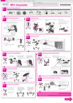
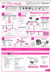
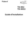
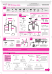
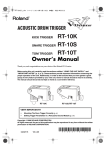
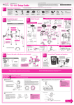
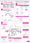
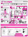
Roland, V-Drums, V-TOUR, V-CYMBALS, and V-HI-HAT are registered trademarks of Roland Corporation in the United States and/or other countries. Copyright © 2010 ROLAND CORPORATION All rights reserved. No part of this publication may be reproduced in any form without the written permission of ROLAND CORPORATION. Setup Guide * 5 1 0 0 0 1 7 0 4 8 - 0 1 As soon as you open the package, check to see that all items are included. If anything is missing, please contact your dealer. Check the included items 01 Before using this unit, carefully read the sections entitled: “USING THE UNIT SAFELY” and “IMPORTANT NOTES.” These sections provide important information concerning the proper operation of the unit. Additionally, in order to feel assured that you have gained a good grasp of every feature provided by your new unit, Owner’s manual should be read in its entirety. The manual should be saved and kept on hand as a convenient reference. * Use a commercially available kick pedal. TD-9KX2 parts Stand Cable tie x 6 AC adaptor Connection cable (special for TD-9) Drum key Stand (MDS-9) Hi-hat mount Assemble the stand 02 1. Loosen the hand knobs (A, two locations) and spread open the left and right legs of the stand as shown in the illustration. 2. Loosen the hand knob of the snare pipe (B), and pull out the snare pipe toward the side of the performer. Attach the parts 03 Assembly procedure V-Cymbal for crash V-Cymbal for ride (CY-12C) (CY-13R) V-Hi-hat (VH-11) Kick pad (KD-9) Owner’s Manual Cymbal mount x2 V-Pad for snare (PD-105) Percussion sound module (TD-9) Attach the crash cymbal (CY-12C) and ride cymbal (CY-13R) Tighten the bolt with a drum key. * The parts required for mounting the cymbals and the hi-hat are included in the TD-9KX2 attachment box. Stopper Clutch screw Felt washer Attach the snare (PD-105) and toms (PD-85) CY-13R CY-12C Hi-hat clutch 4. Attach the cymbal mounts (D, two locations) as shown in the illustration. Wing nut Tighten the wing nut to obtain an appropriate amount of sway. Attach the stopper so that the bolt is on the right-hand side, from the performer’s perspective. Attach the hi-hat (VH-11) 3. Adjust the pad mounts (C, four locations) as shown in the illustration. V-Pad for tom (PD-85 x 3) Drum key Manual set Setup Guide (this document) Quick Start Owner’s Manual Hi-hat “Roland” logo on the farther side VH-11 Motion sensor unit D: Cymbal mounts PD-85 PD-85 Tighten Tighten Loosen Loosen CONTROL OUT jack on the farther side Rod Insulating plate C: Pad mounts TD-9 Sponge side up Rod PD-85 PD-105 Adjusting the tension Check to make sure that the cymbal rod has been tightened sufficiently 6 You do not need to attach the hi-hat mount. KD-9 4 1 2 3 Tuning bolt Gap Washer 5 Hoop 1. Finger-tighten all six of the tuning bolts in the sequence shown in the illustration. 2. The appropriate amount of tension is one that will provide approximately the same striking response as on an acoustic drum. Compatible Stand A: Hand knobs B: Snare pipe If the stand wobbles, loosen this hand knob and adjust the height. 3. Use the drum key to adjust the tension as needed. Diameter: 6.0–7.0 mm (0.236"–0.276") * Adjust the position at which the TD-9 is attached so it doesn’t make contact with the VH-11. 135˚ 135˚ 1.2 m * Use a commercially available hi-hat stand. * Do not spread open the stand farther than 135 degrees as shown in the illustration. Nor should you spread the stand wider than 1.2 meters (48 inches). 04 Connect the pads to the sound module * To prevent the inadvertent disruption of power to your unit (should the plug be pulled out accidentally), and to avoid applying undue stress to the AC adaptor jack, anchor the power cord using the cord hook, as shown in the illustration. RD RDB T2 T1 3. Connect the AC adaptor, and fasten it to the cable hook as shown in the illustration to prevent it from being accidentally unplugged. RDB plug * To prevent malfunction and/or damage to speakers or other devices, always turn down the volume, and turn off the power on all devices before making any connections. HH Amplified speakers, etc. SNR RD plug 05 Connect the AC adaptor and speakers HHC TD-9 * Insert the plug firmly, making sure it’s all the way in. 2. Labels indicating the pad to be connected are attached to the cable. Make connections as shown in the illustration. ” so that they do CR1 T3 1. Connect the cable to the TD-9 as shown in the illustration. Insert the connector all the way, then turn the knobs to fasten it securely. Install the kick pedal securely. * Use cable ties to fasten the cables at the circled locations “ not interfere with your performance. Make sure to wrap the cable ties around the pipes. Connection procedure Knob Attach the kick pedal (KD-9) Attach the sound module (TD-9) Diameter: 11.7 mm (1/2") Max. Stereo headphones 1/4” plug (mono) BOW/EDGE OUTPUT jack KIK BELL OUTPUT jack CONTROL OUT jack TRIGGER OUT jack HHC plug HH plug AC adaptor (indicator) Stereo 1/4" plug This completes assembly and connections. to AC outlet Power cord As seen from the front ■■ To learn about the TD-9’s wide range of unique functionality, refer to “Quick Start.” ■■ If you need further information regarding the set up of TD-9K2, refer to the section “If you don’t hear any sound in the Owner’s Manual. Detailed explanation of each part ■■ VH-11 (Hi-hat) * Use a commercially available hi-hat stand. If you’re using the VH-11 V-hi-hat, execute the offset adjustment from the TD-9 after making connections. This adjustment is required in order to correctly detect open, close, and pedal operations. 01 Adjusting the offset. 1. Loosen the clutch screw and let the hi-hat rest naturally on the motion sensor unit. 2. Press the [SETUP]-[F1] (TRIG) button. 5. While you watch the meter that’s displayed in the right side of the screen, turn the VH-11’s VH offset adjustment screw to adjust it. Adjust the screw so that the black appears in the meter. 1. Adjust the gap between the metal portion in the center of the lower hi-hat and the sensor’s center tip to a clearance of approximately 3 mm, then tighten the clutch screw. The “TRIGGER TYPE” screen will appear. 3. Use the [CURSOR] button to move the cursor to “H” (HI-HAT). Fixing the cables 02 Adjusting the hi-hat. VH offset adjustment screw 3mm Wind the cable tie once * Although the gap can be adjusted to a clearance that makes playing the hi-hat easier, setting too narrow or wide a gap can cause improper function of the unit and prevent the hi-hat from sounding as you intend. Setting the gap to 3 mm provides the most natural feel when playing the VH-11. 4. Press the [F3] (ADVNCD)-[F3] (HI-HAT) button. The following screen will appear. OPEN CLOSE Tighten it not to slip Leave some slack in the cables Turn back to fix the cables 2. Change the spring tension by adjusting the hi-hat stand. * The tension may not be adjustable on some stands. NOTE * When performing, make sure that the name “Roland” on the hi-hat is on the opposite side of the stand from the hi-hat pedal. If the closed hi-hat sound is difficult to attain, rotate the VH offset adjustment screw towards “CLOSE.” If the open hi-hat sound is difficult to attain, rotate the screw towards “OPEN.” * If the sound cuts off when you strike the hi-hat forcefully, rotate the VH Offset adjustment screw towards “OPEN.” NOTE * Continuous playing may cause dis-coloration of the pad, but this will not affect the Pad’s function. * If the hi-hat clutch has been detached from the hi-hat, refer to “If the Clutch Was Apart from the Hi-Hat” in the owner’s manual. Other side * Detailed explanation of each part ■■ KD-9 (Kick) * Use a commercially available kick pedal. Attach the kick pedal 01 ■■ CY-12C (Crash) on the kick pedal and make sure 02 Step that it’s properly attached and in a stable When Using a Twin Pedal Position the beater so that it strikes the center of the head, then secure the kick pedal and KD-9 firmly in place. Beater Bell * Depending on how you’re using the unit, the bolts that attach the pedal to the plate could become loose, causing the pedal to rattle during performance. In such cases, use commercially available tools to tighten the bolts. Bolt Base Pad face Bow Bow Edge Edge BOW/EDGE OUTPUT jack BOW/EDGE OUTPUT jack Secure the cable in place with the cable tie BELL OUTPUT jack Be sure to make this small plastic Wind a cable tie hook visible around the pipe from you. and tighten it in order to not to slip. KD-9 component names NOTE * Install the kick pedal securely. * Take care not to pinch your fingers. When using the kick pedal on a carpet or on a drum mat (TDM series), the slip-prevention tape that’s on the base should prevent the KD-9 from moving around. However, if that’s not enough to keep the KD-9 in a fixed position, you can adjust When using on the floor things so that the tips of the anchor bolts protrude through the base. That should keep it in place and make it easier for you to play. Fixing the cables (CY-12C/CY-13R) Leave some slack in the cable Check to be sure they’re making contact with the floor When using on the carpet or drum mat CY-13R component names Pad face Check to make sure that the base of the KD-9 and the kick pedal both make contact with the floor. Install the kick pedal securely. 03 Adjusting the Anchor Bolts CY-12C component names position. Position the two beaters equally apart from the center of the pad as shown in the figure at left. If one of the beater is further away from the center than the other, the sound from the further beater will be lower in volume, or will not sound as desired. Using a twin pedal will result in lower sensitivity as compared to when a single pedal is used. Raise the sensitivity on the sound module. For details, see “Editing the pad settings [F2] (BASIC)” in the owner’s manual. ■■ CY-13R (Ride) Wind a cable tie around a cable. * When used on flooring, the anchor bolts may damage the floor. * The tips of the anchor bolts are sharp. Handle with care. Head OUTPUT jack Insert the small plastic hook to a hole to secure the cable to the cymbal arm. Anchor bolts Slip-prevention tape NOTE Mounting plate for the kick pedal * Continuous playing may cause dis-coloration of the pad, but this will not affect the Pad’s function. Base ■■ PD-85 (Tom) ■■ PD-105 (Snare) Head replacement procedure NOTE PD-85 component names * Be sure to adjust the head tension of the PD-85 / PD-105 before use. PD-105 component names Sensor Hoop (Rim) * Striking the head when the head tension is loose may damage the sensor and head. Hoop (Rim) Head Tuning bolts Wing nut Head Lugs Washer Wing bolt Bracket Tuning bolt OUTPUT jack Shell The head is an expendable item that eventually will wear out and need to be replaced. Replace the head when the following occurs: Slack portions remain in the head even when the head tension is properly adjusted. OUTPUT jack * To obtain replacement heads, please contact the nearest Roland Service Center or an authorized Roland distributor, as listed in “Information.” Loosen * Do not apply excessive force to the sensor located below the center of the head of the PD-85/PD-105. Doing so can interfere with accurate detection, and may damage it. * Due to the nature of the materials used in the sensor of the PD-85/ PD-105, changes in room temperature may affect the sensitivity of the sensor. Drum key Hoop’s rubber portion Washer * The rubber portion of the hoop is a consumable item that will undergo wear with use over time, depending on the number and strength of rim shots. Playing rim shots on the worn rubber portion may cause malfunctions. If this occurs, the hoop rubber should be replaced. Please contact Roland customer service regarding replacement of the hoop rubber. CAUTION Notices Used for instructions intended to alert the user to the risk of death or severe injury should the unit be used improperly. Used for instructions intended to alert the user to the risk of injury or material damage should the unit be used improperly. * Material damage refers to damage or other adverse effects caused with respect to the home and all its furnishings, as well to domestic animals or pets. Placement About the Symbols The symbol alerts the user to important instructions or warnings.The specific meaning of the symbol is determined by the design contained within the triangle. In the case of the symbol at left, it is used for general cautions, warnings, or alerts to danger. The symbol alerts the user to items that must never be carried out (are forbidden). The specific thing that must not be done is indicated by the design contained within the circle. In the case of the symbol at left, it means that the unit must never be disassembled. The symbol alerts the user to things that must be carried out. The specific thing that must be done is indicated by the design contained within the circle. In the case of the symbol at left, it means that the power-cord plug must be unplugged from the outlet. • Do not expose the unit to direct sunlight, place were struck during product testing. This does not af- temperature extremes. Excessive heat can deform or fect the performance or functionality of the product, discolor the unit. and you may continue using it with confidence. droplets (condensation) may form inside the unit. Damage or malfunction may result if you attempt to use the unit in this condition. Therefore, before using until the condensation has completely evaporated. WARNING • Do not allow rubber, vinyl, or similar materials to remain on this unit for long periods of time. Such • Do not open or perform any internal modifications on the unit. • Do not place containers containing liquid on this product. Never allow foreign objects (e.g., flammable objects, coins, wires) or liquids (e.g., water or • Do not attempt to repair the unit, or juice) to enter this product. Doing replace parts within it (except when this so may cause short circuits, faulty manual provides specific instructions operation, or other malfunctions. directing you to do so). Please consult an authorized Roland distributor or the • In households with small children, an nearest Roland Service Center; a list adult should provide supervision until of these can be found in the owner’s the child is capable of following all the manual for the device to which you are rules essential for the safe operation of connecting. the unit. • Never install the unit in any of the following locations. • Protect the unit from strong impact. the finish. Maintenance • For everyday cleaning wipe the unit with a soft, dry cloth or one that has been slightly dampened with water. To remove stubborn dirt, use a cloth impregnated with a mild, non-abrasive detergent. CAUTION • Try to prevent cords and cables from • Use a reasonable amount of care when using the • When connecting / disconnecting all cables, grasp way you will avoid causing shorts, or damage to the cable’s internal elements. • Exposed to rain; or are • Never climb on top of, nor place heavy objects on the unit. and shakiness. • Should you remove nuts, washers, screws, anchor bolts, etc., keep them mended by Roland. in a safe place out of children’s reach, so there is no chance of them being • To avoid disturbing your neighbors, try to keep equipment from falling over. • Do not remove the special VH-11 clutch from the hi-hat or disassemble the clutch. • When not using the hi-hat for extended periods, store the hi-hat in the open position to prevent placing any stress on the motion sensor unit. • High-precision sensors are located at the portion of the motion sensor unit indicated by the arrow in the left figure below. Take care not to subject this area to excessive shock, and do not allow any foreign objects For China to enter any gaps. • Over long periods of use, the portion of the motion sensor unit that comes into contact with the hi-hat (the damper) may become worn at the points indicated by the arrows in the right figure above. Such damper wear may prevent proper adjustment the damper. For more information on replacing the damper, contact Roland Service. • In the interest of product improvement, the specifications and/or appearance of this unit are subject to change without prior notice. the unit’s volume at reasonable levels. You may swallowed accidentally. concerned about those around you. • This instrument is designed to minimize the extraneous sounds produced when it’s played. However, since sound vibrations can be transmitted through floors and walls to a greater degree than expected, take care not to allow these sounds to become a nuisance to neighbors, especially when using headphones. • When you need to transport the unit, package it you still need to make sure that any in the box (including padding) that it came in, if location you choose for placing the possible. Otherwise, you will need to use equivalent unit provides a level surface that will packaging materials. from wobbling. the tripod are opened wide enough to keep the prefer to use headphones, so you do not need to be a stand (MDS series) that is recom- properly support the unit, and keep it When installing the hi-hat, make sure the legs of with an unnatural motion. If this occurs, replace out of the reach of children. stable. If not using a stand (MDS series), • The hi-hat stand is supported by means of a tripod. tions. • Humid; or are placed so it is level and sure to remain pad, but this will not affect the Pad’s function. of the offset and may cause the hi-hat to swing the connector itself—never pull on the cable. This stand (MDS series) must be carefully • Continuous playing may cause dis-coloration of the output jacks. Rough handling can lead to malfunc- and cables should be placed so they are series) recommended by Roland, the For EU Countries • Never use benzine, thinners, alcohol or solvents of • Subject to salt exposure; or are • When using the unit with a stand (MDS If a lock bushing comes out of the frame while you’re replacing the head, align the lock bushing’s slots with the “+” shaped portion of the frame, and press it firmly into the frame. As routine maintenance, you should wipe the striking becoming entangled. Also, all cords • This unit should be used only with Lock bushing (KD-9) • Exposed to steam or smoke; or are • Subject to high levels of vibration 7. Adjust the head tension. For details, refer to the explanation on the opposite side of this leaflet. a soft, dry cloth. Additional Precautions • Damp (e.g., baths, washrooms, on • Dusty or sandy; or are 6. Pass the washers over the tuning bolts, and attach them to the hoop and frame. Afterwards, be sure to wipe the unit thoroughly with or deformation. vehicle, near a heating duct, on top wet floors); or are objects can discolor or otherwise harmfully affect any kind, to avoid the possibility of discoloration and/ (Do not drop it!) (e.g., direct sunlight in an enclosed or are Frame 5. Place the hoop on the head. surface using a dry, soft cloth. • Subject to temperature extremes of heat-generating equipment); Lock bushing 4. Place the new head on the frame. the passage of time, this preservative may appear on the surface as a white stain, or reveal how the pads the unit, you must allow it to stand for several hours, ALWAYS OBSERVE THE FOLLOWING WARNING Hoop with a preservative to maintain its performance. With an enclosed vehicle, or otherwise subject it to temperature and/or humidity is very different, water 2. Remove the hoop. • The rubber portion of the striking surface is treated it near devices that radiate heat, leave it inside • When moved from one location to another where the * The lock bushing is a part that prevents vibration of the hoop from turning and loosening the tuning bolts when you play rim shots. 3. Remove the old head. Frame IMPORTANT NOTES WARNING and Tuning bolt Frame Frame 1. Remove all tuning bolts and washers. * While you remove the tuning bolts, press your finger against the lock bushing so that it does not come out of the frame. Holder About Tighten • Some connection cables contain resistors. Do not use cables that incorporate resistors for connecting to this unit. The use of such cables can cause the sound level to be extremely low, or impossible to hear. For information on cable specifications, contact the manufacturer of the cable. For C.A. US (Proposition 65) WARNING This product contains chemicals known to cause cancer, birth defects and other reproductive harm, including lead.