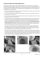
1
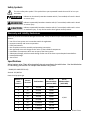
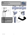
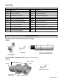
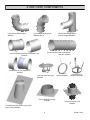
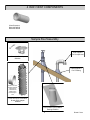
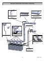
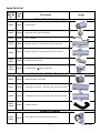
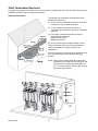
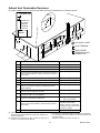
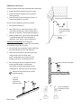
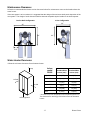
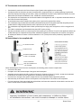
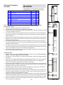
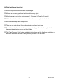
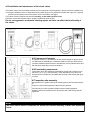
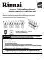
Common Vent Installation Manual For the RU98i (REU-KB3237FFUD-US) Condensing Water Heater This manual is a supplement to the appliance manual. Additional information can be obtained from the Rinnai water heater manual. The exhaust vent system, CVent, is supplied by Ubbink. Certified to ANS Z21.10.3 - CSA 4.3 Only for U.S. installations WARNING If the information in these instructions is not followed exactly, a fire or explosion may result causing property damage, personal injury or death. — Do not store or use gasoline or other flammable vapors and liquids in the vicinity of this or any other appliance. — WHAT TO DO IF YOU SMELL GAS Do not try to light any appliance. Do not touch any electrical switch; do not use any phone in your building. Immediately call your gas supplier from a neighbor’s phone. Follow the gas supplier’s instructions. If you cannot reach your gas supplier, call the fire department. — Installation and service must be performed by a licensed professional. This entire manual must be left for the consumer. The consumer must read and refer to this manual for proper operation and maintenance of the common vent system. 1 Rinnai CVent Table of Contents Installer Qualifications .......................................... 2 Venting Guidelines .............................................. 12 Description ............................................................ 2 Maximum Equivalent Vent Length ...................... 13 Model Applicability ............................................... 2 CVent Termination Clearances............................ 14 Safety Symbols ...................................................... 3 Exhaust Vent Termination Clearances ................ 15 Warranty and Liability Exclusions ......................... 3 CVent Maintenance Clearances .......................... 17 Specifications ........................................................ 3 Water Heater Clearances .................................... 17 High Altitude Installation ...................................... 4 CVent Installation Instructions ............................ 18 Water Heater Installation ..................................... 4 Common Header Check valve Maintenance ....... 23 Parts/Kits............................................................... 5 Final Checklist...................................................... 24 Sample Roof Installation ....................................... 9 Appendix Sample Horizontal Termination Installation………. 10 Ubbink CVent Assembly Instructions .................. 25 Spare Parts List………………………………………………….11 Installer Qualifications installation of the vent system and components, or failure to follow all installation WARNING Improper instructions, can result in serious injury. A licensed professional must install the common venting. If you lack these skills, contact a licensed professional. The installer should have skills such as connecting gas lines, water lines, valves, and electricity knowledge of applicable national, state, and local codes Description The CVent Common Venting system provides longer vent lengths and fewer wall or roof penetrations than conventional single-unit venting. For the exhaust flue, CVent utilizes a CSA-certified and tested polypropylene venting material from Ubbink, the same supplier for Rinnai's innovative line of concentric venting. The various sections are self locking and sealing and can be pushed together without use of cement or glue. CVent is only for use in U.S. installations and is not currently approved for use in Canada. Installation is certified for up to 10,200 feet. Refer to the installation / operations manual for the tankless engine (RU98) for appropriate dip switch selection. Refer to High Altitude Installation section for appropriate de-rate values. Model Applicability The common vent system is CSA certified (ANSI Z21.10.3, Gas Water Heaters Standards) for use only with the Rinnai tankless condensing water heater RU98i (REU-KB3237FFUD-US). Rinnai CVent 2 Safety Symbols This is the safety alert symbol. This symbol alerts you to potential hazards that can kill or hurt you and others. DANGER Indicates an imminently hazardous situation which, if not avoided, will result in death or serious injury. WARNING Indicates a potentially hazardous situation which, if not avoided, could result in death or serious injury. CAUTION Indicates a potentially hazardous situation which, if not avoided, could result in minor or moderate injury. It may also be used to alert against unsafe practices. Warranty and Liability Exclusions Claims for personal and material damages are excluded, if they are due to any or several of the following reasons: • Use of the Cvent system not in accordance with the regulations. • Improper assembly and incorrect operation. • Faulty maintenance. • Non-compliance with the assembly and operating instructions. • Non-approved structural changes to the unit or to the individual components. • Installation of components which are not part of the Cvent system . • Subsequent damage, which occurred through further use of the Cvent system despite known defects. • Intentional damage. • Acts of God. Specifications Water heaters using CVent will automatically de-rate according to the table below. Use the table below for calculating your total Btu for multiple water heaters using CVent. * RU98i (REU-KB3237FFUD-US) Altitude: 0-2,000 feet Natural and propane gas Number of water heaters* Percent De-rated Total Btu Rate Btu at Minimum Rate (without MSB) 1 0% 199,000 15,200 2 1% 394,000 30,400 3 1.5% 588,000 45,600 4 2% 780,000 60,800 5 2.5% 970,000 76,000 6 3% 1,158,000 91,200 7 3.5% 1,344,000 106,400 8 4% 1,528,000 121,600 3 Btu at Minimum Rate (with MSB) 15,200 Rinnai CVent High Altitude Installations The Rinnai RU98i (REU-KB3237FFUD-US) has been certified for use with the CVent Common Exhaust Vent System at high altitude installations up to 10,200 feet. (3,109 m). The common vent system is CSA certified (ANSI Z21.10.3, Gas Water Heaters Standards) for use only with the Rinnai tankless condensing water heater RU98i (REU-KB3237FFUD-US). For CVent installations at altitude you must ensure that the water heaters are properly installed and setup for the altitude that they will be operating at. (For information on how to adjust altitude settings reference the installation/ operations manual for the RU98i (REU-KB3237FFUD-US) tankless water heater) Water heaters using CVent at altitudes over 2,000ft will automatically de-rate according to the table below. Use the tables below for calculating your total Btu for multiple water heaters using CVent at elevation: * RU98i (REU-KB3237FFUD-US) Altitude: 2,001-10,200 feet Natural and propane gas High Altitude De-Rate plus Cvent De-Rate - Natural Gas Number of Water Heaters 2001-5200 Ft 5201 - 7700 Ft 7701 - 10200 Ft 1 170,000 153,000 139,000 2 336,600 302,940 275,220 3 499,800 449,820 408,660 4 659,600 593,640 539,320 5 816,000 734,400 667,200 6 969,000 872,100 792,300 7 1,118,600 1,006,740 914,620 8 1,264,800 1,138,320 1,034,160 High Altitude De-Rate plus Cvent De-Rate - LP Gas Number of Water Heaters 2001-5200 Ft 5201 - 7700 Ft 7701 - 10200 Ft 1 168,000 151,000 120,000 2 332,640 298,980 237,600 3 493,920 443,940 352,800 4 651,840 585,880 465,600 5 806,400 724,800 576,000 6 957,600 860,700 684,000 7 1,105,440 993,580 789,600 8 1,249,920 1,123,440 892,800 Water Heater Installation For information regarding the installation of the RU98i (REU-KB3237FFUD-US) tankless water heater, please reference the installation operations manual included with the tankless unit. Set the water heater for “Long Vent” by adjusting the # 1 switch to the OFF Position. (Must be done on all tankless heaters when using CVent System) 4 Rinnai CVent CVent Starter Kit 790005 8-Inch For Back–2-Back or InLine Combustion Air & Exhaust 1 2 NO Qty. 1 3 Qty. 1 5 QTY DESCRIPTION CVENT ENDPIECE (EXHAUST) W/ CLEANOUT & CONDEN1 SATE DRAIN (32mm) 1 2 1 CVENT COMB AIR ENDPIECE D8 3 1 CVENT CONDENSATE TRAP (32mm Connection) 4 1 CVENT DRAIN HOSE 5 2 CVENT DRAIN HOSE CLAMP 6 1 UBBINK INSTALLATION INSTRUCTION 7 1 CENTROCERIN LUBRICANT Qty. 1 Qty. 1 4 Qty. 2 7 CVent InLine Kit 790007 8-Inch Header Kit For InLine Combustion Air & Exhaust 1 5 Qty. 1 Qty. 1 Ø4” Ø3” Qty. 1 2 4 Qty. 1 NO QTY DESCRIPTION 1 1 CVENT COLLECTOR, 1 CONNECTION, D8 X L20 X D4 (Exhaust) 2 1 CVENT ELBOW D4 X 87° WITH CLEANOUT 3 1 CVENT EXTENTION, D4 X L18 4 1 CVENT APPLIANCE ADAPTER, CHECK VALVE AND HOSE TRAP 5 1 CVENT COMB. AIR COLLECTOR, 1 CONNECTION, D8 X L20 X D3 6 1 CVENT COMB AIR FLEX FITTING, D3 7 1 CENTROCERIN LUBRICANT 3 6 Qty. 1 Qty. 1 7 5 Rinnai CVent CVent Back-2-Back Kit 790008 8-Inch Header Kit For Back-2-Back Combustion Air & Exhaust 1 Qty. 1 5 Ø4” Qty. 1 Ø3” Ø4” Qty. 2 Qty. 2 2 3 NO QTY 1 1 CVENT COLLECTOR, 2 CONNECTION, D8 X L20 2 2 CVENT ELBOW D4 X 87° WITH CLEANOUT 3 2 4 2 5 1 CVENT EXTENSION, D4 X L18 CVENT APPLIANCE ADAPTER WITH CHECK VALVE AND TRAP CVENT COMB. AIR COLLECTOR, 2 CONNECTION, D8 X L20 X D3 6 2 CVENT COMB. AIR FLEX FITTING, D3 7 1 CENTROCERIN LUBRICANT 4 6 Qty. 2 DESCRIPTION Rinnai CVent 7 6 Ø3” Qty. 2 Parts / Kits CVent Common Venting Exhaust / Intake Components (PPtl, polypropylene translucent) Part No. Description Part No. Description 790005 CVent 8-in Starter Kit 790024 CVent 8-in Brackets 790007 CVent 8-in InLine Kit 790025 Centrocerin lubricant 790008 CVent 8-in Back-2-Back Kit 790035 CVent Extension, D4 x L18 790001 CVent 8-in Roof Termination Kit 790028 CVent Extension, D4 x L39 790002 CVent 8-in Flat Roof Flashing 790029 CVent Elbow D8 x 90 degree Vertical Support 790003 CVent 8-in Pitched Roof Flashing 790030 CVent 8-in Chase Cover 790004 CVent 8-in Wall Termination Kit 790031 CVent 8-in Vent Distancer, stainless steel 790020 CVent Extension, D8 x L18 790034 CVent 8-in Vent Rain Cap 790021 CVent Extension, D8 x L39 790032 Inverter Coupling Kit with condensate trap 790022 CVent Elbow D8 x 45degree (2 in a box) 790037 Combustion Air PVC Adapter Kit 790023 CVent Elbow D8 x 90degree Termination Kits Cvent 8-in Roof Termination Kit with PVC adapter 790001 PP-PVC Adapter Centrocerin Lubricant (For Combustion Air PVC transition) CVent 8-in Roof Termination (Outer shell: Stainless Steel) Cvent 8-in Wall Termination Kit (Combustion Air & Exhaust) 790004 Ø0.24” (Qty. 4) Ø7.89” 31” Ø12.2” Centrocerin lubricant Interior Slip Fit Wall Plate (Material: Stainless Steel) 7 Rinnai CVent 8 INCH VENT COMPONENTS CVent Elbow D8x90 degree #790023 CVent Elbow D8x45 degree #790022 (Qty.2) CVent Elbow D8x90 degree Vertical Support #790029 CVent Extension D8xL18” #790020, D8xL39” #790021 Inverter Coupeling Kit With Condensate Trap #790032 Combustion Air PVC Adapter Kit #790037 CVent 8in Vent Rain Cap #790034 CVent Flat Roof Flashing #790002 CVent 8-in Bracket #790024 CVent 8in Vent Distancer #790031 CVent 8-in Chase Cover #790030 CVent Pitched Roof Flashing (Including Storm Collar) #790003 8 Rinnai CVent 4 INCH VENT COMPONENTS CVent Extension D4xL18 #790035 D4xL39 #790028 Sample Roof Assembly O TI P O L NA Field Supplied PVC Components CVent 8-in Rain Cap #790034 Field Supplied 8” PVC Flashing NOTE: Use PVC adapter (illustrate above) at the combustion air header when transitioning to PVC CVent 8-in Roof Termination Kit with PVC Adapter #790001 Cvent pitched roof moldable flashing #790003 9 Rinnai CVent Sample Horizontal Termination Assembly Part Number:790027 CVent Elbow D4 x 90 (Qty. 2) Part Number:790020 / 790021 CVent Extension (Qty. 5) Part Number:790004 Wall Termination Kit Combustion Air & Exhaust (Qty 2) Field Supplied PVC Components Part Number: 790005 CVent Starter Kit (Qty. 1) Part Number: 790008 CVent Back-2-Back Kit (QTY. 4) Part Number:790037 Combustion Air PVC Adapter Kit (Qty. 1) Field Supplied PVC Components 10 Rinnai CVent Spare Parts List Included With Kit No. Part No. Description Image Exhaust Vent Components Ø8 790005 790042 CVent Endpiece 790005 790048 Condensate Trap (32mm Connection) 790005 790049 Hose + 2 Clamps 790007 790040 Exhaust Collector, 1 connection, D8 x L20, D4 connection Ø8 Ø4 Ø4 790008 790041 Exhaust Collector, 2 connections, D8 x L20, D4 connection Ø8 Ø4 Ø4 790007 790008 790035 CVent Extension, D4 x L18 790007 790008 790039 CVent Elbow D4 x 87degree with cleanout Ø4 Combustion Air Vent Components Ø8 790005 780046 Intake/Combustion Air Endpiece 790007 780044 Combustion Air Collector, 1 connection, D8 x L20, D3 connection Ø8 Ø3 Ø3 790008 780045 Combustion Air Collector, 2 connection, D8 x L20, D3 connection Ø8 Ø3 790007 790008 Ø3 Ø3 780050 CVent flex Line D3 Appliance Adapter Ø4 790007, 790008 790038 CVent Appliance and Check Valve & hose (new!) Ø3 11 Rinnai CVent Venting Guidelines WARNING The Ubbink Polypropylene CVent can be used on both the combustion air and exhaust. Field supplied PVC material can only be used on the combustion air side and MUST NOT be used for the exhaust. DO NOT Do not install in separate distribution systems. All water heaters common vented must be in the same hot and cold plumbing manifolds and must not exceed 8 units. Do not use PVC, CPVC, ABS or galvanized material for the exhaust vent. CVent must be used on the Support horizontal vent runs a minimum of every four feet and all vertical vent runs a minimum of every six feet. Venting should be as direct as possible with a minimum number of pipe fittings. Vent connections must be firmly pressed together so that the gaskets form an air tight seal. Install an appliance adapter which contains a check valve onto each water heater. Use only the check valve specified in this manual. Do not attempt to build your own system. The air intake appliance adapter connected to the water heater must be secured with one selftapping screw. Check and clean the header check valve every 12 months according to the maintenance instructions in this manual. Set the temperature setting on all water heaters being common vented to the same temperature. INFORMATION Unless recovering a tank, Rinnai recommends installing an MSB controller when common venting and where water heaters are in a manifold system. For assembly details, refer to the Ubbink Installation and Assembly Instructions located in the appendix of this manual. Rinnai recommends replacing the check valve when replacing the water heater. exhaust. Do not combine vent components from different manufacturers. Vent diameter must not be reduced. Do not connect the venting system with an existing vent or chimney. Do not common vent with the vent pipe of any other type of water heater or appliance. Do not install the water heater in an area of negative pressure. Do not install the water heater, venting, and vent termination(s) in any areas where the air may contain corrosive compounds. MUST DO • The water heater dip switch setting must always be set to long vent (#1 in set of tan switches set to OFF). This water heater is a direct vent water heater and therefore is certified and listed with the vent system. You must use vent components that are certified and listed with the water heater model. The vent system must vent directly to the outside of the building and use outside air for combustion. Avoid dips or sags in horizontal vent runs by installing supports per the vent manufacturer’s instructions. Rinnai CVent 12 Maximum Equivalent Vent Length In the table below you find the maximum equivalent pipe length of the exhaust and intake venting. When determining equivalent exhaust and intake vent lengths add: • • • 6 feet for each 90° elbow 3 feet for each 45° elbow • Minimum Equivalent Vent Length Add any vent extension lengths which are added within the header due to increased spacing of the water heaters Header kits have already been counted and do not need to be added. Maximum Equivalent Vent Length Number of water heaters Exhaust* Intake* Exhaust* Intake* 1 to 7 5 ft 15 ft 100 ft 100 ft 8 5 ft 15 ft 41 ft 41 ft *Approved exhaust and intake diameter is 8 inches. CVent Termination Clearances Vertical Termination There should be a minimum of 36 inches between exhaust terminations in multiple common vent installations. Clearances of Brackets All supports such as wall brackets on the external façade or spacer blocks in a shaft must be assembled in a maximum distance of 78 in (2 m). Where there is a bend, additional spacer blocks or wall brackets can be planned before and after the bend, depending on the local situation. 36” MINIMUM INSIDE EDGE TO INSIDE EDGE Freestanding Components 12” OVER MAX. SNOW LEVEL OR 24” WHICHEVER IS GREATER EXHAUST - CVent Components, which are assembled freestanding vertical (roof termination) with a length of more than 59 in (1.5 m), must, depending on the amount of wind and snow level expected, be additionally secured to the building with guys or braces. INTAKE - PVC 13 Rinnai CVent CVent Termination Clearances This appliance along with the CVent Common Vent System is certified with the Cvent 8-in Wall Termination Kit, (790004) mounted in the orientation shown below. Horizontal Termination The exhaust and combustion air terminations must follow these clearances: [1] 12 inch minimum vertically from bottom of exhaust termination to top of intake termination. [2] 12 inch minimum vertically from bottom of combustion air termination to ground or anticipated snow line. [3] From edge of exhaust termination to edge of combustion air termination: Minimum of 36 inches Maximum of 20 feet [4] 36 inch minimum from multiple exhaust CVents There should be a minimum of 36 inches between exhaust terminations in multiple common vent installations. Combustion Air Vent Vertically Combustion Air Vent Vertically The vent (exhaust & combustion air) terminations must be in the same pressure zone and face the same direction. NOTE: During colder weather when the exhaust temperature is much hotter than the outside air, the exhaust fumes condense producing water vapor. As a result a plume of water vapor may be seen leaving the exhaust. EXHAUST VENT MAXIMUM 20’ MINIMUM 36” COMBUSTION AIR VENT Rinnai CVent 14 Exhaust Vent Termination Clearances For indoor models, you must install terminations to bring in combustion air and expel exhaust. TERMINATION INSIDE CORNERDETAIL G Clearance in Ref. A also applies to anticipated snow line H A SNOW I B D M FIXED CLOSED B K OPERABLE E C B B FIXED CLOSED J B A OPERABLE X AIR SUPPLY INLET V VENT TERMINAL L AREA WHERE TERMINAL IS NOT PERMITTTED F B Ref US Installations Description A Clearance above grade, veranda, porch, deck, or balcony 12 inches (30 cm) B Clearance to window or door that may be opened 12 inches (30 cm) C Clearance to permanently closed window * D Vertical clearance to ventilated soffit, located above the terminal within a horizontal distance of 2 feet (61 cm) from the center line of the terminal * E Clearance to unventilated soffit * F Clearance to outside corner * G Clearance to inside corner * H Clearance to each side of center line extended above meter/ regulator assembly * I Clearance to service regulator vent outlet * J Clearance to nonmechanical air supply inlet to building or the combustion air inlet to any other appliance K Clearance to a mechanical air supply inlet 3 feet (91 cm) above if within 10 feet (3 m) horizontally L Clearance above paved sidewalk or paved driveway located on public property M Clearance under veranda, porch, deck, or balcony [1] A vent shall not terminate directly above a sidewalk or paved driveway that is located between two single family dwellings and serves both dwellings. 12 inches (30 cm) Refer to local code for horizontal termination above a public walkway, driveway, or area where condensate or vapor could create a nuisance or hazard. * For clearances not specified in ANSI Z223.1/NFPA 54, clearances are in accordance with local installation codes and the requirements of the gas supplier. [2] Permitted only if veranda, porch, deck, or balcony is fully open on a minimum of two sides beneath the floor. Clearance to opposite wall is 24 inches (60 cm). 15 Rinnai CVent Additional clearances Check on whether local codes supersede these clearances. Avoid termination locations near a dryer vent. Avoid termination locations near commercial cooking exhaust. You must install a vent termination at least 12 (0.61 m ) to an inside corner inches above grade or snow line. 24" The vent for this appliance shall not terminate • • • Over public walkways; or 36" Near soffit vents or crawl space vents or other area where condensate or vapor could create a nuisance or hazard or cause property damage; or (0.91 m) between terminals at same level Where condensate or vapor could cause damage or could be detrimental to the operation of regulators, relief valves, or other equipment. INSIDE CORNER Important considerations for locating vent termination under a soffit (ventilated or unventilated or eave vent; or to a deck or porch) Do not install vent termination under a soffit vent such that exhaust can enter the soffit vent Install vent termination such that exhaust and rising moisture will not collect under eaves. Discoloration to the exterior of the building could occur if installed too close. Do not install the vent termination too close 24" under the soffit where it could present recirculation of exhaust gases back into the combustion air intake part of the termination. V (0.61 m) to wall or parapet V Represents the exhaust vent of CVent common venting. (0.91 m) between terminals at different levels 60" 36” V 36” V Rinnai CVent 16 (0.91 m) between terminals at same level Maintenance Clearances Follow the recommended minimum service clearances below for maintenance access to the header above the water heater. If the vent system is to be enclosed, it is suggested that the design of the enclosure shall permit inspection of the vent system. The design of such enclosure shall be deemed acceptable by the installer or the local inspector. Back to Back Configuration In Line Configuration 30” 42” 42” 36” 5.15” Water Heater Clearances Follow the minimum clearances from the water heater. Indoor model RU98i to top to front to side to floor/ground to Combustibles inches (mm) to NonCombustibles inches (mm) Top of Heater 6 * (152) 2 *(51) Back of Heater 0 (zero) 0 (zero) Front of Heater 6 (152) 6 (152) Sides of Heater 2 (51) 1/2 (13) Ground/Bottom 12 (305) 12 (305) Vent 0 (zero) 0 (zero) * 0 inches from vent components and condensate drain line. The clearance for servicing is 24 inches in front of the water heater. 17 Rinnai CVent Installation Instructions Exhaust Vent Installation Procedures: • • • • • After ensuring the water heaters are mounted securely and spaced 20.5” apart, install the appliance adapter on top of the water heaters. hand cleanout cap Exhaust Venting is designed for a 3° rise. When the water heaters are mounted at 20.5” spacing, the height increase is 1” per water heater. A 4” diameter extension pipe is included with the kit that must be cut to length to account for the rise from unit to unit. After cutting, always deburr and bevel the end of the vent piece so the sealing gaskets are not damaged and operation of the vent system is not compromised. Install the elbows with hand cleanout cap to the 4” diameter extension pipe. Do not cut or modify the elbow. Cleanout cap should remain accessible for periodic inspection and access for service when needed. After combustion air and exhaust vent components are appropriately positioned, securely fasten the “CVent Appliance Adapter with Check Valve and Trap” to the top of the water heater with a self tapping screw. Connect the combustion air opening of the appliance adapter to one end of the flex connector and the other end of the flex connector to the Combustion Air Collector. Elbow 4” Extension Appliance Adapter Securing Screw Combustion Air Collector Exhaust Collector Flex Connector • Connect the open end of the elbow to the exhaust header. Elbow Rinnai CVent 18 Options for Combustion Air Vent: • • For extended Intake pipe runs, PVC can be used between the Intake Header and Termination. Use the PVC adapter (described below) when transitioning from the PP intake header to the stainless steel Combustion Air Termination. WARNING The materials described below can only be used on the combustion air vent. The Ubbink Polypropylene CVent can be used on both the combustion air and exhaust. Field supplied PVC material can only be used on the combustion air side and MUST NOT be used for the exhaust. Approval Codes for Installation Item Description Plastic Vent and/or combustion air components Plastic pipe cement and primer • Flue Material United States PVC Schedule 40 ANSI/ASTM D1785 PVC - DWV ANSI/ASTM D2665 CPVC Schedule 40 ANSI/ASTM F441 PVC ANSI/ASTM D2564 CPVC ANSI/ASTM F493 Combustion Air PVC Adapter Kit (Part #: 790037) includes both a transition from the 8” (200mm) PP header to 8” PVC and an 8”PVC to 8” (200mm) termination PP to PVC ADAPTER: 8” (200mm) PP header to 8” PVC PVC to TERMINATION ADAPTER: 8”PVC to 8” (200mm) termination FIELD SUPPLIED PVC PIPE Plastic pipe cement and primer • Fasten, secure, and support all vent materials using manufacturer and industry standards to avoid potential intake air leaks or blockage. Support horizontal vent runs a minimum of every 4 feet and all vertical vent runs a minimum of every 6 feet. 19 Rinnai CVent Installation Instructions Refer to the Ubbink appendix of this manual for the vent system assembly instructions. Follow these Rinnai installation instructions in this manual in addition to the Ubbink vent system assembly instructions. Install the venting according to one of the 2 configurations below. Do not locate the common vent remotely from the water heaters. The installation area should be measured to make sure that adequate space is available to install the water heaters and venting system. 3° 3” (76mm) 1” (25mm) 2” (51mm) Back to back Configuration (2 to 8 water heaters) EXHAUST AIR INTAKE 7” (178mm) 6.25” (159mm) 20.5” (520) NOTE: Dimensions above are used in all back to back configurations TYPICAL 7” (178mm) 6” (152mm) 5” (127mm) 4” (101mm) 3” (76mm) 3° 2” (51mm) 1” (25mm) In Line Configuration (2 to 8 water heaters) EXHAUST AIR INTAKE 20.5” (520) TYPICAL Note: If water heaters are mounted directly on a wall, air intake piping will need to be in front of the appliance adapters. The intake header in the drawing above has been removed for illustration purposes. Rinnai CVent 20 Installation Instructions Recommended Spacing of Water Heaters Spacing of the water heaters is critical for the common vent system to mounting easily and securely. The collectors are made for 20.5” spacing (center line to center line) between water heaters. If a different spacing is needed, please contact Rinnai concerning your application. Rinnai recommends using our Tankless Rack System (TRS) which is designed for 20.5” spacing. Our engineered system is designed to make installation simple which greatly reduces labor time and the chance of miscalculations. Custom Water Heater Spacing If common venting with LESS than 20.5” between water heaters: • • The installer assumes all responsibility of following local codes. Inspectors can reject the installation if the rating plate cannot be seen for all water heaters. D4 Extension Pieces must be cut appropriately to maintain the required 3° slope. If common venting with GREATER than 20.5” between water heaters: • The installer must purchase a vent extension cut to the appropriate length between the collectors. • The length of each additional vent extension must be considered in the maximum allowable vent length. • D4 Extension Pieces must be cut appropriately to maintain the required 3° slope. Vent extension cut to size Air Intake extension D4 Extension Piece NOTE: Never attempt to cut or modify the collectors. To maintain a 3° slope, use the following formula to calculate D4 Extension Piece length (L): (L) = (water heater spacing) X 0.05 Example: if the adjacent water heater is 20.5” away Length (L) = 20.5” x 0.05 = 1.02” Example: if the adjacent water heater is 26” away Length (L) = 26.0” x 0.05 = 1.30” 21 Rinnai CVent Installation Instructions Install the Condensate Trap and Drain Pipe The CVent exhaust header collects condensate. A collector and self-priming trap is included with each starter kit. Additional condensate trap loop assemblies are provided with each appliance adapter. Condensate loops must be primed before operation per the instructions provided below. Condensate must be drained to prevent the malfunction, diagnostic code failures, or property damage. Condensate should be disposed according to local codes. Refer to the National Fuel Gas Code, ANSI Z223.1/NFPA 54, or the Natural Gas and Propane Installation Code, CSA B149.1 condensate disposal. Ubbink condensate trap installed on exhaust vent trunk Condensate traps or loops are included with each adapter All traps loops must be primed before operation. A condensate pump must be used if the condensate outlet is lower than the public sewage system. Rinnai recommends installing a condensate neutralizer which allows condensate to flow through neutralizing media to raise the pH of the condensate to a level that will help prevent corrosion of the drain and public sewer system. Ensure that the condensate drain does not freeze. Priming Trap Loops • Unthread and remove the cap located at the top of each Inspection Elbow. • Pour clean water into the inspection elbow until fluid is visible in the drain tube of the adapter or until fluid exits the condensate outlet on the bottom of the tankless water heater. • Thread the cap back onto the inspection elbow. Long Vent Run or Restricted Rise An inverter coupling kit with a condensate trap is available to reduce the rise of the exhaust vent. A diagram of its installation is shown below. The male-male and female-female connectors must be used so that the venting is oriented correctly (condensate runs down vent in the correct direction). Female-Female Connector Male-Male Connector 3° 3° Drain condensate in accordance with local building codes. Rinnai CVent Drain hose DO NOT LOOP THE DRAIN HOSE Condensate trap with check valve 22 Common Header Check Valve Maintenance Visually inspect the check valve annually (or after 4000 operation hours) for obstructions, proper operation , large and small particles of debris, according to the instructions below. Operation hours can be obtained on the controller by pressing and holding the down button for 2 seconds and without releasing the down button, press the ON/OFF button. The third number to cycle through will be the operating hours in units of a hundred hours. For example, “40” means 4000 hours. 1. Shut the electrical power off, for the appliances before inspecting the common header, otherwise flue gasses can emerge uncontrolled into the appliance room. 2. Over the check valves an elbow is installed with an inspection lid, the lid must be twisted off for inspection and maintenance of the check valve. 3. Restore the electric power for the inspected appliance and manually fire the appliance and check if the check valve opens fully and is free of obstructions. 4. In case debris is noticed , for the cleaning of the check valve of large particles (over 1 mm) we advise to use a vacuum cleaner for removal of the large particles. The vacuum cleaner should be used at either low power, and/or with an adapter small enough to clean the check valve out. For smaller particles (under 1mm) we advise to use a sufficient amount of luke-warm water to flush the adapter. Do not use detergents or solvents for cleaning the check valve!! When applicable the small check valve can be removed and re-installed for inspection by pulling it out of position. We do not advise to do this frequently. When re-installed, the check valve must be inspected again for proper operation by operating the appliance. Note: When an in-line condensate trap is installed (optional component) this must be removed and a hose should be connected for the correct disposal of the flushing water. Protect the building structure for the water emerging from this hose and dispose the water with debris in a way acceptable to the local codes. Be aware that condensate is a corrosive substance that could affect metals, brick etc. 5. Re-assemble the components after the cleaning procedure in reverse order. Check the correct installation of the rubber seals. Power the appliances again and let them run for 30 minutes minimum. While running, check the common header system visually for condensate leaks caused by the inspection. In case leaks are sighted these must be solved before the installation is released. When seal rings are damaged by the inspection these must be replaced, they cannot be repaired by using a silicon sealant or other. 1 3 4 2 5 Note: Rinnai recommends replacing the check valve when replacing the water heater. 23 Rinnai CVent Final Checklist □ Reference the Rinnai Water Heater Operation and Installation Manual for proper installation of the Rinnai water heaters. □ □ Clearances from the water heater unit are met. □ Ensure you have used the correct venting products and that you have completely followed the venting manufacturer’s installation instructions and these installation instructions. □ Verify that the vent system does not exceed the maximum equivalent length for allowed. □ Verify that dip switch No. 1 in the SW1 DIP switch (tan switches) has been adjusted to OFF position in each water heater. □ Explain to the customer the importance of not blocking the vent termination or air intake. □ Explain to the customer the operation of the water heater, safety guidelines, maintenance, and warranty. □ The installation must conform with local codes or, in the absence of local codes, with the National Fuel Gas Code, ANSI Z223.1/NFPA 54, or the Clearances from the exhaust termination(s) and the combustion air termination(s) are met. Natural Gas and Propane Installation Code, CSA B149.1. □ Inform the consumer if the isolation valves are not installed or if a water softening system is not installed. □ Verify that only models RU98i (REU-KB3237FFUDUS) are using the common vent system. □ Verify the appropriate dip switch settings are selected for the altitude/elevation of the installation location. □ Leave this manual taped to one of the water heaters or give the entire manual directly to the consumer. Rinnai CVent 24 Appendix A Ubbink CVent Condensing Common Vent System Installation and Assembly Instructions Warranty and Liability Claims for personal and material damages are excluded, if they are due to any or several of the following reasons: • Use of the CVent system not in accordance with the regulations. • Improper assembly and incorrect operation. • Faulty maintenance. • Non-compliance with the assembly and operating instructions. • Non-approved structural changes to the unit or to the individual components. • Installation of components which are not part of the CVent system. • Subsequent damage, which occurred through further use of the CVent system despite known defects. • Intentional damage. These installation instructions should be kept with the appliances for maintenance 25 Rinnai CVent List of Contents A1 A2 A3 A4 A5 A6 A7 A8 A9 A10 A11 A12 A13 A14 A15 A16 A17 A18 Preface General and Local standards information Risk guidelines Transport and storage Tools and Workmanship General assembling Instructions Condensate and condensate drain Instructions to be complied with List of components Preliminary works on the chase Preparation, calculation and planning Inspection during assembly Position of side connections of common header Installation and maintenance of the Check Valves Clearances of brackets Freestanding components Inspection after assembly Application manufacturer’s Information 22 23 23 23 23 24 25 25 26 30 30 30 30 31 31 31 31 32 A1 Preface These installation instructions were compiled in accordance with the current state of technology and with the greatest care. They serve as a general guideline for the construction and operation of the CVent Common Vent System as supplied by Rinnai US, manufactured by Ubbink. If you have any further questions please contact our experts . Rinnai America Corporation 103 International Drive Peachtree City, GA 30269 United States of America Phone 800-621-9419 WEB www.Rinnai US .COM 26 Rinnai CVent A2 General and Local standards information When installing and operating the CVent Common Vent System, the following valid standards and regulations must be complied with and adhered to: • Local codes or, in the absence of local codes, with the National Fuel Gas Code, ANSI Z223.1/NFPA 54, or the Natural Gas and Propane Installation Code, CSA B149.1. • Appliance Manufacturers Installation Instructions • Regulations on supervision of construction • Statutory provisions • Work must only be carried out by a licensed professional. Fill out spec table at the back of this manual and keep this manual with the system after completion of the installation. A3 Risk guidelines • All components of the CVent Common Vent System are produced and built in accordance with valid stand• • • • • ards, regulations and safety engineering rules. Risks to life and limb of the user or of the third party or impairments or damages to property can arise in the case of improper assembly or handling. To avoid such risks, the CVent Common Vent System must be installed and used only for the designated intent as described in this manual. Deficiencies or damage of the CVent Common Vent System must be addressed and repaired immediately. For roof or chimneys modifications, we refer you to the valid industrial safety regulations. These must especially be complied with, unconditionally and at any time, when working on roofs and façades. A4 Transport and storage When transporting CVent Common Vent System components the following points must be complied with: • Transport CVent Common Vent System components in a clean dry environment and only in its original packaging. • If stored or transported at temperatures below 32 F (0°C), the CVent Common Vent System components must be warmed up to 60F (15°C), before the start of assembly. • Components must be protected from solar emission. The CVent Common Vent System components must be stored in a non UV-charged environment.(i.e. do not store outdoors!) • The CVent Common Vent System components must be stored in original packaging. A5 Tools and workmanship Standard trade tools are sufficient for cutting and assembly of the CVent Common Vent System components. Following is a list of tools or equipment that may be necessary: • Gloves • Fine Tooth Saw • Weather Proof Sealant • Safety Glasses • Screw Driver • File or Sandpaper Workmanship shall include the following: • When cutting vent components, the cut must be straight. Cut edge shall be chamfered and all burrs removed before installation. • All vent joints shall fully engage the male / female socket assembly • Installed vent system shall be clean and free of any foreign debris before operation. • Vent system shall be rigidly supported as instructed in this manual and include the appropriate 3° slope. 27 Rinnai CVent 2 inches ) ( A6 General Assembly Instructions Correct Pitch The pipes and formed parts must be installed at an angle of 3° incline towards the heating appliance, to allow the condensate to dispose in accordance with regulations. Note: 3° Pitch equals a height difference of 2 inches per 3ft (5.6 cm/meter) 3 ft ( ) Lubricant The seals and male ends of all CVent common vent components must be lubricated before assembly. Use ONLY CENTROCERIN© lubricant or water to aid in the assembly of these vent components. Apply a thin layer of CENTROCERIN© lubricant to each seal before assembly. A tube CENTROCERIN© lubricant is packed with every kit assembly and available for separate purchase. 1 tube of CENTROCERIN© lubricant is sufficient for a 100ft common header installation Flow Direction The female end of the components in contact with the flue gasses must always point in the direction of the termination. It is imperative to maintain this flow direction for proper condensate flow and integrity of the seal/gasket. Seal Direction and Assembly of Seals Seals are pre-assembled in the vent components. If a seal is missing or damaged, this component should not be used or an appropriate seal must be installed. Use ONLY CVent original seals. NEVER use fabricated or non CVent seals. Use only the appropriate nominal width and diameter seals. Confirm seal is installed in the appropriate direct (see figure) Seal and Seal Chamfer must remain clean and free of foreign debris before assembly. Joining, Disconnecting, Shortening and Chamfering For measuring purposes the seals can be removed from their chamber. Note: always reassemble the seals in the right direction, as indicated in the illustration. 1/4 “ ( ) Lubricate the seals and/or male ends of the components with CENTROCERIN© lubricant or water and assemble the components using light rotational movements. Entirely insert the male end into the female end. Inspect immediately the correct position of the seal as the system is produced out of translucent material Pipes are always shortened on the male end. Never cut or modify formed vent components such as elbows or collectors. Cut straight ,perpendicular to the tube and chamfer the edges approximately 15° at 1/4”. 28 Rinnai CVent A7 Condensate and condensate drain • • Condensate is produced in the CVent Common Vent System when appliances are operating. • The disposal for the condensate can be accommodated via the appliances and / or separate condensate outlets in the CVent Common Vent System. A condensate trap must be installed at any drain point to prevent flue gasses from exiting. The condensate trap provided with the header (illustrated below) has an integrated valve that temporarily blocks condensate flow if high (wind) pressures cause a pressure rise in the vent system. The condensate trap integrated valve will also prevent trap from drying out if the system is off for a long period of time. The Ubbink condensate trap illustrated below does NOT require priming. 3rd party condensate valves (or a hose loop) DO need priming to be effective. Do not fire the appliances before the condensate traps are inspected and/or primed, otherwise flue gasses can escape form the common vent system. All subsequent drains must have a minimum diameter of 1/2” (12mm) and must be protected (if applicable) from freezing. • • • • • • Condensate must be drained to prevent the malfunction, equipment failure, or property damage. Condensate should be disposed according to local codes. Refer to the National Fuel Gas Code, ANSI Z223.1/NFPA 54, or the Natural Gas and Propane Installation Code, CSA B149.1 condensate disposal. A8 Instructions to be complied with To condensate drain Clamps for hose Bracket for attachment to wall - not included To the condensate drain (use suitable hose - not included) When assembling the CVent Common Vent System, the following points must be complied with: • Correct fit of the seals • Complete use of the insertion depth of the pipes and formed parts • Assembly must be carried out with an incline of at least 3° (3/4inch per foot or 5.6 cm/m), so that the condensate produced can flow away from the appliances in accordance with the regulations. • Conversions or change to the system components are not permissible without approval by Rinnai. • After assembly of the CVent Common Vent System a visual inspection of all seals must be completed. • Fill in the last page of this manual with the required data, and leave this manual for review with the end user and store it with the common header installation. 29 Rinnai CVent 28.1” A8 Vertical Termination Assembly Description Material 1 Storm Collar (8in) Stainless 1 2 Terminal Cap Stainless 1 3 8” Exhaust Extension (Black) Plastic 1 4 8” Inner Exhaust Assembly (With (2) 8” CVent Distancers) Plastic 1 5 Terminal Clamp Ring Stainless 1 6 Terminal Outer Shell Stainless 1 7 Terminal Base Stainless 1 8 Termination Clamp Galvanized 1 General ments ,Remarks and Tools: Qty. 11.83” 56.4” Item 1 Require- Confirm that the box contents match the above Parts list. Use suitable tools, beware components might have sharp edges Assure that the roof is suitable to support the load of the terminal, and that the flashing is installed in the roof according to local codes. (Flat roof) The flashing is made of galvanized steel and can be fixed to the roof with suitable sealing material, please refer to the installation instructions of the specific roofer material supplier for further instructions. (Pitched roof) The moldable flashing can be installed in a 3/12 to 12/12 roof pitch using standard fixing devices, please refer to the installation instructions of the specific roof material supplier for additional info and instructions The vertical termination should be last component installed in the CVent common vent system. The remaining components in vent system must be appropriately supported and assembled before installation of the termination The termination must be securely fastened/strapped to the building structure with the provided (Termination Clamp) beneath the roof flashing. The roof flashing must be installed per local codes and/or the installation instructions of the roof material manufacturer. The termination must be located on the roof per the appliance manufacturers installation instructions and in accordance with local codes. 2 3 4 Assembly of terminal 1. 2. 3. 4. 5. 6. 7. 8. 5 Lubricate seal in item 3 (8” Inner Exhaust Assembly) and slide in item 2 (8” Exhaust Extension (Black)) . Confirm full engagement before proceeding. Assemble item 1 (Terminal Cap) to item 5 (Terminal Outer Shell). Confirm full engagement before proceeding. Position item 4 (Terminal Clamp Ring) over the joint between items 1 &5. With the terminal STOP clamp ring in place tighten the clamps with a flathead screwdriver. Do not over-tighten the clamps as this could cause damage of the termination components. Insert the items 2&3 assembled in step 1 into the outer shell assembly (items 1,4 & 5). Widen the stainless steel spacers as needed, to ensure the centering of the vent pipe. The black portion must 6 protrude minimum 4 inch over the Terminal Cap. Assemble the Storm Collar above the Terminal Cap and below the exhaust outlet. Use weather proof sealant between the storm collar and black vent extension. (Pitched Roof Installation) slide storm collar [provided with roof flashing] over the terminal to the stop. With a flathead screwdriver, firmly secure the storm collar to the termination shell. Use of 7 weather proof sealant may be applied at this position. Lubricate the mating seal below the roof. Insert the termination into the roof flashing opening and 8 assemble the termination assembly into the socket end of the vent system below the roof. If needed, the 8”transparent vent pipe can be shortened using a fine tooth saw. Always deburr the edges. Confirm the termination is in the vertical position then install item 7 (Termination Clamp) to the structure beneath the roof flashing. 30 Rinnai CVent A9 Final Installation Check List All vent components are secure and fully engaged. All seals are correctly positioned and included at every joint. All exhaust vent runs include a minimum of a 3° incline (3/4” per ft or 5.6cm/m) All Condensate drains tubes are connected to a drain and comply with local code. All condensate traps have been primed. There are no obstructions in the combustion air or exhaust vent runs. Both intake and exhaust terminations are appropriately positioned and comply with the manufacturers installation instructions and local codes. The CVent Common Vent System Installation Instructions and the Appliance Installation Instructions have been secured to the system or provided to the end user. 31 Rinnai CVent A14 Installation and maintenance of the check valves •The Check Valves must be Installed vertically as first component over the appliance, and are part of the installation kit. •For B-type installations (room air dependent) the air intake spigot can be protected for debris with a grid, for C-type appliances (closed system) the air inlet system can be connected to the spigot. •The valves must be inspected and checked annually, or after 4000 operation hours. •Rinse the valves with lukewarm water, using the condensate outlet to flush. Do not use aggressive or abrasive cleaning agents, as these can affect the functionality of the valves A15 Clearances of brackets ≤6ft (2m) ≤6ft (2m) All supports such as e.g. wall brackets on the external façade or spacer blocks in a shaft must be assembled in a maximum distance of 6ft (2m). Where there is an bend, additional spacer blocks or wall brackets can be planned before and after the bend, depending on the local situation. A16 Freestanding components Components, which are assembled freestanding vertical with a length of more than 4,5 ft (1.5 m) (e.g. roof termination), must, depending on the amount of wind and snow level expected, be additionally secured to the building with guys or braces. ≤4.5ft (1.5m) A17 Inspection after assembly After assembly of a system chimney the following points must be noted inspected •Carry out a visual seal inspection of the whole flue gas tract. •The chimney is put into operation together with the heating appliance. •Regular cleaning and maintenance in accordance with valid country-specific regulations Note The check valves must be inspected for debris and checked annually, or after 4000 operation hours. 32 Rinnai CVent A18 Application Manufacturer’s Information The manufacturer’s identification information as displayed below must be filled out and kept with the system chimney. The following points must be filled out below by the installer after release of the system: Installation date of the system chimney: (YYYY/MM/DD) Number of entries (appliances) Nominal diameter of the selected system chimney: Constructor of the chimney with full name ((Stamp) legible and with signature): (Name) (Street address) (Signature) OEM Manufacturer identification Ubbink/Centrotherm Centrotec Sustainable AG Verhuellweg 9 6984AA Doesburg, The Netherlands Mail: [email protected] 33 Rinnai CVent Rinnai America Corporation • 103 International Drive, Peachtree City, GA 30269 Toll-Free: 1-800-621-9419 • Phone: 678-829-1700 • www.rinnai.us ©2013 Rinnai America Corporation. Rinnai is continually updating and improving products; therefore, specifications are subject to change without prior notice. Local, state, provincial, federal and national fuel gas codes must be adhered to prior to and upon installation. 100000287 Version C 10/2013