1
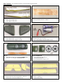
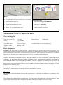
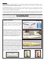
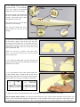
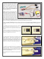
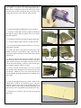
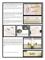
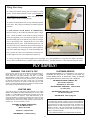
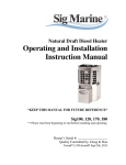
Curtiss Jenny
Kit # SIGRC93ARF
Assembly Instructions
America’s Most Famous World War I Airplane ...
The Curtiss Jenny originated in 1914 in response to the U.S. Army’s desire for a “modern” trainer, an airplane with an enclosed
fuselage with the engine mounted on the front. Prior to the Jenny, the Army had been flying primarily open-to-the-wind pusher
airplanes, and their accident fatality record was gruesome. Even minor mishaps often ended with the pilot and instructor smashed by
a forward-hurtling engine. Eager to get the contract, aviation pioneer Glenn Curtiss answered the Army’s call with two new designs,
the Curtiss Model J and the Curtiss Model N. After testing, the Army asked Curtiss to combine the best features of both designs, thus
the Curtiss “JN” was born. It was inevitable that people flying the new airplane soon expanded the initials “JN” to “Jenny”.
With America's entry into World War I, the Army began ordering large quantities of the Jenny for primary flight training. Some Jennys
were also used in observation, aerial photography, and ambulance duty. Some were equipped with bomb racks for advanced training.
The Navy even had a version of the Jenny on pontoons for seaplane training. By the time production was terminated after the Armistice,
more than 7,000 Jennys had been delivered, making it the most important American airplane design of the war.
After World War I, the Jenny was used in many new, unforeseen, roles. For instance, a Jenny flew the first official airmail flight in the
U.S. in 1918. The first airplane that most Americans of that era saw in person was a Curtiss Jenny, usually being flown by a civilian
“barnstormer”, an gypsy pilot trying make a living traveling from town to town selling rides in his government surplus Jenny. Cheap,
easily replaced Jennys became the mainstay of the colorful “Flying Circus” of the 1920s. The airplane dominated the post WWI years
so completely that this became known as the “Jenny Era” of aviation.
Your Sig Curtiss Jenny is a delightful reproduction of this classic biplane. Being a park flyer, your Jenny is capable of being flown in
small restricted areas. The rugged airframe is very light weight and will provide many enjoyable flights. Take your time and follow
the assembly instructions carefully, and your Curtiss Jenny will to take you on many rewarding barnstorming flights.
SIG CURTISS JENNY SPECIFICATIONS:
Wing Span: 32-3/8” (82.2 cm)
Wing Area: 285.4 sq.in. (18.4 sq.dm.)
Wing Loading: 5.2-5.4 oz. per sq.ft. (16 - 16.3 gr/sq.dm)
Flying Weight: 10.4 - 10.6 oz. (294 - 300gr)
Power System: 180 Class with 4.4:1 Gear Box
Propeller: E.M.I. 8.5” x 8” Propeller (215.9 x 203mm)
Radio Requirements:
(1) 3 or more channel transmitter on “Aircraft” Frequency
(1) Micro Receiver
(1) Micro Servos
(1) 5amp Electronic Speed Control
Battery: 6 cell, 720AAA mAh NiMh Square Pack
Flying Time: 10-15 Minutes
Curtiss JN-4D Jenny on training flight during World War I.
1
Kit Contents:
Do a complete inventory of your kit before starting assembly.
Bag #1: SIGRPFU293
1 . . .Jenny Left Fuselage Side
1 . . .Jenny Right Fuselage Side
Bag #2: SIGRPWB293
1 . . .Jenny Wooden Parts Die-Cut Sheet
Bag #3: SIGRPCW293
1 . . .Jenny Molded Plastic Left Cowl Half
1 . . .Jenny Molded Plastic Right Cowl Half
Bag #4: SIGRPMGDU293
1 . . .Sig180 Class Power System
2 . . .#3 x 10mm Phillips-Head Sheet Metal Screws
Bag #5:
1 . . .Jenny Molded Plastic Cockpit Cover SIGRPCC293
1 . . .E.M.I. 8.5” x 8” Propeller SIGRPPROP293
Bag #6: SIGRPWH293
2 . . .Jenny 50mm Dia. Main Wheels
4 . . .Jenny Wheel Retainers
2 . . .Jenny Molded Plastic Wheel Covers
Bag #7: SIGRPTF293
1 . . .Jenny Foam Horizontal Tail (Stabilizer & Elevator)
1 . . .Jenny Foam Vertical Tail (Rudder & Fin)
Bag #8: SIGRPWK293
1 . . .Jenny Top Wing
1 . . .Jenny Bottom Wing
2
Bag #9:
4 . . .Wing Attach Rubber Bands (#32)
4 . . .#2 x 8mm Phillips-Head Sheet Metal Screws (cowl attach)
2 . . .Velcro® Cockpit attach strips
2 . . .Molded Plastic Control Horn
2 . . .Molded Plastic Control Horn Retainer
2 . . .Molded Plastic Control Horn Clevis
2 . . .Molded Plastic Control Horn Clevis Retainer
2 . . .4mm x 3-11/16” Aluminum Wing Tubes
1 . . .Soft Rubber Prop Shaft Protector
Loose Packed in Box:
1 . . .Wire Main Landing Gear SIGRPBM293
2 . . .Wire Pushrods with “Z” Bend at one end
1 . . .Decal Sheet SIGDKM293
1 . . .Wing Reinforcing Tape (14mm X 43mm)
1 . . .Instruction Manual (not shown)
Additional Items Needed To Complete This Model
Tools and Supplies:
-Small Phillips Screw Driver
-Small Side Cutting Pliers
-Scissors
-Hobby Knife With #11 Blade
-12” Ruler
-1/16” Drill Bit
-Needle Nose Pliers
-Small 90° Square
-Straight Pins
-1” Paint Brush
-Sig 5-Minute Epoxy
-Sig 30-Minute Epoxy
-Sig Thin C/A Glue
-220 Grit Sandpaper
-3/4” wide Scotch® Tape
-Rubbing Alcohol
-#32 Rubber Bands or Low Tack Drafting Tape
Radio Equipment:
Transmitter... We used a HiTEC 4-channel transmitter. Although the Sig Jenny only needs three channels for operation, a four
channel or more transmitter will work fine when used in conjunction with an ultra light receiver and servos, as explained below. We
do not recommend that you buy a new 3-channel transmitter just for the Jenny. If you need to buy a new transmitter, we recommend
that you buy one with four or more channels, that will allow you to fly more advanced models in the future.
Airborne Radio Components... We used the HiTEC FEATHER PACK, which is a package offered by HiTECH of ultra light airborne
components for small electric models like the Jenny. Other radio companies may offer a similar package of light weight airborne
components. The HiTEC FEATHER PACK includes a FEATHER-4 ULTRA LIGHTWEIGHT 4-CHANNEL RECEIVER, Two
HS-55 FEATHER SERVOS and a MICRO SWITCH HARNESS. There are a number of other small receivers and servos on the
market that can be substituted with equally good results. Select components that have specifications similar to the HiTEC equipment
listed. Watch the weight of components carefully as using heavier than recommended equipment will have a detrimental effect on the
flight performance of your Sig Jenny.
Electronic Speed Control... We used a MAXX PRODUCTS MX-9104 MICRO ELECTRIC SPEED CONTROLLER. Other
electronic speed controllers may be used as long as the have a minimum rating of 5 amps.
Batteries:
The transmitter can either have alkaline or rechargeable NiCad batteries. Use the batteries recommended by the manufacturer of the
transmitter.
The airborne battery powers both the electric motor and the airborne radio components. The recommended battery is a 6-cell (AAA)
720 mAh NiMh (Nickel Metal Hydride) rechargeable pack. This pack is matched to the models power system and performance. When
properly charged and with proper throttle management, this battery pack can provide flights in excess of 15 minutes.
3
Chargers:
If your transmitter has rechargeable batteries, use the charger that is supplied or recommended by the manufacturer. This is
usually a slow charger (overnight). Although there will be some variation from transmitter to transmitter, the average fully charged
transmitter battery will provide around two hours of operation.
The airborne battery charger is an extremely important piece of equipment and failure to select an acceptable charger or improper
operation will cause performance problems and unsatisfactory results. A majority of performance related problems can be traced
directly to improperly or incompletely charged batteries.
To charge the recommended battery pack you MUST have a charger that is capable of performing peak detection charging of NiMH
(Nickel Metal Hydride) batteries. We used an Astro Flite 112D charger. This unit is capable of charging at different rates and uses a
12 volt power supply such as a car battery. Other chargers can be used as long as they have capabilities similar to the Astro 112D.
Before Beginning Assembly
Take your time and follow the assembly instructions carefully. The foam parts of your Jenny can be dented easily so be gentle. To
help protect your model during assembly, cover your work bench with a towel or a piece of indoor/outdoor carpet. Use only the glues
specified or you will damage the parts. Specifically, DO NOT use C/A Glue on any of the foam parts or they will be damaged.
Assembly Starts Here:
Slight bevel on inside
1...Use a small piece of 220 grit sandpaper to remove any
burrs from the ends of the two 4mm x 3-11/16” Aluminum
Wing Tubes. Now use your hobby knife to slightly
bevel/sharpen the inside of one end of one tube as shown.
Remove burrs from ends
Twist tube to bevel
2...Prepare the fuselage sides for assembly by taking the
sharpened end of the aluminum tube to open up the four holes
in the fuselage sides. Lay the fuselage side flat on a firm
surface and gently press the tube into the hole with a twisting
motion to finish cutting through the fuselage sides. Next, use
your Hobby Knife to open up the pushrod holes in the rear of
each fuselage side. Finally, lightly sand the mating surfaces
of both sides to remove any flashing from the foam.
3...Carefully apply 30 minute epoxy to one of the fuselage
sides as shown. Since the epoxy is many times stronger than
the foam, you only need to use a small amount to bond the
fuselage sides together. By applying the epoxy in this manner
you will eliminate having a lot of epoxy squeezing out on the
outside of the model. We recommend using #32 rubber bands
to hold the fuselage sides together until the epoxy hardens.
Use care to make sure that the fuselage is straight and not bent
or twisted. NOTE: You can also use low-tack drafting tape to
hold the fuselage sides together if preferred. However, use
caution because tape can pull the paint off the model if the
adhesive is too tacky. Use tape only on areas of the model that
will not be seen after it is completely assembled.
GOOD
BAD
Apply epoxy sparingly to inside
edge of one fuselage side
as shown.
Fuselage side (cross section)
Fuselage Straight
4
Fuselage Bent
4...Use 5-minute epoxy to glue the
plywood Firewall, (4) Cowl Mounts,
Servo Tray, Tailskid, and aluminum
Wing Tubes in place in the fuselage.
Firewall &
Cowl Mounts
Servo Tray
Be sure the firewall is seated snugly into
the recess molded in the front of the
fuselage. This provides built-in down
and right thrust to the motor.
Glue the servo tray in with the grain
running across the fuselage.
The wing tubes should stick out an
equal amount on each side of the
fuselage.
Tail Skid
Wing Tubes
5...Use 3/4” wide 3M Scotch® Crystal Clear Tape to hinge
the tail surfaces. Apply a strip of tape to the top of the
Horizontal Tail and another strip on the bottom. Each tape
strip should be centered over the slot between the parts and
should run the full length of the slot. Do the same to both
sides of the Vertical Tail.
NOTE: 3/4” wide tape is available at most office supply
stores. Use only clear tranparent tape. Do not use frosted
Scotch® Magic Tape.
6...Use a sharp new hobby knife to trim the foam tabs and
excess tape from both ends of the horizontal tail and the top
and bottom of the rudder.
7...Use a small diameter dowel with a smooth rounded end,
or similar shaped object, to indent the tape on each side of
the tail surface until the two pieces of tape contact each other
in the middle of the hinge gap, creating the finished hinge.
8...Apply the fin decal to the unpainted side of the fin and apply the rudder decals to both sides of the rudder.
DECAL APPLICATION NOTES: The decals provided in this kit are a type of water transfer decal that you may not have used
before. They are extremely thin and light, and when they are on the model they look like they’re painted on. Notice that the decals
are printed on the paper carrier upside down. There is a thin clear plastic sheet over the decals that protects a low tack adhesive.
5
To apply the decals, leave the clear plastic in
position while you cut the individual
marking from the main sheet. Then remove
the clear plastic and place the decal on the
model in the desired position, adhesive side
down. Make sure you get the decal exactly
where you want it. The light tack adhesive
allows the decal to be picked up and
repositioned if necessary. With the decal in
the proper position, use a brush to generously
apply cold tap water to the paper. The paper will immediately begin to soak up the water. Let the paper soak for at least 30 seconds,
and then carefully SLIDE the paper from the top of the decal. DO NOT try to lift the paper from the decal as it will damage the decal.
Also, after the paper is removed DO NOT try to move the decal on the model surface. The decal is very thin and fragile. If the decal
has air bubbles under it, use a soft cloth to pat out the bubbles, making sure that you pat straight up and down, not sideways. DO NOT
try to push the bubbles sideways out from under the decal. While these decals are more fragile than “normal” decals, the end result
is a marking that looks like it was painted on. Allow the decal to dry at least one hour before handling.
9...Use your hobby knife to open the control
horn slots in the rudder & elevators. Insert
the rudder control horn so that the arm sticks
out of the left side of the rudder. Insert the
elevator horn from the top so that the horn
sticks down from the bottom. Now slide the
retainer plates onto the horns and press into
position to lock the control horn in place.
You will hear or feel two clicks when the
retainer is in the proper position.
GOOD
10... Attach the lower wing to the fuselage with two rubber
bands. Use 5 minute epoxy to glue the horizontal
stabilizer to the fuselage. The stabilizer should be roughly
parallel to the wing and should not tilt to the left or right.
The slot for the fin mounting tab in the stabilizer should be
aligned with the corresponding slot in the fuselage. Use
several straight pins to hold the stabilizer in position until
the epoxy sets. Any excess epoxy that enters the fin slot in
the stabilizer and fuselage must be cleaned out before it
dries.
BAD
11...Use 5 minute epoxy to glue the vertical stabilizer to the
fuselage. The vertical stabilizer should be 90° to the
horizontal and should not tilt to the left or right. Use
several straight pins to hold the vertical stabilizer in
position until the epoxy sets.
BAD
GOOD
90°
12...Plug the airborne electronics together and test for proper function. The two servos are plugged into channels 1 and 2 on the
receiver. The electronic speed control plugs into channel 3 on the receiver. Plug the motor, without the prop in place, into the
output of the electronic speed control. Fully charge the transmitter and airborne battery.
6
To operate the system, first turn the transmitter
on and place the throttle stick in the low
position. Now plug the airborne battery into
the input side of the electronic speed control
and the system is operational (see NOTICE:
below). Test the system by moving the right
stick on the transmitter, which should move the
rudder and elevator servos.
Initially, the motor is not armed and will not
function when you move the throttle stick. To
arm the motor you must move the throttle stick
to the high position and hold it there for
several seconds. Then move the throttle stick to
the low position and hold it there for several
seconds. The motor is now armed. Moving the
throttle stick now will activate the motor. Make
sure everything is functioning properly on your workbench BEFORE you install any of the components into the model. While the
radio is on make sure that the rudder & elevator trim levers on the transmitter are in the centered position. This will make sure that
the servos are centered. Unplug the battery from the electronic speed control to turn the system off.
NOTICE: The HiTEC FEATHER PACK airborne package we used came with a small MICRO SWITCH HARNESS. We elected not
to use the swith harness to save weight. It is easy to turn the radio system on and off simply by plugging in and unplugging the battery pack.
13...Install the servos into the plywood servo tray. The servo
output arms should be at the forward end of the servo. Use
care to not move the servo output arms from their neutral
position.
Feed the wire pushrods into the fuselage from the rear exits.
The “Z” bends should be at the front and attached to the
output arms. Tighten the servo arm screws.
14...Slide the plastic Control Horn Clevis Retainer onto the
rudder pushrod wire. Snap the plastic Control Horn Clevis
into the rudder control horn. Then with the rudder servo in
neutral position, hold the rudder in neutral while you lay the
threaded end of the pushrod wire into the groove in the
plastic clevis. Push the wire down firmly into the groove.
Clevis
Retainer
15...Slide the Clevis Retainer onto the Clevis, trapping the
pushrod wire in place. Check to be sure that the rudder is still
in the neutral position. If it is not, unsnap the clevis from the
control horn and adjust the pushrod length by screwing the
clevis in or out on the threads.
Now repeat this process to install the clevis onto the elevator
pushrod.
7
Clevis
16...Finally, plug the servos and electronic speed control
into the receiver. Place the receiver in the fuselage beneath
the servos. The electronic speed controller sits on the
bottom of the fuselage in the battery compartment, between
the servos and the firewall. Plug the battery into the system
and check the radio for proper operation. If the servos move
in the wrong direction, use the servo reversing switches on
your transmitter to change the direction of travel.
Adjust the control throws to the following measurements:
Rudder: 3/4” Right 3/4” Left
Elevator: 1/2” Up 1/2” Down
17...Drill a 1/16” hole in the bottom of the fuselage at the
location shown. Feed the receiver antenna through this hole.
Pull the antenna back to the rear of the fuselage and hold it
in place just in front of the tail skid with a piece of Scotch®
Tape. Allow the full length of the antenna to trail behind the
model. Do not cut the antenna to shorten it, as that will
reduce the reception range of your radio.
18...Remove the cabane struts from the die cut plywood
sheet and glue them to the fuselage sides using 5 minute
epoxy. They should sit on the ledges on the bottom of the
pockets on the side of the fuselage. When viewed from the
front the cabane struts should be vertical and should not lean
to one side or the other.
19...Trim the plastic Cockpit Cover as shown. Test fit the
Cockpit Cover to the fuselage and adjust as required to
achieve a proper fit. Note: A sharp hobby knife and a
miniature snips are the best tools for trimming the part.
Remove the paper from the adhesive on one side of the
velcro squares and apply the two velcro squares to the top of
the fuselage as shown. Now remove the paper from the
adhesive on the top of the velcro and press the plastic
cockpit cover into position to attach the velcro to the cover.
Velcro
Velcro
8
22..Apply the Wing Reinforcing Tape (14mm X 43mm) to the leadmountwing.
holes The
in the
firewall
a
ing20...Pre-drill
edge of boththe
thetwo
topmotor
and bottom
tape
shouldwith
be cen1/16”
drill
bit.
Use
the
two
#3
x
10mm
Phillips-Head
Sheet
tered on the leading edge left and right and should be applied so
Metal
Screws
to attach
the motor
to thehalf
front
of the
that
it wraps
around
the leading
edge with
on the
top model.
of the
Feed
the
motor
connector
through
the
hole
in
the
front
of the
wing and half on the bottom of the wing.
fuselage and connect it to the electronic speed controller.
Apply the two star decals to the top of the top wing and allow to
dry.
Remove the two plywood wing struts from the die cut sheet. Insert
the struts through the bottom wing. Use 5 minute epoxy to attach
the struts to the bottom wing. The struts should be aligned vertical.
Now glue the top stubs into the top wing with 5 minute epoxy.
Align the wings square and allow the epoxy to dry.
21...Trim and assemble the molded plastic Cowl as follows:
Step 21A
Step 21B
Step 21C
Step 21D
A. Tape the left and right cowl halves together and mark the
back edge for cutting. Study the picture closely to see where
the marks should be.
B. Untape the cowl halves and trim the plastic off the back.
C. Trim
the “bubble”
of each
cowllanding
half.
22..Use
5 minute
epoxy to off
gluethe
thefront
two face
die cut
plywood
gear inserts into position on the landing gear. The short one goes
Cutof
thethe
bottom
flange
close
at theD.
front
landing
gear off
andboth
the cowl
taller halves.
one is atCut
theasrear.
to the flange as possible.
E. Notice that the left cowl half has recessed joiner strips
molded in along the top and bottom edges. Trim away the
excess plastic at the front and rear of each joiner strip as shown
in this picture.
the rightPlastic
and left
cowlCovers
halvesastogether.
The aright
Remove bubble
Trim F.
thePlace
two Molded
Wheel
shown. Use
1/16”
half
should
fit
over
the
recessed
flanges
on
the
top
and
bottom
drill bit to drill a hole for the axle in the center of each cover.
of the left half. Hold the cowl together with tape and test fit
ontoone
theWheel
front of
the fuselage.
the fit
good,allcarefully
gluein. Step 21E
Joiner Strip
Press
Retainer
on eachIfaxle
andisslide
of the way
the
cowl
halves
together
with
thin
C/A
glue.
Now place the wheel, wheel cover and outer Wheel Retainer into
position. The outer wheel retainer should spaced so that the wheel
Fit the cowl back onto the model. Use a 1/32” bit to drill
turns G.
freely.
four mounting holes through the cowl and into the plywood
cowl mounts. Mount the cowl to the model using the four
#2 x 8mm Phillips-Head Sheet Metal Screws to attach the cowl
to the model.
23..Attach
the wing on the model using 4 rubber bands. Now
Joiner Strip
Remove flanges
Steps 21F & G
install the landing gear by pressing the front and rear upper ends
completely into the slots in the fuselage. Attach the number decals to the fuselage sides between the wing and the tail surfaces.
22...Apply the Wing Reinforcing Tape (14mm x 43mm) to the
24...Plug the speed control into the receiver. Charge and connect
leading edges of both the top and bottom wings. The tape
theshould
airborne
andleft-to-right
test the radio
system
be battery
centered
onand
thepower
leading
edge,WITHand it
THEbePROPELLER
OUT
should
applied so thatATTACHED.
it wraps around the leading edge with
half sure
on the
topallofofthe
and half
on the
bottom
of the properly.
wing.
Make
that
thewing
controls
and the
throttle
function
23...Apply
the two
starout,
decals
to theattach
top ofthethe
top wing
andthe
When
everything
checks
securely
propeller
onto
allow to dry.
power system.
25...Place the battery in the model and install the Plastic Cockpit
Cover. Check the balance of the model. To do this, turn the model
upside down and support the model on your finger tips placed 1/2”
back from the leading edge of the bottom wing. Hold your fingers
9
24...Remove the two plywood wing struts from the die-cut
sheet. Insert the struts through the bottom wing. Use 5-minute
epoxy to attach the struts to the bottom wing. Make sure the
struts are aligned vertically before the glue sets.
Now glue the top stubs of the wing struts into the top wing with
5-minute epoxy. Align the wings square and allow the epoxy to
dry.
25...Use 5-minute epoxy to glue the two die-cut plywood
landing gear inserts into position on the Wire Main Landing
Gear. The short plywood insert goes at the front of the landing
gear, and the taller one goes at the rear.
Trim the flange off of the two Molded Plastic Wheel Covers as
shown. Use a 1/16” bit to drill a hole for the axle in the center
of each wheel cover.
Press one Wheel Retainer onto each axle, and slide it all of the
way in as far as possible. Now slide on the wheel, plastic wheel
cover. Then install the outer Wheel Retainer. Make sure the
wheels turn freely.
Remove
flange
Optional: You will see in some pictures that we painted our
wheel covers to match the fuselage color. All of the plastic
parts and the foam parts can be painted with water-based
acrylic “craft” paint. Do not use other paints on the foam.
26...Attach the wings on the model using 4 rubber bands (2 for
the top wing and 2 for the bottom wing). We recommend
putting the bottom wing rubber bands on first, being carefull to
line up the slots in the bottom wing with the slots in the bottom
of the fuselage. Then install the landing gear by pressing the
front and rear upper ends completely into the slots in the
bottom of the fuselage. Finally, install the top wing rubber
bands.
27...Apply the number decals to the fuselage sides.
10
Flying Your Jenny
28...Charge the airborne battery pack and connect it to the
system. Test the radio and electric motor system WITHOUT
THE PROPELLER ATTACHED. Make sure that all of the
controls and the throttle function properly.
Rubber
Prop Shaft
Protector
29...When everything checks out, securely attach the propeller
to the motor. Don’t forget to install the soft rubber prop shaft
protector!
30...BALANCING YOUR JENNY IS IMPORTANT!
Place the battery in the model and install the plastic cockpit
cover. Check the balance of the model by turning it upside
down and supporting it on your finger tips placed 1/2” back
from the leading edge of the bottom wing. Hold your fingers
close to the fuselage sides. Supported this way your model
should hang perfectly level. If the model hangs tail low, you
must move the receiver and battery forward in the fuselage, or
if they are already as far forward as possible, add weight to the
nose of the model until it hangs level. If the model hangs nose
low, you must move the receiver and battery towards the rear,
or add weight to the tail of the model until it hangs level.
Balance 1/2” back from leading edge of bottom wing.
Do not attempt to fly your Jenny until it is properly balanced!
31...Always pre-flight your model thoroughly before each flight. It is your responsibility to verify that your model is airworthy.
Always follow established safety guidelines while installing the battery, operating the motor, radio, and while flying the model.
FLY SAFELY!
WARNING! THIS IS NOT A TOY!
CUSTOMER SERVICE
Flying machines of any form are not toys! Because of the speeds that airplanes must achieve in order to fly, they are capable of causing
serious bodily harm and property damage if they crash. IT IS YOUR
RESPONSIBILITY AND YOURS ALONE to assemble this model
airplane correctly according to the plans and instructions, to ground test
the finished model before each flight to make sure it is completely
airworthy, and to always fly your model in a safe location and in a safe
manner. The first test flights should only be made by an experienced R/C
flyer, familiar with high performance R/C aircraft.
SIG MANUFACTURING CO. is committed to your success in
assembling and flying this kit. Should you encounter any
problem building this kit, or discover any missing or damaged
parts, please feel free to contact us by mail or telephone.
SIG MANUFACTURING COMPANY, INC.
401-7 South Front Street
Montezuma, IA 50171-0520
SIG MODELER’S ORDERLINE: 1-800-247-5008
(to order parts)
JOIN THE AMA
SIG MODELER’S HOTLINE: 1-641-623-0215
(for technical support)
The governing body for radio-control model airplanes in the United
States is the ACADEMY OF MODEL AERONAUTICS, commonly called
the AMA. The AMA SAFETY CODE provides guidelines for the safe
operation of R/C model airplanes. While AMA membership is not
necessarily mandatory, it is required by most R/C flying clubs in the U.S.
and provides you with important liability insurance in case your R/C
model should ever cause serious property damage or personal injury to
someone else. For more information, contact:
SIG WEB SITE: www.sigmfg.com
LIMIT OF LIABILITY
The craftsmanship, attention to detail and actions of the builder/flyer
of this model airplane kit will ultimately determine the airworthiness,
flight performance and safety of the finished model. SIG MFG. CO.’s
obligation shall be to replace those parts of the kit proven to be
defective or missing. The user shall determine the suitability of the
product for his or her intended use and shall assume all risk and
liability in connection therewith.
ACADEMY OF MODEL AERONAUTICS
5161 East Memorial Drive
Muncie, IN 47302
Telephone: (765) 287-1256
KIT CONTENTS SUBJECT TO CHANGE WITHOUT NOTICE.
AMA WEB SITE: modelaircraft.org
11