1
97585-UAI-A-1004
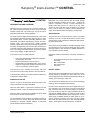
Simplicity ® Intelli-Comfort ™ CONTROL
THE Simplicity ® Intelli-Comfort ™ CONTROL
INTRODUCTION AND OVERVIEW
Welcome to the new Intelli-Comfort ™ Control, a digital control system designed specifically for the 3 thru 25 ton single
package rooftop units. The control logic of Intelli-Comfort ™
extends beyond current control capabilities.
The Intelli-Comfort ™ digital control performs all of the control
and monitoring functions that were originally done by separate discrete relays, controls, interlocking hardware, and a
Thermostat. This reduces manufacturing, service, and maintenance costs. The Intelli-Comfort ™ digital controller
includes sophisticated control of the individual components of
the HVAC cooling/heating unit, and has built-in rules that protect those components and optimize the control to its environment. The cooling and heating modes are protected against
short cycling, slugging, multiple restarts, etc.
In the Intelli-Comfort ™ control, there are:
•
•
•
•
a list of user-selected option settings and setpoints
recorded within the control;
inputs monitored by the Intelli-Comfort ™;
specific fixed rules and timings built in to the control
outputs to compressors and heat via the Simplicity ®
control, economizers, and other options.
Intelli-Comfort ™ has a real-time clock function, with minimum of ten hours ‘Time-of-day retention’ with unit power off.
If connected to a network, the control requests an address by
a press of the Address button.
Diagnostics may require patience due to internal timings.
Normal observable conditions are the same - contactor 1M
pulled in, compressor 1 running - but the control does not
identify what it has just done or is about to do. The IntelliComfort ™ control will take action according to its internal
rules. A call for cooling, for example, will be compared with
supply air temperature before energizing a cooling stage.
ERROR HISTORY
The Intelli-Comfort ™ control stores up to 5 of the most recent
alarms in a First In, First Out (FIFO) manner. As the control
collects alarms, it will overwrite the oldest alarm after the history buffer becomes full.
Some system errors will initiate a controlling response as well
as being stored in the error memory buffer. See the “Troubleshooting” chapter in this manual for a detailed description of
how controller errors are handled.
Data items stored for maintenance / run history, in addition to
Alarms:
•
•
•
•
Accumulated run times for each compressor and
heat stage
Unit model number
Unit serial number
Unit Name
DIGITAL LINGO
This training manual is intended to help you with the commissioning process by illustrating the use of tools such as the
control’s digital input and software engineered specifically for
starting up and servicing a rooftop unit.
DIAGNOSTICS VIA LED
There is an LED on the board that shows the status of the
control and alarms (see Status LED Table).
When the Alarm button is pressed and released one time
within five seconds, it will re-enunciate the last five Alarms.
When this button is pressed and released two times within
five seconds, it will clear all stored alarms.
The error details for most conditions are stored in summary in
the Intelli-Comfort ™ Control, along with all data and can be
accessed by a personal computer interface, or Palm Pilot
(Some interfaces still in development).
Unitary Products Group
You should become familiar with some common terminology
and lingo used in the digital controls industry.
If this is your first exposure to the world of digital controls you
may experience a lot of new terms, acronyms and technical
lingo commonly used in the controls industry. For example,
the Intelli-Comfort ™ input and output hardware points are
described as analog, relating to a continuous scale of value
readings such as a temperature sensor ranging from -40°F to
160°F range, or binary, meaning 2- states, either on or off,
open or closed, true or false, one or zero. The term “digital”
also means two states and its use is often interchanged with
“binary”. These points may be either factory- or field-set.
97585-UAI-A-1004
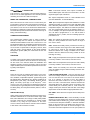
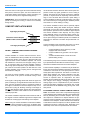
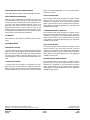
ANALOG TO DIGITAL CONVERTER
Computers can only understand a simple binary language.
Remember, “binary” means two states - ON or OFF. Analog
(continuous) values of voltages, currents, and resistances are
supplied by sensors and transducers to the control. These
values must be converted in to a binary code so that the computer can understand them. This conversion process is performed through a combination of hardware and software. For
example, the 0-5VDC analog value from a static pressure
transducer is divided into thousands of steps with a binary
coded number, often called “counts”, assigned to each step...
control, only basic operation instructions are stored in this
type of memory.
EEPROM (Double “E” Prom) - is also non-volatile, but this
type of memory requires a special process to be written. This
memory can be written to and changed by the microprocessor. This is the type of memory that the control program is
stored in the Intelli-Comfort ™ control.
FIRMWARE - “Firmware” is software, program instructions,
or applications, and stored in EPROM or EEPROM memory.
RAM - Random Access Memory is a volatile memory. It will
be erased when a power fail occurs. This memory is used as
a kind of “scratch pad” for the controller. Temporary instructions and information such as an output controlling action like
driving the economizer dampers open is stored here. When a
power loss occurs or if the controller is sent a manual reset
using a control pushbutton, this memory is cleared and initialized.
FAULT TOLERANCE - Fault Tolerance of the Intelli-
Comfort ™ control involves two issues: Hardware fault tolerance deals specifically with the electrical characteristics of
the controller - how much overvoltage or power surge the
controller can withstand before damage occurs, and whether
internal comparisons are verifying that the control is calculating and communicating properly. Software fault tolerance in
this technology consists of comparing results to previous values and to reasonable values.
0
1
2
3
4
5
6
7------------- n
BINARY NUMBER EQUIVALENT
FIGURE 1 - ANALOG TO DIGITAL CONVERTER
SOFTWARE TERMINOLOGY
A digital controller handles its control functions through software programming rather than with interlocking hardware and
wiring. The software then becomes key to how controlled
functions are handled. Software is a set of statements
(referred to as the “program” ) that define the function of the
controller’s internal microprocessor computer.
Software procedurally tells the computer the sequence and
order of tasks that need to be performed using a language
that the computer can understand.
Software is stored in several types of computer memory.
Each type has a specific function to perform.
EPROM - This is “non-volatile” memory, meaning it will not be
erased on a power loss. This memory is usually programmed
prior to assembly of the controller. Since this memory is not
changed during normal operation of the Intelli-Comfort ™
Unitary Products Group
COMMUNICATIONS BUS
Networked communications may also be new to you. It
relates to connecting several Simplicity ® rooftop units to a
network that can be monitored and controlled remotely from
network computer workstations. You will find this typically on
large installations where central control, monitoring, and
energy management issues become a critical factor in operating a large complex such as a manufacturing facility.
The Intelli-Comfort ™ Control has the ability to be networked
into a larger system using the MODBUS communication protocol. A communication protocol is simply a set of rules that
determine how two systems communicate with each other
over some medium such as a pair of wires, phone line, radio
waves, etc. The transmission medium may also be called a
gateway, pathway, or bus. An “open” protocol such as MODBUS is a publicly published set of rules that any equipment
manufacturer can use to network into another manufacturer’s
equipment.
COMPONENT DESCRIPTION
This section describes the main components of Simplicity ®
Intelli-Comfort ™ control. These components consist primarily of controllers, hardware to handle signal inputs and control outputs.
2
97585-UAI-A-1004
THE Intelli-Comfort ™ CONTROLLER
Intelli-Comfort ™ is a proprietary, microprocessor-based controller for use in HVAC applications. The controller provides
monitoring and control for a total of 22 outputs.
WIRING AND TERMINATION, COMMUNICATIONS
Most connections to the Intelli-Comfort ™ Control are by wiring harnesses. There are also screw terminal connections for
thermostat inputs and for communications via an RS-485
port. However, Intelli-Comfort ™ should not be installed with a
thermostat. It is designed to replace the thermostat’s function.
The thermostat input screw terminals should be used only for
testing and troubleshooting.
COMMUNICATION ADDRESS
The communication address button is used to identify a
Simplicity ® rooftop unit to a network, and “capture” the next
available network address for that unit. Intelli-Comfort ™ can
be networked together for centralized monitoring and control.
Much like we need a unique street address in our homes so
we can receive our postal mail or emergency services, these
units also need a unique address so the central Facilities
Management System (FMS) can communicate to each unit
individually.
BAS - Economizer override; if this option is enabled, an
external BAS system will control the economizer 2-10 VDC
signal through this pair of terminals.
ST - Space Temperature sensor is a field installed sensor
(PN: 025-38928-000 - w/ Override Button).
SSO - Space Temperature Adjust is field installed. It is a slide
adjustment located on a space sensor (PN: 025-38927-000)
with a slide bar potentiometer. It is used to offset the space
temperature setpoint. This slide-bar is a 20K ohm potentiometer. The programmable range for the Setpoint adjust is +/5°F. For example, if the Space Temperature setpoint is set to
74°F, the SSA is programmed to +/- 3°F and the SSA is
adjusted fully to the + position, the new controlling space setpoint will be 77°F.
OAT - The outside air temperature sensor (PN: 031-01916000A) is a factory-installed 10 K NTC sensor. Its range is
from -50°F to 250°F.
OAH - Outside Air Humidity sensor, provides a 0-10 VDC signal to the controller over a range of 0 to 100% relative humidity. This input is used for the economizer calculation to
determine whether free cooling is available and to switch
between minimum outside air and using outside air as the
first stage of cooling.
ACRONYMS
A number of acronyms are used throughout this training manual. These are specific to the Intelli-Comfort ™ control. They
are also used in the Technical Guide and Installation and
Operation manuals. Acronyms are used to refer to input and
output hardware points and software parameters such as timing delays and setpoints.
SAT - Supply Air Temperature sensor (PN: 031-01915-000A)
is a factory-installed - 50°F to 250°F, 10 K NTC sensor.
RAT - Return Air Temperature sensor (PN: 031-01917-000A)
is a factory-installed - 50°F to 250°F, 10 K NTC sensor.
INPUTS
RAH - Return Air Humidity The control will calculate the
return air enthalpy using the relative humidity and return temperature inputs.
There are two types of hardwired input points on the IntelliComfort ™ control: Analog and Binary. These may be sensors, feedback, or adjustable setpoints. Typical analog inputs
[AI] include Space Temperature (ST), Supply and Return Air
Temperatures (SAT, RAT), and Building Pressure Sensor
(BPS). The binary inputs (BI) on the Simplicity ® IntelliComfort ™ use a dry contact input to determine the status of
a monitored point. Typical BI points are Fan Status (APS), Filter Status (DFS), and Compressor Status (HPS1-2, LPS1-2,
C1O-2O).
LOW VOLTAGE DETECTION - This input monitors the 24
VAC for low voltage conditions. The input has two thresholds,
one at 16 VAC and one at 19.2 VAC. If the control needs to
turn on a contactor, it will look to see if the voltage is
above19.2 VAC before it will turn it on. If the voltage is not
above 19.2 VAC, it will hold off the contactor and flash the
appropriate flash code. This flash code is not an alarm. If the
control already has contactors pulled in, it will monitor the
voltage and drop the contactors and shut down if the voltage
drops below 16 VAC and flash the appropriate flash code.
ANALOG INPUTS (AI)
SPC TEMP - offset value from the space sensor offset potentiometer.
Analog inputs require parameters that define the input’s characteristics. Attributes of an AI include the linear range, alarm
limits, alarm differential, and change of state (COS) enable.
The input values may be overridden by a external system
command or by using the input buttons on the IntelliComfort ™ board. This is useful to override current conditions
to test certain control functions or modes.
3
DEMAND VENTILATION / IAQ - Indoor Air Quality. The IAQ
expects a 0-10 VDC signal to the control from a field supplied
and installed Carbon Dioxide (CO2) sensor. Indoor air quality
is monitored for adequate ventilation. In Demand Ventilation
Mode, as the CO2 levels in the building rise above the programmed setpoint, more fresh air must be brought in. The
economizer is therefore adjusted to a more open position as
Unitary Products Group
97585-UAI-A-1004
necessary. The linear ranging for IAQ sensor input is from 0
to 10,000 ppm. The Demand Ventilation setpoint is adjustable
from 0 to 2000 ppm and is set at the factory at 1000 ppm.
INTERACTING THROUGH THE Simplicity ®
Intelli-Comfort ™
DIFFERENTIAL DEMAND VENTILATION / IAQ - Outside
IAQ sensor The control can operate with the Outside IAQ
sensor and the inside IAQ sensor to provide Differential
Demand Ventilation. This means it will operate to a setpoint
based on the difference between outside and inside CO2 levels.
INITIAL STARTUP OPTIONS
BINARY INPUTS (BI)
APS - Supply Fan status is monitored by an Air Proving Status switch (which is a field installed option). The APS monitors the difference in pressure between the suction and
discharge of the fan.
PURGE - This signal represents Building Purge (P) calls from
an external source. If an external source is wired to the system, this input is connected to the board via screw terminals.
This signal is loaded with a resistor to maintain voltage levels
and to prevent “floating” of signals.
FILT - Dirty Filter switch (customer supplied, field installed)
on factory-provided harness connections input to provide a
filter status to the control. The control will alarm only after 24V
has been sensed for ten minutes.
OUTPUTS
ANALOG OUTPUTS (AO) - Analog outputs provide a 2-10
VDC signal to operate controlled devices. The IntelliComfort ™ is currently configured to use only 2-10 VDC output to the Economizer Damper. Since this output is analog, it
is continuous between 2 and 10 Volts and is proportional to
the 0 to 100% drive position of the device.
ECO - Economizer Actuator - The modulating Economizer
uses a Belimo spring-return actuator. This actuator uses a 210 VDC signal to drive the dampers open. The actuator
drives 95 degree rotation.
W1 and W2 - Heating calls - These are 24vac switched by
two onboard relays that drive the heat through the
Simplicity ® board.
Commissioning a new Simplicity ® installation requires some
field adjustments to the Intelli-Comfort ™ control program.
Most of these adjustments simply involve setting up the various setpoints that are specific to your customer’s needs (i.e.
economizer minimum position) or enabling some extended
options that are integrated into the Intelli-Comfort ™ control.
METRIC OPERATION (ENGLISH)
The factory default for this option is OFF. The metric (SI) conversions are part of the PC software; when the Metric parameter is selected, temperature setpoints and readings will
convert to Centigrade (°C).
SETTABLE SYSTEM PARAMETERS
The following headings list each parameter’s name and its
default setting. The control is set at the factory for the options
of the specific unit; if a replacement control is being installed,
the entire parameter set must be matched to the unit. The
value in (parentheses) is the value of a parameter in an unconfigured control.
COMPRESSORS - (2) - This tells the control the number of
compressors available. The Factory Default [the value in an
unconfigured replacement control] is 2 and can be adjusted
from 1 to 2.
SAT CONTROL FOR COOLING - (ON) - This tells the control if it is going to do excessive SAT monitoring and tripping
or not, for Cooling. The SAT should be maintained in an
acceptable range in order to achieve reliable compressor
operation. The compressor trip limits are user adjustable
between 40°F and 65°F in one degree increments. The
default cooling trip limits are 50°F for stages 1 - 2. When the
SAT drops below the trip limit for each respective compressor, that compressor is locked out and a 5 minute ASCD is
initiated for that compressor. If this option is enabled, remember to set the compressor cooling limits for low limit trip.
ECONOMIZER - (ON) - Identifies there is an Economizer
Installed.
Intelli-Comfort ™ PROGRAMMING OPTIONS
The paragraphs below provide a definition of, and specify the
function related to, each of the parameters that are fieldadjustable using the interfaces available. The Simplicity ®
Unit is shipped from the factory with the necessary options
pre-programmed as indicated by the model nomenclature. It
is always a good practice, though, to verify that the correct
parameters are properly configured for the unit you are commissioning. You can find a complete list of field-adjustable
parameters in the “Settable System Parameters” section.
Unitary Products Group
ECONOMIZER MIN POSITION - (20%) - Identifies the minimum outdoor damper position that will be used for the Occupied mode. Adjustable from 0-100%, the Economizer
Minimum Position default is 20%.
ECONOMIZER FIRST STAGE SETPOINT - (55°F) - Identifies what Supply Air Temperature to maintain for a call for first
stage of cooling. This is used in cooling mode with Economizer operation. The setpoint is set at 55°F with an adjustable range from 40°F to 65°F.
4
97585-UAI-A-1004
ECONOMIZER SECOND STAGE SETPOINT - (50°F) - Identifies what Supply Air Temperature to maintain for a call for
second stage of cooling. This is used in cooling mode with
Economizer operation. This setpoint is set at 50°F with a
range from 40°F to 65°F.
OUTSIDE AIR HUMIDITY (OAH) SENSOR ENABLE - (OFF)
- Identifies the control is expected to use Outside Air Enthalpy
(calculated from Outside Air Temperature and Outside Air
Relative Humidity sensed values) to determine if Outside Air
can be used for cooling.
The control is self-configuring to the best available decision
strategy for free cooling availability. For example, if it detects
that OAT and OAH and RAT and RAH sensors are all connected and reliable, it can be configured for Differential
Enthalpy operation. If one of the return air sensors should fail,
the control will reconfigure for Outside Enthalpy operation,
etc.
If the OAH Sensor Enable option is turned ON, it means that
the Outside Enthalpy Operation, or better decision strategy, is
expected (and supported by installed sensors). If the appropriate sensors are not installed, or one of them failed, a sensor failure alarm is set. The alarm can be turned off by turning
off the OAH Sensor Enable option. Thus, the option setting is
used to reflect the desired operation and mainly to control
sensor failure alarms.
The option setting can be viewed as specifying that the selfconfigured economizer decision strategy has to be at least
this, or better, otherwise an alarm is set. If the option is OFF,
the control still may self configure to Outside Enthalpy Operation, or even to Differential Enthalpy Operation (if all needed
sensors are available), but this option setting will also allow
the decision strategy based on only OAT (in case other sensors fail, or are not installed) without setting an alarm.
OUTSIDE AIR ENTHALPY SETPOINT - (27 BTU/LB) - Identifies the outside air enthalpy limit. Below this limit, outside air
is available for cooling. See enthalpy chart. This parameter
uses a one BTU/LB hysteresis on each side of the limit. The
setpoint is preset to 27 BTU/ LB with an adjustable range
from 10 to 50 BTU/LB.
RETURN AIR HUMIDITY (RAH) SENSOR ENABLE - (OFF)
- Identifies that the control will compare Outside Air Enthalpy
(calculated from Outside Air Temperature and Outside Air
Relative Humidity sensed values) and Return Air Enthalpy
(calculated from Return Air Temperature and Return Air Relative Humidity sensed values). The control will use the air
stream with the lower enthalpy for cooling.
The control is self-configuring to the best available decision
strategy for free cooling availability. For example, if it detects
that OAT and OAH and RAT and RAH sensors are all connected and reliable, it can be configured for Differential
Enthalpy operation. If one of the return air sensors should fail,
5
the control will stop using rules that involve RAH and set an
alarm.
If the RAH Sensor Enable option is turned ON (and supported by installed sensors), Differential Enthalpy Operation
can be enabled. If the appropriate sensors are not installed,
or one of them failed, a sensor failure alarm is set. The RAH
alarm can be turned off by turning off the RAH Sensor Enable
option. Thus, the option setting is used to reflect the desired
operation and mainly to control sensor failure alarms.
ECONOMIZER LOADING TO CONTROL SAT - (ON) - Identifies if the control is going to use Economizer Loading to control excessive SAT [supplying warmer outside air to keep SAT
from going too low]. This parameter is only applicable outside
the normal Economizer operation. During the Economizer
operation, the loading function is always performed and is an
integral part of the control algorithm.
OCCUPIED - (from settings in Weekly Schedule and Holiday Schedule Tables.) See discussion in Sequence of Operation.
UNOCCUPIED - (from settings in Weekly Schedule and
Holiday Schedule Tables.) See discussion in Sequence of
Operation.
COMFORT VENTILATION MODE - (OFF) - Comfort Ventilation is a SAT control mode that controls SAT during “satisfied”
periods in a fairly wide temperature band, using mostly Outside Air, and also cooling and heating stages as necessary.
To enable Comfort Ventilation, the programmable parameter
“Comfort Ventilation Mode” must be set to ON (default setting
is OFF).
For a detailed explanation of Comfort Ventilation, refer to the
Sequence of Operation in this manual.
COMFORT VENTILATION HIGH SUPPLY AIR SETPOINT (80°F) - Identifies the High Limit Setpoint for the Comfort Ventilation mode. For a stable operation of Comfort Ventilation
function, the High Supply Air Setpoint should be set 10.0°F or
more above the Low Setpoint.
COMFORT VENTILATION LOW SUPPLY AIR SETPOINT (70°F) - Identifies the Low Limit Setpoint for the Comfort Ventilation mode. For a stable operation of Comfort Ventilation
function, the Low Supply Air Setpoint should be set 10.0°F
or more below the High Setpoint.
DIRTY FILTER SWITCH - (OFF) - Identifies a Dirty Filter
Switch is connected to the control. The control will wait for ten
minutes after the switch has closed before declaring a Dirty
Filter Alarm. The alarm is written to the Error History Buffer. In
networked applications, the error flag is readable by the network. The alarm will automatically reset when the error condition is corrected.
Unitary Products Group
97585-UAI-A-1004
HEATING LOCKOUT ON OAT - (75°F) - Identifies the Outside Air Temperature Setpoint the control will use to lock out
Heating when the OAT is above this setpoint. There is a onedegree hysteresis on each side of the setpoint. This parameter is adjustable between 0°F and 100°F with the default set
to 75°F.
NOTE:
A Heating Lockout on OAT may occur while the
control is in a heating mode and there is a
demand for heating.
If the OAT then decreases below the lockout setting while the
call for several heat stages exists, the heat stages will turn on
simultaneously. This is considered acceptable as this situation is not expected to occur frequently.
COOLING LOCKOUT ON OAT - (45°F) - This is the Outside
Air Temperature Setpoint that the control uses to lock out
Cooling when the OAT is below this setpoint. Adjustable from
0°F to 100°F, the default is 45°F.
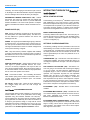
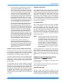
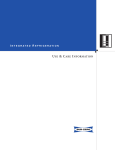
UNOCCUPIED HEATING SETPOINT - (60°F) - Identifies the
Unoccupied Heating Setpoint. It controls Unoccupied heating
with the Space Sensor.
UnOcc.
Htg.
Occ.
Htg.
Occ.
Clg.
UnOcc.
Clg.
FIGURE 2 - SEQUENCE OF SETTING THE SET POINTS
The control will attempt to correct wrong temperature overlap
settings; for example, if a change is made that would put
Occupied Heating above Occupied Cooling, the Occupied
Cooling setting will change to stay above the heating setpoint.
OCCUPIED HEATING SETPOINT - (68°F) - Identifies the
Occupied Heating Setpoint. Its relationship to the related setpoints is as defined in the Unoccupied Heating Setpoint paragraph above.
UNOCCUPIED COOLING SETPOINT - (85°F) - Identifies the
Unoccupied Cooling Setpoint.
OCCUPIED COOLING SETPOINT - (72°F)
Occupied Cooling Setpoint.
Identifies the
SUPPLY AIRTEMP (SAT) ALARM SETPOINT FOR COOLING - (0°F) - If the SAT does not drive below this setpoint
when all stages of compression are operating and 10 minutes
has elapsed since the last compressor was energized, the
control will declare a Cooling SAT Failure Alarm.
Unitary Products Group
The alarm is written to the Error History Buffer. In networked
applications, the alarm flag is readable via the network.
The alarm will reset automatically if the SAT decreases below
the setpoint (the alarm condition no longer exists), or when a
compressor is turned off (the control does not request all
compressors operate). The SAT Alarm Setpoint for Cooling
can be adjusted from 50°F - 80°F. If the value is set to 0°F
(default) this feature is disabled.
Before the control declares an error, it will read the OAT and
the Economizer position. If the OAT is more than 20°F
warmer than the setpoint and the Economizer is open more
than 20%, the control will close the Economizer for 10 minutes and then read the SAT. If the SAT falls below the setpoint, the control will declare an Economizer Minimum
Position alarm. The control will keep the Economizer closed
and finish the Cooling mode. After the Cooling mode has
been satisfied, the control will move the Economizer back to
the minimum position.
SUPPLY AIR TEMP (SAT) ALARM SETPOINT FOR HEATING - (0°F) - The SAT must rise above this setpoint when all
stages of heating are operating and 10 minutes has elapsed
since the last stage was energized. If this does not happen,
the control will declare a Heating SAT Failure Alarm. The
alarm is written to the Error History Buffer. In networked applications, the alarm flag is readable via the network. The alarm
will reset automatically if the SAT increases above the setpoint (the alarm condition no longer exists), or when a heating stage is turned off (the control does not request all heat
stages to operate).
The SAT Alarm Setpoint for Heating can be adjusted from
70°F - 120°F. If the value is set to 0°F (default) this feature is
disabled.
Before the control declares an error, it will read the OAT and
the Economizer position. If the OAT is more than 20°F colder
than the setpoint and the Economizer is open more than
20%, the control will close the Economizer for 10 minutes and
then read the SAT. If the SAT rises above the setpoint, the
control will declare an Economizer Minimum Position alarm.
The control will keep the Economizer closed and finish the
Heating mode. After the Heating mode has been satisfied,
the control will move the Economizer back to the minimum
position.
UNOCCUPIED OVERRIDE TIME PERIOD - (60 min) - The
Unoccupied Override Time Limit function will determine how
long the unit will operate in the Unoccupied Override mode
when the Override button is pressed on the Space Sensor.
Once the Unoccupied Override mode is initiated, it will continue until the programmed Unoccupied Override Time Limit
is reached. The Override mode cannot be cancelled by, for
example, a change of state of the Occupied input to ON
(occupied) and then back to OFF (unoccupied).
6
97585-UAI-A-1004
This parameter is adjustable from 0 to 240 minutes. The
default is 60 minutes.
SEQUENCE OF OPERATION FOR Intelli-Comfort ™
CONTROLS
If the control senses this input along with a Y signal, it will not
turn on the compressors and it will run the Heating mode.
Heating takes priority over cooling.
This chapter describes the many control modes of operation
for Intelli-Comfort ™. Because of the narrative and detailed
descriptions contained in this section, you should scan this
chapter and become familiar with the primary topics. Then,
use this chapter as a reference whenever a more detailed
understanding of a particular mode is needed.
FAN ON MODE WITH THE SENSOR OPTION - (ON) When this option is turned ON, the supply fan will continue
running when the zone sensor based temperature control is
satisfied. This option applies only in systems using a zone
sensor and only in Occupied mode. With this option turned
OFF, or in Unoccupied mode, the fan will go off when the
zone sensor based temperature control is satisfied and will
go on only when there is a call for heating or cooling. Turning
this option ON is an equivalent of selecting fan ON (rather
than AUTO) in systems with a thermostat. In a thermostat
system, the fan control follows the thermostat's G signal. In
sensor systems and in the Occupied mode, the fan control
follows the Fan ON Mode option.
SPACE SENSOR ENABLE - (OFF) (INTERNALLY SET) The control will use this input if it detects the device.
RAT SENSOR ENABLE - (OFF) (INTERNALLY SET) - The
control will use this input if it detects the device.
DEMAND VENTILATION (ON) - Setting this parameter on
tells the control to expect a signal from a 0-10VDC CO2 sensor. The default setting for CO2 is 1,000 ppm.
DEMAND VENTILATION SETPOINT - (1000 ppm) - Identifies the maximum Indoor Air Quality (IAQ) level that the control will allow. It is adjustable from 700ppm to 1500ppm.
IAQ SENSOR RANGE - (5,000 ppm) - Identifies the full
range is for a specific IAQ sensor. It can be changed from 0
to 10,000ppm.
COOLING MODE ENABLE (ON) - Identifies if the control has
Cooling Available (Mode Switch). If this option is turned off,
cooling operation is disabled. Note that this parameter does
not affect cooling operation in Comfort Ventilation mode.
HEATING MODE ENABLE - (ON) - Identifies if the control
has Heating Available (Mode Switch). If this option is turned
off, heating operation is disabled. Note that this parameter
does not affect heating operation in Comfort Ventilation
mode.
SPACE SETPOINT OFFSET - (3°F) - The Space Setpoint
Offset is the +/- value the control will use to offset the Space
Setpoint when the slidebar Space Sensor is used. For example, if the Space Setpoint Offset value is set to 3.0°F, shifting
the slidebar all the way in minus direction will decrease the
Space Setpoint by 3.0°F and shifting it all the way in plus
direction will increase the Space Setpoint by 3.0°F. It is
adjustable from 0°F to 5°F.
7
Keep in mind, with digital controls interlocking between control modes is common and easily achieved. Also, by the very
nature of digital control programming, many simultaneous
rules can be implemented because they generally require
only software programming and very little peripheral hardware. This reduces the costs associated with manufacturing
and servicing equipment with this level of interacting features
but you can’t see the status of interlocked rules as you can
with discreet relays.
Several control modes will override other modes of operation.
For example; The Demand Ventilation (or, Indoor Air Quality)
control may override Comfort Ventilation / Economizer control
and drive the OA dampers above the established minimum
position. The Excessive SAT control will override all temperature control modes, Economizer mode, and compressor operation as well. If you suspect that a problem exists with the
economizer, or the compressors are locked out when no
alarms are set, verify that one of the control modes is not
overriding the normal mode of operation or the operation you
might expect to see.
AIR PROVING SWITCH - When the control starts the supply
fan, it waits 90 seconds to check for closure of the Air Proving
Switch. If the APS does not close, the control will turn off all
outputs and flag an alarm, and flash an alarm on the display.
It will retry the Fan output every 30 minutes for three
attempts. If after three attempts it still cannot qualify the Fan,
it will alarm and lock all heating and cooling operation out. If
the switch closes after an alarm has been flagged, the control
will resume normal operation and clear the active alarm.
After the control has turned off the fan, it will wait 90 seconds
and verify that the switch opens. If the switch does not open
after 90 seconds, the control will flag a failed switch and flash
the alarm. On the next startup, the control will stage up equipment normally.
This switch-closed failure mode of the Air Proving Switch can
only be detected with the Supply Fan off. It is important to
detect because it effectively disables the fan failure alarm
checking while fan is running, described in the paragraphs
above. Those checks would always pass as the switch would
remain closed. In networked applications, the error flag is
readable by the network. The alarm will automatically reset
after the problem that caused it has been corrected.
Unitary Products Group
97585-UAI-A-1004
When the control is running the fan and the APS has already
been proven, and then it opens, the control will wait 2 seconds before shutting down heating, cooling, and locking out.
It will alarm and retry as if it happened during start-up.
FAN DELAYS - There are separate Fan ON and OFF delay
periods for heating and cooling, to reduce the momentary
change in SAT.
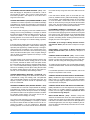
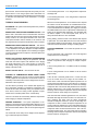
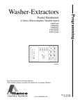
COMFORT VENTILATION MODE
High Supply Air Setpoint
Economizer Control Setpoint
(Middle of SAT Control Band)
SAT Control Band
(Gray Area)
Low Supply Air Setpoint
off and the SAT would be allowed to float until the space temperature control loop again generates a call for cooling or
heating. The supply fan may be kept on during the “satisfied”
periods, or may be turned off, depending on thermostat settings, or “Fan ON mode with the Sensor” option setting. If
Comfort Ventilation is selected, it will take priority over supply
fan control and keep it running during the “satisfied” periods,
when there is no call for heating or cooling.
The Comfort Ventilation mode is used to optionally replace
the uncontrolled, floating SAT situation during the “satisfied”
periods with a “loose” SAT control in a fairly wide temperature
band (between specified Comfort Ventilation Upper Setpoint
and Comfort Ventilation Lower Setpoint). This may require
some additional energy, but improves space comfort (e.g.
instead of bringing a very hot and humid ventilation / outdoor
air into space during the “satisfied” periods, the ventilation air
temperature is “trimmed” to be within the specified SAT control band).
Comfort Ventilation mode terminates when there is a call for
heating or cooling from the space temperature control.
•
FIGURE 3 -COMFORT VENTILATION ECONOMIZER
CONTROL
Comfort Ventilation is a control mode that uses the economizer to modulate SAT. Where possible, the economizer will
modulate the outside / return air mix to keep SAT within the
upper and lower Comfort Ventilation setpoints. The control
will modulate the economizer, and energize cooling or heating, to keep SAT within the Comfort Ventilation setpoints,
even though space temperature may be satisfied. For example, minimum economizer position can take SAT out of the
Comfort Ventilation range, requiring heat or cooling that the
thermostat isn’t calling for.
The result of comfort ventilation control is less variation of
SAT, and fewer on-off cycles of mechanical cooling or heating.
If turning off a cooling stage raises SAT above the upper setpoint, but leaving it running will take SAT below the lower setpoint - then the compressor is left on, and warmer outside air
is brought in to raise SAT to the lower setpoint to keep a compressor from cycling off. Similarly, if leaving a heat stage on
will raise SAT above the Upper setpoint, the control will leave
heat on and modulate cooler outside air into the airstream to
maintain proper SAT.
The Comfort Ventilation temperature-band minimum width is
five degrees. Comfort Ventilation high and low setpoints will
be within the Cooling Upper and Heating Lower setpoints.
Without using the Comfort Ventilation mode where available,
when the space temperature control loop is satisfied (zero
demand), all cooling and/or heating stages would be turned
Unitary Products Group
•
•
Comfort Ventilation can be used only on units
equipped with an Economizer.
Comfort Ventilation only operates in an Occupied
mode.
“Comfort Ventilation Mode” must be set to ON
(default setting is OFF).
The modulating range of the economizer dampers are limited
by a specified Economizer Minimum Position and by a specified Comfort Ventilation Maximum Economizer Setpoints.
The Economizer capability to control SAT may be further limited in case the Demand Ventilation Operation is enabled and
overrides the economizer to a more-open position in order to
satisfy space IAQ requirements. The values of “Comfort Ventilation Upper Setpoint” and “Comfort Ventilation Lower Setpoint” would typically be set such that they are centered
around an expected return air temperature. The band
between the two setpoints should be set wide enough so that
SAT changes due to staging / destaging compressors, or
heating stages, can be compensated for by the economizer
control so that staging / destaging is minimized. Also, a wider
band minimizes use of additional energy during unit’s “satisfied” periods.
ECONOMIZER CONTROL DURING COMFORT VENTILATION - Economizer control uses a Proportional-Integral (PI)
control algorithm that maintains SAT within the specified SAT
band by modulating the economizer dampers. The PI algorithm setpoint is calculated as a midpoint between the programmed "Comfort Ventilation Upper Setpoint" and "Comfort
Ventilation Lower Setpoint". As the controller uses outside air
to maintain the SAT at the setpoint, it must be capable of selfconfiguration for Direct or Reverse action, depending on the
relationship of the OAT to the specified SAT control band:
8
97585-UAI-A-1004
•
•
•
If the OAT is below the specified SAT band low setpoint ("Comfort Ventilation Lower Setpoint"), the
action is Direct Acting. In this case, the economizer
control can lower the SAT temperature just by opening the economizer damper and using more outdoor
air. However, if the economizer algorithm cannot
prevent the SAT from dropping below the bottom
control band limit by closing the economizer damper
to its programmed minimum position, one or more
heating stages may need to be turned on. Similarly,
if the economizer algorithm cannot prevent the SAT
from increasing above the top control band limit, one
or more compressors may need to be turned on.
CONTROL OPERATION
If the OAT is above the specified SAT band high setpoint ("Comfort Ventilation Upper Setpoint"), the
action is Reverse Acting. In this case, the economizer control can increase the SAT temperature just
by opening the economizer damper and using more
outdoor air. However, if the economizer algorithm
cannot prevent the SAT from increasing above the
top control band limit by closing the economizer
damper to its programmed minimum position, one or
more compressors may need to be turned on. Similarly, if the economizer algorithm cannot prevent the
SAT from dropping below the bottom control band
limit by opening the economizer damper, one or
more heating stages may need to be turned on.
ECONOMIZER MODE
If the OAT is within the SAT control band, i.e.
between the programmed "Comfort Ventilation
Upper Setpoint" and "Comfort Ventilation Lower Setpoint", the economizer damper is driven to the fully
open position. In this case, no other control action
needs to be taken to maintain the SAT within the
specified control band.
STAGING CONTROL DURING COMFORT VENTILATION
The economizer control alone may not be able to maintain
the SAT within the specified control band. A separate staging
control algorithm supplements the economizer control and
will stage heating, or mechanical cooling as necessary.
If the SAT increases above the "Comfort Ventilation Upper
Setpoint" for more than 5 minutes, the control will destage a
heating stage, or add a compressor. The control will repeat
this process every 5 minutes until the SAT gets back to within
the control band.
If the SAT drops below the "Comfort Ventilation Low Supply
Air Setpoint" for more than 5 minutes, the control will destage
a compressor, or add a heating stage. The control will repeat
this every 5 minutes until the SAT gets back to within the control band. As the heating stages, or compressors are staged,
or destaged, the economizer control continues using the
economizer damper to "trim" the effect of the staging and to
maintain the SAT as near the middle of the SAT control band
as possible.
9
The paragraphs below identify control modes of operation
and provide an overview of control methods in all modes. The
modes include Occupied and Unoccupied Heating and Cooling, and differ depending on the method used to control zone
temperature. The heating vs. cooling modes are entered
under control of the scheduling, and the control algorithm
detecting zone cooling or heating demand. The "occupied"
vs. "unoccupied" modes are controlled by an internal time
clock. If a thermostat input is connected, it takes priority over
the space sensor algorithms.
With a cooling demand and when free cooling is available
("economizer suitable"), the SAT controlled by the economizer control algorithm (see section Economizer Operation
later in this manual) and the control determines (by 1st and
2nd stage calls) the active economizer SAT setpoint. When
the control is satisfied (Y1=OFF, Y2=OFF), then the unit
either shuts down (if G=OFF) after the specified supply fan
overrun time, or only the supply fan continues to operate if
the Fan On Option is on.
NOTE:
During Economizer operation using "Economizer
First Stage Setpoint" for SAT control, one or more
compressors may be running in addition to economizer damper partially, or fully open to provide
free cooling. The number of compressors running
will mainly depend on outdoor air temperature.
Therefore, when the thermostat is satisfied and
shuts down the cooling, it may be turning off more
than one compressor (after compressor minimum
run time expires).
This is acceptable and is not expected to occur frequently.
See the section on Comfort Ventilation. If the outdoor air condition is such that more than one compressor is needed in
addition to free cooling, the Economizer mode is likely to terminate and the unit will switch over to mechanical cooling
only.
OPERATION FOR HEATING WITH W1 AND W2,
OUTPUTS TO THE Simplicity ® BOARD
W1 AND W2 outputs are available on the Simplicity ® IntelliComfort ™ board.
Three minute Minimum Run Time and two minutes minimum
off time applies to all heat stages.
SENSOR OPERATION
Typically, a space sensor should be installed. The only
exception should be for servicing or troubleshooting the unit.
A service person may hardwire the thermostat inputs to
check the equipment operation even if the unit is using a
Unitary Products Group
97585-UAI-A-1004
space sensor. The thermostat input will have priority over the
Space Sensor. A unit using a space sensor will switch to a
thermostat control strategy automatically if a thermostat input
is detected and switch back if the thermostat is no longer
detected.
A zone heating demand of -1.5°F will generate a request for
first stage heat.
TYPES OF SPACE SENSORS
When the zone temperature is -0.1°F below the zone setpoint
for at least 1 minute, the transition to a satisfied state occurs,
the heating stops and the supply fan either continues running,
or is turned off after the fan off delay. The supply fan control in
the satisfied state and in the occupied mode is determined by
setting of the programmable parameter "Fan ON Mode with
the Sensor Option". In the unoccupied mode, the fan is
always turned off when the zone is satisfied.
NO SENSOR- The system will internally detect the presence
of space sensors.
SENSOR WITH UNOCCUPIED OVERRIDE BUTTON - This
Sensor has a Thermistor and an Override button that when
pushed, will place the unit in Unoccupied Override (Occupied
mode) mode for the Unoccupied Override Time. Once the
Unoccupied Override mode is initiated, it will continue until
the programmed Unoccupied Override Time Limit is reached.
SENSOR WITH SPACE SETPOINT ADJUST - This Sensor
has a slider potentiometer on it that represents (as a default)
+/- 3°F adjustment to the Space Setpoint. The Space Setpoint
Offset option. If the unit appears to be controlling at a higher
or lower temperature than the setpoint, check the Space Setpoint Adjust slider.
SUPPLY FAN CONTROL WHEN USING A ZONE SENSOR
- In the Occupied mode, setting of the parameter "Fan ON
mode with the Sensor Option" will determine if the Supply
Fan is ON continuously or is in "Auto" mode (i.e. cycles with
the heating/ cooling cycles). In Unoccupied mode, the fan is
always in the Auto mode.
SUPPLY FAN OFF DELAY - Uses minimum off time.
CONTROL OF COMPRESSORS WHEN USING A ZONE
SENSOR - A Minimum run time of one to ten minutes [default
= three ] applies to all compressors. The minimum run time is
necessary to ensure that the oil in the refrigerant circuit circulates back to the compressor.
The Anti Short Cycle delay of five minutes OFF applies any
time compressor operation is terminated. Compressors are
turned ON and OFF individually during CV operation with a
zone sensor, where the cooling control algorithm is implemented in the controller (rather than in a thermostat).
There is a minimum 30 second delay between compressors
when bringing on multiple compressors.
HEATING OPERATION - The space temperature is controlled to a programmed Unoccupied Heating Setpoint, or to a
programmed Occupied Heating Setpoint, as determined by
the internal schedule and the state of the Occupied flag from
a BAS.
The control will use as many as two stages of heat, depending on what heat option is installed.
Unitary Products Group
A zone heating demand of -2.0°F will generate a request for
second stage heat.
During heating, the SAT control to the selected SAT setpoint
is performed. Two minute Minimum Run Time and Anti Short
Cycle delays applies to all heat stages. There is also a delay
of at least one minute between turning on heating stages.
COOLING OPERATION - The control will operate as a twostage unit.
On two compressor units, compressor one is first stage and
compressor two is second stage.
The control uses a minimum 30-second compressor delay
between compressors when bringing on multiple compressors.
A zone cooling demand of 1.5°F initiates a call for first stage
cooling.
A zone cooling demand of 2.0°F initiates a call for second
stage cooling.
If the unit has a demand greater than 1.5°F but less than
2.0°F, the control will turn on stage one and initiate a 5minute timer. If after 5 minutes the Space temperature is not
moving toward the Setpoint, the control will turn on stage two
and wait 5 minutes.The control will turn off the second stage
compressor with a 30-second delay between them when the
demand reaches 0.5°F. The control will continue operating
first stage until the Space temperature reaches the Setpoint
and then it will turn off the stage one compressor.
If the unit starts with a demand greater than 2.0°F, the control
will initiate first stage and wait 5 minutes. The control will continue operating first stage until the Space temperature
reaches the Setpoint and then it will turn off the stage one
compressor. If after 5 minutes the Space temperature is not
moving toward the Setpoint the control will initiate stage two
and wait 5 minutes.The control will turn off the second stage
compressor when the demand reaches 0.5°F with a 30 second delay between them. The control will continue operating
first stage until the Space temperature reaches the Setpoint
and then it will turn off stage one.
10
97585-UAI-A-1004
There are two different SAT control algorithms, one used
when free cooling is available (economizer operation) and the
other one for mechanical cooling only. These two SAT control
algorithms are described in the Occupied Cooling section
below. Since the economizer is not active in Unoccupied
mode, this will be restricted to mechanical cooling.
Economizer dampers are also controlled in certain situations
to perform ”economizer loading” - which minimizes SAT temperature swings resulting from turning cooling or heating
stages on / off. This function is separate from normal economizer operation and is described at the end of this section.
WHEN IS THE ECONOMIZER OPERATION USED?
CONTROLLING EXCESSIVE SAT (SUPPLY AIR
TEMPERATURE)
This is required in cooling operation in order to prevent "slugging" and damage to the compressors. Some rooftop units do
not use accumulators on compressor intake, and liquid refrigerant could enter the intake of a compressor in case of a low
heat transfer on the evaporator coil. In heating operation, the
Excessive SAT control is not used.
SAT CONTROL CONFIGURATION
SAT control for cooling is configurable to enable or disable
(on/off). The default setting for cooling is ON. The user is not
normally expected to turn this mode OFF, but the possibility
of turning it OFF is provided mainly for troubleshooting purposes.
SAT CONTROL FOR COOLING
This control has priority over any other zone temperature or
SAT control and is used at all times. The Excessive SAT Control state is entered any time the SAT drops below the trip
point.
While in this state, the control will continue monitoring the
SAT and turning off compressors any time the SAT drops
below the trip point. There is a 2 minute time delay between
compressor trips in cases when the SAT drops below trip
point. This assures that multiple compressors will not be
turned off simultaneously.
ECONOMIZER LOADING OPERATION DURING AN
EXCESSIVE SAT FOR COOLING:
If the rooftop unit is equipped with an economizer, and free
cooling is available (“economizer suitable”), then the Economizer Operation as specified in this section will be used in the
following operation modes:
MINIMUM VENTILATION POSITION SETTING
The minimum position setting represents the minimum opening of the outdoor air damper (% open). This setting will be
maintained any time the unit is in Occupied mode. The minimum position setting will be determined by an “Economizer
Min Position” programmable parameter set by a computer
running the front-end software. The minimum position setting
will be ignored during the Unoccupied mode. During the
Unoccupied mode, the minimum position is 0% (the Economizer may not remain closed during the Unoccupied mode, in
case the temperature control to an unoccupied setpoint can
use Outside Air for free cooling).
MINIMUM POSITION DURING HEATING AND OCCUPIED
MODE
During heating while in Occupied mode, the economizer will
be at its programmed minimum position.
MINIMUM POSITION DURING COOLING AND OCCUPIED
MODE
During cooling while in Occupied Mode, the economizer may
be at its programmed minimum or may be modulated
between its minimum position and 100% open position by the
economizer control.
ECONOMIZER OPERATION
SAT SETPOINTS USED DURING COOLING WITH
ECONOMIZER OPERATION:
Economizer dampers allow mixing of outdoor and return air.
The dampers are coupled and controlled with a single actuator such that when the Outdoor Air damper is fully closed, the
Return Air damper is fully open (and vice versa). The position
of the Economizer dampers are controlled based on:
As long as the Economizer Operation is enabled and “free
cooling” is available, the economizer will be controlled (with,
or without any compressors running) to maintain the following
SAT setpoints: In CV cooling mode:
1.
Energy considerations (“free cooling”)
2.
Ventilation considerations (minimum Outdoor Air damper
position and Demand Ventilation)
3.
Space static pressure considerations (minimum Outdoor
Air damper position).
11
•
With a call for first stage cooling, a programmed
Economizer First Stage Setpoint. This setpoint is
programmable in the range of 40°F to 65°F, default
setting is 55°F
•
With a call for second stage cooling, a programmed
Economizer Second Stage Setpoint. This setpoint is
programmable in the range of 40°F to 65°F, default
setting is 50°F
Unitary Products Group
97585-UAI-A-1004
CRITERIA FOR ECONOMIZER SUITABLE DECISION SENSOR AVAILABILITY:
There are three different methods of deciding whether the
economizer is suitable:
•
Differential enthalpy (highest preference from
energy viewpoint)
•
Outside enthalpy (middle preference) and
•
Outside temperature method (lowest preference)
The choice of a method with highest preference is automatic
(“self-configuration”) based on availability of appropriate sensors. If a sensor fails or is unreliable, a fault is indicated and
the next highest preference method will be automatically
selected (“fault tolerance”).
There are two ON/OFF programmable parameters related to
the choice of an economizer method:
•
“OAH Sensor Enable”
•
“RAH Sensor Enable”
These parameters are set to reflect the installed sensors that
can be used by the “self-configuration” feature and control
sensor failure alarms.
The OAH sensor, if available, allows use of Outside Enthalpy
method for deciding on free cooling availability.
The RAH sensor, if available in addition to the OAH sensor,
allows use of Differential Enthalpy method for deciding on
free cooling availability.
See paragraphs OAH Sensor Enable and RAH Sensor
Enable in The Settable Parameters.
If the selected method is using an enthalpy, the enthalpy is
calculated in the controller from sensed temperature and
humidity of the respective air stream.
DIFFERENTIAL ENTHALPY METHOD: is set by parameter
and used only when sensors for Outdoor Air temperature,
Outdoor Air humidity, Return Air temperature and Return Air
humidity are all installed and reliable.
OUTSIDE ENTHALPY METHOD: will be configured by setting ON the parameter for the Outdoor Humidity Sensor
[OAH], and will be the default if the unit defined as Differential
Enthalpy cannot read the Return Air Humidity sensor.
OUTSIDE TEMPERATURE METHOD: will be self-configured
and used only when differential enthalpy or outside enthalpy
methods are not available, and sensor for Outside Air temperature is installed and reliable.
Economizer is suitable when OAT is less than SAT setpoint +
10°F. Use a 2°F differential on both sides of this limit. As the
Unitary Products Group
SAT setpoint value, use only one of the programmed 1st or
2nd stage economizer setpoints (depending on what cooling
stage is called), not any transient setpoints that may be used
temporarily during the staging process. Note that this rule
does not reflect any consideration of geographical location
and weather conditions, but rather reflects the average
expected SAT temperature drop obtained from DX cooling
stages, i.e. the highest outdoor air temperature that the DX
cooling can still reliably reduce to the SAT setpoint.
OUTSIDE ENTHALPY METHOD: Economizer is suitable
when OA Enthalpy is less than Outside Enthalpy setpoint and
OAT is less than OAT Economizer Enable Setpoint: Use a
2°F and 1 BTU/LB differentials respectively on both sides of
these limits. The Enthalpy number is a programmed parameter with a range of 22-40 BTU/LB, default 27 BTU/LB. The
Enthalpy Number can be viewed as the maximum outdoor air
enthalpy with which the outside air can still be considered
suitable for DX cooling, or, in comparison to the Differential
Enthalpy Method described below, as a “best guess” on
actual return air enthalpy, which in this method is not being
sensed. The temperature limit reflects the average expected
SAT temperature drop obtained from DX cooling stages.
DIFFERENTIAL ENTHALPY METHOD: Economizer is suitable when OA Enthalpy is less than the RA Enthalpy AND
OAT is less than SAT setpoint plus 10°F (+/- 2°F and 1
BTU/LB): Use a 2°F and 1 BTU/LB differentials respectively
on both sides of these limits. This is similar to the Outside
Enthalpy method, except instead of a programmed Enthalpy
Number, an actually sensed return air enthalpy is used.
SAT CONTROL WITH ECONOMIZER - If the economizer is
“suitable” (free cooling is available) and cooling is required,
the algorithm will be active and modulate economizer position
in order to control SAT to the active SAT setpoint. If the economizer is not suitable, the algorithm is deactivated and the
economizer is placed at its programmed minimum position.
The economizer control algorithm will typically be cycled
ON/OFF several times an hour under control of a zone thermostat, or a zone sensor. A zone control algorithm will activate the economizer algorithm when cooling is required, and
will switch between Economizer 1st and 2nd stage SAT setpoints, and will deactivate the economizer algorithm when the
zone is satisfied.
The PI economizer control algorithm is always active during
economizer operation (as long as economizer is “suitable”)
and will control SAT to an active (1st or 2nd stage) Economizer setpoint. This means that this control loop not only
modulates the Outside Air damper open to add free cooling
and decrease mixed air temperature to maintain SAT at setpoint, but, when DX cooling is running, also may modulate
the Outside Air damper closed to increase mixed air temperature (use more return air) and thus add load on the DX coil to
maintain SAT at setpoint (“economizer loading”). This represents a trade-off between energy and compressor cycling.
12
97585-UAI-A-1004
CONTROL OF COMPRESSORS WITH ECONOMIZER
TURNING ON OF COMPRESSOR #1: Never operate compression if the Economizer can maintain the SAT setpoint
with free cooling. If no compressors are on, and the economizer controller is saturated High, i.e. the economizer is
100% open and can no longer maintain the SAT setpoint by
just free cooling, the control will:
The same staging sequence is used for the remaining compressor (see below). Note that the standard 5 minute delay
before monitoring SAT after a compressor is turned on, or off,
applies here also.
TURNING ON COMPRESSOR #2: If the economizer controller is saturated High, i.e. the economizer is 100% open while
one or more compressors are running and the control can no
longer maintain the active SAT setpoint requested by the
zone control, the control will turn on compressor # 2:
NOTE:
The standard 5 minute delay before monitoring
SAT after a compressor is turned on or off.
The highest numbered running compressor is turned off
when the economizer controller is saturated Low.
modulated by the economizer dampers, in order to change
SAT and keep it at SAT setpoint when only compressor #1 is
running. This makes a trade-off between energy and compressor cycling and minimizes cycling of compressor #1. The
loading is done by the same type of PI control algorithm as
used in the normal Economizer operation.
The algorithm will be activated to do this function in following
conditions:
•
Economizer is “not suitable” (i.e. we are not in a normal Economizer mode)
•
The programmable option “Economizer Loading to
Control SAT” is ON
•
Only compressor #1 is running
The control algorithm in this case has the capability of automatically change from direct to reverse acting in response to
difference between OAT and RAT. When OAT is less than
RAT, the algorithm is direct acting, the algorithm changes to
reverse acting when RAT is less than OAT. This way,
the”loading” of the DX coil is correctly done with return, or
outdoor air, as appropriate, and there is no need to activate
this “loading” function only at higher outdoor air temperatures
(e.g. OAT > 60°F).
This method of turning compression off is considered better
than using the Excessive SAT Control - turning a compressor
OFF only if SAT reaches its specified trip point. If that method
was used and the Excessive SAT Control was not selected,
there would be no means for turning compressors off.
The algorithm controls SAT to its specified setpoint in control
modes where no SAT setpoint is specified (such as in Excessive SAT control state in cooling), to a fixed temperature
deadband of 50°F to 55°F.
NOTE:
NOTE:
The compressors also will be turned off when the
zone temperature control is satisfied.
A situation may arise when in Economizer Mode and one or
more compressors are required in addition to full available
free cooling in order to maintain the SAT setpoint, but Cooling
Lockout on OAT prevents the compressors use. This situation
may arise when the SAT setpoint is set very close to, or even
below the temperature set for Cooling Lockout on OAT - a relatively unusual case. If the OAT then increases above the
lockout setting while the call for several compressors exists,
the compressors will turn on with a delay between compressors.
ECONOMIZER LOADING OPTION - This is a user programmable option. It is automatically disabled if the unit does not
use an economizer. The on/off programming choice is common to both cooling and heating. The default setting is ON.
This programmable “Economizer Loading” function is used
only outside the normal Economizer operation.
During the Economizer operation, the “Loading” function is
always used and is an integral part of the Economizer control
algorithm.
ECONOMIZER LOADING OPTION IN COOLING: In cooling,
this function causes changes in mixed air temperature, as
13
As opposed to the PI algorithm used in economizer control, the PI algorithm used here for
economizer loading function does not need to utilize the High saturation state for any additional
control functions. Therefore no complications
arise when switching between direct and reverse
acting modes.
ECONOMIZER LOADING OPTION IN HEATING: In heating,
this function uses additional outside air, as modulated by the
economizer dampers, in order to decrease SAT when only
the first stage of heating is running and keep the SAT below
the programmed ”Economizer Loading Setpoint in Heating”.
This prevents the heat section from cycling on its internal
temperature limit safety switch, which is typically set about
10°F above the Economizer Loading Setpoint. A need for
economizer loading arises in Communicating Zoning System
applications (“VVT” systems) using supply air bypass when
heating load in the zones is low and a large amount of hot
supply air is bypassed back into return and mixed air temperature is very high. Economizer loading may also be needed
when supply air flow across the heat exchanger is lower than
expected (e.g. wrong setting of fan speed, plugged air filters).
A secondary benefit of economizer loading is an improvement in comfort as the supply air temperature is more stable
and cycling of the unit is minimized.
Unitary Products Group
97585-UAI-A-1004
The economizer loading minimizes cycling of heating stage
#1 and makes a trade-off between energy and the benefits
described above.
and the economizer is closed to its minimum position during
heating.
DEMAND VENTILATION
The Economizer Loading in heating option requires a SAT
sensor that can sense SAT in heating mode. A sensor placed
downstream of the heating stages. Such a sensor is provided
only as a field-installed accessory, on units equipped with
heating stages. The SAT sensor that is factory-installed can
be used for cooling mode only. If a field-installed sensor is
added, it will replace the factory-installed one and will then be
usable for both heating and cooling modes.
The loading is done by the similar control algorithm as used
in the normal economizer operation. The algorithm is activated to do this function in following conditions:
•
Heating mode
•
The programmable option “Economizer Loading to
Control SAT” is ON
•
Only heating stage #1 is running
The control algorithm in this case has a capability to automatically change from direct to reverse acting in response to difference between OAT and RAT. When OAT is less than RAT
the algorithm is direct acting, when OAT is greater than RAT
the algorithm is reverse acting.
This way, the “loading” of the heating stage is correctly done
with return or outdoor air as appropriate, and there is no need
to activate this”loading” function only in some specific range
of outdoor air temperatures (e.g. OAT > programmed first
heating stage trip point minus 50°F).
NOTE:
Provision for direct vs. reverse acting switching is
a feature of the control algorithm and the algorithm could be implemented as direct acting only
in order to simplify implementation and save code
space. The situation when economizer loading in
heating is required while OAT greater than RAT is
unlikely and if it should occur, the difference
between OAT and RAT is negligible in comparison
to the SAT control setpoint. The Economizer
Loading function in heating controls SAT to a fixed
temperature deadband of programmed “Economizer Loading Setpoint in Heating” and 5°F below
this setpoint (the setpoint is programmable
between 100°F - 195°F, default is 160°F).
In units that use hydronic heat, the Economizer Loading function may be enabled in order to be used for cooling. The
on/off programming choice for this function is common to
both cooling and heating. It is important to ensure that the
programmed value of the “Economizer Loading Setpoint in
Heating” is set higher than the value of “Hydronic Heat First
Stage Setpoint”. That assures, in normal conditions, the
Economizer Loading function in heating is effectively disabled
Unitary Products Group
Demand Ventilation Operation control mode is self-configuring for the use of an Indoor Air Quality (IAQ) sensor - it will
automatically detect that an IAQ sensor is connected and use
it any time the IAQ sensor input indicates an IAQ level of 200
ppm, or higher.
NOTE:
Due to the self-configuration operation, an error
due to IAQ sensor failure can be indicated only in
case the IAQ sensor fails during normal controller
operation. If the IAQ sensor fails or is removed /
disconnected during a power-off condition (e.g.
during servicing of the unit while the control is not
powered), the control will, on power up, self configure without the IAQ sensor and no error indication is provided.
When the IAQ sensor is detected as available, the control will
use the Demand Ventilation Setpoint to control the IAQ levels
in the building by modulating the Economizer more open.
The Demand Ventilation will operate in units equipped with an
Economizer any time the option is turned ON and the control
is in Occupied mode. The Demand Ventilation Operation is
applicable in heating or cooling mode and will modulate the
Economizer damper, if necessary, from its programmed minimum position or from its modulated position as defined in the
Economizer Operation section.
An appropriate control algorithm is used to accomplish this
function. This algorithm is a "step-and-wait" type, with the
step size calculated as a function of offset between the
Demand Ventilation Setpoint and the current IAQ level, and
with a fixed "wait", or sampling time. This algorithm is activated whenever the IAQ level exceeds the setpoint and will
override the economizer position more open, as needed, up
to a pre-programmed Maximum Economizer Position for
Demand Ventilation. The algorithm is deactivated, and the
previous, normal mode of economizer position control
resumes when the IAQ level becomes 50 ppm lower than the
setpoint.
The programmed "Maximum Economizer Position for
Demand Ventilation" is used to minimize the possibility that
the Demand Ventilation may open the Economizer damper
too much, such that at high OA temperatures, even combined
cooling output of all compressors would not provide sufficient
cooling. As a rule of thumb, all compressors combined
achieve approx. 20°F SAT decrease. Similarly, at fairly low
OA temperatures, the combined output of all heating stages
may not be able to provide sufficient heating. This Economizer max. position limit is simpler to implement than a
closed loop SAT low-limit control that would operate with a
programmed high-limit for cooling and a programmed low
limit for heating.
14
97585-UAI-A-1004
NOTE:
An added measure of protection against excessive SAT during Demand Ventilation Operation is
provided by Supply Air Alarm Setpoint for Cooling
and Supply Air Alarm Setpoint for Heating, and
the control function associated with these setpoints (see the respective paragraphs in the
Option Operation section earlier in this document).
SCHEDULING OPERATION
The Simplicity ® Intelli-Comfort ™ refers to its clock and internal calendar to perform scheduling operations.
COMPRESSOR STATUS MONITORING
Compressor status is monitored using three separate 24 VAC
circuits that monitor: low pressure, high pressure, and Evaporator Freeze Thermostats. If any of the three safeties is in
error, the trip is noted in the alarm history.
The Low Refrigerant Pressure Switch is Normally Open.
When the compressor is off and refrigerant pressure equalized, the switch under normal conditions is expected to be
closed. However, in cold ambient operation, it may stay open
and close only after the compressor starts up.
If an error is detected for a compressor, that compressor’s
output is turned off. Note that the controller executes the
application code once every 32ms, with a 30 second startup
delay and 5 second minimum error time on low pressure. The
control then declares a "Compressor Locked Out on Trip"
alarm. The alarm is written to the Error History Buffer.
NOTE:
The compressor lockout works as an override of
the output of the staging algorithm for cooling control. For example, the cooling control may ask for
compressor #2 which is locked out, and as this
request does not generate additional cooling.
Following are errors that are entered into the error history buffer:
•
•
•
•
•
•
•
Compressor locked out on safety chain trip
Supply fan failure
Heating SAT failure
Cooling SAT failure
SAT,RAT,OAT,IAQ, ST, or RH failure
Dirty Filter alarm
Bad Air Proving Switch
SENSOR FAILURES AND DEFAULT OPERATION
A failure of SAT RAT, OAT, IAQ, Space Temperature, or an
outside or return air Relative Humidity sensor will generate a
common error. A failure of the Duct Static or Building Pressure sensor will generate another common error. The errors
will be indicated by a Status LED. The errors will be written to
the Error History Buffer. In networked application, the error
flag will be readable by the network. The error indication of a
sensor failure will continue until the problem is corrected
and will automatically terminate when the sensor is again
detected as reliable. If the unit is shut down as a result of a
sensor failure, the alarm must be reset after the sensor problem has been corrected, by resetting the controller, or reset
command issued by the Front-end software.
SAT SENSOR
If the SAT sensor fails, the Economizer, excessive SAT control will be disabled. The Control will then continue a "limp
along" operation under zone sensor control. RAT Sensor
If the RAT sensor fails, it will default to single enthalpy or Dry
Bulb operation.
OAT SENSOR
UNITS WITHOUT ECONOMIZER: If the OAT sensor fails the
control will not run any algorithm that requires that data.
FAILURE MODES AND DEFAULT OPERATION
UNITS WITH ECONOMIZER: All Economizer Operation will
be disabled. This is because OAT sensor is the most essential sensor in determining availability of free cooling. Even if
the unit is equipped with Outside RH sensor and controller
could calculate Outdoor Enthalpy, the OAT sensor is still
essential in that calculation. The Economizer will only modulate to the Minimum Position when the Fan is operating and
the control is in Occupied Mode.
ERROR HISTORIES
OUTSIDE AIR RELATIVE HUMIDITY SENSOR
The control will store the latest five errors in a FIFO manner
in EEPROM, for later display. As the control collects errors, it
will overwrite the oldest error after the history buffer becomes
full.
If the OAH sensor fails, the control will only use the OAT sensor to determine if Free Cooling is available. The control will
self-configure to Outside Temperature Method (see also
Economizer Operation section earlier in this document).
STATUS LED
The Status LED mounted on the controller PC board will flash
faster than the once a second flash indicating an Alarm. You
will need to connect a computer to pull out the specific Alarm.
15
Unitary Products Group
RETURN AIR RELATIVE HUMIDITY SENSOR
The control will self-configure to Outside Enthalpy Operation.
SPACE TEMPERATURE SENSOR
When the space temperature sensor fails the control will
check if the RAT sensor is present. If it has a RAT sensor, the
control will use it as a backup and continue temperature control to the active space temperature setpoint. If there is no
RAT Sensor, the control will shut down all outputs. If the
detected sensor failure is a short circuit, the error can be
declared only if the short persists for several minutes, in order
to distinguish a sensor failure from a short caused by somebody pushing on Unoccupied Override button.
IAQ SENSOR
If the IAQ sensor fails, Demand Ventilation mode is de-activated.
Buffer. In networked application, the error flag will be readable via the network.
SUPPLY FAN FAILURE
The conditions under which this failure is declared, and the
follow-up actions of the control when this error occurs are
described in a paragraph on Air Proving Switch Operation
earlier in this document. The error will be written to the Error
History Buffer. In networked application, the error flag will be
readable via the network.
COMPRESSOR SAFETY CHAIN TRIP
The conditions under which this failure is declared, and the
follow-up actions of the control when this error occurs are
described in a paragraph on Compressor Status Monitoring
earlier in this document. The error will be written to the Error
History Buffer. In networked application, the error flag will be
readable via the network.
SYSTEM ERRORS
DIRTY FILTER ALARM
HEATING SAT FAILURE
The conditions under which this failure is declared, and the
follow-up actions of the control when this error occurs are
described in a paragraph on Dirty Filter Switch (DFS) option
earlier in this document. The error will be written to the Error
History Buffer. In networked application, the error flag will be
readable via the network.
In Heating mode with all stages of heating energized, the SAT
must drive above the Supply Air Alarm Setpoint for Heating
within ten minutes or this SAT failure error will be activated.
The error will be written to the Error History Buffer. In networked application, the error flag will be readable via the network.
COOLING SAT FAILURE
In Cooling mode and all stages of compression are energized, the SAT must drive below the Supply Air Alarm Setpoint for Cooling within ten minutes or this SAT failure error
will be activated. The error will be written to the Error History
BAD AIR PROVING SWITCH ERROR
The conditions under which this failure is declared, and the
follow-up actions of the control when this error occurs are
described in a paragraph on Air Proving Switch Operation
earlier in this document. The error will be written to the Error
History Buffer. In networked application, the error flag will be
readable via the network.
Subject to change without notice. Printed in U.S.A.
Copyright © by Unitary Products Group 2004. All rights reserved.
Unitary
Products
Group
97585-UAI-A-1004
Supersedes: Nothing
5005
York
Drive
Norman
OK
73069