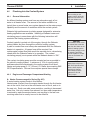
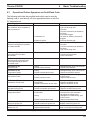
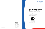
1
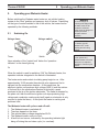
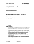
Coolant Heaters
Thermo 230.036
Thermo 300.066
Diesel - 24 Volts
Installation Instructions
Operating Instructions
07/2012
P/N 907507
Thermo 230/300
Contents
Contents
1. Introduction
1.1 General Description.........................................................................................................
1.2 Legal Provisions ..............................................................................................................
1.3 Meaning of Warning, Caution and Note ..........................................................................
101
102
102
2. Operating your Webasto Heater
2.1 Switching On....................................................................................................................
2.2 Switching Off....................................................................................................................
2.3 Engine Pre-heating..........................................................................................................
2.4 Boost Heating for Engine and Passenger Compartment ................................................
2.5 Operation with 7-Day Digital Timer Model 1531..............................................................
2.6 7-Day Digital Timer Programming and Operating Instructions........................................
201
202
202
202
202
204
3. Technical Data
3.1 Thermo 230/300 Heater Data..........................................................................................
3.1.1 Thermo 230/300 Heater Dimensions....................................................................
3.2 Coolant Circulation Pump Data .......................................................................................
3.2.1 Coolant Circulation Pump Dimensions .................................................................
301
302
303
303
4. Installation
4.1 General Information.........................................................................................................
4.2 Installation Location.........................................................................................................
4.3 Mounting the Heater ........................................................................................................
4.4 Exhaust Pipe Connection ................................................................................................
4.5 Combustion Air Supply ....................................................................................................
4.6 Plumbing Into the Coolant System ..................................................................................
4.6.1 General Information ..............................................................................................
4.6.2 Engine and Passenger Compartment Heating .....................................................
4.6.3 Example of a Heater Installation in a Bus.............................................................
4.7 Fuel System.....................................................................................................................
4.7.1 General Description ..............................................................................................
4.7.2 Fuel Supply ...........................................................................................................
4.7.3 Fuel Filter ..............................................................................................................
4.8 Wiring Connections .........................................................................................................
4.8.1 General Information ..............................................................................................
4.8.2 Timer and Switch Connections .............................................................................
4.8.3 Timer and Switch Installation................................................................................
4.8.4 Wiring Diagram - with Switch ................................................................................
4.8.5 Wiring Diagram - with 7-Day Digital Timer Model 1531........................................
4.9 Initial Operation................................................................................................................
401
401
401
401
402
403
403
403
406
407
407
407
408
409
409
409
409
410
411
412
I
Thermo 230/300
Contents
5. Maintenance of the Heater
5.1 Annual Maintenance........................................................................................................
501
6. Basic Troubleshooting
6.1 General Information .........................................................................................................
6.2 Operational Failure Symptoms (Reading the flash code) ...............................................
6.2.1 Reading a Fault Code with 1531 “Comfort” Timer Installed ................................
6.2.2 Storing a Fault Code in Memory ...........................................................................
6.3 Operational Failure Symptoms via Fault/Flash Code......................................................
6.4 Reading and Removing Fault Codes Stored in Memory with PC Diagnostics Kit ..........
601
601
602
602
603
604
7. Warranty Policy
8.1 Warranty Policy................................................................................................................
801
List of Figures
101
201
301
302
303
304
401
402
403
404
405
406
407
408
409
410
II
Webasto Thermo 230/300 Heater ...................................................................................
7-Day Digital Timer – Model 1531 ...................................................................................
Thermo 230/300 Heater Dimensions ..............................................................................
Coolant Circulating Pump Assembly - U 4814 ................................................................
Coolant Circulating Pump Assembly - U 4851 ................................................................
Pump Operating Data - U 4851 .......................................................................................
Series Plumbing Circuit (Shown with heater installed)....................................................
Parallel Plumbing Circuit (Shown with heater installed) ..................................................
Engine Preheat/Boost Heating Circuit .............................................................................
Example of Heater Installation.........................................................................................
Fuel Standpipe Installation ..............................................................................................
Fuel Line Parameters ......................................................................................................
On/Off Switch...................................................................................................................
7-Day Digital Timer Model 1531 ......................................................................................
Wiring Diagram with Switch.............................................................................................
Wiring Diagram with Timer ..............................................................................................
101
203
302
303
304
304
404
404
405
406
407
408
409
409
410
411
Thermo 230/300
Contents
List of Tables
201
301
302
601
Digital Timer Instructions .................................................................................................
Thermo 230/300 Heater Data..........................................................................................
Coolant Circulation Pump Data .......................................................................................
Operational Failure Symptoms via Fault/Flash Code......................................................
204
301
303
603
PART # 907 507
Rev. 11.15.98
Subject to modification
III
Thermo 230/300
1
1.
Introduction
1.1
General Description
1
2
3
4
5
6
Combustion air fan
Motor
Electronic control unit
Electronic ignition coil
Ignition electrodes
Water pipes
7
8
9
10
11
12
Fuel nozzle
Temperature sensor
Overheat thermostat
Heat exchanger
Combustion chamber
Combustion air swirler
13
14
15
16
17
Introduction
Exhaust pipe
18 Fuel supply / return
Photo disc
19 Coupler
Flame detector
20 Combustion air intake
Fuel pump w/ solenoid valve
Combustion air adjusting shutter
Fig. 101: Webasto Thermo 230/300 Heater
The Webasto Thermo 230 and 300 Heaters for use on diesel powered transit buses and
coaches are designed to:
1. Preheat Engine block of liquid cooled engines to ensure reliable starting in cold weather and to
reduce cold start wear and emissions (white smoke).
2. Boost heating levels with the engine running. The heater will boost the heating system in cold
weather when an engine is running at light loads, even at high speeds or idling.
The heat rejection of modern diesel engines to the coolant, especially in buses, is often not
adequate to heat the vehicle’s interior.
3. Increase Driver Visibility in poor weather conditions by providing higher levels of heat for quick
defrosting/defogging of windshield and side glass.
101
1
Thermo 230/300
Introduction
1.2
Legal provisions
Heater installation must be performed in accordance with the manufacturer`s installation
instructions.
Any deviations from these instructions are only permitted with written approval from
Webasto Thermosystems.
Installations not complying with the installation instructions will release Webasto Thermosystems
from any product liability.
OEM installations must be approved by Webasto Thermosystems.
1.3
Meaning of Warning, Caution and Note
WARNING
This heading is used to
highlight that noncompliance with
instructions or procedures
may cause accidents
leading to severe injury or
death.
102
CAUTION
This heading is used to
highlight that noncompliance with
instructions or procedures
may cause damage to
equipment.
NOTE
This heading is used to
highlight and draw
specific attention to
information.
Thermo 230/300
2.
2
Operating your Webasto Heater
Operating your Webasto Heater
Before switching the Webasto water heater on, set vehicle heating
system to the “heat” position and open any shut off valves. Depending
on the type of control installed in the of the vehicle, the heater can be
operated by the following methods.
2.1
Switching On
Using a timer:
WARNING
Due to the danger of
poisoning and asphyxiation
the heater must not be
operated in enclosed
spaces such as garages or
workshops without
adequate exhaust
extraction.
Using a switch:
WARNING
The heater must be
switched “OFF” while
refueling and at fueling
stations.
Timer
Switch
Upon actuation of the “instant heat” button the “operation
indicator” on the timer lights up.
Or
WARNING
Do not operate any
Webasto heater in an area
where toxic or explosive
materials or fumes may be
present.
When the switch is used for switching “ON” the Webasto heater, the
operation indicator integrated in the switch is illuminated.
The heater motor and coolant circulating pump begin to run. After
approximately 10-25 seconds the solenoid valve opens and fuel is
sprayed into the combustion chamber. At the same time, the
electronic ignition coil produces high voltage (8000 V) and the mixture
of fuel and air in the combustion chamber is ignited by a spark
produced at the tip of the ignition electrodes. The flame is detected by
the photo cell, then the electronic ignition coil stops producing high
voltage and combustion continues by itself (spark on electrodes is only
required to ignite the flame). At this point the heater is working and
produces heat.
The Webasto heater will cycle on and off until:
1. The Webasto heater is switched off.
2. Time has elapsed on the timer.
3. The vehicle battery voltage drops below 20.0V.
4. The Webasto heater runs out of fuel.
5. A fault lock out occurs, indicated by the operating indicator light
being off during the cool down cycle (i.e. overheat).
201
2
2.2
Operating your Webasto Heater
Switching Off
When heating is no longer required, switch the Webasto heater off.
The solenoid valve interrupts the fuel supply, combustion stops and
the indicator light turns off. The Combustion air fan and the water
pump remain on for another 2-3 minutes (after run cycle) purging the
combustion chamber of any fumes.
2.3
Engine Pre-heating
1. Set the timer 30 min. to 1 hr. before you want to start engine. The
heater will start up at set time. (See timer operating instructions
beginning on page 203).
Or switch the toggle switch or “instant on” switch on your timer in
the vehicle dash to “ON”. The heater will start up.
2. When time is elapsed on your timer or engine preheat is no longer
required, switch the Webasto heater “OFF”. The heater will go
through the after-run cycle.
2.4
Boost Heating for Engine and Passenger
Compartment
1. Switch the toggle switch (or the “instant on” button of the timer) in
the vehicle dash to “ON”. The heater will heat the coolant to a
temperature of 185°F (85°C). Above this temperature only the
water pump will run.
2. When boost heating is no longer required, switch the Webasto
heater “OFF”. The heater will begin a brief after-run (cool-down)
cycle.
2.5
Operation with 7-Day Digital Timer Model 1531
The “Digital Timer with 3 time settings” permits the Webasto heater to
be switched on and off instantly, or automatically at 3 programmable
starting times.
The operating time of the heater can be pre-selected.
It is possible to program 3 different heating programs according to
your individual needs.
Only one preset starting time can be activated at any one time.
When the vehicle’s ignition is switched on, the current time of the day
and the day of the week are displayed.
202
Thermo 230/300
NOTE
Restarting the Webasto
during the after-run period
is allowed.
Thermo 230/300
2
Operating your Webasto Heater
Programmed Heater Operation
Three memory locations numbered 1 to 3 are available. Each memory
location can be assigned a given time together with the day of the
week.
Pre-selected Starting Times
The pre-selected starting time is the time at which the heater switches
itself on automatically.
We recommend that memory locations 1 and 2 be used for presetting
starting times within 24 hours of setting the timer.
Memory location 3 can be used for a starting time within the next 7
days of setting the timer.
Operating Time
The period of time during which the heater is in operation is referred to
as operating time. The heater remains in operation for as long as the
operating time has been preset.
Heater operation can be pre-selected for any time from as little as 1
minute to a maximum of 120 minutes (factory preset is 60 minutes).
Remaining Operating Time
The remaining operating time refers to the period of time the heater
still continues to remain in operation. It can only be changed while
heater is in operation.
NOTE
If the ignition is switched
off while the heater is in
operation, the remaining
operating time of 5
minutes flashes on the
display and the heater
continues to operate for
this period of time.
Setting the Digital Timer
After the power has been connected, all symbols on the digital display
are flashing. The time of the day and the day of the week must be set.
All flashing displays and symbols of the timer can be set by means of
the and buttons.
If the buttons are not pressed within 5 seconds, the currently displayed
time or function will be stored.
When the and buttons are pressed for more than 2 seconds, the
quick digit advance mode is activated.
Fig. 201: 7-Day Digital Timer – Model 1531
203
2
2.6
Operating your Webasto Heater
7-Day Digital Timer Programming and Operating
Instructions
Setting the time
and day of the
week
Press the button for more than 2 seconds.
Time display flashes.
Press the or button to set time of day.
Wait 5 seconds. Time is now stored.
Day of week flashes.
Press or button to set day of week.
Wait 5 seconds. Day of week is now stored.
Viewing the time
With ignition “ON”:
Continuous display of current time and day of the week.
With ignition “OFF”:
Briefly press button. Display of current time and weekday
appears for 5 seconds.
Switching heater
on for instant
heater operation
With ignition “ON”:
Press button. Heater is switched on (continuous heating)
and continues to operate until button is pressed again or
ignition is switched off.
With ignition “OFF”:
Press button. Heater is switched on for the preset operating
time (the factory-set heater operating duration is 60 minutes).
Switching the
heater off
Press button. Heater starts its after-run cycle and is
switched off thereafter.
Programming
heater starting
time
Press button. Memory location number flashes.
Press or button to preset starting time.
Wait 5 seconds. Preset starting time is now stored.
Day of week flashes.
Press or button to set day of week.
Wait 5 seconds. Day of week is now stored.
The number of memory location remains on the display.
The timer is now in the programmed mode and switches
heater on at the preset time.
Recalling
pre-selected
times
Press button until the desired memory location number is
displayed. Read off preset time.
Canceling
pre-selected
times
Press button repeatedly until no more memory location
number is visible on the display.
Programming
duration of
operating time
The heater must be switched off. Press the button.
Operating time flashes.
Press or button to set operating duration time (between 1
and 120 minutes).
Setting the
remaining
operating time
Heater must be in operation.
Press button. Remaining operating time flashes.
Press or button to set remaining operating time.
Wait 5 seconds. Remaining operating time is now stored.
Table 201: Digital Timer Instructions
204
Thermo 230/300
NOTE
If the ignition is switched
off while the heater is in
operation, the remaining
operating time of 5
minutes flashes on the
display and the heater
continues to operate for
this period of time.
NOTE
We recommend that
memory locations 1 and 2
be used for presetting
starting times within 24
hours of setting the timer.
Memory location 3 can be
used for a starting time
within the next 7 days of
setting the timer. By
repeatedly pressing
button, starting time 1, 2 or
3 can be preset.
Thermo 230/300
3
3.
Technical Data
3.1
Thermo 230/300 Heater Data
Thermo 230
Heater
Thermo 300
Coolant Heater with High Pressure Fuel Nozzle
Design
Heat Output
BTU/hr (kW)
80,000 (23)
104,000 (30)
Diesel #1, Diesel #2, Arctic and Kerosene
Fuel
Fuel Consumption max.
Technical Data
Kg/hr (US. gal/hr)
2.5 (0.8)
3.3 (1.2)
Rated Voltage
(V)
24
Operating Voltage
(V)
20 ... 28
Power Consumption without Water Pump
(W)
65
110
Permissible Ambient Temperature
during Operation
°C (°F)
-40 ... +60 (-40 ... +140)
Storage Temperature
°C (°F)
+85 max. (+185 max.)
Minimum Capacity of Cooling System
l (US. gal)
Permissible Operating Pressure of Coolant
CO2 in Exhaust Gas
bar (psi)
% by Volume
Dimensions of Heater
L
W
H
mm (inch)
Weight of Heater including Control Unit
kg (lb)
10.0 (2.64)
0.4 ... 2.0 (06 ... 29)
10.5 ±0.5
610 mm (24.01 in.)
246 mm (9.69 in.)
220 mm (8.66 in.)
19 (41.88)
Table 301: Thermo 230/300 Heater Data
301
3
3.1.1
Technical Data
Thermo 230/300 Heater Dimensions
Fig. 301: Thermo 230/300 Heater Dimensions
302
Thermo 230/300
Thermo 230/300
3.2
3
Technical Data
Coolant Circulation Pump Data
U 4814
U 4851
5200 (22.9) against 0.2 mbar
6000 (26.4) against 0.4 mbar
Circulating Pump
Flow Rate l/hr
l/h (gal/min)
Rated Voltage
(V)
24
24
Operating Voltage Range
(V)
20 ... 28
18 ... 32
Power Consumption
(W)
104
209
221 mm (8.7 in.)
100 mm (3.94 in.)
105 mm (4.14 in.)
285 mm (11.22 in.)
115 mm (4.52 in.)
110 mm (4.33 in.)
mm (inch) O.D.
38.0 (1.5)
38.0 (1.5)
kg (lb)
2.1 (4.63)
2.7 (5.95)
Dimensions
L
W
H
mm (inch)
Hose connection
Weight
Table 302: Coolant Circulation Pump Data
3.2.1
Coolant Circulation Pump Dimensions
Fig. 302: Coolant Circulating Pump Assembly - U 4814
303
3
Technical Data
Fig. 303
Coolant Circulating Pump Assembly - U 4851
Fig. 304
Pump Operating Data - U 4851
304
Thermo 230/300
Thermo 230/300
4.
Installation
4.1
General Information
Webasto will take you step by step through the installation process to
ensure successful operation for years to come. The installation must
be performed in accordance with the installation instructions provided
in this manual.
4
Installation
NOTE
This manual does not
cover all possible
installations. For special
applications use this
manual as a general
guideline only. Contact
Webasto Thermosystems
directly at 1-800-555-4518.
IMPORTANT! The proposed heater installation must be approved by
Webasto Thermosystems.
4.2
Installation Location
The heater and circulation pump are to be integrated into the coolant
system (or into a separate heating circuit, if applicable) of the vehicle.
The heater should be installed as low as possible in the coolant
system to assure static bleeding of the heater and the circulating
pump.
The heater is to be installed in a clean and dry environment, usually a
separate compartment, accessible for service, typically towards the
rear of the vehicle. The heater may also be located in the engine
compartment. The installation enclosure must provide adequate
ventilation for combustion air requirements [4 in² (20 cm²)].
When installing the heater, make certain that the clearances required
for accessing the unit for servicing are observed (e.g. removal of the
combustion chamber). See figure 301, page 302.
4.3
WARNING
The heater must not be
installed in either the
driver’s compartment or in
the passenger area of
vehicles.
NOTE
The circulating pump is not
self priming.
Mounting the Heater
1. Drill all required holes to dimensions shown in figure 301, page 302.
2. Bolt heater rigidly inside enclosure or engine compartment.
4.4
Exhaust Pipe Connection
Rigid exhaust pipe is recommended in installations where the use of
an exhaust deflector is not suitable. The exhaust pipe must have a
minimum internal diameter no less than 2 3/4" (70mm) and a length no
greater than 16’ (5m). The pipe may have several bends totaling no
more than 270° overall. Do not cut and weld pipe to make 90° angled
corners.
WARNING
Exhaust pipes must be so
routed that the possibility
of exhaust fumes entering
the vehicle is unlikely.
401
4
Installation
1. Install exhaust deflector on heater exhaust outlet or install exhaust
pipe.
2. Route the exhaust system so that the possibility of discharged
exhaust gasses entering the vehicle is prevented.
3. Direct the discharge opening of the exhaust system in such a way as
not to be pointed in the direction of travel, and so located that the
possibility of clogging caused by snow, mud or debris is prevented.
4. Any condensation water collecting in the exhaust pipe must be
discharged. If necessary, drill a drain hole at the lowest point to
allow drainage.
4.5
NOTE
Route the exhaust system
away from any parts of the
vehicle that may be
damaged by heat
(i.e., brake lines, electrical
wiring, hoses and fuel
lines).
NOTE
Additional flexible exhaust
tubing Webasto part
number 479 721.
Combustion Air Supply
Never draw combustion air from inside the passenger area of a
vehicle, or from areas where fumes and gasses can accumulate.
Where heater is installed in a sealed compartment, adequate
ventilation for combustion air requirements [4 in² (20 cm²)] must be
provided.
Combustion air can be drawn from a remote (protected) area in order
to provide a clean air supply.
For installations requiring remotely drawn combustion air, use
approved ducting with an unrestricted internal diameter no less than
2 1/4" (55mm) and a length no greater than 16’ (5m). The ducting
may have several bends totaling no more than 270° overall.
Approved combustion air ducting can be ordered through Webasto
under part number 887 29A.
To connect combustion air intake ducting [2 1/4" (55mm)] to the
heater, several types of fittings are available that snap directly onto the
combustion air inlet of the heater.
For a straight connection, order a straight adapter under part number
101 377 and snap it onto the combustion air inlet and attach air
ducting.
In the event there is insufficient room for a straight attachment, a 90°
snap-on fitting (P.N. 101 404) and an adapter ring (P.N. 823 15A) are
available. Simply snap them onto the combustion air inlet of the
heater and attach ducting.
For installations where ducting is not required, the heater is factory
equipped with a splash deflector that simply snaps onto the
combustion air inlet.
402
Thermo 230/300
WARNING
Never draw combustion air
from inside the vehicle, or
from areas where fumes or
gases can accumulate
CAUTION
Combustion air ducting
must be non-restrictive.
Do not connect to existing
vehicle air ducting or
filtration systems.
NOTE
Approved combustion air
ducting can be ordered
under Webasto part
number 887 29A.
Thermo 230/300
4.6
Plumbing Into the Coolant System
4.6.1
General Information
An efficient heating system must have an adequate supply of hot
water to all heater cores. The amount of hot water available to a
typical three or more heater core system depends on the water pumps
capability and the amount of restriction within the coolant system.
4
Installation
WARNING
When working on the
coolant system, allow the
engine to cool down and
open the radiator cap
carefully.
Webasto high performance circulating pumps designed for extensive
heating applications are available. Installing a Webasto heater and
circulating pump in accordance with the following instructions will
maximize the heating systems efficiency.
Coolant typically is routed out of the engine, through the Webasto
coolant heater and then through the vehicle’s heating system.
A path for coolant flow must always be maintained while the Webasto
heater is in operation. A bypass loop will be required if an
uninterrupted coolant flow path cannot be assured due to valves being
closed while the Webasto heater is in operation. The coolant
circulating pump(s) must operate while the Webasto heater is “ON.”
The coolant circulating pump must be mounted as low as possible in
the vehicle’s cooling system. A minimum of 10% of a good quality
antifreeze should be maintained in the cooling system at all times.
Heater and water pump fit 1.5” (38 mm) I.D. heater hose meeting SAE
20 R3 specifications. Silicone hose requires special hose clamps.
4.6.2
Engine and Passenger Compartment Heating
CAUTION
The Webasto heater relies
on coolant flow to transfer
heat from the heater to the
vehicle’s heating system.
The coolant pump(s) must
be operating and there
must be a path for coolant
to flow or the heater will
overheat.
NOTE
Heater hose must meet
SAE 20 R3 specifications.
Silicone hose requires
special hose clamps.
Hose clamps must be
tightened to 45 in/lb.
(5 Nm) torque.
A: Heater Cores arranged in Series (fig. 401)
A series heating system works in this fashion:
Heated water (coolant) from the engine travels through the first heater
core in the circuit, then on to the next heater core in circuit, and on to
the next, etc. Each core adds some restriction, resulting in decreased
water flow. Not only is water flow reduced, but also water temperature
is reduced by each successive heater core resulting in the last core
receiving water that is usually too cool to be effective.
403
4
Installation
Thermo 230/300
Fig. 401: Series Plumbing Circuit (Shown with heater installed)
B: Heater Cores arranged in Parallel (fig. 402)
A parallel heating system works in this fashion:
Heated water (coolant) from the engine travels through a common
supply and return circuit, but unlike a series system, the heater cores
are connected across the circuit at intervals along its length.
Each core shares the available coolant and heat equally, resulting in
increased heating efficiency and decreased coolant restriction.
Fig. 402: Parallel Plumbing Circuit (Shown with heater installed)
A fuel fired Webasto heater used in conjunction with a high capacity
coolant pump can significantly increase the available heat and coolant
volume supplied to both series and parallel systems increasing interior
heating efficiency. With the addition of a timer, the above systems can
also provide pre-heating capability.
404
CAUTION
A path for coolant to flow
must be provided
whenever the Webasto
heater is operating.
CAUTION
Water pump(s) must be
operating when the
Webasto heater is in
operation..
Thermo 230/300
C: Engine pre-heating and/or Boost Heating Only (fig. 403)
This type of installation is used where engine pre-heating and or
system boost heating is the primary requirement. The heater can be
installed across the heating circuit before any of the vehicle heating
cores or installed independently of the vehicles heating circuit by
plumbing directly from and returning back into the engine. Depending
on how the Webasto heater is controlled (timer, switch, vehicle
system), heat can be supplied for engine pre-heating and maintaining
higher operating temperatures. Interior heating efficiency will be
enhanced by the higher operating temperatures provided by boost
heating.
4
Installation
WARNING
When working on the
coolant system, allow the
engine to cool down and
open the radiator cap
carefully.
Fig. 403: Engine Preheat/Boost Heating Circuit
Instructions for options A, B or C (Typical installations)
On typical systems, the coolant supply will originate at the engine.
From there, it will travel through the supply hose to the Webasto
coolant pump (or vehicle manufacturer supplied boost pump), through
the pump and into the fuel fired heater where the coolant is heated
during operation. The heated coolant then leaves the heater at the
outlet and continues on through the vehicles heating system and
returns to the engine.
1. Identify the type of system you are working with to determine the
appropriate type of installation as shown in figures 401, 402 or 403.
- find and identify heating circuit supply hose. This is the starting
point for determining the type of plumbing configuration you
will choose.
2. Connect heater into the system according to the examples shown in
figures 401, 402 or 403.
NOTE
Silicone hose requires
special hose clamps.
NOTE
Heater hose must meet
SAE 20 R3 specifications.
NOTE
Hose clamps must be
tightened to to 45 in/lb.
(5 Nm) torque.
405
4
4.6.3
Installation
Example of a Heater Installation in a Bus
Fig. 404: Example of Heater Installation
406
Thermo 230/300
Thermo 230/300
4.7
Fuel System
4.7.1
General Description
4
Installation
NOTE
The heater is equipped
with an internal self
priming fuel pump.
The fuel is drawn from the vehicles fuel tank through a fuel standpipe.
This standpipe can be utilized on vehicles with a spare threaded port
as shown in figure 405. The Webasto heater utilizes 37° flare JIC fuel
connection fittings. The fuel supply line fitting is a JIC #4 and the
return line is a JIC #6.
4.7.2
Fuel Supply
IMPORTANT!
Keep the submerged end of fuel standpipe at least 2" from
bottom of fuel tank.
The fuel standpipe and fuel line must be installed according to these
instructions to insure proper heater operation.
CAUTION
If the fuel tank is higher
than the Webasto heater,
the top of the tank may not
be more than 20" above
the heater.
Fig. 405: Fuel Standpipe Installation
1. Cut fuel standpipe to length, approx. 2" off fuel tank bottom.
2. Install the fuel standpipe.
NOTE
After fuel standpipe has
been cut to length, remove
any burrs.
407
4
Installation
-
use 1/4" or 1/2" spare port on fuel tank (if available) and install
fuel standpipe securely in fuel tank, use pipe thread sealant on
all pipe threads.
3. Route and secure fuel lines from heater to fuel tank. Route
according to applicable regulations.
Use grommets to protect fuel lines whenever routed through holes.
4. Connect fuel lines to fuel standpipe and heater using 1/4" (6 mm)
I.D. fuel line. Steel braided fuel lines are recommended for
installations where the heater is located in the engine
compartment.
Thermo 230/300
CAUTION
Fuel line must be secured
every 12" and kept away
from hot exhaust and
moving parts (drive shaft,
wheels, etc.).
Fig. 406: Fuel Line Parameters
A = Suction height 6’6" (2,0 m)
A+B = Suction length and height not to exceed 33’ (10 m)
4.7.3
Fuel Filter
The heater must be equipped with a fuel filter. Fuel filters require
changing at least annually and in cases of dirty fuel more often.
The fuel filter assembly should be mounted near the heater.
After installation, before the heater is fired for the first time, the fuel
system and filter will require priming. In most cases, this will be
achieved by turning on the heater and allowing it to self prime.
In some cases the fuel filter may require filling with CLEAN diesel fuel
before installation to assist system priming.
408
NOTE
Change the fuel filter at
least annually.
CAUTION
To prevent fuel nozzle
failure, always use CLEAN
fuel from a known CLEAN
source for priming fuel
systems and filters.
Thermo 230/300
4.8
Wiring Connections
4.8.1
General Information
The control unit is equipped with low voltage protection, therefore it is
imperative to keep vehicle batteries in good condition.
Thermo 230/300 heaters are available in 24 volt configurations only.
4.8.2
Timer and Switch Connections
4
Installation
NOTE
The Webasto heating
system will not perform to
your satisfaction with weak
batteries.
CAUTION
If welding is done on the
vehicle, the main battery
cables must be
disconnected from the
battery to protect the
electronic control unit.
Fig. 407: On/Off Switch
Fig. 408: 7-Day Digital Timer Model 1531
4.8.3
Timer or Switch Installation
1. Select a suitable location in the vehicle for the timer or On/Off switch.
2. Connect the harness to the timer, or switch.
409
Installation
Wiring Diagram - with Switch
X4
C
A
B
BROWN
RED
4.8.4
BLACK
4
Fig. 409: Wiring Diagram with Switch
410
Thermo 230/300
Thermo 230/300
Installation
BLACK
X4
C
A
B
RED
Wiring Diagram - with 7-Day Digital Timer Model 1531
BROWN
4.8.5
4
Fig. 410: Wiring Diagram with Timer Model 1531
411
4
4.9
Installation
Thermo 230/300
Initial Operation
1. Check your installation for:
- loose nuts and bolts.
- exhaust pipe routing and clamp tightness.
- loose hose clamps.
- routing and securing of wiring and heater hoses.
- kinked or pinched hoses.
- battery connection and polarity.
2. Top off or refill cooling system with coolant as per engine
manufacturers recommendations.
3. Open shut-off valves and driver’s heater valve.
4. Set vehicle heater controls to maximum heat position.
5. Start the vehicle engine and run it at a fast idle for 10 minutes to
purge air from the Webasto coolant heater and all of the heat
exchangers. While the engine is running check:
- hose connections for leaks.
- coolant level in the expansion tank and add coolant as needed.
- use bleeder valve on top of Webasto heat exchanger to purge out
trapped air when necessary.
6. Switch on Webasto heater and check:
- indicator light on.
- circulating pump in operation.
- heater fan motor in operation.
- presence of combustion after approximately 25 seconds.
7. Shut off the engine.
8. Allow heater to run until coolant is hot and heater cycles off.
During this period, monitor system for any coolant or fuel leaks.
9. Temperature differential between water inlet and outlet should not
exceed 10° C (18° F) during heating operation.
10. Switch “OFF” Webasto heater.
11. Re-tighten hose clamps to 45 in/lb. (5 Nm) and inspect installation
for leaks.
14. Install any panels and access covers removed during installation.
412
NOTE
Installation with long fuel
lines may need a second
start attempt to initially
prime the fuel system.
Cycle ON/OFF switch or
timer to reset control unit.
NOTE
Coolant temperature must
be below 158°F (70°C) to
start up.
Thermo 230/300
15. Complete the warranty card and send to Webasto Thermosystems
(There is an area on the last page of this manual for recording
information which is useful when calling for technical support).
16. Install the compartment cover if equipped. Installation is now
complete.
4
Installation
NOTE
The engine temperature
gauge may read a lower
temperature depending on
the location of the
temperature sensor on the
engine.
NOTE
Necessary information to
complete warranty card
and ensure full warranty
coverage can be found on
name plate.
413
Thermo 230/300
5.
Maintenance of the Heater
5.1
Annual Maintenance
5
Maintenance of the Heater
The Webasto heater requires a minimum of maintenance to operate.
To keep your heater in service the following maintenance procedures
should be performed annually before each heating season:
Enclosure Area
- clean the heater and enclosure area from any accumulated
debris or dust with compressed air
- inspect all components for wear and damage
Electrical System
- check wiring harnesses for damage, fix or replace if required
- check condition of the batteries and connections.
- load test batteries and replace if necessary.
NOTE
For major repairs and
spare parts, return to your
authorized
Webasto Thermosystems
servicing Specialist.
NOTE
The heater will not function
properly with weak
batteries.
Exhaust System
- check the exhaust system carefully for restrictions or corroded
areas. Replace exhaust pipe if necessary.
Fuel System
- change fuel filter and inspect fuel lines for wear and damage.
Repair or replace if necessary.
Burner System
- swing open burner head, clean flame detector (photo eye),
pull out combustion chamber and inspect and clean heat
exchanger. Replace nozzle if necessary (annually).
Re-install combustion chamber and close up burner head.
Operation Test
- Run your heating system for at least 15 minutes.
- Check water and fuel connections for leakage. Re-tighten
clamps and fittings if necessary.
NOTE
Operate your Webasto at
least once a month for 20
minutes.
501
Thermo 230/300
6.
Basic Troubleshooting
6.1
General Information
6
This section describes troubleshooting procedures for the
Thermo 230/300 coolant heater.
Troubleshooting is normally limited to the isolation of defective
components.
Before troubleshooting, check for and eliminate these defects:
- fuel supply (plugged fuel filter)
- corrosion on battery terminals
- blown fuses
- corrosion on electrical wiring, connections and fuses
- loose contacts, or improper crimping on connectors
- shut down initiated by temperature limiter thermostat
(automatic reset)
6.2
Basic Troubleshooting
CAUTION
Troubleshooting requires
profound knowledge about
structure and theory of
operation of the heater
components and should
only be performed by
skilled personnel.
NOTE
After any correction of a
defect a functional test has
to be performed in the
vehicle.
NOTE
Coolant temperature must
be below 158°F (70°C) to
start up.
Operational Failure Symptoms (reading the flash
code)
A flash code will be generated on the indicator light of the control
(on / off) switch in the event of an operational failure. In order to make
a correct analysis it’s necessary to understand the flash code event.
The flash code event is only visible during the after run (cool down)
period of operation.
During the flash code event you will see the following:
Five quick flashes followed by a slower sequence of flashes, the
slower sequence of flashes is the actual fault code. The first five quick
flashes are only an indication that a fault code has been registered
and will be displayed. Count only the slower sequence of flashes to
obtain the current fault code.
For example (flashes = ¤):
Fault code 7X (F 07): ¤¤¤¤¤ ... ¤ ... ¤ ... ¤ ... ¤ ... ¤ ... ¤ ... ¤
The flash code sequence will be repeated during the Thermo 230/300
after run (cool down) period and will remain visible once heater stops
in the lock out mode. Once the heater is cycled “OFF” and “ON” the
fault code will no longer be visible on the indicator light but will be
stored in memory.
601
6
6.2.1
Basic Troubleshooting
Reading a Fault Code with 1531 “Comfort” Timer
Installed
Where the Thermo 230/300 installation includes the model 1531
“Comfort” Digital Timer, you will be able to read the current failure fault
code directly from the timer display. The flame indicator symbol will
“flash” the present fault code once and will then convert the fault code
to an alphanumeric display message.
For example: fault code 10 (overheat) will be visible on the timer
display as “F 10".
Once the failure has been corrected, and the heater switch or timer is
cycled ”OFF" and “ON” and the heater successfully starts and runs
with no further failures, the error code will disappear from the timer
display.
6.2.2
Storing a Fault Code in Memory
Once the Thermo 230/300 completes the after run (cool down) period
initiated by a failure event, the current flash code will be downloaded
(stored) in memory.
The Thermo 230/300 can store up to ten fault codes.
Once the memory is “full”, any additional fault code will replace the
earliest code stored thereby continually updating the fault codes
stored in memory with the four most recent faults.
602
Thermo 230/300
CAUTION
Troubleshooting requires
profound knowledge about
structure and theory of
operation of the heater
components and may only
be performed by skilled
personnel.
NOTE
After any correction of a
defect a functional test has
to be performed in the
vehicle.
Thermo 230/300
6.3
6
Basic Troubleshooting
Operational Failure Symptoms via Fault/Flash Code
The following table lists the possible faults which can be read by
flashing code or read directly off of an appropriate timer or with the
PC diagnostics kit.
Failure Symptom
Probable Cause
Check and Correct
1X Flash (F 01)
No combustion after completion of
start up sequence.
- Fuel system
- Fuel level
- Type of fuel being used
- Fuel filter
- Fuel line connections (air bubbles in
fuel lines)
- fuel nozzle plugged
- Air intake or exhaust, restricted or
plugged
- incorrect electrode gap
- Combustion air
- Electronic ignition
2X Flashes (F 02)
Flame out during burner operation
no restart possible
- Fuel supply (shortage of fuel)
- Restriction in the fuel system
- Fuel filter
- Fuel line connections (air bubbles in
fuel lines)
- Type of fuel being used
3X Flashes (F 03)
Low voltage for more than
20 seconds
- Electrical system
- Load test batteries
- Corrosion at connections
- Loose connections
4X Flashes (F 04)
Flame detector recognizes false
flame signal during pre-start or
shut-down cycle
- Defective flame detector
- Replace flame detector
5X Flashes (F 05)
Flame detector
- Wiring
- Defective flame detector
- Damaged wiring, open or short circuit
- Replace flame detector
6X Flashes (F 06)
Temperature sensor
- Wiring
- Defective temperature sensor
- Damaged wiring, open or short circuit
- Replace temperature detector
7X Flashes (F 07)
Fuel solenoid valve
- Wiring
- Defective solenoid valve
- Damaged or corroded wiring, open
or short circuit
- Replace solenoid valve
8X Flashes (F 08)
Combustion air fan motor
- Wiring
- Wrong RPM
- Defective combustion air fan motor
- Damaged wiring, open or short circuit
- Replace combustion air fan
- Replace combustion air fan
9X Flashes (F 09)
Circulation pump motor
- Wiring
- Defective circulation pump motor
- Damaged wiring, open or short circuit
- Replace circulation pump motor
10X Flashes (F 10)
Temperature limiter
- Overheat condition
- Coolant flow
- Defective temperature limiter
- Reset temperature limiter
- Coolant level or flow restriction
- Air trapped in coolant circuit
- Damaged or corroded wiring, open
or short circuit
- Replace temperature limiter
11X Flashes (F 11)
Electronic ignition coil
- Wiring
- Defective electronic ignition coil
-Damaged wiring, open or short circuit
-Replace electronic ignition coil
12X Flashes (F 12)
Heater lock out
3 repeated faults/flame-outs or
5 repeated start attempts
Reinitialize control unit by switching
heater on and disconnecting power.
- Wiring
Table 601: Operational Failure Symptoms (Control Unit SG 1572 D)
603
6
6.4
Basic Troubleshooting
Reading and Removing Fault Codes Stored in Memory
with the Webasto PC Diagnostics Kit and Adapter
It is possible to read and remove (reset) stored fault codes from the
Thermo 230/300 memory.
This is achieved through the use of a diagnostic interface kit
connected to the Thermo 230/300 and an IBM compatible computer
having the necessary software installed.
The PC Diagnostic Interface Kit comes with software and instructions
for use with Webasto heaters equipped with internal diagnostics
capabilities such as the Thermo 230/300.
Order PC Diagnostics Kit under part number 925 42A and adapter
under part number 208 65A.
System requirements:
• IBM compatible PC with 80286 processor or higher
• DOS version 3.0 or higher including *MS Windows (*Not required)
• at least 1 MB RAM
• hard disk with at least 3 MB space available
• 3 1/2 inch, 1.44 MB floppy disk drive for installation of program files
• VGA graphics board with 640 x 480 pixel resolution and at least 16
colors
• unused serial port
• monitor, keyboard (mouse or other pointing device recommended)
In addition to working with stored fault codes, the PC Diagnostics Kit
allows you to do several other functions such as reading values while
the heater is in operation or testing individual components. Printing
out of fault codes is also available (User supplied printer required).
For further capabilities and detailed instructions for use with the
Thermo 230/300 heater, see instruction manual supplied with the PC
Diagnostics Kit.
604
Thermo 230/300
CAUTION
Diagnostics equipment is
intended for use by
Webasto trained personnel
at authorized Webasto
Distributor, Dealer and
End User service facilities.
7 WARRANTY POLICY *
Thermo 230/300
7.
WARRANTY POLICY *
Webasto Thermosystems Inc. and Webasto Thermosystems (Canada) Ltd., (herein after referred
to as “Webasto”) warrants their products and related component parts against defects in materials
and workmanship for 24 months effective from installation date or vehicle registration date for
O.E.M. installations. The warranty period may not however, exceed 36 months from the original
date of delivery by Webasto.
During the warranty period the EXCLUSIVE REMEDY will be for Webasto to repair or replace
those parts which are demonstrated to be defective in material or workmanship.
In the event of a defect covered by this warranty, only Webasto authorized distributors/dealers
are permitted to perform warranty work. Call Webasto @ 1-800-Heater-1 (1-800-432-8371) or, in
Canada @ 1-800-667-8900 for your closest Webasto authorized dealer.
Please complete and return the Webasto warranty
registration card immediately upon installation
or registration of new vehicle.
Webasto specifically excludes and limits from warranty the following:
•
Normal wear of service parts including: Fuel nozzles, filters and fuses.
•
Improper installation, which is not in accordance with valid supplied installation instructions.
•
Deterioration, due to normal wear and tear, corrosion, abuse, damage, accident, improper
storage or operation.
•
Modification, of a product by alteration, use of non genuine parts or repair by unauthorized
personnel.
•
Economic loss, for expenses related to travel, vehicle disassembly, personal injury or
other incidental or consequential damages.
* See official warranty for complete details
801
Webasto Product N.A., Inc.
15083 North Road
Fenton, MI 48430
Technical Assistance Hotline
USA:
(800) 555-4518
Canada:
(800) 667-8900
Org. 10/1998
Rev. 07/2012
P/N 907507
www.webasto.us
www.techwebasto.com