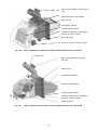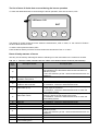
1
HERCULES Green
Hercules
Eco Therm
U26
MANUAL FOR BOILER Návod
OPERATION
k obsluze
AND INSTALATION
Contents:
page
1.
Produced variants of boiler ..........................................................................................................................3
2.
Technical data of the boiler .........................................................................................................................4
3.
Boiler description .........................................................................................................................................6
3.1
Boiler drum construction .....................................................................................................................6
3.2
Control, regulation and safety elements .............................................................................................6
3.2
The construction of burner and transport routes of the fuel................................................................9
4.
Location and installation ............................................................................................................................11
4.1
Regulations and directives ................................................................................................................11
4.2
Positioning possibilities .....................................................................................................................12
5.
Order, delivery and assembly ....................................................................................................................14
5.1
Order .................................................................................................................................................14
5.2
Delivery and accessories ..................................................................................................................14
5.3
Assembly procedure .........................................................................................................................16
5.3.1
Boiler drum installation..................................................................................................................16
5.3.2
Mounting of partitions of the combustion chamber and turbulators ..............................................17
5.3.3
Mounting of burner ........................................................................................................................17
5.3.4
Mounting of the fuel reservoir .......................................................................................................19
5.3.5
Mounting of the shells ...................................................................................................................20
5.3.6
Installation of electrical wiring .......................................................................................................21
5.3.6.1
Version HERCULES Green Eco Therm XJ ..........................................................................21
5.3.6.1
Version HERCULES Green Eco Therm XS..........................................................................22
5.3.7
Assembly tools for brush...............................................................................................................22
5.3.8
Filling of the heat system with water .............................................................................................22
5.3.9
Electrical scheme ..........................................................................................................................23
5.3.10 Boiler hydraulic diagram ...............................................................................................................27
6.
Putting into operation - instructions for contractual service organization ..................................................28
6.1
Inspections before start-up ...............................................................................................................28
6.2
Boiler putting into operation ..............................................................................................................28
7.
Boiler operation by user .............................................................................................................................29
7.1
Version HERCULES Green Eco Therm XJ ......................................................................................29
7.1.1
7.2
Setting of the heat output of burner ..............................................................................................32
Version HERCULES Green Eco Therm XS......................................................................................37
7.2.1
Setting of the heat output of burner ..............................................................................................39
8.
IMPORTANT WARNINGS ........................................................................................................................42
9.
Maintenance ..............................................................................................................................................43
10.
Faults and their removal ........................................................................................................................45
11.
Instructions for product liquidation after its operating life .......................................................................47
12.
Warranty and defect liability ...................................................................................................................47
2
Dear customer,
thank you for the purchase of HERCULES Green Eco Therm boiler; this purchase demonstrates your
confidence in VIADRUS a.s.
In order to get used to a proper treatment of your new product from the start please read these
instructions for its use (first of all the chapter no. 7 – Boiler attendance by user, chapter
no. 11 – Important warnings and chapter no. 12 – Maintenance by user). Please observe the
information given below in order to ensure a longstanding trouble-free operation of boiler so that
both you and we are satisfied.
1.
•
Produced variants of boiler
Order specification code
HERCULES Green Eco Therm X X
Burner output:
Type of burner:
25: 25 kW
32: 32 kW
J: Junior
S: Senior
The fuel tank is included in the standard boiler accessories
•
Optional accessories (see chapter no. 5.2)
The boiler design you received is only destined for wooden pellets combustion (specification see page 6)
and its trade name is HERCULES Green Eco Therm. It is the boiler with automatic fuel supply. The burner is
cleaned manually.
The boiler is manufactured as warm-water boiler with forced heating water circulation and working
overpressure up to 400 kPa (4 bar). The boiler is tested for tightness by applying 800 kPa (8 bar)
overpressure before despatch.
The use:
The version of boiler HERCULES Green Eco Therm 25X is particularly destined for heating of
individual housing units, weekend houses, cottages etc.
The version of boiler HERCULES Green Eco Therm 32X is particularly destined for heating of
cottages, weekend houses, small business premises, smaller leisure amenities etc.
Advantages of boiler:
automatic boiler operation guarantees the heating comfort,
mechanical fuel feed from any reservoir
automatic ignition
simple, not time-consuming attendance and maintenance
high efficiency reaching 87,9 %,
boiler drum construction proven on a long-term basis
high service life of the cast iron boiler drum
five-year guarantee for the boiler drum
3
2.
Technical data of the boiler
Tab. no. 1
Dimensions, thermal parameters of boiler
pcs
HERCULES Green Eco Therm
25X
5
HERCULES Green Eco Therm
32X
7
-
3
3
kg
332
401
kg
l
mm
65
40,9
156
65
50,3
156
mm
1218 x 1309
1218 x 1309
mm
3
dm
kg
3
dm
kg
kPa (bar)
kPa (bar)
-
1335
130
85
725
470
400 (4)
800 (8)
See picture Nr.1
1527
130
85
725
470
400 (4)
800 (8)
See picture Nr.1
°C
60 - 90
60 - 90
°C
60
60
dB
mbar
Doesn´t exceed level 65 dB (A)
0,15 - 0,25
G 1 1/2"
G 1 1/2"
1/N/PE 230 V AC 50 Hz TN-S
100/1200
IP 20
Doesn´t exceed level 65 dB (A)
0,2 - 0,3
G 1 1/2"
G 1 1/2"
1/N/PE 230 V AC 50 Hz TN-S
100/1200
IP 20
Version of boiler
Section number
Class of boiler according to
EN 303-5
Weight including the supplied
fuel tank
Fuel tank weight on demand
Water space volume
Diameter of smoke socket
Boiler dimensions (incl. burner): height x width
- depth
Capacity of the supplied fuel tank
Fuel tank capacity on demand
Water operating overpressure
Testing water overpressure
Hydraulic loss
Recommended heat water
operating temperature
Recommended return water
operating temperature
Noise level
Chimney draught
Boiler connections - heat water
- return water
Connected voltage
Operating electric power/max.
W
Electric protection
Tab. no. 2
Heat - technical parameters of the boiler
Version of boiler
Section number
Nominal output
Minimum output
Efficiency
The approximate fuel
consumption at rated output
The approximate fuel
consumption at minimum output
Burning time at nominal output supplied tank / the tank by
request.
Burning time at minimum output supplied tank / the tank by
request
Heating value
Maximum flue gas temperature
pcs
kW
kW
%
HERCULES Green Eco Therm
25X
5
25
7,5
až 86,8
HERCULES Green Eco Therm
32X
7
32
9,6
až 87,9
kg.h
-1
5,8
8,2
kg.h
-1
1,74
2,45
h
14,17
78,33
10,625
58,75
h
60,7
335,71
35,42
195,83
MJ. kg
°C
-1
17,189
205
17,189
210
Specified fuel:
The pellets must comply at least with one of the standards or regulations as follows:
Direction no. 14-2000 MŽP ČR
DIN 517 31
ÖNORM M 7135
Specified pellets granularity: between 6 and 8 mm
Maximum fuel water content. 12%.
Ash content max. 1,5 %
WARNING!
A poor quality of fuel can markedly negatively affect the boiler output and emission
parameters.
4
300
250
Pa
200
150
100
50
0
15
20
25
30
35
40
45
50
55
60
Power in kW
Fig. no. 1
Version of boiler
L
L1
Hydraulic loss of the boiler drum
HERCULES Green Eco Therm 25X
1335
809
Fig. no. 2
HERCULES Green Eco Therm 32X
1527
1001
Boiler dimensions
5
3.
Boiler description
3.1
Boiler drum construction
The cast iron section boiler drum is the main part of boiler and it is manufactured of grey cast iron according
to EN 1561
•
central sections – quality 150 (previously ČSN 42 2415)
•
front and rear sections – quality 200 (previously ČSN 42 2420)
The pressure parts of boiler conform to the strength requirements according to:
EN 303-5 Boilers for central heating– part 5: Solid fuel boilers for central heating, with a manual or
automatic feed, with nominal thermal output max. 300 kW: terminology, requirements, testing
and marking.
The boiler drum is assembled of sections by means of pressed on boiler insertions and secured by means of
anchor bolts. The sections create the combustion and ash-pan space, the water space and convection part.
The inlet and outlet of heating water are situated in the rear part of boiler.
The rear section of boiler in its upper part has a smoke extension piece and heating water flange, in the lower
part there is the return water flange with a sleeve piece for inlet and outlet cocks. The cleaning door and ash
door with mounted burner are affixed to the front boiler section.
The whole boiler drum is insulated by means of a health harmless mineral insulation which reduces the
losses caused by the heat transfer into ambient. The steel shell colour is treated by means of high-quality
komaxit spray.
3.2
Control, regulation and safety elements
Elements for control, regulation and safety placed in the control cabinet
Thermomanometer serves for measuring the temperature and pressure of water in the heating system and
is located in the upper part of the boiler shell. The check valve for pressure gauge connection is located in the
upper part of the rear boiler section.
Operating thermostat switches off / switches on the operation of the burner according to the set
temperature of heating water.
Signalling of safety thermostat signals the activation of the safety thermostat (overheating of the heating
system above 97 °C)
The safety thermostat is placed in the control box and serves for ensuring the heating system against
overheating. This thermostat is set by the manufacturer to a temperature of 95°C, i.e. to a higher temperature
than can be set as the desired temperature on the boiler. When you turn off the safety thermostat unblocking
must be done manually. The safety thermostat can be turned on only after the temperature has dropped
below the set value. We have to unscrew the black cap of the safety thermostat and by using a suitable
object we press the button.
In case of repeated switching of the thermostat the boiler must be shut down and the reason of repeated
overheating of the boiler must be found out.
The thermostat of the pump switches on and switches off the pump of heating water according to the set
temperature.
1.
2.
3.
4.
Termomanometer
Operating thermostat
The switch "start of burner"
Signalling of safety thermostat
5.
6.
7.
8.
Fig. no. 3
Fuse 10A
Main switch
Safety thermostat
Thermostat of pump
Control box
6
Elements for control, regulation and safety placed on the boiler body
The air rosette of cleaning door and the lower stifling element is not used at the boiler with an automatic
combustion of wooden pellets and must be permanently closed.
Elements for control, regulation and safety placed on the burner
•
Control Module of boiler (version HERCULES Green Eco Therm XJ) or automatic (version
HERCULES Green Eco Therm XS).
•
LCD display with control buttons, that is designed for change of the values of operating parameters
(version HERCULES Green Eco Therm XJ).
•
Potentiometer – for setting the boiler output (version HERCULES Green Eco Therm XS).
•
Photo sensor, which monitors the intensity of the combustion process.
•
Transport hose with reinforcing spiral, which melts in the case of penetration of fuel back through the
knee of burner, thus preventing further supply of pellets into the burner.
•
Sensor of penetration of fuel (TD) is placed on the knee of burner and is activated in case of the
surface temperature above 90 °C. Burner and fuel feeder are stopped in case of activation of this sensor
and the system is switched over into reporting of a failure. The failure mode is deactivated by switching
off and on of the main switch. It is necessary to determine the cause of the failure and take appropriate
measures, namely before restarting of the burner;
•
Reversible thermal label displays the operating temperature of the burner body. This temperature is an
indicator for operating mode of the burner and temperature of flue gases which pass the combustion
chamber back into the fuel tank. The initial state is shown in black colour for all thermally active parts. If
the temperature is increased, the segments gradually are getting a light colour, according to the
temperature range of individual heat-active segments. The reversible thermal label should be checked
as needed. Increased temperature in this section signals the necessity to clean the boiler, grate of
burner or routes of flue gasses and smoke flue. During cooling of the main burner body the colour of the
label returns to its original state (all segments are black).
•
Irreversible thermal label displays overheating of the knee of burner. This label in case exceeding of
temperature of the burner knee irreversibly changes its colour.
The initial status, the active segment is white, the temperature hasn’t
reached the degree of activation 104 °C;
THERMAX
°C
104
°F
219
The status at activation, the active segment is dark, the temperature
has exceeded the degree for activation 104 °C; activation of 104 °C;
THERMAX
°C
104
°F
219
CAUTION:
•
Activation of irreversible thermal label is signalling overheating of the knee of burner. Status of this
label is irreversible and in case of damage it has to be replaced. Control and service of burner may be
performed only by an authorized technician.
•
This thermal label is activated for example when hot combustion products pass back via the fuel feeder
due to an increased resistance of the smoke flue or a lower draft in the chimney. In such cases the
transport hose that connects the fuel feeder and burner body can be damaged and will be necessary its
replacement.
•
In case of these emergency statuses the warranty for the burner is void.
7
1.
2.
3.
4.
5.
6.
7.
8.
9.
10.
11.
12.
Boiler drum
Boiler shell with ashtray
Cleaning door
Burner
Transitionary flange
Insulation of transitionary flange
The ash door
Fuel tank
Fuel feeder
Transport hose with reinforcing spiral
Control box
Flange of heating water
Fig. no. 4
13.
14.
15.
16.
17.
18.
19.
20.
21.
22.
23.
Flange of return water
Fill and drain cock
Sealing 90 x 60 x 3
Assembly of smoke adapter
Turbulators
Partition of flue way
Partition of the combustion chamber- the
front section
Partition of the combustion chamber
Hose clamp
Screw M10 x 50
Screw M10 x 30
Boiler assembly
8
3.2
The construction of burner and transport routes of the fuel
The version HERCULES Green Eco Therm XJ
• Control module with microprocessor;
• LCD display with control buttons, that is designed for change of the values of operating parameters;
Version HERCULES Green Eco Therm XS
• Control panel on which there is placed a potentiometer for setting the boiler output;
• Colour scale on which we can set the position of throttle flap of the fan (the output power of fan) to the
same colour as the setting of the thermal output potentiometer.
•
Manual setting of throttle flap of the fan.
Version of boiler
Nominal heat output
power range
HERCULES Green Eco Therm
25S
32J
25
32
7,5 - 25
9,6 - 32
25J
25
7,5 - 25
32S
32
9,6 - 32
The burner consists of following components:
•
Combustion chamber, which serves for burning pellets and made from high quality stainless steel;
•
Removable grate of combustion chamber;
•
Electric spiral, by means of which the fuel is ignited. It is located behind the inclined plate of grate in the
combustion chamber;
•
Fan for intake of air, equipped with Hall effect sensor for sensing the rotational speed;
•
Photo sensor, which monitors the intensity of the combustion process;
•
Sensor for penetration of burning fuel (TD) which stops the operation of the burner in case of break
forth of flame into the fuel feeder;
•
Socket for connecting the fuel feeder, which ensures power supply into the motor of the fuel feeder;
•
Reversible thermal label from a liquid crystal with the indicator of current temperature of the
body of burner.
•
Irreversible thermal label from a liquid crystal which signals the high temperature of the knee of
burner, preliminarily sets the conditions for the non-warranty service of the main module of burner and of
any kind of damage to the hose for fuel supply;
•
Fuel feeder with an inlet cable and 1 ~ plug.
•
Transport hose with reinforcing spiral, which is made partly of a transparent heat-resistant material
(in case of burning does not emit toxic substances and does not maintain the process of burning), that
interconnects the fuel feeder and the knee of burner;
Fuel feeder
Transport hose
with reinforcing
spiral
Knee of
the burner
Burner
Fig. no. 5
Burner and fuel feeder
9
Sensor for penetration of burning fuel
(TD)
LCD display with control buttons
Photo sensor
Combustion chamber
Control module of boiler
Transitionary flange for mounting the
burner to the door of boiler
Inlet of electricity
Socket for connection of the fuel feeder
Fig. no. 6
Basic components of the burner of boiler HERCULES Green Eco Therm XJ
Control panel
Sensor for penetration of burning
fuel (TD)
Photo sensor
Combustion chamber
Control module of boiler
Throttling flap of the fan
Transitionary flange for mounting the
burner to the door of boiler
Inlet of electricity
Fig. no. 7
Basic components of the burner of boiler HERCULES Green Eco Therm XS
10
Irreversible thermal
label
Reversible thermal
label with indicator of
current temperature
of the body of burner
Fig. no. 8
Positioning of thermal labels on the burner
4.
Location and installation
4.1
Regulations and directives
The solid fuel boiler can only by mounted by a company holding a valid authorization to install these
equipments.
A project according to the valid regulations must be prepared for the installation.
The heating system must be filled with water that matches the requirements of ČSN 07 7401 and
especially its hardness must not exceed the required parameters.
Recommended values
Hardness
mmol/l
2+
Ca
mmol/l
Concentration of total Fe + Mn
mg/l
1
0,3
(0,3)*
*) Recommended value
WARNING!!! The use of anti-freeze mixture is not recommended by the manufacturer.
a) regarding the heating system
ČSN 06 0310
Thermal systems in buildings – Design and installation
ČSN 06 0830
Thermal systems in buildings – Protecting devices
ČSN 07 7401
Water and steam for thermal energetic devices with steam working pressure up
to 8 MPa.
EN 303-5
Boilers for central heating – Part 5: Solid fuel boilers for central heating with
manual or automatic feed and max. 300 kW nominal thermal output:
terminology, requirements, testing and marking.
b) regarding the chimney
ČSN 73 4201
Chimneys and flue gas ducting– designing, implementation and connection of
fuel consumers.
We recommend that HERCULES Green Eco Therm boiler is connected to the smoke flue with min.
160 mm diameter and the chimney draught must be 0,15 - 0,3 mbar – see Tab. no. 1.
c) regarding the fire regulations
ČSN 06 1008
Fire safety of thermal equipments
EN 13 501-1 + A1
Fire classification of construction products and building elements – Part 1:
Classification using test data from reaction to fire tests.
d) regarding the electric network
ČSN 33 0165
Electrical regulations; marking the leading wires by colours or digits;
implementing regulations
ČSN 33 1500
Electrical regulations; revision of electrical equipments
ČSN 33 2000-3
Electrical regulations; electrical equipments Part 3: Setting the basic
characteristics.
11
ČSN 33 2000-4-41
ČSN 33 2000-5-51 ed. 2
ČSN 33 2130
ČSN 33 2180
ČSN 34 0350
EN 60 079-10
EN 60 252-1
EN 60 335-1 ed.2
EN 60 335-2-102
EN 60 445 ed. 3
EN 60 446
Electrical equipments: part 4: Safety chap. 41: Protection against electric shock
Electrical regulations: Electrical equipments construction
Electrical regulations: Internal electricity distribution
Electrical regulations: Connection of electric instruments and appliances
Electrical regulations: Regulations for flexible cords and cord lines
Electrical regulations: Regulations for electrical equipments at the places with
explosion hazard with flammable gases and vapours.
Capacitors for AC motors – Part 1: In general – Design, testing, dimensioning –
Safety requirements – Instructions for installation and operation.
Electric appliances for household and similar purposes – Safety – Part 1:
General requirements
Electric appliances for household and similar purposes – Safety – Part 2-102:
Special demands on appliances containing the electric connections and burning
the gas, oil and solid fuels
Basic and safety principles for man – machine interface, marking
and identification
Basic and safety principles of machinery operation - Marking the leading wires
with colours or digits
e) regarding the system for HWS heating
ČSN 06 0320
Thermal systems in buildings– Hot water preparation– Design and project
engineering
ČSN 06 0830
Thermal systems in buildings – Protecting devices
ČSN 73 6660
Internal water piping
4.2
Positioning possibilities
The boiler is approved for installation in non – residential spaces (for example – cellar, corridor, etc.)
The installation of the boiler must comply with all requirements of ČSN 06 1008.
ATTENTION!
In the event that it is installed the delivered wooden fuel reservoir, then it is necessary to install a
fireproof bulkhead between the reservoir and boiler.
Boiler placing with regard to fire regulations:
1. Placing on floor of flame resistant material (Fig. no. 9)
- boiler to be put on a flame resistant backing exceeding the boiler platform over 20 mm at sides and
only on the boiler drum depth.
- if the boiler is situated in a cellar we recommend to place it on a bedding of minimum 50 mm height.
5
680
Section number
L [mm]
Fig. no. 9
7
872
Bedding dimensions
12
2. A safe distance from the combustible materials:
- when installing and operating the boiler it is necessary to keep a safety distance of 200 mm from the
materials of combustibility grade A1, A2, B and C (D);
- for easily combustible materials of combustibility grade E (F), which quickly burn and burn
themselves even after removal of ignition source (such as paper, cardboard, asphalt and tar paper,
wood and wood-fiber boards, plastics, floor coverings) the safe distance has to be doubled, i.e. to
400 mm;
- safe distance should be doubled as bulb where the grade of reaction to fire has not been proved.
Tab. no. 3
Grade of reaction to fire
Examples of building materials and products included in the reaction to fire
(Extract from EN 13 501-1 + A1)
Granite, sandstone, concrete, bricpcs, ceramic tiles, mortars, fireproof plasters, …
A1 – incombustible
A2 – combustible with difficulty acumin, izumin, heraklit, lignos, boards and basalt felt, fibreglass boards,...
Beech and oak wood, hobrex boards, plywood, werzalit, umakart, sirkolit,...
B – hardly combustible
Pinewood, larch, whitewood, chipboard and cork boards, rubber flooring,...
C (D) – medium combustible
Asphaltboard, fibreboards, cellulose materials, polyurethane, polystyrene,
E (F) – easily combustible
polyethylene, PVC,…
Grade of reaction to fire
The boiler placing with respect to the necessary handling space:
•
basic surroundings of AA5/AB5 according to ČSN 33 2000-3
•
handling space of minimum 1000 mm in front of the boiler must be maintained
•
a minimum distance of 400 mm between the back part of the boiler and the wall
•
from the side of the boiler there must be maintained a space at least 500 mm for the door opening and
for the access to the rear part of the boiler;
•
a minimum distance of 100 mm from the side wall.
Fig. no. 10 Boiler placing in a boiler room
Fuel placing:
•
•
dry fuel (up to the 12% moisture) must be used in order to guarantee the correct combustion in the
boiler. The pellets should be stored in their original packing from the manufacturer
(e.g. PET sacpcs) at a dry place;
it is impossible to store fuel behind the boiler or unload it next to the boiler in a distance smaller than
400 mm;
13
•
the manufacturer recommends that min. 1000 distance is kept between the boiler and fuel or the fuel is
placed in a room different from that where the boiler is installed
Boiler positioning with regard to electricity network:
•
•
•
the boiler must be placed so that the plug in socket (230V/50Hz) is always accessible;
the boiler is connected to the mains by a fixed movable inlet with a normalized plug;
the electric shock prevention must be guaranteed according to valid EN (see chap. 5.1.)
A permanent air supply for combustion and ventilation must be guaranteed in the room where
the boiler is installed (the air consumption of HERCULES Green Eco Therm 5X boiler amounts to
3 -1
approx. 80 m .h , the air consumption of HERCULES Green Eco Therm 7X boiler amounts to approx.
3 -1
160 m .h .
The connection of heating system piping must be carried out by a person authorised according to
the valid regulations.
.
CAUTION:
When connecting the boiler to the heating system there must be installed a inlet and
outlet cocpcs in the lowest point and as near as possible to the boiler (at the return
water flange).
5.
Order, delivery and assembly
5.1
Order
In the order the following is needed to be specified:
1.
2.
5.2
Output and type of burner (see chap. 1)
Requirements for accessories offered on request
Delivery and accessories
Boiler HERCULES Green Eco Therm is supplied so that on a pallet there is placed the complete boiler drum
and on the side there is attached the wrapped boiler shell. The accessories are stored inside the boiler drum
and are accessible after opening the cleaning door. On the other pallet there is stored wooden fuel container,
in which there is stored the burner, the fuel feeder and their accessories. The boiler is packed into a shipping
container and must not be flipped during shipping; it is only permitted to tilt to the sides in order to remove the
wrapping from the boiler drum.
Standard accessories to boiler:
•
•
•
•
•
•
•
Boiler with the appropriate number of boiler sections on the palette
Flange of heating water G 1 1/2"
Return water flange G 1 1/2 "with socket Js 1/2" for the fill and drain cock
•
Sealing φ 90 x 60 x 3
•
Washer 10,5
•
Nut M10
•
The fill and drain cock Js 1/2“
•
Three-position sump of thermostat G 1/2"
•
spring of the capillary
•
Blind plug Js 6/4“
•
Sealing 60 x 48 x 2
Fasteners for mounting of a transitionary flange
screw M10 x 50
screw M10 x 30
spring washer 10
washer 10,5
nut M10
Insulation of the transitionary flange
The boiler shell including the ashtray and insulation in the adequate size
Fasteners for jacketing
console 1 assembly
console 2 assembly
washer 10,5
nut M10
connecting pin
screw M5 x 12
14
1 pc
1 pc
2 pcs
8 pcs
8 pcs
1 pc
1 pc
1 pc
1 pc
1 pc
1 pc
3 pcs
4 pcs
4 pcs
4 pcs
2 pcs
2 pcs
4 pcs
4 pcs
4 pcs
4 pcs
washer 5,3
screw into the plate ST 4,2 x 9,5
spring clamp
bushing PG 9
control box
screw M5 x 12
serrated washer 5,3
cleaning equipment
hook
brush with handle
pike
cleaning equipment holder
handling key
turbulator
partition of combustion chamber – the front segment
the partition of combustion chamber
the partition of smoke channel
burner
fasteners for mounting of burner
screw M10 x 50
screw M10 x 30
spring washer 10
washer 10,5
nut M10
insulation of burner
transitionary flange of the burner
fuel feeder
transport hose with reinforcing spiral
hose clamp
fuel reservoir
sloping bottom
flange of the fuel feeder
fasteners for the fuel reservoir
screw M8
nut M8
washer 8,4
flexo cord 5 m
boiler label
business – technical documentation
-
•
•
•
•
•
•
•
•
•
•
•
•
•
•
•
•
4 pcs
6 pcs
4 pcs
7 pcs
1 pc
4 pcs
4 pcs
1 pc
1 pc
1 pc
1 pcs
1 pc
4 pcs
1 pc
4 pcs - 7 sect.
2 pcs
1 pc
3 pcs
3 pcs
6 pcs
6 pcs
6 pcs
1 pc
1 pc
1 pc
1 pc
2 pcs
1 pc
2 pcs
1 pc
10 pcs
10 pcs
10 pcs
1 pc
1 pc
Accessories delivered by request:
•
•
fuel reservoir 725 l
- the side of fuel reservoir
- the side of fuel reservoir with the hole for spiral worm
- the foot of fuel reservoir
- the bottom of fuel reservoir
- the bottom of fuel reservoir A
- the cover of fuel reservoir
- handle
connection accessories for fuel reservoir assembly
- pendant chainlet
- screw M6 x 12
- washer 6,4
- nut M6
- screw M6 x 16
- washer 8,4
The boiler equipment delivered “by request“ is not included in the basic price of boiler
15
3 pcs
1 pc
4 pcs
2 pcs
2 pcs
1 pc
1 pc
1 pcs
72 pcs
72 pcs
72 pcs
2 pcs
2 pcs
5.3
Assembly procedure
5.3.1 Boiler drum installation
1.
2.
3.
4.
5.
1
2
Position the boiler body on a retaining wall.
Put sealing 90 x 60 x 3 (1) onto the upper flange of the rear boiler section and screw the flange of
heating water (2) and then interconnect the other end with the heating system.
Put sealing 90 x 60 x 3 (5) onto the lower flange of the rear boiler section and screw the flange of
heating water with a sleeve (6) for the fill and drain cock and then interconnect the other end with the
heating system.
After connecting the boiler to the heating system screw a knee with the fill and drain valve (9) into the
sleeve of the flange of return water.
Then screw the sump of thermostat G 1/2 "into the hole in the upper part of the rear boiler section
(Fig. no. 11).
Check valve for
the manometer
Boiler basin
Fig. no. 11
6.
7.
1.
2.
3.
4.
5.
6.
7.
8.
9.
Then carry out blinding of the threaded hole Js 6/4 "in the front boiler section by using a blinding plug Js
6/4". Place the seal 60 x 48 x 2 under the blinding plug.
Fit the smoke pipe onto the smoke adapter and insert it into the chimney opening.
Sealing φ 90 x 60 x 3
Heating water flange
Washer10,5
Nut M10
Sealing φ 90 x 60 x 3
Return water flange
Washer 10,5
Nut M10
Filling and draining cock
Fig. no. 12 Boiler drum installation
16
5.3.2 Mounting of partitions of the combustion chamber and turbulators
1.
2.
3.
1.According to Fig no. 13 insert the partitions of the combustion chamber (1, 2) into the combustion
chamber in number of 4 pcs (for HERCULES Green Eco Therm 5X) or 5 pcs (for HERCULES Green
Eco Therm 7X).
Insert 2 pcs partitions of the smoke channel (3) between the front and middle boiler section.
3.Put 4 pcs turbulators (4) into the route of flue gases
1.
2.
3.
4.
Partition of the combustion chamber– the front section
Partition of the combustion chamber
Partition of the smoke channel
Turbulator
Fig. no. 13
Positioning of the partitions of combustion chamber in boiler
5.3.3 Mounting of burner
567 mm for HERCULES Green Eco Therm 5X
630 mm for HERCULES Green Eco Therm 7X
Fig. no. 14
Dimensions of burner
17
1.
2.
3.
4.
Please screw the flange of burner (see Fig. no. 15) onto the ash door by means of 3 pcs screws
M10 x 30 (2), 1 pc screw M10 x 50 (2), 4 pcs nuts M10, 4 pcs washers 10,5 and 4 pcs spring washers
10,5.
Screw the knee of the burner on the body of burner with the throat directed onto the positioning of the
fuel reservoir.
Mount the burner insulation onto the flange of the burner.
Screw the burner with insulation to the transitionary flange by means of 2 pcs screws M10 x 50, 2 pcs
nuts M10, 2 pcs washers 10,5 and 2 pcs spring washers 10,5.
1.
2.
Screw M10 x 50
Screw M10 x 30
Ash door
Transitionary flange for
installation of burner
Fig. no. 15
The lower door with the flange of burner
18
5.3.4 Mounting of the fuel reservoir
ATTENTION!
In the event that it is installed the supplied wooden fuel reservoir, it is necessary to place a fireproof
bulkhead between it and the boiler.
•
•
•
•
•
According to Fig no. 16 you must screw the flange of fuel feeder (3) to the lateral part of the fuel
reservoir (6) by using 6 pcs screw M8 x 20 (5), M8 nuts (2) and washers 8.4 (4);
Then you must screw together inclined bottom (7) by means of 4 pcs screw M8 x 30 (8), M8 nuts (2) and
washers 8.4 (4);
Put the assembled inclined bottom (7) into the fuel tank;
Insert the fuel feeder (1) into the flange of fuel feeder (3).
The fuel feeder should form an angle of 45 degrees with the horizontal floor in order to ensure optimal
operating conditions. The lower part of the feeder should be placed at the lowest point of fuel reservoir.
The fuel feeder and reservoir must be placed so that there is ensured a safe operation of equipment and
an easy access and maintenance.
ATTENTION: Any change in the angle of the fuel feeder affects the amount of the dosed fuel:
• reduction of the angle will lead to an increased dosing of fuel;
• Increase of the angle will lead to a reduced dosing of fuel;
•
•
Then position the fuel tank with the fuel feeder in the proximity of the burner so as to prevent clogging of
the transport hose with the pellets during supply of fuel and also to make it possible to open the cleaning
door and ash door.
After mounting of the shells (see chap. 5.3.5) interconnect the transport hose with the knee of burner
and secure by means of hose clamps. ps.
The assembled
bottom
Fig. no. 16
1
2
3
4
5
6
7
8
Fuel feeder
Nut M8
Flange of fuel feeder
Washer 8,4
Screw M8x20
Fuel reservoir
Inclined bottom
Screw M8x30
The fuel feeder with the supplied fuel reservoir
19
1 pc
10 pcs
1 pc
14 pcs
6 pcs
1 pc
2 pcs
4 pcs
5.3.5 Mounting of the shells
1
2
3
4
5
6
7
8
9
10
Anchor screw
Console 1
Washer 10,5
Nut M10
Console 2
Right side part of shell
Insulation of the side part of shell
Connecting pin
Washer 6,4
Screw M5 x 12
11
12
13
14
15
16
17
18
19
20
Right side part of shell
Screw ST 4,2 x 9,5
Insulation of the rear part of shell
Rear part of shell
Upper part of shell
Insulation of the upper part of shell
Spring clamp
Control box
Washer 5,3
Cable gland PG 9
Fig. no. 17 Mounting of jacketing
1.
2.
3.
Remove shells out of the carton wrapping.
Fitting is carried out according to Fig no. 17th
Put the consoles (1) (2) and 2 (5) on the threads of the upper anchor screw (1) (2) and 2 (5) and screw
them by using 2 pcs M10 nuts (4) and 2 pcs 10.5 washers (3)
20
4.
You will mount the connecting pins 2 pcs (8) on the right side part of the shell (6) and then insert the
insulation (7). Then you will install the jacket (shell) (6) on lower anchor screws and connect the upper
part with consoles 1 and 2 by using 2 pcs M5 x12 screw (10) and 2 pcs 5.3 washers (9).
5. Put the consoles 1 (2) and 2 (5) on the threads of the left upper anchor screw and screw them by using
the 2 pcs M10 nuts (4) and 2 pcs 10.5 washers (3).
6. You will mount the connecting pins 2 pcs (8) on the left side part of the shell (11) and then insert the
insulation (7). Then you will install the jacket (shell) (6) on lower anchor screws and connect the upper
part with consoles 1 and 2 by using 2 pcs M5 x12 screw (10) and 2 pcs 5.3 washers (9).
7. Then you will mount the insulation of the rear part of the shell (13) on the rear part of the shell (14) and
screw it to the side parts of the shell by using 6 pcs screw ST 4,2 x 9,5 (12).
8. Put the insulation of the upper part of the shell (16) on the boiler drum.
9. Mount spring clamps 4 pcs (17) on the upper part of the shell (15).
10. The next assembly process of the control box and wiring see chap. Section 5.3.6.
5.3.6 Installation of electrical wiring
5.3.6.1 Version HERCULES Green Eco Therm XJ
1.
2.
3.
4.
5.
6.
7.
8.
9.
10.
11.
12.
13.
According to Fig no. 17 equip the upper part of the shell (15) with the glands PG 9 (20)
Attach the control box (18) to the upper part of the shell (15) by using of screws M5 x 12 (10) and
serrated lock washers 5.3 (19) and pull the capillary tube of safety thermostat, capillary tubes of
thermomanometer and the capillary tube of the thermostat of pump through the hole.
Pull the supply cable of burner WL4 through the gland PG 9 (located in front part of the upper section of
the shell) and connect the cable wires to the control box to the terminals:
black
terminal X1: 5
brown
terminal X1: 10
grey (blue)
terminal X1: 11
yellow-green
terminal X1: 12
Unscrew the cover of burner and pull the cable of burner control WL2 through a rubber grommet and
connect the cable to the terminals
black
A1: K22
grey
A1: K23
blue
A1: K10
brown
A1: K11
Secure the cable of burner control WL2 against pulling out by using a tightening tape.
Pull the other end of the cable of burner control WL2 through the gland PG 9 (located in front part of the
upper section of the shell) and connect the cable wires to the control box to the terminals:
black
terminal X1: 6
grey
terminal X1: 9
brown
terminal X1: 16
blue
terminal X1: 17
Pull the sensor of heating water B1 through the gland PG 9 ( located in front part of the upper section of
the shell).
Connect the supply flexo-cord to the control box to the terminals:
brown
X1: L
blue
X1: N
yellow-green
X1: PE
Connect the pump and room thermostat according to the electrical scheme, see chap. No. 5.3.9.
Insert B1 sensor of heating water, capillary tube of safety thermostat, capillary tubes of
thermomanometer and the capillary tube of thermostat of pump into the sump of boiler (see Fig no. 12)
and secure with a spring.
Screw the capillary tube for pressure of manometer into the reverse valve for pressure gauge in the rear
section of boiler drum (see Fig no. 12)
Fit the upper part of the shell on the boiler and screw the upper part of the control box.
Insert 1 ~ plug of the fuel feeder into the socket of burner.
WARNING:
Version HERCULES Green Eco Therm XJ is equipped with sensor B1 of hot water.
For this reason the operating thermostat in the control box is shunted to terminals
X1: 7 and X1: 8 and does not serve for control of the operation of burner.
21
5.3.6.1 Version HERCULES Green Eco Therm XS
1.
2.
3.
4.
5.
6.
7.
8.
9.
According to Fig no. 17 equip the upper part of the shell (15) with the glands PG 9 (20)
Attach the control box (18) to the upper part of the shell (15) by using of screws M5 x 12 (10) and
serrated lock washers 5.3 (19) and pull the capillary tube of safety thermostat, capillary tubes of
thermomanometer and the capillary tube of the thermostat of pump through the hole..
Pull the supply cable of burner WL4 through the gland PG 9 (located in front part of the upper section of
the shell) and connect the cable wires to the control box to the terminals:
black
terminal X1: 5
brown
terminal X1: 10
grey (blue)
terminal X1: 11
yellow-green
terminal X1: 12
Connect the supply flexo-cord to the control box to the terminals::
brown
X1:L
blue
X1:N
yellow-green
X1:PE
Connect the pump and room thermostat according to the electrical scheme see chap. No. 5.3.9.
Insert the capillary tube of safety thermostat, capillary tubes of thermomanometer and the capillary tube
of thermostat of pump into the sump of boiler (see Fig no. 12) and secure with a spring.
Screw the capillary tube for pressure of manometer into the reverse valve for pressure gauge in the rear
section of boiler drum (see Fig no. 12)
Fit the upper part of the shell on the boiler and screw the upper part of the control box.
Insert 1 ~ plug of the fuel feeder into the socket of burner.
5.3.7 Assembly tools for brush
Use the leather gloves and common assembly tools for mounting or dismounting of the brush and the spike
point (if they are included in the delivery).
5.3.8 Filling of the heat system with water
Water for filling of the boiler and the heat system must be pure and colourless, without suspended
substances, oil and chemically aggressive substances. Its hardness must correspond to ČSN 07 7401 and in
case it does not correspond it is necessary the water to be adjusted. Even multiplying heating of the water
with higher hardness does not prevent from excluding of soils on the boiler drum walls. The precipitation of
1 mm of limestone reduces in the given place the heat transfer from metal to water by 10 %.
Heat systems with an open expansive tank allow direct contact of the heat water with atmosphere. In the heat
period the expansive water in the tank absorbs oxygen that increases the rust effects and at the same time a
considerable vaporization of water occurs. Only water adjusted to values according to ČSN 07 7401 can be
used for fill – up. The heat system is needed to be rinsed so as all impurities have been washed out.
During heat period it is necessary to keep consistent water volume in the heat system. While filling – up of the
heat system with water it is necessary to prevent the air from leeching onto the system. The water from boiler
and heat system must never be impregnated or taken out for use except for cases necessarily needed such
as repairs, etc. By draining the water and filling with new one the risk of rust and scale creation is increased.
If it is needed to fill water into the heat system we fill it only to a cooled down boiler to prevent
section cracking. After filling of the boiler and heat system checking of tightness of all joints is needed.
The finishing of assembly and the heat test performance must be recorded in the warranty card.
22
23
Fig. no. 18a) Circuit diagram of HERCULES Green Eco Therm XJ
Q1
BT3
F1
Z1
S1
H1
MAIN SWITCH
SIGNALLING
„SWITCHED ON“
FUSE 10 A
SUPPRESSOR
FILTER X31.1 10 A
THERMOSTAT OF
PUMP
CENTRAL HEATING
PUMP
S2
A6
A1
R1
BT1
H2
SAFETY THERMOSTAT
SIGNALLING OF SAFETY
THERMOSTAT
SWITCH „START OF BURNER“
ROOM THERMOSTAT
AUTOMATICS OF BURNER
KINDLER OF BURNER
M1
B1
M2
TD
PhS
M3
FAN OF BURNER
NTC SENSOR OF HEATING WATER
MOTOR OF BURNER FEEDER
SENSOR OF PENETRATION OF BURNED FUEL
PHOTOSENSOR OF BURNER
FAN OF FLUE GASES ( OPTIONAL)
*- operational thermostat is put out of its function
5.3.9 Electrical scheme
Central heating pump
(HO5VV - F 3Cx0,5)
Supply cable of
burner
(HOSRR - F 4G1)
Room thermostat
(HO5VV - F 2Dx0,5)
Supply flexo-cord
HO5VV - F 3Cx0,75
BN (A1:K11)
BN
BK (A1:K22)
GNYE
In case of a bad draw-off
of the flue gases
Flue gases fan
(HO5VV - F3Gx0,5)
BU
Box
BU (A1:K10)
Box cover
GNYE
BU
GNYE (A1:PE)
BN
GR * (A1:K1)
GR (A1:K23)
BN (A1:K3)
Control of burner
(HO5VV - F 5Cx0,5)
BK (A1:K2)
GNYE
BU
BN
Fig. no. 18b) Circuit diagram of HERCULES Green Eco Therm XJ
24
MAIN SWITCH
SIGNALLING „SWITCHED ON“
FUSE 10A
SUPPRESSOR FILTER X31.1 10A
TERMINAL BLOCK
SAFETY THERMOSTAT
SIGNALLING OF SAFETY
THERMOSTAT
SWITCH „START OF BURNER“
OPERATIONAL THERMOSTAT
THERMOSTAT OF PUMP
Wire colour
GNYE
green yellow
BK
black
BN
brown
BU
blue
GR
grey
* - In WL4 cable is alternatively a grey or
blue conductor
S2
BT2
BT3
S1
H1
F1
Z1
X1
BT1
H2
Fig. no. 19a) Circuit diagram of HERCULES Green Eco Therm XS
25
Q1
BT3
F1
Z1
S1
H1
MAIN SWITCH
SIGNALLING
„SWITCHED ON“
FUSE 10 A
SUPPRESSOR
FILTER X31.1 10 A
THERMOSTAT OF
PUMP
CENTRAL HEATING
PUMP
S2
BT2
A6
A1
BT1
H2
SAFETY THERMOSTAT
SIGNALLING OF SAFETY
THERMOSTAT
SWITCH „START OF BURNER“
OPERATIONAL THERMOSTAT
ROOM THERMOSTAT
AUTOMATICS OF BURNER
R1
M1
M2
P
TD
PhS
KINDLER OF BURNER
FAN OF BURNER
MOTOR OF BURNER FEEDER
POTENTIOMETER OF BURNER OUTPUT
SENSOR OF PENETRATION OF BURNED FUEL
PHOTOSENSOR OF BURNER
FEEDING
Box cover
Central heating pump
(HO5VV - F 3Cx0,5)
Supply cable of
burner
(HOSRR - F 4G1)
Supply flexo-cord
HO5VV - F 3Cx0,75
Box
GNYE
BU
GNYE (A1:PE)
BN
GR * (A1:K1)
BN (A1:K3)
Room thermostat
(HO5VV - F 2Dx0,5)
BK (A1:K2)
GNYE
BU
BN
Fig. no. 19b) Circuit diagram of HERCULES Green Eco Therm XS
26
MAIN SWITCH
SIGNALLING „SWITCHED ON“
FUSE 10A
SUPPRESSOR FILTER X31.1 10A
TERMINAL BLOCK
SAFETY THERMOSTAT
SIGNALLING OF SAFETY
THERMOSTAT
SWITCH „START OF BURNER“
OPERATIONAL THERMOSTAT
THERMOSTAT OF PUMP
Wire colour
GNYE
green yellow
BK
black
BN
brown
BU
blue
GR
grey
*- in the cable WL4 alternatively a grey or
blue conductor
S2
BT2
BT3
S1
H1
F1
Z1
X1
BT1
H2
5.3.10 Boiler hydraulic diagram
Fig. no. 20
Fig. no. 21
HERCULES Green Eco Therm boiler hydraulic diagram
HERCULES Green Eco Therm boiler hydraulic diagram with HWS reservoir and Danfoss
valve
Legend:
1. Boiler
2. Heating system
3. Thermostatic valve
4. Pump
5.
6.
7.
8.
27
Safety valve
Expansion tank
HWS reservoir
Danfoss FJVR valve
6.
Putting into operation - instructions for contractual service
organization
The boiler can only be put into operation by a contractual service organization authorized to carry out
this activity.
6.1
Inspections before start-up
Before putting the boiler into operation it I necessary to check:
1.
2.
3.
4.
6.2
Filling the heat system with water (thermomanometer check).
Tightness of heating system.
Connection to the chimney – it must be approved by a chimney-sweepers’ company.
Connection to the electricity network - it must be approved by an authorized company.
When connecting the sockets the grounding pin must be upward and the phase conductor is connected
to the left female connector in front view. The same applies to the double receptacles.
Boiler putting into operation
1.
Fire the boiler (see chap. 7.). When firing up the protective spraying of boiler section is baked and this
process is accompanied by a slight smell. Mind the boiler room ventilation.
2.
Bring boiler to the necessary service temperature. The recommended heating water temperature is
between 60 and 90 °C.
3.
Check whether the set parameters of burner correspond to the required power of a given heating
system. Setting the operating parameters (see chap. 7.1.1 and 7.2.1)
4.
Carry out the heating test according to relevant standards (see the Guarantee certificate).
5.
Recheck visually the boiler tightness.
6.
Make the user acquainted with boiler attendance (see chap. 7).
7.
Make a registration in the Guarantee certificate.
28
7.
Boiler operation by user
Before putting the boiler into operation or in case that the fuel feeder is empty during operation and it is
necessary to fill the fuel feeder with pellets:
•
pull out the plug 230 V from the socket of burner;
•
insert the plug of power supply (230 V/50 Hz);
•
wait until the wooden pellets start to discharge from the throat of the fuel feeder;
•
pull out the plug from the power supply and insert it back into the socket of burner.
7.1
Version HERCULES Green Eco Therm XJ
Home screen
S
button to enter a submenu or to confirm the setting
+ And - buttons for movement in menu and modifying of values
ESC key for return to the higher level of menu or return to the main menu
Software version number
of control module of
burner
GREEN ecoTHERM
v2s 1
S
-
+
ESC
Activate?
ENTER
S
-
+
For putting the burner into operation press the button "S"
•
Activate? (activate)
putting the burner into operation
29
ESC
After putting the burner into operation the following message appears on the display:
TEST – BLOWING
ON 32
o
S
FC: 0%
-
+
ESC
The display shows information about the current operating mode of the burner:
•
•
•
TEST - BLOWING (blowing through the burner) the burner performs the initial blowing through with
the purpose to remove all debris from the grate of burner;
32°
actual water temperature in the boiler. The water temperature in the boiler is displayed in
case the burner is started in the mode of sensing the water temperature by means of a sensor;
FC: 0%
intensity of flame, measured by means of a photosensor (%)
The display shows information about the operating mode of the burner - the burner is in the mode of
ignition of fuel:
IGNITION 1 150
ON 32o
S
FC: 0%
-
+
ESC
After removal of debris by means of a fan the fuel feeder starts to supply the initial quantity of fuel and the
burner performs the ignition of fuel. The display shows the operating mode "IGNITION 1" (ignition) - this is the
first attempt (denoted as 1) of ignition of fuel which lasts for a period that can be set in the service software;
30
After a successful ignition of fuel the operation of burner will continue to operate according to the factory
setting in order to stabilize the combustion process according to the data on the display - see the Figure
below:
TRANS.: 10kW
ON 32o
-
S
TRANS.:10kW
FC: 65%
+
ESC
the burner is in the mean operating mode and it works with a heat output of 10 kW;
The burner from the mode of stabilization passes into automatic mode. The performance will change
depending on the desired temperature of outlet water from the boiler.
COMBUST 5 32kW
ON 72
S
•
COMBUST 5 – 32kW
•
•
72
FC: 98%
°
o
FC: 98%
-
+
ESC
the degree of operating heat output of the burner (in the event that the
burner works in the degree 5 of heat output and its power is 32 kW);
temperature of outlet water from the boiler, [°C];
intensity of flame measured by means of a photosensor [%];
31
Items of user menu of control module of burner
The user menu starts up on the display by a long pressing the button "S".
By pressing the button "S" you go to the selection of menu of control module of burner.
To exit the current item of menu press "ESC".
COMBUST 5 32kW
ON 75
o
S
FC: 98%
-
+
ESC
7.1.1 Setting of the heat output of burner
You can set the heat output of burner through the selection of the degree of heat output (EFFECT LEVEL).
EFFECT LEVEL
ENTER
S
EXIT
-
+
ESC
Heat output of burner [kW]
Degree of heat output (EFFECT LEVEL)
1
2
3
4
5
25J
32J
7.0
15.0
20.0
25.0
28.0
10.0
20.0
25.0
32.0
32.0
We recommend that you use the burner up to the degree 4 of its heat output. The degree 5 is
intended for operation only at high heat consumption during a short period of time.
To select "Effect level" press "S". Use the + and - buttons to select the degree of heat output according to
the required output of burner. To confirm your choice, press "S".
To return to a higher level menu or return to the main menu, press "ESC".
32
Effect level
[n]
O:5
S
N:5
-
+
ESC
ATTENTION: In case that the fuel has changed (for instance the class of pellets has changed), then an
additional adjustment of operating parameters of the burner should be done.
NOTE:
The burner in case of a change of the degree of heat output automatically re-adjusts the fan
power and the quantity of fuel;
Stopping of the operating mode of the burner by switching off the button „START OF
BURNER“
Use "START OF BURNER" button for switching on and the operation of the burner and the subsequent
switching off and stopping of burner. The display of control module after switching off the burner shows the
message: „FINAL COMBUSTION“ (the final combustion).
ATTENTION: To turn off the burner, use the "START OF BURNER". Do not turn off power supply of burner.
The reason for this measure is that the button "START BURNER" activates the controlled process of
switching off of the control module of burner, which also cools the unit and ensures that all carbonaceous
residues are burnt, and thus retains the reliability and performance of the burner.
Stopping of the operating mode of burner by setting the item in menu of its control module.
To stop the burner operation is necessary to proceed as follows:
• Press and hold the "ESC" (longer than 5 seconds);
• Give an answer to the question "Make final comb.?" (should be carried out the final combustion?) that
appears on the display of control module by selecting "YES" (yes);
If you select "YES" (yes), the display shows "MAN FINAL COMB" (final combustion) and the control module
will shut down the burner.
Other way to stop the operation of the burner, see below:
To stop the burner operation it is necessary to enter into the item "MAKE FINAL COMB." (Carry out the final
combustion) in the menu of control module of burner.
MAKE FINAL COMB.
ENTER
S
EXIT
-
+
ESC
To confirm your choice press "S"; in case of refusal press "ESC" and in for moving to other items, use the "+"
and "-".
33
Make final comb.?
[YES]
S
[NO]
-
+
ESC
After the extinction of the burner, the display shows "Activate" (initial screen display).
If the burner is not in use for a long time, unplug it from the power supply and then clean the combustion
chamber, combustion grate and photosensor from deposition of ashes.
Switching off the burner by means of external control module
Turn off the burner by pressing START OF BURNER. Then the control module of burner performs a
"controlled shutdown process" during which the fan is kept in operation (burner is cooled down) while
simultaneously are monitored the operating parameters. After cooling the burner (to the room temperature)
switch off the burner by means of its disconnecting from the main power supply.
Faulty statuses of the burner
When a faulty status occurs on the burner, then the display of control module shows the message of alarm. A
detailed description of error messages and their solutions can be found in Tab. no. 4 and 5
ATTENTION:
•
In case of boiler overheating the safety thermostat is activated. Safety thermostat must be manually
reset: Safety thermostat can be turned on only after the temperature has dropped below the set value.
We shall unscrew the black cap of safety thermostat and with a suitable tool we press the button. In
case of a repeated shutdown of the safety thermostat the boiler has to be shut down and then the cause
of repeated overheating of the boiler must be found out. After checking of boiler and burner and
determining and correction of the cause of overheating restart the burner by switching off the power
supply and its subsequent switching on.
•
In case of activation of thermal sensor against the penetration of burning fuel the fuel feeder switches off
and the burner becomes extinct. After finding the cause of high temperature on the knee of burner we
reset the fault by switching off and on of the burner. In the event of damage to the sensor this must be
replaced by a service worker.
34
The list of latest 10 faults that occurred during the burner operation
To check the latest faults that occurred during the burner operation, enter into the menu „LOG“.
LOG error 1:22
EXIT
S
-
+
ESC
The display of control module of burner shows the selected item „LOG“ in menu, i.e. the number of faults in
the list of faults and their codes.
To exit the menu press the button „ESC“.
Fault conditions and the procedure for their solution are described in Tab. no. 4 and 5
Reset of faulty statuses of burner
We carry out the reset by switching off and then switching on of the main switch in the control box of boiler.
Tab. no. 4
Error
codes
The error codes, stored in the list "LOG" in the items of menu of burner (25J and 32J).
Description of fault
Failed ignition
10
11
12
13
14
15
16
18
19
20
21
22
23
24
The flame goes out during
operation of the burner
Photoreceptor function error
Temperature around the control
module is above set limit
Too low temperature of boiler
outlet water (5 °C)
The way of repair
Clean the burner grate;
Check whether in the fuel feeder and fuel reservoir there is a
sufficiency of fuel;
In case of a sufficiency of fuel - ask an authorized technician for
assistance
For assistance, contact an authorized technician
For assistance, contact an authorized technician
Turn off the burner and allow the equipment to cool;
For assistance, contact an authorized technician
The risk of frost and mechanical damage, increase the degree
of heat output of the burner
For assistance, contact an authorized technician to check the
whole heating system;
Too high temperature of boiler
The risk of overheating the boiler and the heating system,
outlet water 120oC
reduce the degree of heat output of the burner
For assistance, contact an authorized technician to check the
whole heating system;
Fault of control module
For assistance, contact an authorized technician;
faulty fan
For assistance, contact an authorized technician;
functionless fan
For assistance, contact an authorized technician;
Low speed fan
For assistance, contact an authorized technician;
failed ignition
Check whether in the fuel feeder and fuel reservoir there is a
sufficiency of fuel;
In case of a sufficiency of fuel - ask an authorized technician for
assistance
Failure of the fuel feeder
For assistance, contact an authorized technician
failure of photoreceptor
For assistance, contact an authorized technician
Photoreceptor fails to sense/scan For assistance, contact an authorized technician
a successful ignition
35
Tab. no. 5
The faults which are displayed on the display of the burner (25J and 32J).
The text which is
shown on display
IGNITION FAILED
LOST FIRE IN
COMBUSTION
STOKER FAULT
Description
Failed ignition
The flame goes out
during normal operation
of burner
Disconnection of fuel
feeder
Activation of the sensor
against penetration of
burning fuel placed on
the knee of burner
LOW TEMPERATURE
SENSOR
PHOTOSENS
Disconnection of water
temperature sensor NTC
The problem with the
operation of a
photoreceptor
TEMP SENSOR
OVERHEAT
High water temperature
The way of repair
Check whether in the fuel feeder and fuel reservoir there is
a sufficiency of fuel;
In case of a sufficiency of fuel - ask an authorized
technician for assistance
Check the electricity connection, fuel feeder, restart the
burner
Check connection of the fuel feeder,
Clean the deposits of dirt in the knee and the combustion
chamber of burner or clean the boiler drum. Restart the
burner. Check the condition of irreversible label - in case of
damage to ask for assistance from an authorized
technician;
Check the connection of water temperature sensor NTC
Check the condition and function of the photoreceptor.
Carefully clean the transparent portion of the
photoreceptor - Do not use solvents. If necessary, replace
it - this operation should be performed by an authorized
technician;
The risk of overheating the boiler and the whole heating
system;reduce the degree of heat output of the burner
Ask an authorized technician to check the whole heating
system
36
7.2
Version HERCULES Green Eco Therm XS
Putting the burner into operation:
•
The main switch must be in the position on(I) - (green light of main switch on the control box is alightsee Fig. no. 3 and signalling "POWER" on the burner drum - see Figure 22);
•
By pressing the switch "START OF BURNER" on the control box (see Fig no. 3) the burner is put into
operation. Also operational thermostat and the room instrument have to be switched. The signalling of
"START" (see Fig no. 22) lights up on the burner drum.
Potentiometer for setting of
output
Colour scale
Signalling "START"
(orange) burner in operation
Signalling "POWER"
(green) Burner under voltage
Fig. No.22
Adjustment of the burner output
Adjustment of the burner output is done by means of setting the position of the potentiometer of heat output
(i.e. the amount of supplied fuel ) and the amount of air flow that is controlled by means of a throttle flap of
the fan into the burner. Set the position of the lever of throttle flap of the fan on the colour scale
(see Fig. no. 23) to the same colour as the setting of potentiometer of heat output (see Fig no. 22).
CAUTION: In case of change of the type of fuel it is necessary to re-adjust the output of burner.
Setting the operating parameters of the burner may be performed only by an authorized trained
technician.
Reducing the heat output of the burner
Burner output is reduced by turning the potentiometer counterclockwise which results in lowering the fuel
consumption. It is also necessary to reduce the amount of air flow by means of closing the throttle flap of fan.
Increasing the heat output of the burner
Burner output is increased by turning the potentiometer clockwise, which results in increasing the fuel
consumption. It is also necessary to increase the amount of air flow by opening the throttle flap of the fan.
WARNING:
The potentiometer of setting the heat output must not be set to the full value (i.e. into the red zone of
the scale) in any case, because thus the heat output of burner would be exceeded.
37
Colour scale
Lever for setting the
position of the throttling
flap of the fan
Fig. No.23
The burner is automatically shut down after reaching the desired temperature that is set by the operating
thermostat (the fan carries out cleaning of the combustion grate).
In case of a request for heating the fan carries out the operations of blowing through, filling fuel and ignition.
In the event that the first portion of fuel is not ignited then a second ignition is performed.
In case the flame is not identified by photosensor after this cycle, the burner is put into failure (see chap.9).
Closing of the throttling flap
Opening of the throttling flap
Fig. no. 24
ATTENTION:
The amount of air flow significantly affects the operating mode of the burner, including performance and
efficiency of the whole system - if the amount of air flow is less than required, then the fuel partially is
unburned due to the low intensity of combustion. The situation when the amount of air flow exceeds the
optimum value of the air flow will result in a reduction in combustion efficiency due to the intensive cooling of
the combustion process and increased amount of unburned fuel. The above mentioned characteristics should
be considered carefully and appropriate adjustment of the properties of the combustion process should be
performed so as to achieve high efficiency and economic performance of the system. Adjusting the amount of
air flow should be done by changing the lever position synchronized with the position of potentiometer for
setting the heat output, which achieving of the optimal operating conditions and a high efficiency of boiler.
38
Putting the burner out of operation
•
•
•
The burner is put out of operation by pressing "START OF BURNER" button (signalling of "START" on
the body of the burner is off). The burner during becoming extinct performs so called "process of
controlled switching off" during which the fan keeps working (and the burner gradually is cooled down)
and the operating parameters are monitored.
After the burner is cooled down to ambient temperature we can switch it off by pressing the main switch
on the control box of boiler (see Figure 3).
In the event that the burner is out of service for a long time, it is recommended to disconnect the boiler
from the mains and clean the combustion chamber, sweep off the ash from the grate and to clean the
photosensor.
7.2.1 Setting of the heat output of burner
The operating parameters of burner may only be set by an authorized and trained technician.
WARNING:
Every adjustment, which requires removing of the cover of the burner and any other potential
interventions into the equipment that is under voltage may only be carried out by an authorized and
trained technician.
The control module is equipped with light emitting diodes LEDs (green, yellow and red) that by flashing
indicate the operating mode of the burner and the set values according to the index of potentiometer. LEDs
are located under the cover of burner and are observable through the transparent window.
Green LED - number of flickers (1-5 times) indicates the index of the potentiometer:
P1 – initial dose of fuel for ignition;
P2 – dosing of fuel;
P3 – operation of fan at burning out;
P4 - stabilization (transfer from the minimum output of a given outlet output of burner.);
P5 – Operating value of sensibility of the photosensor
Yellow LED - number of flickers (0-9 times) indicates the values of the operating time (s) for the relevant
index of potentiometer P1 to P5.
Green LED flashes once (P1), then follows a series of flickers of yellow LED (0-9 times), according to their
number you can search the adequate value of operating time (s) in the Tab. no. 6 and 7 in column P1.
Then the green LED flashes 2 x (P2), then follows a series of flickers of yellow LED (0-9 times), according to
their number you can search the adequate value of operating time (s) in the Tab. no. 6 and 7 in column P2.
Flashing of LEDs goes on in the same way for index of the potentiometer P3 - P5.
Then the whole cycle repeats.
Red LED - lights up when the photosensor is in the stage of sensing the flame. If it flashes, it is a fault
condition (see Tab. No. 9).
Tab. no. 6 Description of the operating parameters of the control module of burner 25S
Index of potentiometer
number of flickers of
yellow LED
P1
P2
P3
P4
P5
[-]
Operating time (s)
Index
0
30
1,50
30
45
0
1
45
1,65
60
90
1
2
60*
1,82
90
135
2
3
75
2,18
120
180
3
4
90
2,83
150*
225
4
5
105
3,68
180
270
5
6
120
4,79
210
315
6
7
135
6,22
240
360
7*
8
150
--270
405
8
9
165
--300
450*
9
*
factory setting
Note: The maximum value of lighting up of yellow LED for parameter P2 is 7.
39
Tab. no. 7
Description of operating parameters of control module of burner 32S
Index of potentiometer
number of flickers of
P1
P2
P3
P4
P5
yellow LED
Operating time (s)
Index
0
30
1,50
30
45
0
1
45
1,65
60
90
1
2
60*
1,82
90
135
2
3
75
2,18
120
180
3
4
90
2,83
150*
225
4
5
105
3,68
180
270
5
6
120
4,79
210
315
6
7
135
6,22
240
360
7*
8
150
7,46
270
405
8
9
165
8,21
300
450*
9
*
factory setting
Tab. no. 8
Setting of burner output by means of potentiometer
Heat output of boiler [kW]
HERCULES Green Eco Therm
P2
(number of flickers of yellow LED)
25S
32S
0
5,0
5,0
1
6,0
6,0
2
8,0
8,0
3
11,0
11,0
4
14,0
14,0
5
18,0
18,0
6
21,0
21,0
7
25,0
25,0
8
28,0
9
32,0
WARNING:
In case a dark yellow flame and black smoke escape from the chimney, we should reduce burner output by
means of potentiometer or the valve of fan should be opened.
When using the recommended fuel, the parameters that are listed in Tab. no. 8 correspond to a good quality
of combustion and operation of burner.
•
•
•
•
•
•
•
Setting of burner output could be achieved by determining the amount of supplied fuel at nominal
operating mode - the amount of fuel transported by auger during a certain time interval in nominal
operating mode. Here it is necessary to take into account the fuel heat efficiency and boiler efficiency.
To determine the amount of dosed fuel proceed as follows:
Disconnect the transport hose from the knee of the burner.
Insert the end of the hose into a prepared vessel.
Turn on the main switch of boiler to ON position and select the operating temperature of the operating
thermostat.
Disconnect the photosensor by pulling it out of the fixture (this is evaluated on the control panel as the
ignition and operation at rated power)
Dosing of fuel for rated output will run in this mode
For example:
The measured time interval is 15 minutes (which is 1/4 hours) and the amount of fuel accumulated in the
vessel is 1,325 kg. Calculation shows that the amount of supplied fuel is 5.3 kg / h;
40
Example of calculating the heat output of the burner:
• Determine the amount of fuel supplied per hour - mfuel = 5.3 kg / hr.
Calculate the instantaneous amount of supplied fuel m'fuel:
Mfuel (kg/h)
m'fuel =
=
0,001472 kg/s
3600 (s)
•
Take into account fuel efficiency –e.g. wood pellets have a calorific value
Hfuel = 17,2 MJ/kg = 17200 kJ/kg.
In case of another unit of fuel efficiency it is more convenient to apply - kWh / kg, and the calculation is
as follows: normal wood pellets have calorific value of 4.77 kWh / kg (equivalent to 17.2 MJ / kg);
•
•
Take into account the efficiency ηsystem = 89 %=0,89.
Calculate the input of boiler:
Pheat consumption = ηsystem * Hfuel * m'fuel = 0,89 * 17200 * 0,001472 = 22,5 kW,
if the unit MJ / kg is used for the calorific value of the fuel.
If the fuel efficiency is indicated in kWh / kg, then the calculation is as follows:
Pheat consumption = ηsystem * Hfuel * mfuel = 0,89 * 4,77 * 5,3 = 22,5 kW.
The same formula should be used for the calculation of the burner output in the case where the calorific
value of the fuel differs from the value as described above or the required output of burner is lower than
nominal;
•
Fault statuses of burner
The fault status is signalled by LEDs on the control module. A detailed description of the faults and their
removal can be found in Tab. no. 9.
After the fault removal, restart the burner by means of switching off and on the switch "START OF BURNER"
on the control box of boiler (see Fig no. 3).
Tab. no. 9
Indication of fault statuses by means of LEDs
No. Indication
1.
Yellow LED
is always alight
2.
Importance
Removal of fault
Has been reached maximum
number of attempts to ignite and
ignition of the fuel failed
fast blinking yellow High intensity of light sensing
LED
that exceeds the settings or a
short circuit of the photosensor
Check the reasons why the fuel could not be
ignited.
Check the cause of problems with the ignition
Check the potentiometer that controls the
sensitivity adjustment of the photosensor - repair
should be performed only by an authorized
technician
Operating signal of photosensor Check and clean the photosensor; if necessary,
disappeared during the regime call the service for assistance.
of combustion
Failed ignition of the fuel
Check the reasons
3.
Green LED
is always alight
4.
Sensor of fan speed sensor
(Hall sensor) is not connected
correctly or the fan is
functionless
Yellow and green Motor of fuel feeder is
LED is always alight disconnected or functionless
5.
fast blinking red
LED
Operating relay of the control
panel is defective
The assistance of the service is required, but this
only can be performed by an authorized technician
Check if there is not disconnect the supply cable of
fuel feeder from the main unit of burner. Check the
status and functionality of the feeder
The assistance of the service is required, but this
only can be performed by an authorized technician
ATTENTION:
In case of boiler overheating the safety thermostat is activated. This thermostat must be manually reset and
can be switched on again after the temperature drops below the set value. We have to unscrew the black cap
of the safety thermostat and then press the button by using a suitable tool. In case of repeated shutdown of
the safety thermostat the boiler must be shut down and the cause of repeated overheating of the boiler must
be found out. Once you have checked the boiler and burner and you have determined and repaired the cause
of overheating, restart the burner by switching off the power supply and its subsequent switching on.
In case of activation of thermal sensor against penetration of combusted fuel the fuel feeder is turned off and
the burner becomes extinct. Once the cause of high temperature on the knee of burner has been determined
we reset the fault by switching off and switching on the burner. In the event of damage to the sensor this must
be replaced by a service worker.
41
8.
IMPORTANT WARNINGS
1.
The boiler must not be used for other purposes than those it is designed for.
2.
The boiler can only be operated by adults who are acquainted with this operation manual. It is
forbidden to leave children unattended near the boiler that is working.
3.
The boiler is not destined for use by persons (including children) whose physical, sensual or
mental inability or lack of experience and knowledge prevents from a safe use of the appliance in
case they are not under supervision or are not instructed regarding the use of the appliance by a
person responsible for their safety.
4.
Children should be watched to make sure that that they do not play with the appliance.
5.
If there occurs the danger of flammable vapours or gases development and their penetration into
boiler room or during the works that are accompanied by transient danger of fire or explosion
(gluing the flooring materials, painting with combustible paints etc.) the boiler must be put out of
operation prior to the start of works
6.
The fuel transport into combustion chamber is watched visually. There is a danger of injury
caused by rotating worm shaft.
7.
In the event that it is installed the supplied wooden fuel reservoir, it is necessary to place a
fireproof bulkhead between it and the boiler.
8.
It is forbidden to use flammable liquids (petrol, oil, furnace oil and others) for making fire in
boiler.
9.
During the boiler operation it is forbidden to overheat it in any way.
10. It is forbidden to put any things made of flammable materials on the boiler or within the distance
smaller than the safe distance.
11. When removing the ash from boiler there must not be found any flammable substances within
1500 mm from the boiler. The ash must be collected in a non-flammable ashbin with a cover.
12. During the operation at the temperature below 60 °C the cast iron heat exchanger becomes dewy
which initiates so called low-temperature corrosion that reduces the boiler service life. Therefore
we recommend the boiler operation at the temperature 60 °C and higher.
13. After the end of heating season the user is obliged to clean thoroughly the boiler including the
smoke flue and smoke extension piece. Lubricate the pivot bolts and other mobile parts on the
boiler with graphite grease. Boiler room must be kept clean and dry.
14. It is forbidden to interfere with construction and electric installation of boiler.
15. WARNING! A poor quality of fuel can markedly negatively affect the boiler output and emission
parameters
16. During assembly, installation and operation of the appliance it is necessary to comply with
standards that apply in the relevant country of destination.
17. The ashes must be thrown out into a non-combustible container with a lid. When working is
necessary to use protective equipment and respect the personal safety.
18. In case the heating system is not daily used in winter season, then the water from boiler must be
drained.
If you fail to meet these conditions you cannot requisite the guarantee repairs.
42
9.
1)
2)
3)
4)
5)
6)
7)
8)
Maintenance
Regularly remove ashes from the combustion chamber and the ash drawer. The ashes must be thrown
out into non-combustible containers with lids. When working is necessary to use protective equipment
and respect the personal safety.
The boiler has to be put out of operation at least 1 hour before cleaning (incl. the electric
disconnection). Boiler cleaning frequency is dependent on the quality of fuel. In case of pellets that do
not contain more than 0.5% ashes, the cleaning is performed in 3 to 4 week intervals. In case of pellets
containing 1.5% and more ashes the boiler must be inspected and cleaned once a week, or more often
as needed. Boiler cleaning means the removal of ashes or deposited foulness from the boiler drum
(combustion chamber, flue ways, etc.).
Grate of burner should be cleaned regularly (depending on the operation of boiler). After cooling down of
the combustion chamber remove the grate, by tapping on the grate the hardened ashes can be emptied
and then check the patency of the holes for intake of air! This is influenced by the quality of pellets. The
protective gloves must be used.
It is necessary to ensure a timely refilling of fuel. If in the reservoir only a small amount of fuel is left it
must be added immediately in order to prevent aspiration of "false" air
It is recommended to clean the transport hose regularly, because during the transport of fuel there settle
fine particles inside the hose and they could ultimately hinder the passage of fuel through a hose.
Moreover the sedimentary layer of fine fuel particles could ignite in case of a reverse burst of flame;
After cleaning or any handling with the fuel feeder check the correct attachment of hose on both its ends
by means of hose clamps.
For a slight positive pressure in the combustion chamber during fan operation we ensure a perfect
tightness of the boiler (cleaning door, ash door, cleaning lid of smoke adapter, etc.).
The operator of boiler must not remove the cover of the burner or in any other way interfere in
these units. This may be done only by qualified service personnel.
Removing of the grate of burner during maintenance and cleaning of the burner
•
Remove the grate of burner from the body of burner once the burner has cooled down to a safe
temperature and clean it thoroughly. For a safe handling the grate is necessary to use protective
equipment and tools.
•
During cleaning of the grate is necessary to clean the air passage apertures.
•
After cleaning return the grate into the body of burner.
•
Position the rack grate so that small feet touch the bottom of the combustion chamber of the burner.
•
Insert the grate until it snaps under the inclined grate of burner.
43
The body of burner
Inclined grate of combustion
chamber
1. Initial position of the grate
2. End position of the grate
Small feet of the grate
Fig. no. 25
Fig. no. 26 End position of the grate
44
10.
Faults and their removal
Tab. no. 10
Faults and their removal
Operating fault
The cause
Solution
Failure to reach the Insufficient heat output of the burner
desired
room Low temperature setting value in the
temperature
operating thermostat of burner
A low setting of the value of temperature
on the room thermostat (if connected)
Exceeding the specified A high heat output of burner
room temperature
A high setting of the value of
temperature on the operational
thermostat of burner
High set temperature values on the
room thermostat (if connected)
Difficult ignition
Low quality of fuel
Boiler overheating
System without heat removal, incorrect
(safety thermostat is
setting of burner parameters or an
activated)
unbalanced operation of the system
Lack of fuel on the grate
of combustion chamber
Failure of pumps
Lack of fuel in the fuel reservoir
Failed ignition
Fuel is located in the burner grate, but
does not burn.
Fuel is located in the
Functionless sensing of the flame by
burner grate, completely means of photosensor
burned, but the ignition
process is terminated.
Functionless burner
No power supply
No signal from the control box of boiler
The burner does not start and the signal
is alight
Burned safety fuses
45
Increase the degree of heat output of the burner
Increase the set values of operating thermostat of
burner (up to 90 °C)
Increase the set values of room thermostat
Reduce the degree of heat output of the burner
Reduce the set values of operating thermostat of
burner (It is recommended to keep it above 60 °C)
Reduce the set values of room thermostat
Change the fuel
Modification of the operation parameters of burner
(degree of heat output).
The safety thermostat must be manually reset. The
safety thermostat can be switched on only after the
drop of temperature below the set value. You have
to unscrew the black cover of the safety thermostat
and press the button by using a suitable tool. In
case of repeated switching off of the safety
thermostat, the boiler must be put out of operation
and the cause of repeated overheating of boiler
must be found out. Then restart the burner (switch
off and again switch on the power supply).
Repair or exchange the pumps.
Refill the fuel in the fuel reservoir. Disconnect the
flexible hose and the body of burner. Insert the end
of the hose into a prepared vessel. Disconnect the
supply cord of fuel feeder from the burner, and
then plug it into an electricity socket. Wait until the
pellets begin to fall out from the feeder into the
vessel. Disconnect the feeder from mains and reconnect with the burner. Push the hose on the
knee of burner.
Check or exchange the ignition spirals.
Clean or exchange the photosensor. The exchange
can be carried out only by an authorized
technician.
;
Check the function of display of the control module
located on the panel of interface of burner.
Check the connection and the electrical
parameters of the main unit of burner and the
power supply of the heat appliance - parameters
should be as follows: 220 V, 50 Hz - may be
performed only by an authorized technician;
Make sure that the power supply is properly
connected - may be performed only by an
authorized technician;
Check the wiring of electrical connections of
control module - may be performed only by an
authorized technician;
Check the availability of signal to start the burner.
Check the interconnection between the burner and
control box.
Check whether burner is not in a fault status - see
Tab. no. 4 and 5 (HERCULES Green Eco Therm
XJ) and 13 (HERCULES Green Eco Therm XS)
This inspection may be performed only by an
authorized technician: check the status of each
fuse and, if necessary, replace it with a new one
(Caution: Safety fuses F1, F2, F3 and F4 have a
fast activation);
Operating fault
The cause
Solution
Flame has a purple
colour and at the outlet
to the chimney can be
observed smoke
Fuel of poor quality
Fuel ignition was
successful, but the unit
did not reach a stable
operating mode
Incorrect placement of photoreceptor
Burner operation is not
stable
Setting of incorrect operating
parameters
Photosensor is dirty on the surface
Photosensor is functionless- its working
surface is damaged and burned areas
can be observed
Malfunction of photosensor
The operating parameters of the control
module were changed
Warming of knee of
burner and activation of
temperature sensor
against penetration of
burning fuel
Insufficient chimney draft or deposition
of dirt in the knee of burner
Increased temperature
displayed on the return
temperature label of the
liquid crystal
Insufficient chimney draft, clogged flue
path.
Activation of reversible
heat label, located on
the knee of burner
High temperature of the knee of burner
because of an insufficient chimney draft
Unburned fuel in an
ashtray
In the combustion
chamber of the burner is
deposited ash
(especially on the grate)
Inefficient process of combustion of fuel
High temperature of flue
gas
Clogged boiler drum, flue gas ways and
smoke flue
Ash content in fuel is higher than the
recommended values
The burner operates at heat output
which is higher than the nominal values
46
It is recommended to replace the fuel, the moisture
is higher than recommended - see chap. 2 Prescribed fuel.
Modify the the operating parameters - this
operation may be performed only by an authorized
and trained technician;
Change ( slightly rotate or rotate along the axis)
the position of the photosensor
Carefully clean the transparent part of the
photosensor - Do not use solvents
Replace the photosensor - this operation may be
performed only by an authorized technician
Check the status and function of the photoresensor
Check the position of the potentiometer of heat
output (HERCULES Green Eco Therm XS)
Check the degree of operational heat output of the
control module of burner (HERCULES Green Eco
Therm XJ);
Check the values of operational parameters of the
control module of burner- this operation may be
performed only by an authorized technician
Clean up the deposits of dirt in the knee and in the
combustion chamber of burner or clean the boiler
drum. A possible solution is to also the installation
of an additional exhaust fan * - is performed by an
authorized technician;
It is necessary to restart the burner.
Clean up the deposits of dirt in the knee and in the
combustion chamber of burner or clean the boiler
drum. A possible solution is to also the installation
of an additional exhaust fan * - is performed by an
authorized technician;
Clean up the deposits of dirt in the knee and in the
combustion chamber of burner or clean the boiler
drum. A possible solution is to also the installation
of an additional exhaust fan * - is performed by an
authorized technician;
Modify the operational parameters of the burner –
has to be performed by an authorized technician;
Exchange the fuel – see chap. 2 – Prescribed fuel
Reduce the degrees of the heat output of burner
Clean the boiler drum, flue gas ways and smoke
flue
11.
Instructions for product liquidation after its operating life
VIADRUS a.s. is contractual partner of firm EKO–KOM a.s. with client number F00120649.
The packages comply with EN 13427.
With respect to the fact that the product is designed out of common materials the individual parts are
recommended to be liquidated in the following manner:
exchanger (grey cast iron), by a company engaged in salvage and liquidation of waste
tube distributions, jacketing, by a company engaged in salvage and liquidation of waste
other metal parts, by a company engaged in salvage and liquidation of waste
ROTAFLEX and IZOBREX sealing materials in common waste
We recommend to dispose the packages in the following way:
- plastic foil, cardboard cover, use a salvage point
- metal strapping tape, use a salvage point
- wooden base, is designated for a single usage and no longer can be used as a product. Its disposal is
subject to Act. 477/ 2001 Sb. a 185/2001 Coll. as amended.
In case that the product has lost its manufacture qualities there can be taken the advantage of
product taking back (if this is established), in case that the originator has declared that this is a
waste and it must be handled according to the valid legislation of the relevant country.
12.
Warranty and defect liability
VIADRUS a.s. grants a warranty:
– For boilers 24 months after the boiler putting into operation, but maximum 30 months after the date it was
dispatched from the manufacturing factory.
– For boiler drum 5 years after the date its dispatch from the manufacturing factory.
The user is obliged to leave the boiler installation to an assembly company, putting into operation and defect
removing only to a professional contractual service accredited by the boiler producer VIADRUS a.s. otherwise
the warranty for proper boiler operation is not valid.
If the boiler is operated according to the instructions mentioned in the “Instructions for the boiler operation
and installation”, the boiler does not require any special professional service interventions.
“Certification of the quality and completeness of the HERCULES Green Eco Therm“ serves for filling in by a
contractual service organization as the ”Warranty card”.
For an eventual jacket reclamation is the customer obliged to submit a packing label of the boiler jacket. It is
placed on the cardboard in which the jacket is expedited.
The user is obliged to perform a regular control of the boiler – see chap. 9.
Failing to keep the mentioned instructions the warrants provided by the producer are not granted.
Each notice of defect must be made immediately after its finding always in written form and by a
phone agreement.
The grant does not apply for:
- Faults caused by improper assembly and improper attendance of the product and faults caused
by improper maintenance see chap. 9
- Faults and damage caused by failure to observe water quality in heating system see chap. no. 4.1
and 5.3.2 or by using the anti-freeze mixture
- Faults caused by failure to observe instructions stated in this manual
- Defects caused by a wrong assembly or incorrect operation of the product
- Damage of the product during transfer or other mechanical damage
- Defects caused by improper storage
The producer grants the right for changes performed within the frame of product innovation that may
not be included in this instruction.
47
Information for customer
Packaging edentification
Assessment reference
PE Plastic sacks, folie, corrugaled board, iron and plastic fix
line
Identification od principál materials used. Paper, Polyethylene, iron, wood
Part 1: Summary of assessment
Standard/Report
Assessment requirement
1.1 Prevention by source
reduction
1.2 Heavy metals and
ensure below maximum permitted levels
for components
(CR 13695-1:2000)
1.3 Other
ensure in compliance with
noxious/hazardous
(CR 13695-2:2002, EN 13428:2000)
substances
2 Reuse
ensure reusability in all terms of the
standard for the functional packaging
unit (EN 13429:2000)
3.1 Recovery by material
ensure recyclability in all term sof the
recycling
standard for the functional packaging
unit (EN 13430:2000)
3.2 Recovery in the form
ensure that calorific gain is achievable
of energy
for the functional packaging unit
(EN 13431:2000)
3.3 Recovery by
ensure compost ability in all terms of the
composting
standard for the functional packaging
unit (EN 13432:2000)
Claim
Note
YES
YES
YES
NO
YES
YES
Iron - NO
NO
NOTE Conformity with EN 13427 requires affirmative responses to sections 1.1; 1.2; 1.3 and to at
least one of 3.1; 3.2; 3.3. In addition, where a claim of reuse is made section 2 should also record
affirmative responses.
Part 2: Statement of conformity
In the light of the assessment results recorded in part I above, this packaging is claimed to comply
with the requirements of EN 13427:2000.
48
Destined for user
VIADRUS a.s
Bezručova 300
735 81 Bohumín
Guarantee certificate and Quality & completeness certificate for
HERCULES Green Eco Therm boiler
Boiler serial number
..............................…………
Boiler output
............................................
User (surname, name)
………………………………………………………………………………………...
Address (street, city, postcode) ………………………………………………………………………………………...
Telephone/Fax
………………………………………………………………………………………...
Boiler matches the requirements
EN 303-5
Boiler for central heating – Part 5: Solid fuel boiler for central heating, with manual or
automatic feed and nominal thermal output max. 300 kW: terminology, requirements,
testing and marking.
VIADRUS a.s. provides the guarantee:
– for boiler for 24 months after the date of putting it into operation, but maximally 30 months after the date
of despatch from the production plant
– for cast iron boiler drum for 5 years after the date of despatch from the production plant let
The conditions for the guarantee validity:
•
the boiler installation must be carried out according to „Boiler operation and installation manual “
by a qualified installation company
•
the boiler must be put into operation according to „Boiler operation and installation manual “ by
a contractual service organization accredited by the manufacturer
•
the defects elimination must be carried out by the contractual service organization accredited by
the manufacturer
The boiler delivery completeness is guaranteed by the seller.
Unfilled guarantee certificate is invalid.
Measured values
Chimney draught (mbar)
Temperature of combustion products (°C)
Numerical value
The user confirms that:
• the boiler adjusted by the contractual service organization did not show any fault during the heating test
• he received the “Boiler operating and installation instruction” incl. the duly filled-out Guarantee certificate
and Quality certificate
• he was made acquainted with boiler attendance and maintenance
……………………………………..
Boiler manufacture date
……………………………………..
Manufacturer’s stamp
……………………………………..
Checked by (signature)
……………………………………..
Date of installation
……………………………………..
Installation company
(stamp, signature)
……………………………………..
User’s signature
……………………………………..
Date of putting the boiler into
operation
……………………………………..
Contractual service organization
(stamp, signature)
……………………………………..
User’s signature
49
Annex to the guarantee certificate for the customer-user
Record of the carried out guarantee and after-guarantee repairs and regular product inspections
Date of
record
Contractual service
organization
(signature, stamp)
Carried out activity
50
Customer’s
signature
Destined for service organization
VIADRUS a.s
Bezručova 300
735 81 Bohumín
Guarantee certificate and Quality & completeness certificate for
HERCULES Green Eco Therm boiler
Boiler serial number
..............................…………
Boiler output
............................................
User (surname, name)
………………………………………………………………………………………...
Address (street, city, postcode) ………………………………………………………………………………………...
Telephone/Fax
………………………………………………………………………………………...
Boiler matches the requirements
EN 303-5
Boiler for central heating – Part 5: Solid fuel boiler for central heating, with manual or
automatic feed and nominal thermal output max. 300 kW: terminology, requirements,
testing and marking.
VIADRUS a.s. provides the guarantee:
– for boiler for 24 months after the date of putting it into operation, but maximally 30 months after the date
of despatch from the production plant
– for cast iron boiler drum for 5 years after the date of despatch from the production plant let
The conditions for the guarantee validity:
•
the boiler installation must be carried out according to „Boiler operation and installation manual “
by a qualified installation company
•
the boiler must be put into operation according to „Boiler operation and installation manual “ by
a contractual service organization accredited by the manufacturer
•
the defects elimination must be carried out by the contractual service organization accredited by
the manufacturer
The boiler delivery completeness is guaranteed by the seller.
Unfilled guarantee certificate is invalid.
Measured values
Chimney draught (mbar)
Temperature of combustion products (°C)
Numerical value
The user confirms that:
• the boiler adjusted by the contractual service organization did not show any fault during the heating test
• he received the “Boiler operating and installation instruction” incl. the duly filled-out Guarantee certificate
and Quality certificate
• he was made acquainted with boiler attendance and maintenance
……………………………………..
Boiler manufacture date
……………………………………..
Manufacturer’s stamp
……………………………………..
Checked by (signature)
……………………………………..
Date of installation
……………………………………..
Installation company
(stamp, signature)
……………………………………..
User’s signature
……………………………………..
Date of putting the boiler into
operation
……………………………………..
Contractual service organization
(stamp, signature)
……………………………………..
User’s signature
51
52
Destined for manufacturer
VIADRUS a.s
Bezručova 300
735 81 Bohumín
Guarantee certificate and Quality & completeness certificate for
HERCULES Green Eco Therm boiler
Boiler serial number
..............................…………
Boiler output
............................................
User (surname, name)
………………………………………………………………………………………...
Address (street, city, postcode) ………………………………………………………………………………………...
Telephone/Fax
………………………………………………………………………………………...
Boiler matches the requirements
EN 303-5
Boiler for central heating – Part 5: Solid fuel boiler for central heating, with manual or
automatic feed and nominal thermal output max. 300 kW: terminology, requirements,
testing and marking.
VIADRUS a.s. provides the guarantee:
– for boiler for 24 months after the date of putting it into operation, but maximally 30 months after the date
of despatch from the production plant
– for cast iron boiler drum for 5 years after the date of despatch from the production plant let
The conditions for the guarantee validity:
•
the boiler installation must be carried out according to „Boiler operation and installation manual “
by a qualified installation company
•
the boiler must be put into operation according to „Boiler operation and installation manual “ by
a contractual service organization accredited by the manufacturer
•
the defects elimination must be carried out by the contractual service organization accredited by
the manufacturer
The boiler delivery completeness is guaranteed by the seller.
Unfilled guarantee certificate is invalid.
Measured values
Chimney draught (mbar)
Temperature of combustion products (°C)
Numerical value
The user confirms that:
• the boiler adjusted by the contractual service organization did not show any fault during the heating test
• he received the “Boiler operating and installation instruction” incl. the duly filled-out Guarantee certificate
and Quality certificate
• he was made acquainted with boiler attendance and maintenance
……………………………………..
Boiler manufacture date
……………………………………..
Manufacturer’s stamp
……………………………………..
Checked by (signature)
……………………………………..
Date of installation
……………………………………..
Installation company
(stamp, signature)
……………………………………..
User’s signature
……………………………………..
Date of putting the boiler into
operation
……………………………………..
Contractual service organization
(stamp, signature)
……………………………………..
User’s signature
53
54
55
56
Update 2/2013 – GB