1
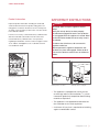
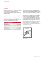
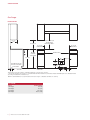
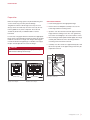
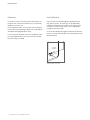
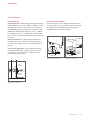
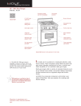
Gas Ranges Installation Guide GAS RANGES Contents Important Note 3Safety To ensure the safe and efficient installation of Wolf equipment, please take note of the following types of highlighted information throughout this guide: Precautions 4Specifications 7Installation 10Troubleshooting IMPORTANT NOTE highlights information that is especially relevant to a problem-free installation. CAUTION signals a situation where minor injury or product damage may occur if instructions are not followed. WARNING states a hazard that may cause serious injury or death if precautions are not followed. IMPORTANT NOTE: Throughout this guide, dimensions in parentheses are millimeters unless otherwise specified. 2 | Wolf Customer Care 800.222.7820 SAFETY PRECAUTIONS Product Information Important product information including the model and serial number are listed on the product rating plate. The rating plate is located on the bottom of the control panel assembly, at the far right, just above the oven door. Refer to the illustration below. If service is necessary, contact Wolf factory certified service with the model and serial number. For the name of the nearest Wolf factory certified service or for questions regarding the installation, visit the contact & support section of our website, wolfappliance.com or call Wolf customer care at 800-222-7820. RATING PLATE IMPORTANT INSTRUCTIONS WARNING A child or adult can tip this appliance and be killed. Verify the anti-tip device has been properly installed and engaged. Ensure the anti-tip device is re-engaged when this appliance is moved. Refer to the illustrations below for how to verify correct installation. To reduce the risk of burns, do not move this appliance while hot. Do not operate this appliance without the antitip device in place and engaged. Failure to do so can result in death or serious burns to children or adults. Rating plate location. ANTI-TIP DEVICE Anti-tip device location. ANTI-TIP DEVICE ENGAGED Anti-tip device engaged. •This appliance is equipped with casters on two or more legs and must be installed on 1/8" (3) thick commercial grade vinyl composition floor finishing materials or equivalent. •This appliance is not approved for downward airflow ventilation or air curtain equivalent. •A minimum 20" (508) riser is required when installing against a combustible surface. wolfappliance.com | 3 SPECIFICATIONS Electrical Installation must comply with all applicable electrical codes. Locate the electrical supply flush with the wall or floor and within the shaded area shown in the illustration on page 6. A separate circuit, servicing only this appliance is required. A ground fault circuit interrupter (GFCI) is not recommended and may cause interruption of operation. ELECTRICAL REQUIREMENTS GAS RANGE Electrical Supply Service Receptacle Power Cord 4 | grounded, 110/120 V AC, 60 Hz 15 amp dedicated circuit 3-prong grounding-type 6' (1.8 m) Wolf Customer Care 800.222.7820 SPECIFICATIONS Gas Supply Installation must conform with local codes or, in the absence of local codes, with the National Fuel Gas Code. Locate the gas supply within the shaded area shown in the illustration on page 6. The range is equipped for use with natural or liquid propane (LP) gas. It is design certified by the Canadian Standards Association (CSA) for natural or LP gases. The product rating plate has information on the type of gas that should be used. For rating plate location, refer to the illustration on page 3. If this information does not agree with the type of gas available, check with the local gas supplier. The range must be connected to a regulated gas supply. The supply line must be equipped with an approved external gas shut-off valve located near the range in an accessible location. Do not block access to the shut-off valve. Refer to the illustration below. A gas supply line of 3/4" (19) rigid pipe must be provided to the range. If local codes permit, a certified, 3' (.9 m) long, 1/2" (13) or 3/4" (19) ID flexible metal appliance connector is recommended to connect the units 1/2" NPT female inlet to the gas supply line. Pipe joint compounds, suitable for use with natural or LP gas should be used. Wolf natural and LP gas ranges will function up to 10,250' GAS SUPPLY REQUIREMENTS (3124 m) in altitude without adjustment. If the installation NATURAL GAS Gas Supply Pressure Min Line Pressure Max Pressure to Regulator 5" (12.5 mb) WC 7" (17.5 mb) WC 14" (34.9 mb) WC, .5 psi (3.5 kPa) exceeds this elevation, contact an authorized Wolf dealer for a high altitude conversion kit. LP GAS Gas Supply Pressure Min Line Pressure Max Pressure to Regulator 10" (25 mb) WC 11" (27.4 mb) WC 14" (34.9 mb) WC, .5 psi (3.5 kPa) SHUT-OFF VALVE OPEN POSITION TO APPLIANCE GAS SUPPLY Gas shut-off valve. wolfappliance.com | 5 SPECIFICATIONS Gas Range INSTALLATION 13" (330) 30" (762) TO 36" (914) max TO BOTTOM OF VENTILATION HOOD** 18" (457) min 6" (152) TO COMBUSTIBLE* 36" (914) FLOOR TO COUNTERTOP 6" (152) TO COMBUSTIBLE* OPENING WIDTH 37" (940) 12" 10" (254) (305) (76) SIDE VIEW E 7 3/4" (197) 2" (51) (146) LOCATION OF GAS AND ELECTRICAL EXTENDS ON FLOOR 3" 5 3/4" FRONT VIEW G 12" (305) 5" (127) *Min clearance from rough opening to combustible materials up to 18" (457) above countertop. **42" (1067) min clearance from countertop to combustible materials without ventilation hood. Charbroiler models and GR488 require non-combustible material above range if installed without ventilation hood. NOTE: For island installations, 12" (305) min clearance from back of range to combustible rear wall above countertop. GAS RANGE WIDTH 30" Range 36" Range 48" Range 60" Range 6 | Wolf Customer Care 800.222.7820 OPENING WIDTH 30" (762) 36" (914) 48" (1219) 60 1/4" (1530) INSTALLATION Preparation Before moving the range, protect any finished flooring and secure oven door(s) closed to prevent damage. To lighten the load or to fit through a door way, the oven door(s) can be removed. Only remove if necessary. Do not remove griddle or any other component. Door removal should only be done by a certified installer or service technician. For removal, a hinge pin will be inserted into the appropriate hinge shown in the illustrations below. The pin(s) are located inside the oven door. For single oven ranges, the hinge pin must be inserted in the right hinge. For double oven ranges, the pins must be placed in the outer two hinges. CAUTION OVEN DOOR REMOVAL 1 Insert the hinge pin into the appropriate hinge. 2Remove the lower kickplate assembly to access the lower hinge retainer mounting screws. 3Open the oven door and remove both upper and lower hinge retainer mounting screws. The oven gasket may have to be moved slightly to access the bottom screws. 4Move the hinge retainer plate forward slightly. The hinge retainer plate will remain on the door hinge after the mounting screws have been removed. 5Carefully close the oven door to approximately 60°, then lift the door up and out. A slight rocking motion may be required for removal. Failure to insert the hinge pin in the appropriate hinge arm will cause damage to the range. SPRING HINGES HINGE RETAINER PLATE UPPER MOUNTING SCREW HINGE PIN KICKPLATE SPRING HINGE Single oven ranges. SPRING HINGES Oven door removal. Double oven ranges. SPRING HINGE wolfappliance.com | 7 INSTALLATION Placement Anti-Tip Bracket Do not lift or carry the oven door by the door handle. The range has rear casters which allow for easy movement by lifting the front of the unit. Raise the unit to its desired height by adjusting the front legs and rear casters. The front legs can be adjusted by rotating the hexagonal leg clockwise to raise and counterclockwise to lower. The rear casters can be adjusted by rotating the wheel assembly. Use an appliance dolly to move the unit near the opening. Remove and recycle packing materials. Do not discard the anti-tip bracket supplied with the range. If a riser has been specified, refer to the installation instructions packaged with the riser. The riser must be installed before the range is installed. To ensure the anti-tip bolt engages the bracket, position the bracket 3" (76) from the left side of the opening. Refer to the illustration below. ANTI-TIP BRACKET 3" (76) Anti-tip bracket location. 8 | Wolf Customer Care 800.222.7820 INSTALLATION Anti-Tip Bracket INSTALL BRACKET ANTI-TIP BOLT ADJUSTMENT Drywall application | After properly positioning the anti-tip bracket, mark holes, then use a Philips screwdriver or a low rpm power drill to drive the wall anchor into the surface of the wallboard until flush. Pre-drill holes if needed. For hard wallboard or double-board construction, use a 1/4" drill bit. For solid plaster, use a 7/16" drill bit. Refer to the illustration below. Use #8 screws and flat washers to fasten the bracket to the wall. Once the bracket is secure, adjust the anti-tip bolt so the top of the washer is 7/8" (22) maximum from the floor. Slide the range into the opening and verify the anti-tip bolt is engaged. Refer to the illustrations below. Wood floor application | After properly positioning the anti-tip bracket, drill 3/16" (5) pilot holes through the floor. Use #12 screws and flat washers to secure the bracket to the floor. Concrete floor application | After properly positioning the anti-tip bracket drill 3/8" (10) holes into the concrete a minimum of 1 1/2" (38) deep. Use 3/8" wedge anchors to secure the bracket to the floor. ANTI-TIP BOLT 7/8" (22) MAX Anti-tip bolt adjustment. ANTI-TIP DEVICE ENGAGED Anti-tip bolt engaged. WALL ANCHOR ANTI-TIP BRACKET Wall anchor installation. wolfappliance.com | 9 INSTALLATION Gas Supply Connection Troubleshooting All connections to the gas piping must be wrench-tightened. Do not overtighten or allow pipes to turn when tightening. IMPORTANT NOTE: If the range does not operate properly, follow these troubleshooting steps: If a flexible metal connector is being used, verify it is not kinked, then attach the gas supply line to the regulator on the range. Open the valve and check for leaks by placing a liquid detergent solution onto all gas connections. Bubbles around connections indicate a gas leak. If a leak appears, close the shut-off valve and adjust connections. •Verify electrical power is supplied to the range. 10 | Wolf Customer Care 800.222.7820 •Verify the gas supply shut-off valve is in the open position. •If the range does not operate properly, contact Wolf factory certified service. Do not attempt to repair the range. Wolf is not responsible for service required to correct a faulty installation. Wolf, Wolf & Design, Wolf Gourmet, W & Design and the color red as applied to knobs are registered trademarks and service marks of Wolf Appliance, Inc. Sub-Zero, Sub-Zero & Design, Dual Refrigeration, Constant Care, The Living Kitchen, Great American Kitchens The Fine Art of Kitchen Design, and Ingredients are registered trademarks and service marks of Sub-Zero, Inc. (collectively, the “Company Marks.”) All other trademarks or registered trademarks are property of their respective owners in the United States and other countries. WOLF APPLIANCE, INC. P.O. BOX 44848 MADISON, WI 53744 819488 REV-C WOLFAPPLIANCE.COM 12 / 2012 800.222.7820