1
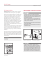
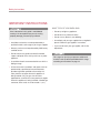
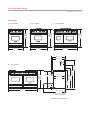
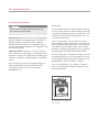
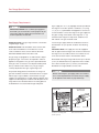
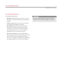
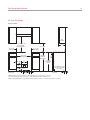
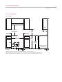
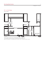
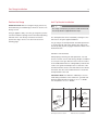
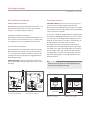
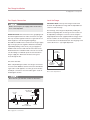
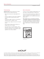
INSTALLATION GUIDE
Gas Ranges
Contents
Important Note
Wolf Gas Ranges . . . . . . . . . . . . . . . . . . . . . . . . . . . . . 3
To ensure the safe and efficient use of Wolf equipment,
please take note of the following types of highlighted
information throughout this guide:
Safety Instructions . . . . . . . . . . . . . . . . . . . . . . . . . . . . 4
Gas Range Specifications . . . . . . . . . . . . . . . . . . . . . . 5
Gas Range Installation . . . . . . . . . . . . . . . . . . . . . . . . 14
IMPORTANT NOTE highlights information that is especially
important.
Service Information . . . . . . . . . . . . . . . . . . . . . . . . . . . 19
CAUTION signals a situation where minor injury or product
damage may occur if instructions are not followed.
Features and specifications are subject to change at any time
without notice. Visit wolfappliance.com/specs for the most
up-to-date information.
WARNING states a hazard that may cause serious injury or
death if precautions are not followed.
IMPORTANT NOTE: Throughout this guide, dimensions in
parentheses are millimeters unless otherwise specified.
Wolf Gas Ranges
3
wolfappliance.com/specs
Gas Range Installation
IMPORTANT INSTRUCTIONS
IMPORTANT NOTE: This installation must be completed
by a qualified installer, service agency or gas supplier.
Read this entire installation guide prior to installation and
save for the local inspector’s reference. The homeowner
should keep this installation guide for future reference.
This appliance must be installed in accordance with
National Electrical Codes, as well as all state, municipal
and local codes. The correct voltage, frequency and
amperage must be supplied to the appliance from a dedicated, grounded circuit which is protected by a properly
sized circuit breaker or time delay fuse. The proper
voltage, frequency and amperage ratings are listed on the
product rating plate.
Wolf gas ranges are manufactured for use with natural gas
or LP gas. Check the product rating plate for the type of
gas for your specific model. If this appliance does not
correspond to your type of gas, contact your authorized
Wolf dealer.
A child or adult can tip the range and be killed.
Verify the anti-tip device has been properly installed
and engaged. See the illustrations below for how to
verify correct installation.
Ensure the anti-tip device is re-engaged when the
range is moved. See the illustrations below for how
to verify correct installation.
Do not operate the range without the anti-tip device
in place and engaged.
Failure to do so can result in death or serious burns
to children or adults.
Record the model and serial numbers before installing the
gas range. Both numbers are listed on the product rating
plate, located under the drip pan that supports the burner
grates, inside the left side panel of the range. Refer to the
illustration below.
Wolf Gas Range
ANTI-TIP
DEVICE
ANTI-TIP
DEVICE
ENGAGED
Model Number
Serial Number
Location of anti-tip device.
RATING PLATE
Location of rating plate
(inside panel).
Anti-tip device engaged.
To reduce the risk of burns, do not move this
apppliance while hot. This appliance is provided
with casters to facilitate movement. To reduce the
risk of injury due to tipping of the appliance, verify
the reinstallation of this appliance into the anti-tip
device provided, and lock the casters after returning the appliance to the original installed position.
Safety Instructions
4
IMPORTANT INSTRUCTIONS
WHAT TO DO IF YOU SMELL GAS:
If the information in this guide is not followed
exactly, a fire or explosion may result, causing
property damage, personal injury or death.
• Do not try to light any appliance.
• Do not touch any electrical switch.
• Do not use any phone in your building.
• Immediately call your gas supplier from a neighbor’s
• Installation and service must be performed by a
qualified installer, service agency or the gas supplier.
• Warranty service must be performed by Wolf factory
phone. Follow the gas supplier’s instructions.
• If you cannot reach your gas supplier, call the fire
department.
certified service.
• Do not store or use gasoline or other flammable
vapors and liquids in the vicinity of this or any other
appliance.
• A ventilation hood is recommended for use with the
Wolf gas range.
• In Massachusetts: Installations and repairs must be
performed by a qualified or licensed contractor,
plumber or gasfitter qualified or licensed by the
state, province or region where this appliance is
being installed. Only use gas shut-off valves
approved for use within the state, province or region
where this appliance is being installed. A flexible gas
connector, when used, must not exceed 3' (.9 m).
This range can tip. Injury to persons could result.
Install the anti-tip device provided with this range
according to instructions on page 14.
Gas Range Specifications
5
wolfappliance.com/specs
Gas Ranges
30" (762) RANGE
36" (914) RANGE
48" (1219) RANGE
37" (940)
HEIGHT TO
COOKING
SURFACE
37" (940)
HEIGHT TO
COOKING
SURFACE
37" (940)
HEIGHT TO
COOKING
SURFACE
36" (914)
30" (762)
48" (1219)
28 3/8" (721)
27 1/4" (692)
9 1/4"
(235)
60" (1527) RANGE
56 3/4"
(1441)
20"
RISER
46 3/4"
37" (940)
HEIGHT TO
COOKING
SURFACE
36" (914)
(1187)
10"
RISER
24 1/2" (622)
41 3/4"
25 1/4" (641)
(1060)
5"
RISER
37 3/4"
(959)
ISLAND
TRIM
2 1/2"
(64)
60" (1524)
43 3/8" (1102)
LEGS AND CASTERS ALLOW
1" (25) HEIGHT ADJUSTMENT
SIDE VIEW—ALL RANGES
Gas Range Specifications
6
Installation Requirements
VENTILATION
Failure to locate the range without the proper clearances will result in a fire hazard.
IMPORTANT NOTE: Caution must be used in planning the
proper installation of the Wolf gas range to avoid fires or
damage to adjacent cabinetry or kitchen equipment.
Follow all minimum clearances to combustible surfaces
shown in the installation illustration for your specific model
on the following pages.
IMPORTANT NOTE: A minimum 5" (127) riser is required
when installing a gas range against a combustible surface.
A minimum 10" (254) riser is required when installing a gas
range with a charbroiler or griddle against a combustible
surface.
Risers and other accessories are available through your
authorized Wolf dealer. For local dealer information,
visit the find a showroom section of our website,
wolfappliance.com.
The gas range must have an adequate supply of fresh air
to assure proper combustion and ventilation. The location
of the range should be away from strong draft areas, such
as windows, doors and strong heating vents or fans. Do
not obstruct the flow of air.
For the cooking surface, fresh air intakes are located
below the bullnose and control knobs. For the oven, there
are fresh air intakes at the bottom front of the kick panel.
Never block the fresh air intakes. Most of the heated air
and burner combustion by-products from the oven(s) exit
through the back riser. Refer to the illustration below.
Due to the high volume of ventilation air required, a source
of outside replacement air is recommended. This is especially important for tightly sealed and insulated homes. A
qualified HVAC contractor should be consulted.
It is recommended that you use a Wolf pro ventilation
hood or hood liner with the Wolf gas range. Refer to the
Wolf ventilation guide.
HEATED AIR EXITS
AIR INTAKES
Air intakes and exits (optional
riser shown).
Gas Range Specifications
7
wolfappliance.com/specs
Electrical Requirements
ELECTRICAL SHOCK HAZARD: Plug into a grounded
3-prong outlet. Do not remove ground prong. Do not
use an adapter. Failure to follow these instructions can
result in electric shock, fire or death.
The Wolf gas range requires a 110/120 V AC, 50/60 Hz
electrical supply to operate the electronic ignition system.
The service should have its own 15 amp circuit breaker. A
ground fault circuit interrupter (GFCI) is not recommended
and may cause interruption of operation.
The power cord is equipped with a 3-prong, grounding
plug for protection against shock hazard. The power cord
must be plugged into a mating 3-prong grounded outlet,
grounded to conform with the National Electrical Code,
ANSI/NFPA 70 latest edition, or Canadian Electrical Code
(CSA) and all local codes and ordinances. Refer to the
illustration below.
IMPORTANT NOTE: This appliance must be properly
grounded to avoid electrical shock hazard. Do not ground
to a gas pipe.
GROUNDING
PLUG
GROUNDED
ELECTRICAL OUTLET
Electrical ground.
IMPORTANT NOTE: You must follow all National Electrical
Code regulations. In addition, be aware of local codes and
ordinances when installing your service.
WIRING DIAGRAM
The wiring diagram covering the control circuit is located
inside the lower panel of the gas range, below the oven
doors.
Gas Range Specifications
8
Gas Supply Requirements
EXPLOSION HAZARD: Use a certified gas supply line
and install a gas shut-off valve. Securely tighten all gas
connections. Failure to follow these instructions can
result in explosion, fire or death.
IMPORTANT NOTE: The gas range must be connected to
a regulated gas supply.
IMPORTANT NOTE: This installation must conform with
local codes and ordinances. In the absence of local
codes, installations must conform with the American
National Standard, National Fuel Gas Code.
The gas range is equipped for use with natural or liquid
propane (LP) gas. Conversions are required in order for
appliances designed for one gas to be operated with the
other gas. Such conversions must be performed by Wolf
factory certified service. Make sure your gas range is
correctly adjusted for the type of gas being used.
The product rating plate has information on the type of
gas that should be used. If this information does not agree
with the type of gas available, check with the local gas
supplier. The rating plate is located under the drip pan that
supports the burner grates, inside the left side panel of the
range. Refer to the illustration below. The rating plate for
model R482CF is located inside the right side panel.
A gas supply line of 3/4" (19) rigid pipe must be provided to
the range. If local codes permit, a certified, 3' (.9 m) long,
1/2" (13) or 3/4" (19) ID flexible metal appliance connector is
recommended to connect the range to the gas supply line.
The pipe coming out the back of the range has 1/2" (13)
female threads. Pipe joint compounds, suitable for use
with natural or LP gas should be used.
Locate the gas supply within the shaded area shown in
the illustration for your specific model on the following
pages.
IMPORTANT NOTE: The supply line must be equipped
with an approved external gas shut-off valve located near
the range in an accessible location. Do not block access
to the shut-off valve. Refer to the illustration below.
Wolf natural and LP gas ranges will function up to 10,250'
(3124 m) in altitude without any adjustment. If the installa-
tion is above 10,250' (3124 m), contact your authorized
Wolf dealer for a high altitude conversion kit.
Before connecting the gas supply, make sure all valves
are in a closed position. Do not connect the gas supply
to an appliance that shows any sign of damage.
RATING PLATE
SHUT-OFF VALVE
OPEN POSITION
TO APPLIANCE
Location of rating plate
(inside panel).
GAS SUPPLY
Gas shut-off valve.
Gas Range Specifications
9
wolfappliance.com/specs
Gas Supply Requirements
GAS MANIFOLD PRESSURE
• Natural Gas: Standard orifices are set for 5" (12.5 mb)
WC (water column). A natural gas pressure regulator is
installed.
• LP Gas: Standard orifices are set for 10" (25 mb) WC.
An LP gas pressure regulator is installed.
• Gas Supply Pressure: The maximum gas supply
pressure to the regulator should never exceed 14"
(34.9 mb) WC; .5 psi (3.5 kPa) for natural and LP gas.
The minimum line pressure is 7" (17.5 mb) WC for
natural gas and 11" (27.4 mb) WC for LP gas.
• Gas Pressure Regulator: To control and maintain a
uniform gas pressure in the gas manifold, the unit must
be used with a gas pressure regulator. The burner
orifices, etc. are sized for the gas pressure delivered by
the supplied regulator. Do not remove the regulator.
The maximum gas supply pressure to the regulator
should never exceed 14" (34.9 mb) WC; .5 psi (3.5 kPa).
Gas Range Specifications
10
30" (762) Gas Range
INSTALLATION
SIDE
CABINET
13" (330)
30" (762) TO 36" (914)
max
TO BOTTOM OF
VENTILATION HOOD**
18" (457) min
6" (152) TO
COMBUSTIBLE*
6" (152) TO
COMBUSTIBLE*
30 1/4" (768)
OPENING WIDTH
10" (254)
36" (914)
FLOOR TO
COUNTERTOP
37" (940)
TO COOKING
SURFACE
12"
(305)
5 3/4"
(146)
7 3/4" (197)
FRONT VIEW
E
2" (51)
G
12"
(305)
LOCATION OF GAS AND
ELECTRICAL EXTENDS
ON FLOOR
5"
(127)
SIDE VIEW
*Minimum clearance from rough opening to combustible materials up to 18" (457) above countertop.
**36" (914) minimum clearance from countertop to combustible materials without ventilation hood.
NOTE: For island installations, 12" (305) minimum clearance from back of range to combustible rear wall above countertop.
3"
(76)
Gas Range Specifications
11
wolfappliance.com/specs
36" (914) Gas Range
INSTALLATION
SIDE
CABINET
13" (330)
30" (762) TO 36" (914)
max
TO BOTTOM OF
VENTILATION HOOD**
18" (457) min
6" (152) TO
COMBUSTIBLE*
6" (152) TO
COMBUSTIBLE*
36 1/4" (921)
OPENING WIDTH
10" (254)
36" (914)
FLOOR TO
COUNTERTOP
37" (940)
TO COOKING
SURFACE
12"
(305)
5 3/4"
(146)
7 3/4" (197)
FRONT VIEW
E
LOCATION OF GAS AND
ELECTRICAL EXTENDS
ON FLOOR
2" (51)
G
12"
5"
(305)
(127)
SIDE VIEW
*Minimum clearance from rough opening to combustible materials up to 18" (457) above countertop.
**36" (914) minimum clearance, 44" (1118) for charbroiler, from countertop to combustible materials without ventilation hood.
NOTE: For island installations, 12" (305) minimum clearance from back of range to combustible rear wall above countertop.
3"
(76)
Gas Range Specifications
12
48" (1219) Gas Range
INSTALLATION
SIDE
CABINET
13" (330)
30" (762) TO 36" (914)
max
TO BOTTOM OF
VENTILATION HOOD**
18" (457) min
6" (152) TO
COMBUSTIBLE*
6" (152) TO
COMBUSTIBLE*
48 1/4" (1226)
OPENING WIDTH
26" (660)
37" (940)
TO COOKING
SURFACE
12" (305)
5 3/4"
(146)
7 3/4" (197)
FRONT VIEW
36" (914)
FLOOR TO
COUNTERTOP
E
LOCATION OF GAS AND
ELECTRICAL EXTENDS
ON FLOOR
2" (51)
G
12"
5"
(305)
(127)
*Minimum clearance from rough opening to combustible materials up to 18" (457) above countertop.
**36" (914) minimum clearance, 44" (1118) for charbroiler, from countertop to combustible materials without ventilation hood.
NOTE: For island installations, 12" (305) minimum clearance from back of range to combustible rear wall above countertop.
SIDE VIEW
3"
(76)
Gas Range Specifications
13
wolfappliance.com/specs
60" (1527) Gas Range
INSTALLATION
SIDE
CABINET
13" (330)
30" (762) TO 36" (914)
max
TO BOTTOM OF
VENTILATION HOOD**
18" (457) min
6" (152) TO
COMBUSTIBLE*
6" (152) TO
COMBUSTIBLE*
60 1/4" (1530)
OPENING WIDTH
10" (254)
36" (914)
FLOOR TO
COUNTERTOP
37" (940)
TO COOKING
SURFACE
12"
(305)
5 3/4"
(146)
E
LOCATION OF GAS AND
ELECTRICAL EXTENDS
ON FLOOR
2" (51)
7 3/4" (197)
FRONT VIEW
G
12"
5"
(305)
(127)
*Minimum clearance from rough opening to combustible materials up to 18" (457) above countertop.
**44" (1118) minimum clearance from countertop to combustible materials without ventilation hood.
NOTE: For island installations, 12" (305) minimum clearance from back of range to combustible rear wall above countertop.
SIDE VIEW
3"
(76)
Gas Range Installation
Position the Range
IMPORTANT NOTE: Before moving the range, protect any
finished flooring to avoid damage to the floor. Secure oven
door(s) closed.
Using an appliance dolly, move the gas range into position
near the installation opening. Remove and discard packing
materials. If the oven door(s) need to be removed to
position the range, refer to oven door removal on the
following page.
14
Anti-Tip Bracket Installation
This range can tip. Injury to persons could result. Install
the anti-tip bracket supplied with the range.
The anti-tip bracket can be installed by securing it to the
wall or floor using the supplied hardware.
For gas ranges, the anti-tip bracket should be positioned
3" (76) from the left side of the opening. This will ensure
the anti-tip bolt properly engages the bracket. Refer to the
illustration below.
DRYWALL APPLICATIONS
After properly positioning the anti-tip bracket, use wall
anchors to fasten it to the wall. Using a Philips screwdriver
or a low rpm screw gun, drive the anchor into the surface
of the wallboard until the two cutting blades penetrate the
surface. Use gentle forward pressure to rotate the collar
until flush with the surface of the wall. Refer to the illustration below. Use #8 screws and flat washers to fasten the
anti-tip bracket to the wall.
IMPORTANT NOTE: Pre-drill holes if difficulty is encountered during installation of the wall anchor. For hard wallboard or double-board construction, use a 1/4" drill bit.
For solid plaster, use a 7/16" drill bit.
WALL
ANCHOR
ANTI-TIP
BRACKET
3" (76)
Anti-tip bracket location.
ANTI-TIP
BRACKET
Wall anchor installation.
Gas Range Installation
15
wolfappliance.com/specs
Anti-Tip Bracket Installation
Oven Door Removal
WOOD FLOOR APPLICATIONS
IMPORTANT NOTE: Remove the oven door(s) only if it is
necessary to fit the range through a tight doorway.
Removal may cause damage to the porcelain oven interior
or the door(s). Door removal should be done by a qualified
service technician or installer.
After properly positioning the anti-tip bracket, drill 3/16" (5)
pilot holes through the floor. Use #12 screws and flat
washers to secure the bracket to the floor.
CONCRETE FLOOR APPLICATIONS
After properly positioning the anti-tip bracket drill 3/8" (10)
holes into the concrete a minimum of 11/2" (38) deep. Use
3/8" wedge anchors to secure the bracket to the floor.
ANTI-TIP BOLT ADJUSTMENT
Once the bracket is secured in place, adjust the anti-tip
bolt at the back of the range so the top of the washer is
7/8" (22) maximum from the floor. Slide the range into the
opening and verify the anti-tip bolt is engaged. Refer to
the illustrations below.
IMPORTANT NOTE: The top of the range must be level.
Use the adjustable front legs and the rear casters to level
the range.
ANTI-TIP
BOLT
7/8" (22) MAX
Anti-tip bolt adjustment.
For removal, a hinge pin (supplied with the range) must be
inserted in the appropriate hinge arm. For each oven door,
only one hinge arm is spring loaded, requiring use of the
hinge pin for removal of the oven door. The hinge pin can
be found taped to the inside of the oven door.
For single oven ranges, the hinge pin will be inserted
through the hole in the right hinge arm (facing the range).
For double oven ranges, the spring hinges are located on
the outer edges of the unit. The left oven door will have
the spring hinge on the left side and the right oven door
will have the spring hinge on the right side. Refer to the
illustrations below.
Failure to insert the hinge pin in the appropriate hinge
arm will cause damage to the range.
ANTI-TIP
DEVICE
ENGAGED
SPRING HINGE
SPRING HINGES
Single oven ranges.
Double oven ranges.
Anti-tip bolt engaged.
Gas Range Installation
16
Oven Door Removal
OVEN DOOR REMOVAL
OVEN DOOR REINSTALLATION
1) Remove the lower kickplate assembly.
1) Hold the oven door on both sides and position it with
door hinges aligned with openings in the oven frame.
2) Open the oven door all the way and insert the door
hinge pin through the hole in the appropriate hinge
arm. Refer to the illustration below.
3) Remove both upper and lower hinge retainer mounting
screws. The oven gasket may have to be moved
slightly to access the bottom screws.
4) Move the hinge retainer plate forward slightly. The
hinge retainer plate will remain on the door hinge after
the mounting screws have been removed.
5) Carefully close the oven door to approximately 60°
from horizontal and lift the door away from the oven.
A slight racking motion may be required for removal.
Do not lift or carry the oven door by the door handle.
HINGE
RETAINER
PLATE
UPPER
MOUNTING
SCREW
HINGE
PIN
KICKPLATE
Oven door removal.
2) Holding the oven door at an approximate 30° angle
from vertical, slide the hinges into the openings
until the bottom hinge arms drop fully into the hinge
receptacles.
3) Open the oven door to its fully opened position.
Remove the hinge pin from the appropriate hinge arm.
4) Reinstall the hinge retainer plate with upper and lower
mounting screws.
5) Open and close the door completely to ensure that it is
properly installed.
6) Reinstall the lower kickplate assembly.
Gas Range Installation
17
wolfappliance.com/specs
Gas Supply Connection
Level the Range
Before connecting the gas supply, make sure all valves
are in a closed position.
IMPORTANT NOTE: All connections to the gas piping must
be wrench-tightened. Do not make connections too tight,
this may crack the regulator and cause a gas leak. Do not
allow the pipes to turn when tightening fittings.
Assemble the flexible metal connector from the gas supply
pipe to the gas pressure regulator. Determine the fittings
required depending on the size of your gas supply line,
flexible metal connector and shut-off valve. Refer to the
illustration below. If a flexible metal connector is used, be
sure the tubing is not kinked. Open the shut-off valve in
the gas supply line. Wait a few minutes for the gas to
move through the line.
GAS LEAK TESTING
Brush a liquid detergent solution onto all gas connections
to test for leaks. Bubbles around connections will indicate
a gas leak. If a leak appears, close the gas shut-off valve
and adjust connections. Check for leaks again. Clean off
the detergent solution.
Never test for a gas leak with a match or other flame.
GAS PRESSURE
REGULATOR
SHUT-OFF
VALVE
ADAPTER
NIPPLE
ADAPTER
FLEXIBLE
METAL CONNECTOR
Gas supply line connection.
ELBOW
IMPORTANT NOTE: The top of the range must be level.
Use both the adjustable front legs and the adjustable rear
casters to level the range.
The front legs of the range are adjusted by rotating the
bottom hexagonal portion of the leg. The rear casters can
be adjusted by rotating the nut on the caster. Using the
height adjustment wrench (supplied with the range), rotate
the nut clockwise to raise the range or counterclockwise
to lower. Refer to the illustration below. The range legs and
casters allow for a 1" (25) height adjustment.
CASTER
ADJUSTMENT
HEIGHT
ADJUSTMENT
WRENCH
Rear caster adjustment.
Gas Range Installation
Verify Range Operation
IMPORTANT NOTE: Prior to operating the range, be sure
to read the entire Wolf gas ranges use & care guide
included with the range for important safety, service and
warranty information.
SURFACE BURNERS
Place the burner parts on each burner base and position
the burner grates before lighting.
Surface burners of the gas range use electronic igniters.
When the control knob is pushed in and turned to the
HIGH position, the system creates a spark to light the
burner. This sparking continues until the electronic ignition
senses a flame.
To check operation of the surface burners, push in and
turn each control knob to the HIGH position. The flame
should light within four seconds.
If the burners do not light properly, turn control knobs to
the OFF position. Check that burner parts are in the
proper position. Make sure electricity is being supplied to
the range and that the gas shut-off valve is in the open
position. Check operation again, waiting at least five
minutes; if the burners still do not light properly, contact
Wolf factory certified service.
IMPORTANT NOTE: Initial lighting of the surface burners
may take slightly longer, as air in the system must be
purged before gas can be supplied to the burner.
OVEN OPERATION
Turn the oven(s) on and verify that they are coming up to
temperature. Refer to the Wolf gas ranges use & care
guide for additional information.
IMPORTANT NOTE: A small amount of smoke and odor
may be noticed during the initial break-in period.
18
Range Removal
Unplug the range and disconnect the gas supply line
before removing.
If removal of the gas range is necessary for cleaning or
service, shut off the gas supply. Unplug the range and
disconnect the gas supply line. Remove the range. Reinstall in the reverse order and be sure to check gas
connections for leaks.
Refer to the Wolf gas ranges use & care guide for cleaning
recommendations.
Service Information
19
wolfappliance.com/specs
Troubleshooting
Service Information
IMPORTANT NOTE: If the gas range does not operate
properly, follow these troubleshooting steps:
If service is necessary, maintain the quality built into your
gas range by contacting Wolf factory certified service.
• Verify that electrical power is being supplied to the
range.
For the name and number of Wolf factory certified service
nearest you, check the contact & support section of our
website, wolfappliance.com or call Wolf customer care at
800-222-7820.
• If nuisance clicking occurs when power is supplied to
the range, check the electrical outlet for reverse
polarity.
• Check the gas supply connections to ensure that the
installation has been completed correctly.
• Check that the gas supply shut-off valve is in the open
position.
• Follow troubleshooting procedures outlined in the
Wolf gas ranges use & care guide.
• If the range still does not operate properly, contact
Wolf factory certified service. Do not attempt to repair
the range yourself. Wolf is not responsible for service
required to correct a faulty installation.
When calling for service, you will need the model and
serial numbers of the gas range. Both numbers are listed
on the product rating plate, located under the drip pan
that supports the burner grates, inside the left side panel
of the range. Refer to the illustration below. The rating
plate for model R482CF is located inside the right side
panel.
RATING PLATE
Location of rating plate
(inside panel).
The information and images in this guide are the copyright property of Wolf Appliance, Inc. Neither this guide nor any information or images contained herein
may be copied or used in whole or in part without the express written permission of Wolf Appliance, Inc. ©Wolf Appliance, Inc. all rights reserved.
Wolf, Wolf & Design, Wolf Gourmet, W & Design and the color red as applied to knobs are registered trademarks and service marks of Wolf Appliance, Inc.
Sub-Zero, Sub-Zero & Design, Dual Refrigeration, Constant Care and The Living Kitchen are registered trademarks and service marks of Sub-Zero, Inc.
(collectively, the “Company Marks.”) All other trademarks or registered trademarks are property of their respective owners in the United States and other countries.
WOLF APPLIANCE, INC.
P. O. BOX 44848 MADISON, WI 53744
821111 REV-A
1/ 2012
WOLFAPPLIANCE.COM
800.222.7820