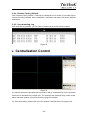
1
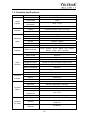
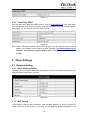
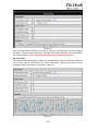
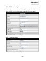
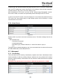
N7405JV INSTRUCTION MANUAL IP CAMERA Index 1 2 3 INTRODUCTION................................................................................................................ 1 1.1 THE PACKAGE INCLUDES ............................................................................................... 1 1.2 FUNCTION AND FEATURES ............................................................................................. 1 1.3 FUNCTION AND FEATURES ............................................................................................. 2 APPEARANCE AND INTERFACE.................................................................................... 3 2.1 APPEARANCE ............................................................................................................... 3 2.2 EQUIPMENT INTERFACE ............................................................................................... 3 CONNECT TO IP CAMERA OVER A LAN ....................................................................... 4 3.1 LAN CONNECTION ......................................................................................................... 4 3.2 SEARCH AND SET THE IP ADDRESS OF THE IP CAMERA .................................................... 4 3.3 VIEW IP CAMERA VIDEO FEED....................................................................................... 5 3.3.1 Video Display .......................................................................................................... 6 4 CONNECT TO IP CAMERA OVER A WAN ...................................................................... 7 4.1 WAN (WIDE AREA NETWORK) CONNECTION .................................................................. 7 4.2 PORT FORWARDING ...................................................................................................... 8 4.3 DDNS ......................................................................................................................... 8 4.3.1 Manufacturer’s DDNS............................................................................................. 8 4.3.2 Third Party DDNS ................................................................................................... 9 5 OTHER SETTINGS............................................................................................................ 9 5.1 NETWORK SETTING....................................................................................................... 9 5.1.1 Basic Network Setting............................................................................................. 9 5.1.2 WiFi Setting............................................................................................................. 9 5.1.3 ADSL Setting ........................................................................................................ 10 5.1.4 UPnP Setting ........................................................................................................ 10 5.1.5 DDNS Setting ........................................................................................................11 5.1.6 MSN Setting...........................................................................................................11 5.2 ALARM SETTINGS ........................................................................................................11 5.2.1 Alarm Setting .........................................................................................................11 5.2.2 Mail Service Setting .............................................................................................. 13 5.2.3 FTP Service Setting .............................................................................................. 13 5.2.4 Alarm Server......................................................................................................... 14 5.3 ADVANCED ................................................................................................................. 14 5.3.1 User Setting .......................................................................................................... 14 5.3.2 Multi Device Setting .............................................................................................. 15 5.4 MAINTAIN ................................................................................................................... 16 5.4.1 Device Information................................................................................................ 16 5.4.2 Time Setting.......................................................................................................... 16 5.4.3 Firmware upgrade................................................................................................. 16 5.4.4 Restore Factory Default........................................................................................ 17 5.4.5 User browsing Log................................................................................................ 17 6 CENTRALIZATION CONTROL....................................................................................... 17 7 FAQ.................................................................................................................................. 18 1 Introduction The IP Camera combines a high quality digital video camera with network connectivity and a powerful web server to bring clear video to your desktop from anywhere on your local network or over the Internet. 1.1 The package includes IP Camera * 1 IP Camera Utility CD *1 5V Power Adapter *1 Mounting Stand* 1 RJ45 Cable * 1 Mounting Screws with wall anchors * 4 Quick Guide* 1 1.2 Function and Features The video is compressed by MJPEG. There are three video resolution options, VGA, QVGA, and QQVGA. User can change some parameters according to their demands to satisfy their visual preferences. With built-in Microphone, it enables the User to monitor audio at the site. User can also connect this equipment to a speaker, and it supports two-way intercom function. It uses TCP/IP network protocols and has an inner web server. Users can browse video through IE or other browsers. Data is transferred through one port; it is easy for user to configure the network setting. Supports 802.11b/g protocol, can build up wireless monitoring. Supports UPNP, port forwarding automatically on the router. Motion detection can detect the environmental situation. Infrared LED for night vision covers 5m area, to enable 24 hour monitoring. Supports mobile phone remote viewing Supports three levels of user authority. Supports upgrading online. A label on the bottom of each IP Camera lists the Device ID and DDNS. When IP Camera is connected to the internet, this URL can be used to visit the device. Manufacturer provides free software which supports Multi-view, Long time recording, video replay etc. -1- 1.3 Function and Features Item Image Capture Assistant Video and Audio Network Other Features Hardware Interface Physical Specs Software (PC Side) Sub Item Description Sensor CMOS sensor Total of pixel 300k Minimum illumination IR on,0 Lux Lens f=3.6mm, F=2.0, Fixed Iris Lighting 12 850nm Infrared LEDs, 5m range Lighting Control Auto control Resolution 640*480(VGA)/320*240(QVGA)/160*120(QQVGA) Compression MJPEG Frame rate 30fps Bit rate 128kbps ~ 5Mbps Image Rotation Mirror /Flip Audio Compression ADPCM Basic Protocols TCP/IP、UDP/IP、HTTP、SMTP、FTP、DHCP、 DDNS、UPNP、NTP、PPPOE Other Protocol 802.11b/g Video control Supports Dual way audio Supports Motion Detection Supports Triggered Actions Email/FTP/ send message to alarm server User Setting Three levels Date/ Time Setting Supports Upgrade Upgrade from network DDNS Free DDNS provided by manufacturer Ethernet 10Base-T/100base-TX Audio In Internal mic Audio Out Audio Line-out interface x 1 Weight 120g Main body 48mm(L)*85mm(W)*110mm(H) Power DC 5V Power consumption <6W Operating temperature -20℃~50℃ Operating Humidity 10% ~ 80% non-condensing OS Supported Windows 98/2000/XP/Vista/ Win 7 etc. Browser IE 6.0 and Above or Compatible Browser, Firefox, Safari etc. Application Software IPCMonitor -2- 2 Appearance and Interface 2.1 Appearance Figure 1 Status Indicator: when device is running, flashes one or twice per second to indicate the wired network is connected; rapid flashing(2~3 times per second, indicates wireless network is connected. 2.2 Equipment interface Figure 2 -3- 3 Connect to IP Camera Over a LAN 3.1 Lan connection Figure 3 3.2 Search and set the IP address of the IP camera Run “BSearch_en.exe” from the support CD, the setting interface is as figure 4. Figure 4 Operation Steps: 1) Click “Search (F3) 2) Choose the device 3) Change the IP address of the IP camera according to the information in the red frame on the left. The numbers in the red circle should not be the same. -4- 4) 5) 6) Put the user name and password into “Authentication” (By default, the user name is: admin, password is: 123456). Click “Update” After successfully updating, click “Search (F3)”, choose the device and click “Browse (F4)”. Then you may view the IP camera, as shown in Figure 5. NOTE: 1) If you don’t know how to manually configure “IP config”, you can also tick the “Set IP automatically” box to get the IP address from the router automatically. 2) If you have firewall software on your PC, when you run BSearch_en.exe, it may pop up a window to ask “whether you want to block this program or not”, then you should choose not to block. 3) The default IP address is 192.168.0.178 and default http port is 80. Figure 5 3.3 View IP Camera Video Feed We suggest using the Internet Explore to view the camera video feed(it provides more functions, but User will need to install the Player software first. Click the “download and install player (first use)” link, it will pop up a dialogue box as in Figure 6, click Run, it will automatically download Player and install it. -5- Figure 6 3.3.1 Video Display After installing the software, click the “Mode 1 to view” link as in Figure 5 to view the camera video feed (see Figure 7). Figure 7 1) Main Menu The main menu includes the function settings of the submenus 2) Status Display The status display is in upper right corner, it shows the status of up to 9 devices: -6- if not connected, button is gray if connected, button is green If wrongly connected, button is yellow If alarm, button is red 3) Multi Device display area If User adds multiple devices (refer to section 5.3.2), when shifting to 4-Ch or 9-CH, it will automatically show additional devices. You select one device, and you can operate it using these keys: Play, Stop, and Record, Control Pan/Tilt, etc. These buttons mean start video, stop, monitor, talk, record and snapshot. Note: If you want to click this button to record video, please go to Advanced—Other Settings to set the Record Path first. Please see Figure 8 below. Figure 8 User can also set the device frame rate、resolution, brightness, contrast and other parameters. Note: This model has no Pan/Tilt or Alarm I/O function. You can control additional cameras using the Multi-view feature of the IP Camera software. 4 Connect to IP Camera Over a WAN 4.1 WAN (Wide Area Network) connection Figure 9 -7- 4.2 Port forwarding To view an IP Camera’s video feed from a WAN, you must enable port forwarding on the router the camera connects to. Using a Netgear router as an example: Figure 10 Setting Procedure: 1) After logging in to the router interface,choose “Port Forwarding” 2) Choose “Add custom Service” 3) Input IP camera port. 4) Input IP camera IP address,click “Apply” (the http port and ip address should be the same as in Figure 4 which can be set manually or automatically) Note: Different routers have different settings for port-forwarding; please consult your router manual for instructions on how to enable port-forwarding. After port-forwarding is enabled, you can view the IP Camera video feed over a WAN. 4.3 DDNS You can also use the manufacturer’s DDNS to access the camera as long as port-forwarding for it is configured. 4.3.1 Manufacturer’s DDNS The device manufacturer has provided a free DDNS. The User can find it in the Network menu, as shown in Figure 11. -8- Figure 11 4.3.2 Third Party DDNS User can also use a third part DDNS service, such as www.dyndns.com. User must apply for a free domain name from this website, enter the information for it and save the settings (see Figure 12). The domain name can then be used. Figure 12 Note: Using a third party domain name, if the http port is not 80, the port number must be added to the domain name following a colon. Example: http://btest.dyndns.biz:81. With the manufacturer-supplied DDNS there is no need to add the PORT number. 5 Other Settings 5.1 Network Setting 5.1.1 Basic Network Setting The user can also enter the Basic Network Settings to set the IP address without using the search software. See Figure 13 below. Figure 13 5.1.2 WiFi Setting If the camera is using a WiFi connection, enter Wireless Settings, as shown in Figure 14 below. Click the “Scan” button, it will show you all detected wireless networks in the -9- Wireless Network List box. Select one of them and tick “Using Wireless Lan”, then the relevant data of the selected wireless network will be shown in the adjacent fields. Enter the “Share Key” access password and click “Set”, the WiFi access configuration is now complete. Figure 14 Note1: When the device is connected both WiFi and wired networks, it will firstly try to connect to the wired network, if it doesn’t succeed, it will then try to connect to the WiFi. The IP address and port for both wireless and wired network are the same. Note2: Before you configure a wireless network as shown above; please make sure the camera is connected to the network via a network cable. After configuration succeeds, please reboot the camera and the wireless function takes effect. 5.1.3 ADSL Setting User can enable ADSL Dialup according to the Figure 15 below (the ADSL provider will assign a user name and password to you when you apply for ADSL service.) Connect the camera directly to the ADSL modem and it is then connected to the Internet. Figure 15 5.1.4 UPnP Setting If you enable UPNP, once the IP camera is connected to the LAN, it will communicate with the LAN router and set up port-forwarding automatically. In Figure 16 below, tick “Using UPNP to Map Port” and the setting is complete. You can check if the UPNP works or not in the System Maintenance interface. - 10 - Figure 16 Before using the UPNP function, please make sure the router’s UPNP function has been initialized. Not all routers support UPNP completely. Please test if the router works well with the camera equipment, if not, we suggest you disable this function and configure port-forwarding manually. 5.1.5 DDNS Setting Please refer to the content in section 4.3. 5.1.6 MSN Setting Figure 17 User needs to apply for an MSN account for this device first, for example: [email protected]. Please enter this MSN account and its password as in Figure 17 above. Then enter your MSN account, for example: [email protected], in the ‘MSN Friends List. On your [email protected] MSN list, you can see [email protected] is online. You just send “url?” to [email protected] and you will receive the WAN IP address of that IP camera. But please make sure [email protected] and [email protected] are MSN friends before you enter the settings. 5.2 Alarm Settings 5.2.1 Alarm Setting 1) Alarm Detect - 11 - Figure 18 User can select motion detection. If there is any motion, it will detect the motion and trigger an alarm. In Motion Detect Sensitivity, the larger the number selected, the more sensitive the motion detection. Note: For this model there are no Alarm I/O functions. 2) Scheduler The camera device will trigger an alarm at a scheduled time. User can set the schedule to be “All Time” (all the time). Before you set the “Schedule”, please go to Date and Time settings to set the correct time, as shown in Figure 19. Figure 19 - 12 - 5.2.2 Mail Service Setting The camera will send an alarm email to you. You only need to fill in your email address as shown in Figure 20. After the entering the settings, click Save and Test to confirm it is working properly. If so, User can tick the “Report Internet IP by Mail” box to enable it. After every restart, the camera will send its Internet IP address to User’s email address. Figure 20 5.2.3 FTP Service Setting Figure 21 - 13 - In alarm mode, the camera will take a still image and send it to an FTP server. Please make sure your FTP settings are correct. See Figure 21 for reference. When all the information has been entered, click “Test” to see if the settings work. After configuring an FTP server, you can use the “Upload Image Periodically” function. Even with no alarm, the camera can periodically send a still image to the FTP server. In order to use the FTP function, User should apply for a user name and password from the FTP server first. Also please apply for data storage space and the authority to create sub-directories on the server. 5.2.4 Alarm Server Figure 22 Please confirm if you have connected to the alarm server. The alarm message format is as follows: GET /api/alarm.asp? Username=username& Usurped=password& Rea=alarm type (1=Motion Detection, 2 =Alarm from Alarm in port) & io=0 The Alarm server needs developing by user. User can extend other functions on this server, like SMS, MMS alarm, and mobile phone etc. 5.3 Advanced 5.3.1 User Setting There are three levels of authority; Administrator, Operator and Visitor. Administrator status has the authority to make any setting changes. Operator can only operate the IP camera and can’t change settings. Visitor status can only watch the video feed and can’t operate the IP camera. By default, the administrator’s User Name is admin & the password is: 123456. Figure 23 - 14 - 5.3.2 Multi Device Setting Figure 24 As Figure 24, User can add a maximum of 9 devices to view simultaneously. Click the Refresh button to check the device on the LAN. When you click a device, a configuration dialogue box will pop up. Enter the device info, as in Figure 25 and click Save. After that, you must also click Submit to save. Figure 25 - 15 - 5.4 Maintain 5.4.1 Device Information Figure 26 5.4.2 Time Setting If the camera device is connected to the Internet, you can enable the NTP server to adjust the time and select the right time zone. Or you should use the PC’s time setting to adjust the camera’s time setting. Figure 27 5.4.3 Firmware upgrade The device runs two kinds of software, one is system firmware, the other is application firmware. They can be upgraded separately. Figure 28 - 16 - 5.4.4 Restore Factory Default Click “Restore Factory Default”, it will pop up a dialogue box to confirm if you really want to restore the factory defaults. After confirmation, the system will restore the factory defaults and reboot. 5.4.5 User browsing Log After enter the log interface, you can view by whom and when the device is visited. Figure 29 6 Centralization Control Figure 30 IPC Monitor software is provided with the camera. With it, several devices on a LAN and/or WAN can be browsed at the same time. The software also supports snap, video record, alarm and other features. Figure 30 shows the program interface. For more information, please refer to the IPC Monitor User Manual on the support CD. - 17 - 7 FAQ 1) Incorrect power adapter will damage the equipment or power adapter When connecting a power adapter, please check the voltage carefully, it should be a 5V adapter for this equipment. 2) Slowly browse speed This equipment uses an MJEPG compression format, it needs a lot of network bandwidth, less bandwidth will affect browsing speed. Typical bandwidth requirements are: 640x480@10fps : 4.0 Megabits ~ 5.0 Megabits 320x240@30fps : 1.2 Megabits ~ 1.6 Megabits 3) Color difference The default mode is infrared lens, when viewing outdoor or strong infrared light scenes, there may be color distortion where the colors displayed do not match the actual. User can switch to the color mode lens to solve this problem, but the color lens can only be used in daylight. 4) Can’t find camera via search software after connecting to LAN Make sure the camera and PC are on the same LAN. If firewall software is installed, please close or suspend it and try again. 5) Can find camera via search software, but can’t view video feed If the IP address of IP camera and PC are not in the same Network Segment, you should configure them on the same Network Segment before trying to view the camera feed. The Network Segment is the first three numbers of the IP address. For example, if the IP address of your PC is 192.168.0.100, it can only view cameras with IP addresses between 192.168.0.1 and 192.168.0.255. 6) Can connect to camera via public IP address, but can’t connect via manufacturer’s domain name Make sure the DNS setting in the search tool is the same as your PC settings; the DNS 1 and DNS 2 settings for both should be same. - 18 - Figure 31 - 19 -