1
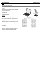
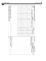
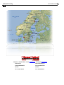
VärmeKabelTeknik Switchpoint heating VELOX Switchpoint heating is designed for connection to 230V ac. The heating elements are of the self‐limiting type which means they are energy efficient as they decrease the heat output when the temperature rises. The elements are double‐insulated and lack protective earthing in order to avoid causing signalling faults if damaged. The elements are flexible and are mounted using clips and protective stainless steel channels 1m long. The elements can be supplied in lengths of up to 18m. The elements are supplied complete with watertight military‐grade quick‐connect devices. Connection is made to adapted 4/2‐way blocks screwed to sleepers and provided with tension‐relieving protective plates. The installation can be supplied complete with controlling and monitoring equipment built to customer design specifications. Switchpoint heating 2 Index VärmeKabelTeknik GENERAL ...................................................................................................................... PAGE General about installation of VELOX Switchpoint heating ........................................................... 2 Compontents ........................................................................................................................... 3‐4 Assembly instructions .............................................................................................................. 5‐6 Assembly instructions for control cabinets .................................................................................. 7 Communication/Supervising ........................................................................................................ 8 Communication/Supervising accessories ............................................................................... 9‐10 Function tests and fault detection .............................................................................................11 Installation protocol ...................................................................................................................12 Own remarks ..............................................................................................................................13 VärmeKabelTeknik .....................................................................................................................14 General remarks about the installation of switchpoint heating Heating element Control system Railway switchpoint heating is installed in order to main‐tain the function of the point mechanism without the need for manual clearing. The VELOX switchpoint heating system can be used with the most existing control systems, provided they supply 230V on the feeder cable to the point heating. The installation involves positioning flexible heating ele‐ ments along the foot of the stock and switch rails. In ex‐ treme cases, double elements will be installed in the sec‐tion of the point blade with the most movement, in order to quickly melt any snow or ice falling off passing trains as a result of vibration. This is because the heaters limit their power output in relation to the temperature of the rail. As a result of its design, the heating element produces a relatively strong starting current, but this can be prevented through the use of soft‐start regulators. VELOX RAILPOINT REGULATOR The point rod pit may also be provided with heating by means of our point rod heaters, which are connected up to extension terminals on the heaters positioned on the stock‐rail. We manufacture custom designed automatic‐control cabi‐nets containing thyristor control devices and soft‐ start regulators, as well as equipment for remote control and logging of energy consumption and temperature, among other data. The heating elements are fixed to the rail using stainless‐steel protective channels. The channels are supplied in lengths of one metre and are available in rigid and flexible designs. The parameters of the regulator can be checked and ad‐ justed from a remote‐connected computer, and logged temperature and current values may, in the same way, be collected and analysed further. Communication is by a fixed telephone connection or via a modem in the auto‐matic‐control cabinet over a mobile link. Heaters and channels are fixed to the rail by means of special clips made of spring steel. Several different types of rail profiles are found in the switchpoints that exist today, and so it is important to state the correct type of rail in order to get the appropriate type of clip. It is important to indicate access to a telecommunication connection and to state the type of feeding available (230/400 or 115/230) and if four or five conductor system. More detailed information can be obtained by our switchpoint heating data sheets. Call +46‐ 301‐418 50 or sen dus a mail ‐ [email protected] ‐ to order these VärmeKabelTeknik Switchpoint heating 3 Components Velox Switchpoint heating element Heating elements are delivered in customized lengths with fitted quick‐connect devices. The elements are tested, insulation measured with high voltage applied and marked with type. Velox installation channels Stainless‐steel channels are supplied in lengths of 1m or 0.5m and as standard channels or slotted channels, for example for clearing the point rod fastening device. Mounting clips for Velox switchpoint heating Normally, the required number of clips are supplied for installing an ordered switchpoint heating system comprising elements, a connection cable and sensors. Do not forget to state the type of rail used in the switch. Velox point rod heater The point rod heater is mounted over the point rod pit. The rod must be kept free from snow and ice and heat is supplied to the critical points on the switch. The point rod heater is supplied in two complete halves, which are easily mounted over the point rod pit. Connection is made to a specially ordered flexible lead connector mounted on the heating element for stock‐ rail. Connection block for switchpoint heating Waterproof rubber connecting blocks moulded in one piece. The blocks are supplied complete with mounting plates for mounting on sleepers and tension‐relieving covering plates. The block has a 4/8‐conductor connection cable moulded into it, length 10m. The blocks are available with 2 or 4 outlets. Switchpoint heating 4 VärmeKabelTeknik Components Velox protective cover To protect the 4‐way block from mechanical damage for example when power brushing rail. Cable joint Is used to connect two cables without use of shrinking tube or filling compound. The cable joint is a dry joint and very easy to use. The cable joint is provided with 2 glands PG29, IP65. max. cable diameter: depending on gland used. This joint can be used for any cable up to a max. diameter of the size a 40mm gland can take. If required smaller glands can be supplied together with reducer from 40mm. Junction box Waterproof junction box. VärmeKabelTeknik Switchpoint heating 5 Assembly instructions Measure the length of the part of the switch which is to be heated. Find out the rail type in question. Decide if an existing control system can be used (230V to the element) or if a new one has to be bought. If a new control system must be bought, find out which functions are required, (type of control, log‐ging, remote control by telephone wire or mobile modem, etc). Send a fax with the above information to us on our fax number: +46‐(0)301‐418 70 or email: [email protected] for handling, quotation and order. When all material has been delivered, check that all components are supplied and that the marking on the heating cable corresponds to the length you ordered. Each heating element has a separate marking enabling you to easily replace a damaged element. Prepare a switch that is in use by brushing the rail foot (where the elements and clips are to be mounted) with a steel brush to obtain good contact. Reel out the element with the connection device furthest away from the tongue tip, and put the cable channel next to the rail. Take out the correct clips Type example 13‐43‐69 for stock‐rail Type example 20‐43‐72 for moving rail Start by mounting the termination end of the element. The first channel has to cover the end termination. Fasten the clips by carefully knocking them in position (see illustration) or by using a mounting tool for rail clips. Mount 4 clips to each metre, spaced out as evenly as possible. NOTE! In applications where point rod heaters are to be mounted, the element for the stock‐rail has been fitted with a conductor joint. Switchpoint heating 6 VärmeKabelTeknik Assembly instructions Fit the next channel tightly against the first one, and it is a good idea to make a clip cover the joint. Continue until the whole element including the connection cable joint is covered. For narrow passages flexible channels are used which can be bent to fit. Here it may also be necessary to use both types of clips to achieve the best possible contact. Repeat the procedure for the other stock‐rail and for the two moving rails. In some extreme cases where the switch is in an exposed position with heavy winds or where large amounts of snow can be expected, an extra element is mounted on the moving rail. This element is mounted on the side facing the stock‐rail. The length of this element can be approximately half the length chosen for the other elements. VärmeKabelTeknik Switchpoint heating 7 Assembly instruction Control cubicle The control cabinet should be mounted as close to the switch as possible to avoid high costs for supplies to the switchpoint heating elements and unnecessarily long sensor cables causing deviations in the values read off. Connections to the elements are made using 8/4 conductors in rubber with separate conductors for each element. Since the control cabinet is fed by a normal Ekki 4 / 5 x 6mm² it is more economical to choose a longer distance for the incoming supply. The control cabinet is supplied internally completed. We supply the connection cable between the cabinet and the element in the standard length of 10m. If the distance exceeds the standard length, an extra connection lead can be jointed in a jointing box supplied by us. Sensors with cables of required length should be ordered. Element cables should be connected to terminal blocks according to the circuit diagram. Sensor cables are connected directly to the sensor card. The cabinet supply cable to the cabinet is connected directly to the line breaker and zero/earth terminal block. Sensors are mounted on the underside of the rail at the tip of the moving rail; the sensor is fixed by tightening the bolt of the special fastening device. The sensor should be placed next to a sleeper and the sensor cable in protective tubing fixed to the side of the sleeper by clips. The control cabinet is constructed around a thyristor control with eight channels (expandable). To the thyristor control belong a control card and one or more eight‐channel sensor cards. A number of accessories can be connected to the sensor cards: Temperature sensor (Thermo element type K) Current transformer for current measuring Moisture sensor etc. Switchpoint heating 8 VärmeKabelTeknik Communication/Supervising Control The elements are controlled by thyristors allowing both routine start and soft start. These functions help minimize the number of fuses on the feeding side. Each card contains eight channels and the card channels can be linked together. Sensors Each sensor card contains eight input ports, and each system can accommodate 30 sensor cards. They can measure current, temperature, voltage, moisture etc. Logging The sensor cards are monitored and logged from a PC. Selected values can be used to control one or more chan‐nels. All values are collected in a log file which can be retrieved from the PC for further examination and analysis of operational statistics, function and power consumption. Communication Monitoring, adjustment of parameters and retrieval of log‐files can be made from any place on earth via a PC/LapTop using fixed or mobile communication. VärmeKabelTeknik Switchpoint heating 9 Communication/Supervising/Accessories Velox Megapoint Velox MegaPoint are available in two basic types: 8‐channel Triac‐based electronical control for alternating voltage up to 400 Volt. A system for control for direct current voltage, DC, up to 650‐900 VDC. Velox Communication system – Leonardo PCBox Leonardo PC BOX is a compact PC for build‐in applications. Are fixed onto DIN‐rail. Weather system Measures temperature, wind, wind‐speed, dew point etc. Switchpoint heating 10 VärmeKabelTeknik Communication/Supervising/Accessories GSM Antenna AU-3S-GSM High performance GPS patch antenna with state‐of‐the‐ art low noise amplifier. Low profile, waterproof, magnetic base quick mounting. WMO2 Modem Series GSM 900 / 1800 / 1900 The Wavecom WMO2 modem is a terminal for fax and data transmission, short message service mobile originated, short mes‐sage service mobile terminated and voice calls. The connectors binded to the body guarantee output and input connections. An extractible holder is used to insert the SIM card (Micro‐SIM type). A LED indicates the operating mode. Siemens Wireless Modem TC35I The new Dual‐Band TC35i is designed for high‐volume applications based on data, voice, SMS or fax. It allows easy integration into a wide range of applications, thanks to its minimized volume and its flexible and easy mounting concept using a ZIF connector and a GSC antenna plug. Thus the TC35i offers the user easy‐to‐ integrate embedded wireless connectivity at low power consumption. As all Siemens modules it is R&TTE and GCF approved. It is also on the list of recommended modules of leading GSM network operators Multi-Modem V3 The MultiModem is a GSM‐modem for industrial use, delivered in a robust aluminium casing for DIN mounting. The unit has 2 inputs which send SMS when triggered. It also has a grounding output for remote control of connected equipment. ‐ Broad voltage range, 9‐28V AC/DC ‐ Full port serial port, works like a regular modem ‐ 2 alarm inputs (4‐28V DC), can send up to 4 SMS ‐ 1 grounding output activated by SMS or phone call ‐ Microprocessor controlled to ensure reliability ‐ Broad field of application ‐ Easy to operate ‐ Individual alarm messages, (max. 160 characters) ‐ Alarm could be sent to a mobile and/or security company ‐ Easy configuration with accompanying PC‐programme. VärmeKabelTeknik Switchpoint heating 11 Function tests and fault detection Checking the function of the switchpoint heating elements The switchpoint heating elements are made out of double‐insulated self‐limiting heating cable with an output power of 100W/m at +10°C ‐ 230V ac ≈ 160 – 170 W/m at –15°C. This type f heating element has a core of dipped fluorethene plastic which has the effect that its resistance increases when the temperature rises. This property allows the elements to automatically save energy when the weather is warm. It also means that, in cold weather there will be an extra amount of heat added. Resistance measuring of self‐limiting elements is not possible as the resistance value reading does not show a value corresponding to the power output. Element tests are to be conducted, with voltage switched on, through measuring the current after about 15 minutes’ operation. The current has then stabilized and can be compared with the value that was measured when the element was installed. It should be noted, however, that if testing is done in the summer, then the current value will be lower than in the winter. If the current is less than 0,2 A, the element should be considered defective. 99 per cent of any voltage leakages or direct short‐ circuits derive from feeder cables or junction boxes. The element plugs can be easily disconnected from the distribution box when measuring. The connection blocks mounted on the track sleeper are of rubber and cast in one piece and so cannot cause a short‐circuit. A connection block’s terminals are fed by separate conductors via an 8‐pole cable cast integral with the block. Current tests can thus be conveniently carried out on each element, off track, in a joint box in the cable duct. The elements are double‐insulated and lack protective earthing. However, the insulation resistance between element and rail may be tested by joining the two pins of the plug to each other and then connecting them jointly to one of the terminals of the insulation tester, the other terminal being connected to the rail. When conducting such tests, you must make sure that you do not cause any signalling errors. Switchpoint heating 12 VärmeKabelTeknik VärmeKabelTeknik Switchpoint heating 13 Notes .................................................................................................................................................................................................... .................................................................................................................................................................................................... .................................................................................................................................................................................................... .................................................................................................................................................................................................... .................................................................................................................................................................................................... .................................................................................................................................................................................................... .................................................................................................................................................................................................... .................................................................................................................................................................................................... .................................................................................................................................................................................................... .................................................................................................................................................................................................... .................................................................................................................................................................................................... .................................................................................................................................................................................................... .................................................................................................................................................................................................... .................................................................................................................................................................................................... .................................................................................................................................................................................................... .................................................................................................................................................................................................... .................................................................................................................................................................................................... .................................................................................................................................................................................................... .................................................................................................................................................................................................... .................................................................................................................................................................................................... .................................................................................................................................................................................................... .................................................................................................................................................................................................... .................................................................................................................................................................................................... .................................................................................................................................................................................................... .................................................................................................................................................................................................... .................................................................................................................................................................................................... .................................................................................................................................................................................................... .................................................................................................................................................................................................... .................................................................................................................................................................................................... .................................................................................................................................................................................................... .................................................................................................................................................................................................... .................................................................................................................................................................................................... .................................................................................................................................................................................................... Switchpoint heating 14 VärmeKabelTeknik Telephone: +46‐301‐418 40 – Email: [email protected] – Homepage: www.vkts.se Industrihuset Södra Hedensbyn 43 S‐430 64 HÄLLINGSJÖ S‐931 91 SKELLEFTEÅ Sweden Sweden Fax: +46‐301‐418 70 Fax: +46‐910‐881 33