1
INVERTER
INVERTER
INVERTER
Plug-in option
FR-A7AL
INSTRUCTION MANUAL
ORIENTATION CONTROL
FR-A7AL
IB(NA)-0600310ENG-B(1208) MEE
Printed in Japan
Specifications subject to change without notice.
INSTRUCTION MANUAL
HEAD OFFICE: TOKYO BUILDING 2-7-3, MARUNOUCHI, CHIYODA-KU, TOKYO 100-8310, JAPAN
B
ENCODER FEEDBACK CONTROL
VECTOR CONTROL
POSITION CONTROL
ENCODER PULSE DIVIDING OUTPUT
PRE-OPERATION INSTRUCTIONS
1
INSTALLATION
2
ORIENTATION CONTROL
3
ENCODER FEEDBACK CONTROL
4
VECTOR CONTROL
5
POSITION CONTROL FUNCTION
6
ENCODER PULSE DIVIDING OUTPUT
7
Thank you for choosing this Mitsubishi Inverter plug-in option.
This Instruction Manual gives handling information and
precautions for use of this equipment. Incorrect handling might
cause an unexpected fault. Before using the equipment, please
read this manual carefully to use the equipment to its optimum.
Please forward this manual to the end user.
This section is specifically about
safety matters
Do not attempt to install, operate, maintain or inspect this
product until you have read through this Instruction Manual and
appended documents carefully and can use the equipment
correctly. Do not use this product until you have a full
knowledge of the equipment, safety information and
instructions.
In this Instruction Manual, the safety instruction levels are
classified into "WARNING" and "CAUTION".
WARNING
CAUTION
Incorrect handling may cause
hazardous conditions, resulting in
death or severe injury.
Incorrect handling may cause
hazardous conditions, resulting in
medium or slight injury, or may
cause only material damage.
CAUTION level may even lead to a serious
The
consequence according to conditions. Both instruction levels
must be followed because these are important to personal
safety.
SAFETY INSTRUCTIONS
1. Electric Shock Prevention
WARNING
• While the inverter power is ON, do not open the front cover or
the wiring cover. Do not run the inverter with the front cover
or the wiring cover removed. Otherwise you may access the
exposed high voltage terminals or the charging part of the
circuitry and get an electric shock.
• Even if power is OFF, do not remove the front cover except for
wiring or periodic inspection. You may accidentally touch the
charged inverter circuits and get an electric shock.
• Before wiring or inspection, power must be switched OFF. To
confirm that, LED indication of the operation panel must be
checked. (It must be OFF.) Any person who is involved in
wiring or inspection shall wait for at least 10 minutes after the
power supply has been switched OFF and check that there
are no residual voltage using a tester or the like. The
capacitor is charged with high voltage for some time after
power OFF, and it is dangerous.
• Any person who is involved in wiring or inspection of this
equipment shall be fully competent to do the work.
• The plug-in option must be installed before wiring. Otherwise,
you may get an electric shock or be injured.
• Do not touch the plug-in option or handle the cables with wet
hands. Otherwise you may get an electric shock.
• Do not subject the cables to scratches, excessive stress,
heavy loads or pinching. Otherwise you may get an electric
shock.
A-1
2. Injury Prevention
3) Usage
WARNING
CAUTION
• The voltage applied to each terminal must be the ones
specified in the Instruction Manual. Otherwise burst, damage,
etc. may occur.
• The cables must be connected to the correct terminals.
Otherwise burst, damage, etc. may occur.
• Polarity must be correct. Otherwise burst, damage, etc. may
occur.
• While power is ON or for some time after power-OFF, do not
touch the inverter as they will be extremely hot. Doing so can
cause burns.
3. Additional Instructions
Also the following points must be noted to prevent an accidental
failure, injury, electric shock, etc.
• Do not modify the equipment.
• Do not perform parts removal which is not instructed in this
manual. Doing so may lead to fault or damage of the inverter.
CAUTION
• When parameter clear or all parameter clear is performed, the
required parameters must be set again before starting operations
because all parameters return to the initial value.
• Static electricity in your body must be discharged before you
touch the product. Otherwise the product may be damaged.
4) Maintenance, inspection and parts replacement
1) Transportation and mounting
CAUTION
• Do not install or operate the plug-in option if it is damaged or
has parts missing.
• Do not stand or rest heavy objects on the product.
• The mounting orientation must be correct.
• Foreign conductive objects must be prevented from entering
the inverter. That includes screws and metal fragments or
other flammable substances such as oil.
2) Trial run
5) Disposal
CAUTION
• This inverter plug-in option must be treated as industrial
waste.
6) General instruction
CAUTION
• Before starting operation, each parameter must be confirmed
and adjusted. A failure to do so may cause some machines to
make unexpected motions.
A-2
CAUTION
• Do not test the equipment with a megger (measure insulation
resistance).
Many of the diagrams and drawings in this Instruction Manual
show the inverter without a cover or partially open for
explanation. Never operate the inverter in this manner. The
cover must be reinstalled and the instructions in the inverter
manual must be followed when operating the inverter.
⎯ CONTENTS ⎯
1
PRE-OPERATION INSTRUCTIONS
1.1
1
Unpacking and Product Confirmation .............................................................................................1
1.1.1
1.1.2
Product confirmation....................................................................................................................................... 1
SERIAL number check ...................................................................................................................................1
1.2
Parts ....................................................................................................................................................2
1.3
Terminal Specifications.....................................................................................................................4
2
2.1
INSTALLATION
7
Pre-Installation Instructions .............................................................................................................7
2.2
Installation Procedure .......................................................................................................................8
2.3
Encoder Specifications/Terminating Resistor Switch..................................................................10
2.4
Wiring................................................................................................................................................12
2.5
Encoder Cable..................................................................................................................................16
2.6
Encoder.............................................................................................................................................18
2.7
Parameters for Encoder ..................................................................................................................20
3
ORIENTATION CONTROL
22
3.1
Wiring Example ................................................................................................................................22
3.2
Terminals ..........................................................................................................................................24
3.3
Orientation Control Parameter List ................................................................................................27
3.4
Machine End Orientation Control...................................................................................................28
I
3.5
4
Specifications...................................................................................................................................29
ENCODER FEEDBACK CONTROL
4.1
30
Wiring Example ................................................................................................................................30
4.2
Terminals ..........................................................................................................................................32
4.3
Encoder Feedback Control Parameter List ...................................................................................32
5
VECTOR CONTROL
5.1
33
Wiring Example ................................................................................................................................34
5.2
Terminals ..........................................................................................................................................38
5.3
Vector Control Extended Parameter List.......................................................................................39
5.4
Pulse Train Torque Command........................................................................................................43
5.4.1
5.4.2
5.5
6
Parameter list ............................................................................................................................................... 43
Pulse train torque command......................................................................................................................... 43
Specifications...................................................................................................................................44
POSITION CONTROL FUNCTION
6.1
45
Position Control by Vector Control................................................................................................45
6.1.1
Position control ............................................................................................................................................. 45
6.2
Wiring Example ................................................................................................................................48
6.3
Terminals ..........................................................................................................................................50
6.4
Operation ..........................................................................................................................................51
6.4.1
II
Operation by position command using pulse train........................................................................................ 53
6.4.2
6.4.3
Initial setting.................................................................................................................................................. 54
Setting the electronic gear (Pr. 420, Pr. 421, Pr. 424).................................................................................. 54
6.5
Pulse Input Type ..............................................................................................................................60
6.6
Interface of the Positioning Module and Inverter .........................................................................62
6.7
Extended Function Parameter List.................................................................................................63
6.8
Parameter Setting and Details ........................................................................................................64
6.8.1
6.8.2
6.8.3
6.8.4
6.8.5
6.8.6
6.9
7
Block diagram............................................................................................................................................... 64
Selection of control method (Pr. 800) ........................................................................................................... 64
Position control ............................................................................................................................................. 67
Gain adjustment of position control (Pr. 422, Pr. 423, Pr. 425) .................................................................... 68
Selection of clear signal (Pr. 429, CR signal) ................................................................................................ 71
Troubleshooting............................................................................................................................................ 72
Specifications...................................................................................................................................74
ENCODER PULSE DIVIDING OUTPUT
75
7.1
Wiring Example ................................................................................................................................75
7.2
Terminals ..........................................................................................................................................77
7.3
Encoder.............................................................................................................................................78
III
1
PRE-OPERATION INSTRUCTIONS
1.1
Unpacking and Product Confirmation
Take the plug-in option out of the package, check the product name, and confirm that the product is as you
ordered and intact.
This product is a plug-in option unit dedicated for the FR-A700 series.
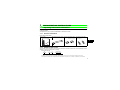
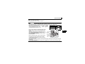
1.1.1
Product confirmation
Check the enclosed items.
Plug-in option ................... 1 FR-A7NS connection cable Mounting screws (M3×6mm) Hex-head screw for option
................ 1 (Refer to page 9) ............... 4 (Refer to page 8) mounting (5.5mm) ..............2
(Refer to page 8)
1
5.5mm
5.5mm
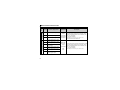
1.1.2
SERIAL number check
The FR-A7AL can be used with the FR-A700 series assembled in and after October 2007. Check the SERIAL number
indicated on the inverter rating plate or package.
Rating plate example
7
X
Symbol
Year Month
{{{{{{
Control number
SERIAL number
The SERIAL consists of one symbol, two characters indicating production year and month, and six characters indicating control number.
The last digit of the production year is indicated as the Year, and the Month is indicated by 1 to 9, X (October), Y (November), or Z (December).
1
PRE-OPERATION INSTRUCTIONS
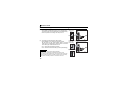
1.2
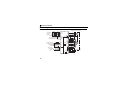
Parts
TE3 Terminal block
Front view
Mounting
hole
Rear view
FR-A7AL
SW3
TE2 Terminal
block
1
2
O
N
Mounting
hole
SW1
Mounting
hole
CON2 connector
Connector for the FRA7NS (SSCNET III)
connection
Mounting
hole
O
N
FR-A7AL
SW2
TE1 Terminal
block
1
2
3
4
Mounting
hole
Mounting
hole
Connector
Connect to the inverter
option connector. (Refer to page 8.)
Terminating resistor selection
switch (SW2)
Switch ON/OFF of the internal
terminating resistor.(Refer to page 10.)
Switch for manufacturer
setting (SW3)
Do not change from initiallyset status (1, 2:OFF
).
Encoder specification selection switch (SW1)
Used to change the specification of encoder
(differential line driver/complementary).(Refer to page 10.)
2
1
2
O
N
PRE-OPERATION INSTRUCTIONS
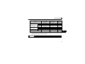
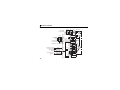
Terminal layout
FR-A7AL
SD
SD
*
PA
FPA
PAR
FPAR
PB
FPB
PBR
FPBR
PZ
FPZ
PZR
FPZR
PG
FPA2
PG
FPB2
SD
FPZ2
SD
SD
PGP
SD
SD
PP
VDD
SD
PGN
VDD
NP
RDY
OPC
OP
SD
CR
TST1
TST2
1
* Terminals TST1 and TST2 are not used. Do not connect anything to these. Accidental connection will damage the option.
3
PRE-OPERATION INSTRUCTIONS
Position control function
Function
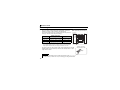
1.3
Terminal Specifications
Terminal
Terminal (Signal) Name Specification
Symbol
PGP
PP
Forward rotation pulse
train
PGN
NP
Reverse rotation pulse
train
CR
OPC
SD
VDD
RDY
OP
4
Clear
Open collector power
input
Contact input common
Driver power supply
Preparation ready signal
Encoder Z-phase output
Description
Forward rotation pulse
For open collector, connect
train input terminal.
terminal VDD and OPC, then
Input pulse train from the input pulses across terminal
Open collector/
pulse generating unit.
PP-SD and NP-SD.
differential line
For differential line driver, open
Reverse rotation pulse
driver
terminal OPC, then input pulse
train input terminal.
Input pulse train from the across terminal PP-PGP and
NP-PGN.
pulse generating unit.
Shorting terminal CR-SD clears counter at the falling
—
edge.
When inputting pulse by open collector method, connect
24VDC
this terminal to terminal VDD (24V power supply)
—
24VDC
—
Contact input common terminal. Do not earth (ground).
Driver power supply terminal for interface.
When servo ON and ready to drive, the signal is output.
Open collector
output
permissible load Outputs one pulse per motor revolution.
24VDC,
max. 50mA
Function
PRE-OPERATION INSTRUCTIONS
Terminal
Terminal (Signal) Name Specification
Symbol
PA
PAR
Encoder pulse input
PB
PBR
PZ
PZR
PG
SD
Description
Encoder A-phase signal
input
Encoder A-phase inverse
signal input
Encoder B-phase signal
Differential line
input
driver/
A-, B- and Z-phase signals are input from the encoder.
Encoder B-phase inverse
complementary
signal input
Encoder Z-phase signal
input
Encoder Z-phase inverse
signal input
Power supply (positive
Input terminal for the encoder power supply.
side) input
Connect the external power supply (5V, 12V, 15V, 24V)
and the encoder power cable. When the encoder output
is the differential line driver type, only 5V can be input.
Make sure the voltage of the external power supply is the
Power ground
same as the encoder output voltage. (Check the encoder
specification.)
CAUTION
When the input power supply voltage to the encoder and its output voltage differ, the signal loss detection
(E.ECT) may occur.
5
1
Open collector
Terminal
Symbol
FPA2
FPB2
FPZ2
FPA
Differential line driver
Encoder pulse division output
Function
PRE-OPERATION INSTRUCTIONS
FPAR
FPB
FPBR
FPZ
FPZR
6
Terminal (Signal) Name
Specification
Description
Outputs the A-phase, B-phase and Z-phase (origin
Encoder A-phase signal output Open collector
and mark pulse) signals from the encoder. The Aoutput
phase and B-phase signals can be divided by the
Encoder B-phase signal output
ratio (1/n) and output.
Permissible
n=1 to 32767 (integer).
load 24VDC
Encoder Z-phase signal output max. 50mA Set using Pr.413 Encoder pulse division ratio.
Common terminal is terminal SD.
Encoder differential A-phase
signal output
Encoder differential A-phase
Differential
inverse signal output
Outputs the A-phase, B-phase and Z-phase (origin
line driver
Encoder differential B-phase
and mark pulse) signals from the encoder. The Aoutput
signal output
phase and B-phase signals can be divided by the
ratio (1/n) and output.
Encoder differential B-phase
Permissible
n=1 to 32767 (integer).
inverse signal output
load
Set using Pr.413 Encoder pulse division ratio.
Encoder differential Z-phase
0.1A
signal output
Encoder differential Z-phase
inverse signal output
2
INSTALLATION
2.1
Pre-Installation Instructions
Make sure that the input power of the inverter is off.
CAUTION
Do not mount or remove the plug-in option while the power is being input. Otherwise, the
inverter and plug-in option may be damaged.
Static electricity in your body must be discharged before you touch the product. Otherwise the
product may be damaged.
2
7
INSTALLATION
2.2
Installation Procedure
1)
1)
Remove the inverter front cover.
2)
This option can be fitted to either option
connector 2 or 3. (The left diagram shows
that the option is fitted to connector 3.)
Mount the hex-head screw for option
mounting into the inverter screw hole (on
earth plate). (size 5.5mm, tightening
torque 0.56N ⋅ m to 0.75N ⋅ m)
3)
Securely fit the connector of the plug-in
option to the inverter connector along the
guides. This option occupies space
equivalent to two option units.
4)
Fix four places on both right and left sides
of the plug-in option unit to the inverter
securely with the accessory mounting
screws. (Tightening torque: 0.33N⋅m to
0.40N⋅m) If the screw holes do not line up,
the connector may not have been plugged
securely. Check for loose plugging.
Screw hole for
option mounting
Inverter side
option
connector 3
3)
Screw hole for
option mounting
(on earth plate)
2)
Hex-head screw
for option mounting
4) Mounting
screws
REMARKS
Remove the plug-in option after removing four screws on both left and right sides.
(When the plug-in option is mounted in the connector 3, it is easier to remove the plug-in option after removing the
control circuit terminal block.)
8
INSTALLATION
There are three connection connectors for the plug-in option at the inverter and they are called CON. 1,
CON. 2, and CON. 3 from the top.
The FR-A7AL can be fitted to CON. 2 or CON. 3.
CAUTION
y The FR-A7AL requires space equivalent to two option units. Only one option can be used at the time. For
other option units, mount it to the option CON. 1 or CON. 3. It cannot be connected to the option CON. 2.
y When both the FR-A7AL and FR-A7AP are fitted, the FR-A7AP function will be made invalid.
y When the inverter cannot recognize that the option is mounted
Mounting Position
Fault Display
due to improper installation, etc., "
to
" (option
alarm) are displayed. The errors shown differ according to the
mounting positions (Connector. 1, 2, 3).
Connector 1
Connector 2
Connector 3
y When using the FR-A7AL and FR-A7NS together, fit the
•
•
•
FR-A7AL at option CON. 2 and the FR-A7NS at option
CON. 3.
FR-A7AL
After fitting both the FR-A7AL and FR-A7NS, connect
each external connector with a connection cable (refer to
External
page 1) packed with the FR-A7AL.
connector
(Do not use the FR-A7AP connection cable enclosed
with the FR-A7NS.)
FR-A7NS
FR-A7NS
When mounting/removing an option, hold the sides of
connection
the option. Do not press on the parts on the option
cable
circuit board. Stress applied to the parts by pressing,
etc. may cause a failure.
Take caution not to drop a hex-head screw for option mounting or mounting screw during option mounting
and removal.
Pull the option straight out when removing. Pressure applied to the connector and to the option circuit
board may break the option.
2
9
INSTALLATION
2.3
Encoder Specifications/Terminating Resistor Switch
(1) Encoder specification selection switch (SW1)
Select either the differential line driver or complementary.
The switch is set to the complementary in the initial setting.
Switch its position according to the output circuit.
Complementary
(initial setting)
FR-A7AL
Differential line driver
SW1
O
N
1
2
3
4
O
N
SW2
1
2
3
4
(2) Terminating resistor selection switch (SW2)
Internal terminating
Select ON/OFF of the internal terminating resistor.
resistor-OFF
Set the switch to OFF (initial status) when an encoder (initial setting)
output type is complementary. Set the switch to ON when
an encoder type is differential line driver.
ON : With internal terminating resistor
OFF : Without internal terminating resistor (initial setting)
y Set all switches to the same setting (ON/OFF).
y If the encoder output type is differential line driver, set the
terminating resistor switch to the "OFF" position when sharing the
same encoder with other unit (CNC (computer numerical control),
etc) and a terminating resistor is connected to other unit.
10
Internal terminating
resistor-ON
SW1
SW2
REMARKS
FR-A7AL
INSTALLATION
(3) Motor used and switch setting
Mitsubishi standard motor
with encoder
Mitsubishi high-efficiency
motor with encoder
Power
Specifications
Encoder Specification
Switch (SW1)
Terminating Resistor
Switch (SW2)
SF-JR
SF-HR
Differential
Differential
ON
ON
5V
5V
Others
*1
*1
*1
Motor
*2
SF-JRCA
Differential
ON
5V
SF-HRCA
Differential
ON
5V
Others
*1
*1
*1
Vector dedicated motor
SF-V5RU
Complementary
OFF
12V
Other manufacturer’s motor with
*1
*1
*1
encoder
*1 Set according to the motor (encoder) used.
*2 Choose a power supply (5V/12V/15V/24V) for encoder according to the encoder. When the encoder output
is the differential line driver type, only 5V can be input.
Mitsubishi constant-torque
motor with encoder
CAUTION
y Switch "SW3" is for manufacturer setting. Do not change this setting.
11
2
INSTALLATION
2.4
(1)
Wiring
Use shielded twisted pair cables (0.2mm2 or larger) to connect the
FR-A7AL. Cables to terminals PG and SD should be connected in
parallel or be larger in size according to the cable length.
To protect the cables from noise, run them away from any source of
noise (e.g. the main circuit and power voltage).
Wiring Length
Parallel Connection
(Cable gauge 0.2mm2)
Larger-size Cable
Within 10m
At least two cables in parallel
0.4mm2 or larger
Within 20m
At least four cables in parallel
0.75mm2 or larger
Within 100m*
At least six cables in parallel
1.25mm2 or larger
Example of parallel connection
with two cables
(with complementary encoder output)
FR-A700
(FR-A7AL)
PLG
PA
PAR
PB
PBR
PZ
PZR
A
B
C
D
F
G
PG
SD
S
R
* When encoder type is differential line driver and a wiring length is 30m or more
Use a power supply slightly higher than 5V (approximately 5.5V) in addition to 6
or more parallel cables of 0.2mm2 or cables of 1.25mm2 or more. Note that the
voltage applied should be within power supply specifications of encoder.
To reduce noise of the encoder cable, earth (ground) the encoder
shielded cable to the enclosure (as near as the inverter) with a P clip or
U clip made of metal.
2mm 2
Earthing (grounding)
example using a P clip
Encoder cable
Shield
P clip
REMARKS
y For details of the dedicated encoder cable (FR-JCBL/FR-V7CBL), refer to page 16.
y The FR-V7CBL is provided with a P clip for earthing (grounding) shielded cable.
12
INSTALLATION
(2) Connection with CNC (computer numerical control)
When one position detector is shared between the FR-A7AL and
CNC, its output signal should be connected as shown at the right
figure. In this case, the wiring length between the FR-A7AL and
CNC should be as short as possible (within 5m).
Inverter
(FR-A7AL)
Position detector
encoder
Maximum 5m
(two parallel cables)
(3) Strip sheath of a shielded twisted pair cable and untwist its wires for
wiring.
Also, perform terminal treatment of the shield to ensure that it will not
make contact with the conductive area.
CNC
Shield
(perform protective treatment)
Sheath
Shielded twisted
pair cable
2
Strip off the sheath for the below length. If the length of the sheath peeled is too long, a short circuit
may occur with neighboring wires. If the length is too short, wires might come off.
Wire the stripped cable after twisting it to prevent it from becoming loose.
(Do not solder it.)
Cable stripping length
5mm
Use a blade type terminal as required.
13
INSTALLATION
REMARKS
• Information on blade terminals
Commercially available product examples (as of February 2012)
Terminal
Screw Size
Wire Size
(mm2)
M2
0.3, 0.5
Blade Terminal Model
With insulation
Without
sleeve
insulation sleeve
AI 0,5-6WH
A 0,5-6
Maker
Crimping Tool
Name
Phoenix Contact Co.,Ltd.
CRIMPFOX 6
Insert wires to a blade terminal, and check that the wires come out for about 0 to 0.5 mm from a sleeve.
Check the condition of the blade terminal after crimping. Do not use a blade terminal of which the crimping is
inappropriate, or the face is damaged.
ll
he
Unstranded
wires
ire
W
S
e
ev
m
.5m
o0
t
0
e
Sl
Damaged
Wires are not inserted
into the shell
Crumpled tip
(4) Loosen the terminal screw and insert the cable into the terminal.
Screw Size
Tightening Torque
Cable Size
Screwdriver
M2
0.22N ⋅ m to 0.25N ⋅ m
0.3mm2 to 0.75mm2
Small flathead screwdriver
(Tip thickness: 0.4mm /tip width: 2.5mm)
CAUTION
Undertightening can cause cable disconnection or malfunction. Overtightening can cause a short circuit or
malfunction due to damage to the screw or unit.
14
INSTALLATION
(5) For wiring of the inverter which has one front cover, remove a hook of the front cover and use the
space become available.
For wiring of the inverter which has front covers 1 and 2, use the space on the left side of the
control circuit terminal block.
Front cover
Cut off
with a
nipper,
etc.
Cut off a hook on the inverter
front cover side surface.
(Cut off so that no portion is left.)
Front cover 1
Front cover 2
Control circuit
terminal block
Inverter which has front covers 1 and 2
Inverter which has one front cover
..
.
REMARKS
y When the hook of the inverter front cover is cut off for wiring, the protective structure (JEM1030) changes to open type (IP00).
CAUTION
Do not use empty terminals as junction terminals because they are used in the option unit. If
they are used as the junction terminals, the option unit may be damaged.
When performing wiring using the space between the inverter front cover and control circuit
terminal block, take caution not to subject the cable to stress.
During wiring, do not leave wire offcuts in the inverter. They may cause a fault, failure or
malfunction.
15
2
INSTALLATION
2.5
Encoder Cable
SF-JR/HR/JRCA/HRCA with Encoder
SF-V5RU, SF-THY
D/MS3057-12A
Encoder side
D/MS3057-12A
connector
Inverter side
Approx. 140
60
FR-A700
(FR-A7AL)
Earthing (grounding)
cable
60mm
L
D/MS3106B20-29S
Model
Length L (m)
FR-JCBL5
FR-JCBL15
FR-JCBL30
5
15
30
C
R
A
N
B
P
PG
SD
H
K
2mm2
Positioning keyway
A B
M
N
C
L
P D
T
K
E
S
R
J
H G F
D/MS3106B20-29S
L
y A P clip for earthing
(grounding) a shielded
cable is provided.
FR-A700
(FR-A7AL)
Encoder
PA
PAR
PB
PBR
PZ
PZR
11mm
*
F-DPEVSB 12P 0.2mm2
Earthing (grounding) F-DPEVSB 12P 0.2mm2
cable
Model
Length L (m)
FR-V7CBL5
FR-V7CBL15
FR-V7CBL30
5
15
30
Encoder
PA
PAR
PB
PBR
PZ
PZR
A
B
C
D
F
G
PG
SD
S
R
D/MS3106B20-29S
(As viewed from wiring side)
Positioning keyway
M A B
N C
P D
T
K
E
S R
J
H G F
D/MS3106B20-29S
(As viewed from wiring side)
L
2mm2
* As the terminal block of the FR-A7AL is an insertion type, cables need to be modified. (Refer to page 13)
16
INSTALLATION
Connection terminal compatibility table
Motor
Encoder cable
FR-A7AL terminal
SF-V5RU, SF-THY
FR-V7CBL
SF-JR/HR/JRCA/HRCA (with encoder)
FR-JCBL
PA
PA
PAR
Do not connect anything.
PA
PAR
PB
PB
PB
PBR
Do not connect anything.
PBR
PZ
PZ
PZ
PZR
Do not connect anything.
PZR
PG
PG
5E
SD
SD
AG2
2
17
INSTALLATION
2.6
(1)
Encoder
Position detection (pulse encoder)
Output pulse specifications
Differential line driver
Complementary
A/A signal 1000P/R to 4096P/R
B/B signal 1000P/R to 4096P/R
Z/Z signal 1P/R
P
a b c d
H
A
L
A
B
B
Z
Z
A signal 1000P/R to 4096P/R
B signal 1000P/R to 4096P/R
Z signal 1P/R
P
a b c d
Position detector
encoder
A
A
B
Z
When rotation is clockwise
as viewed from the shaft
end (A) of the encoder.
a, b, c, d should be (1/4
1/8)P
CAUTION
y When orientation control, encoder feedback control, and vector control are used, an encoder is shared.
Use the encoder with a number of pulses of 1000 to 4096P/R.
y Couple the encoder with the motor shaft or with the shaft that stops the main shaft at the specified position.
Couple it with the speed ratio of 1:1 and without any mechanical looseness.
y To ensure correct operation, the encoder must be set in the proper rotation direction and the A and B
phases connected correctly.
18
INSTALLATION
(2) Power supply
Choose a power supply for encoder (5V/12V/15V/24V) according to the encoder specifications. When
the encoder output is the differential line driver type, only 5V can be input. Make sure the voltage of the
external power supply is the same as the encoder output voltage.
Use the same power supply for the encoder during orientation control, encoder feedback control, and
vector control.
y Specifications of the encoders equipped in motors and vector-control dedicated motors
Item
Resolution
Power supply voltage
Current consumption
Output signal form
Output circuit
Output voltage
Encoder for SF-JR/HR/JRCA/HRCA
Encoder for SF-V5RU and SF-THY
1024 pulse/rev
5VDC ±10%
150mA
2048 pulse/rev
12VDC ± 10%
150mA
A, B phases (90° phase shift)
Z-phase: 1 pulse/rev
Differential line driver 74LS113 equivalent
A, B phases (90° phase shift)
Z-phase: 1 pulse/rev
Complementary
"H" level (-3V of the power supply voltage
for encoder) or more
"L" level 3V or less
"H" level 2.4V or more
"L" level 0.5V or less
CAUTION
When the input power supply voltage to the encoder and its output voltage differ, the signal loss detection
(E.ECT) may occur.
19
2
INSTALLATION
2.7
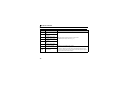
Parameters for Encoder
y Parameter setting for encoder used with motor
Parameter
Number
Name
Initial Setting
Value Range
Description
CW
0
359
Encoder rotation
direction
A
Encoder
1
CCW
A
1
Encoder
369
20
Number of
encoder pulses
1024
0 to
4096
Set the rotation
Forward rotation is clockwise
direction
rotation when viewed from A.
Forward rotation is
counterclockwise
rotation when viewed from A.
according to the
motor
specification.
Set the number of pulses of the encoder.
Set the number of pulses before multiplied by four.
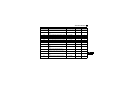
INSTALLATION
Pr. 359 Encoder rotation
Pr. 369 Number of encoder
direction
pulses
SF-JR
SF-JR 4P 1.5kW or less
SF-HR
Others
SF-JRCA 4P
SF-HRCA
Others
SF-V5RU (1500r/min series)
SF-V5RU (other than 1500r/min series)
SF-THY
1
1
1
*
1
1
*
1
1
1
1024
1024
1024
*
1024
1024
*
2048
2048
2048
—
*
*
—
*
*
Motor Name
Mitsubishi standard motor
Mitsubishi constant-torque
motor
Vector dedicated motor
Other manufacturer's
standard motor
Other manufacturer's
constant-torque motor
Values in
2
are initial values.
* Set this parameter according to the motor used.
21
3
ORIENTATION CONTROL
This function is used with a position detector (encoder) installed to the spindle of a machine tool, etc. to
allow a rotation shaft to be stopped at the specified position (oriented).
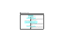
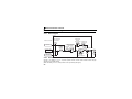
3.1
Wiring Example
MCCB
Threephase
AC power
supply
Forward rotation start
Reverse rotation start
Orientation command
Contact input common
MC
SF-JR motor with encoder
Inverter
U
V
W
R/L1
S/L2
T/L3
STF
STR
X22*3
SD
ORA*4
ORM
FR-A7AL
PA
U
V
W
E
R
PB
A
PBR
N
PZ
PZR
B
*4
SE
SD
PG
FR-A7AX
*10 Differential SD
X15
PG
X14
SD
X1
*8
Terminating
X0
*7 resistor
DY
ON
OFF
Inverter
OCR
A
B
C
U
V
W
2W1kΩ
G1
SD
G2
Encoder
A
PAR
B
H
PB
C
K
PBR
D
(-)
FAN
IM
Earth (Ground)
*5
Complementary PZ
F
PZR
G
Differential PG
S
SD
R
*6
(+)
SF-V5RU
U
V
W
E
PC
External
thermal relay
CS(OH)
input *11
5VDC power
supply*9
Thermal
relay
protector
*2
Encoder
*5
PG
SD
Terminating *8
*7 resistor
OFF
22
MC
Threephase
AC power
supply
FR-A7AL PA
P
Complementary
MCCB
*1
IM
Earth (Ground)
C *2
PAR
For complementary type (SF-V5RU)
ON
*6
(+)
(-)
12VDC
power
supply *9
ORIENTATION CONTROL
*1
*2
*3
*4
*5
*6
*7
*8
*9
*10
*11
For the fan of the 7.5kW or lower dedicated motor, the power supply is single phase (200V/50Hz, 200 to 230V/60Hz).
The pin number differs according to the encoder used.
Assign the function using Pr. 178 to Pr. 189 (input terminal function selection).
Refer to the Instruction Manual of the Inverter for details of Pr. 178 to Pr. 189 (input terminal function selection).
Assign the function using Pr. 190 to Pr. 196 (output terminal function selection).
Refer to the Instruction Manual of the Inverter for details of Pr. 190 to Pr. 196 (output terminal function selection).
The encoder should be coupled on the same axis with the motor shaft without any mechanical looseness.
Speed ratio should be 1:1.
Earth (Ground) the shielded cable of the encoder cable to the enclosure with a P clip, etc. (Refer to page 12 )
For the differential line driver, set the terminating resistor selection switch to on position. (Refer to page 10)
Note that the terminating resistor switch should be set to off position (initial status) when sharing the same encoder with other unit
(NC, etc) and a terminating resistor is connected to other unit.
For the complementary, set the terminating resistor switch to off position (initial status).
Refer to page 17 for terminal compatibility of the FR-JCBL, FR-V7CBL and FR-A7AL.
A separate power supply of 5V/12V/15V/24V is necessary according to the encoder power specification. When the encoder
output is the differential line driver type, only 5V can be input. Make the voltage of the external power supply the same as the
encoder output voltage, and connect the external power supply between PG and SD.
When performing encoder feedback control and vector control together, an encoder and power supply can be shared.
When a stop position command is input from outside, a plug-in option FR-A7AX is necessary.
Refer to the Instruction Manual of the Inverter for details of external stop position command.
Assign OH (external thermal input) signal to the terminal CS. (Set "7" in Pr. 186.)
CS(OH)
Connect a 2W1kΩ resistor between the terminal PC and CS (CH).
Install the resistor pushing it against the bottom part of the terminal block so as to
PC
avoid a contact with other cables.
Control circuit
terminal block
Resistor (2W1kΩ)
23
3
ORIENTATION CONTROL
3.2
Terminals
(1) Option FR-A7AL terminal
Terminal
Symbol
PA
PAR
PB
PBR
PZ
PZR
PG
SD
24
Terminal Name
Encoder A-phase signal
input
Encoder A-phase inverse
signal input
Encoder B-phase signal
input
Encoder B-phase inverse
signal input
Encoder Z-phase signal
input
Encoder Z-phase inverse
signal input
Power supply (positive
side) input
Power ground
Description
A-, B- and Z-phase signals are input from the encoder.
(For details of pulse signal, refer to page 18.)
Input power for the encoder power supply.
Connect the external power supply (5V, 12V, 15V, 24V) and the power
cable from encoder. When the encoder output is the differential line
driver type, only 5V can be input. Make sure the voltage of the external
power supply is the same as the encoder output voltage.
ORIENTATION CONTROL
(2) Option FR-A7AX terminal
Terminal
Symbol
Terminal Name
X0 to X15
Digital signal
input
DY
Data read
timing
input signal
SD
(inverter)
PC
(inverter)
Common
(sink)
External
transistor
common
(source)
Description
Input the digital signal at the relay contact or open collector terminal.
Using Pr. 360 , speed or position command is selected as the command signal
entered.
Used when a digital signal read timing signal is necessary. Data is read only
during the DY signal is on.
By switching the DY signal off, the X0 to X15 data before signal-off can be
retained.
Common terminal for digital and data read timing signals.
Use terminal SD of the inverter.
When connecting the transistor output (open collector output), such as a
programmable controller, connect the external power common (+) to this
terminal to prevent a fault occurring due to leakage current.
3
25
ORIENTATION CONTROL
(3) Inverter terminal
Input
Terminal
(Signal)
X22
SD
Output
ORA
Terminal
(Signal) Name
Orientation
command
input signal
Contact input
common
Orientation
completion
signal output
signal
Orientation fault
ORM signal output
signal
SE
Open collector
output common
Description
Used to enter an orientation signal for orientation.
For the terminal used for X22 signal input, set "22" in any of Pr. 178 to Pr. 189 to
assign the function. *
Common terminal for the orientation signal.
Switched low if the orientation has stopped within the in-position zone while the
start and orientation signals are input.
For the terminal used for the ORA signal output, assign the function by setting
"27 (positive logic) or 127 (negative logic)" in any of Pr. 190 to Pr. 196. *
Switched low if the orientation has not stopped within the in-position zone while
the start and orientation signals are input.
For the terminal used for the ORM signal output, assign the function by setting
"28 (positive logic) or 128 (negative logic)" in any of Pr. 190 to Pr. 196. *
Common terminal for the ORA and ORM open collector output terminals.
* Refer to the Instruction Manual of the Inverter for details of Pr. 178 to Pr. 189 (input terminal function selection) and Pr. 190 to Pr. 196 (output
terminal function selection).
26
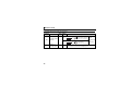
ORIENTATION CONTROL
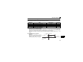
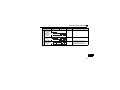
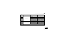
3.3
Orientation Control Parameter List
The following parameters for orientation control are available when used with the FR-A7AL.
Refer to the inverter manual for details of parameter.
Parameter Number
Name
Setting Range
Increments
Initial Value
350
351
352
353
354
355
356
357
358
359
360
361
362
363
364
365
366
369
376
393
396
397
398
399
829
Stop position command selection
Orientation speed
Creep speed
Creep switchover position
Position loop switchover position
DC injection brake start position
Internal stop position command
Orientation in-position zone
Servo torque selection
Encoder rotation direction
16 bit data selection
Position shift
Orientation position loop gain
Completion signal output delay time
Encoder stop check time
Orientation limit
Recheck time
Number of encoder pulses
Encoder signal loss detection enable/disable selection
Orientation selection
Orientation speed gain (P term)
Orientation speed integral time
Orientation speed gain (D term)
Orientation deceleration ratio
Number of machine end encoder pulses
0, 1, 9999
0 to 30Hz
0 to 10Hz
0 to 16383 *
0 to 8191
0 to 255
0 to 16383 *
0 to 255
0 to 13
0, 1
0 to 127
0 to 16383 *
0.1 to 100
0 to 5s
0 to 5s
0 to 60s, 9999
0 to 5s, 9999
0 to 4096
0, 1
0, 1, 2
0 to 1000
0 to 20s
0 to 100
0 to 1000
0 to 4096, 9999
1
0.01Hz
0.01Hz
1
1
1
1
1
1
1
1
1
0.1
0.1s
0.1s
1s
0.1s
1
1
1
1
0.001
0.1
1
1
9999
2Hz
0.5Hz
511
96
5
0
5
1
1
0
0
1
0.5s
0.5s
9999
9999
1024
0
0
60
0.333
1
20
9999
3
* When an operation panel (FR-DU07) is used, the maximum setting is 9999. When a parameter unit is used, up to the maximum value
within the setting range can be set.
27
ORIENTATION CONTROL
3.4
Machine End Orientation Control
Parameter
Number
829
Name
Number of machine
end encoder pulses
Initial
Value
Setting
Range
9999
Set the number of pulses of the encoder connected
0 to 4096 to the machine end.
Set the number of pulses before multiplied by four.
9999
Machine end orientation cannot be performed.
Description
To execute encoder feedback control/vector control and machine end orientation control simultaneously by
using the machine end encoder, set the number of machine end encoder pulses in Pr. 829 Number of
machine end encoder pulses.
Orientation control becomes possible for the machine end encoder.
•Setting example
When the number of machine end encoder pulses is 4000 pulses and the gear ratio of the motor end and
the machine end is 4:1 (for every four revolutions of the motor, the machine makes one revolution)
Number of encoder pulses equivalent to the number of motor end pulses = 4000 × 1/4 = 1000
Therefore, set Pr. 369 = "1000" and Pr. 829 = "4000" (number of machine end encoder pulses).
REMARKS
Refer to the Instruction Manual of the Inverter for details on the encoder feedback control, vector control and orientation
control.
28
ORIENTATION CONTROL
3.5
Specifications
Repeated positioning
accuracy
Permissible speed
Function
Holding force after
positioning
Input signal
(contact input)
±1.5°
Depends on the load torque, moment of inertia of the load or orientation, creep speed,
position loop switching position, etc.
Encoder-mounted shaft speed (6000r/min with 2048-pulse encoder)
The motor and encoder-mounted shaft must be coupled directly or via a belt without any slip.
It can not be applied to a gear change type.
Orientation, creep speed setting, stop position command selection, DC injection brake start
position setting, creep speed and position loop switch position setting, position shift,
orientation in-position, position pulse monitor, etc.
Under V/F control, Advanced magnetic flux vector control...without servo lock function
Under vector control...with servo lock function
Orientation command, forward and reverse rotation commands, stop position command
(open collector signal input (complementary) is enabled)
Binary signal of maximum 16 bits (when used with the FR-A7AX)
Output signal
Orientation complete signal, orientation fault signal
(open collector output)
3
29
4
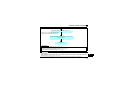
ENCODER FEEDBACK CONTROL
When the FR-A7AL is mounted in the FR-A700 series, encoder feedback control is enabled during V/F
control and Advanced magnetic flux vector control.
This function controls the inverter output frequency so that the motor speed is constant to the load variation
by detecting the motor speed with the speed detector (encoder) to feed it back to the inverter.
4.1
Wiring Example
MCCB
Three-phase
AC power
supply
Forward rotation start
Reverse rotation start
Contact input common
Frequency setting
potentiometer
MC
Inverter
R/L1
S/L2
T/L3
U
V
W
STF
STR
FR-A7AL
PA
PAR
SD
10
Differential
R
PB
A
PBR
N
PG
H
SD
K
Complementary
2
5
SF-JR motor with encoder
U
V
IM
W
E
Earth
(Ground)
*1
C
Encoder
*2
PG
SD
*5
Terminating
*4 resistor
OFF
30
ON
*3
(+)
(-) 5VDC power supply *6
ENCODER FEEDBACK CONTROL
*1
*2
*3
*4
*5
*6
The pin number differs according to the encoder used.
The encoder should be coupled on the same axis with the motor shaft without any mechanical looseness. Speed ratio should be
1:1.
Earth (Ground) the shielded cable of the encoder cable to the enclosure with a P clip, etc. (Refer to page 12)
For the differential line driver, set the terminating resistor selection switch to ON position. (Refer to page 10)
Note that the terminating resistor switch should be set to OFF position (initial status) when sharing the same encoder with other
unit (CNC, etc.) and a terminating resistor is connected to other unit.
For the complementary, set the terminating resistor selection switch to OFF position (initial status).
Refer to page 17 for terminal compatibility of the FR-JCBL, FR-V7CBL and FR-A7AL.
A separate power supply of 5V/12V/15V/24V is necessary according to the encoder power specification. When the encoder
output is the differential line driver type, only 5V can be input. Make the voltage of the external power supply the same as the
encoder output voltage, and connect the external power supply between PG and SD.
When performing orientation control together, an encoder and power supply can be shared.
4
31
ENCODER FEEDBACK CONTROL
4.2
Terminals
Terminal Symbol
PA
PAR
PB
PBR
4.3
Terminal Name
Description
Encoder A-phase signal input
Encoder A-phase inverse signal input
Encoder B-phase signal input
A-, B-phase signals are input from the encoder.
(For details of pulse signal, refer to page 18.)
Encoder B-phase inverse signal input
PG
Power supply (positive side) input
SD
Power ground
Input power for the encoder power supply.
Connect the external power supply (5V, 12V, 15V, 24V)
and the power cable from encoder. When the encoder
output is the differential line driver type, only 5V can be
input. Make sure the voltage of the external power supply
is the same as the encoder output voltage.
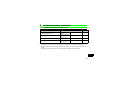
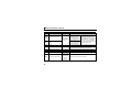
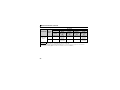
Encoder Feedback Control Parameter List
Fitting the FR-A7AL adds the following parameters for encoder control.
Refer to the Instruction Manual of the Inverter for details of parameter.
Parameter
Number
359
367
368
369
374
376
32
Name
Encoder rotation direction
Speed feedback range
Feedback gain
Number of encoder pulses
Overspeed detection level
Encoder signal loss detection
enable/disable selection
Setting Range
Increments
Initial Value
0, 1
0 to 400Hz, 9999
0 to 100
0 to 4096
0 to 400Hz
1
0.01Hz
0.1
1
0.01Hz
1
9999
1
1024
140Hz
0, 1
1
0
5
VECTOR CONTROL
When the FR-A7AL is mounted on the FR-A700 series, full-scale vector control operation can be performed
using a motor with encoder.
Speed control, torque control, position control (simple position control with the inverter and FR-A7AL, FRA7AL and positioning module of the programmable controller (MELSEC-QD75D, etc.)) by vector control
can be performed. (Refer to the Instruction Manual of the Inverter for details.)
Refer to Chapter 6 when performing position control using the positioning module of the programmable
controller.
5
33
VECTOR CONTROL
5.1
Wiring Example
(1) Standard motor with encoder, 5V differential line driver (speed control)
MCCB
Three-phase
AC power
supply
Forward rotation start
Reverse rotation start
Contact input common
Frequency command 3
2
Frequency setting
potentiometer
1/2W1kΩ 1
Torque limit
(+)
command (-)
( 10V)
34
MC
Inverter
R/L1
S/L2
T/L3
U
V
W
STF
STR
FR-A7AL
PA
SD
10
2
5
1
SF-JR motor with encoder
U
V
IM
W
E
Earth
(Ground)
*1
C
PAR
R
PB
A
PBR
N
Complementary
B
PZ
PZR
Differential
P
PG
H
SD
K
Encoder
*2
PG
SD
*6
Terminating
*4 resistor
OFF
ON
*3
(+)
*5
(-) 5VDC power supply
VECTOR CONTROL
*1
*2
*3
*4
*5
*6
The pin number differs according to the encoder used.
Speed control and torque control are properly performed even without connecting Z-phase.
The encoder should be coupled on the same axis with the motor shaft without any mechanical looseness.
Speed ratio should be 1:1.
Earth (Ground) the shielded cable of the encoder cable to the enclosure with a P clip, etc. (Refer to page 12)
For the differential line driver, set the terminating resistor selection switch to ON position. (Refer to page 10)
Note that the terminating resistor switch should be set to OFF position (initial status) when sharing the same encoder with other
unit (CNC, etc) and a terminating resistor is connected to other unit.
A separate power supply of 5V/12V/15V/24V is necessary according to the encoder power specification. When the encoder
output is the differential line driver type, only 5V can be input.
Make the voltage of the external power supply the same as the encoder output voltage, and connect the external power supply
between PG and SD.
When performing orientation control together, an encoder and power supply can be shared.
Refer to page 17 for terminal compatibility of the FR-JCBL, FR-V7CBL and FR-A7AL.
5
35
VECTOR CONTROL
(2) Vector control dedicated motor (SF-V5RU), 12V complementary (torque control)
MC
MCCB
OCR
Three-phase
AC power supply
U
V
W
Inverter
MCCB
Three-phase
AC power
supply
Forward rotation start
Reverse rotation start
Contact input common
Speed limit command
Frequency setting
potentiometer
1/2W1kΩ
Torque command (+)
( 10V) (-)
2
1
R/L1
S/L2
PC
T/L3 External
thermal CS(OH)
relay input *8 SD
STF
FR-A7AL
STR
PA
SD
10
3
2W1kΩ
G1
G2
A
PAR
B
PB
C
PBR
D
PZ
PZR
F
Complementary
G
IM
Thermal relay
protector
*1
Encoder
*2
S
Differential PG
SD
R
PG
1
SD
*6
Terminating
*4
resistor
OFF
36
FAN
U
V
W
E
Earth (Ground)
2
5
SF-V5RU
A
B
C
*7
ON
(+)
12VDC
(-) power supply *5
VECTOR CONTROL
*1
*2
*3
*4
*5
*6
*7
*8
The pin number differs according to the encoder used.
Speed control and torque control are properly performed even without connecting Z-phase.
The encoder should be coupled on the same axis with the motor shaft without any mechanical looseness.
Speed ratio should be 1:1.
Earth (Ground) the shielded cable of the encoder cable to the enclosure with a P clip, etc. (Refer to page 12)
For the complementary, set the terminating resistor selection switch to OFF position (initial status) to use. (Refer to page 10)
A separate power supply of 5V/12V/15V/24V is necessary according to the encoder power specification. When the encoder
output is the differential line driver type, only 5V can be input. Make the voltage of the external power supply the same as the
encoder output voltage, and connect the external power supply between PG and SD.
When performing orientation control together, an encoder and power supply can be shared.
Refer to page 17 for terminal compatibility of the FR-JCBL, FR-V7CBL and FR-A7AL.
For the fan of the 7.5kW or lower dedicated motor, the power supply is single phase (200V/50Hz, 200 to 230V/60Hz).
Assign OH (external thermal input) signal to the terminal CS. (Set "7" in Pr. 186.)
CS(OH)
Connect a 2W1kΩ resistor between the terminal PC and CS (CH).
Install the resistor pushing it against the bottom part of the terminal block so as to
PC
avoid a contact with other cables.
Control circuit
Refer to the Instruction Manual of the Inverter for details of Pr. 186 CS terminal function
terminal block
selection.
Resistor (2W1kΩ)
5
37
VECTOR CONTROL
5.2
Terminals
Terminal
Symbol
PA
PAR
PB
PBR
PZ
PZR
PG
SD
38
Terminal Name
Encoder A-phase signal
input
Encoder A-phase inverse
signal input
Encoder B-phase signal
input
Encoder B-phase inverse
signal input
Encoder Z-phase signal
input
Encoder Z-phase inverse
signal input
Power supply (positive
side) input
Power ground
Description
A-, B- and Z-phase signals are input from the encoder.
(For details of pulse signal, refer to page 18.)
Input power for the encoder power supply.
Connect the external power supply (5V, 12V, 15V, 24V) and the power cable
from encoder. When the encoder output is the differential line driver type,
only 5V can be input. Make sure the voltage of the external power supply is
the same as the encoder output voltage.
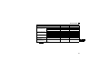
VECTOR CONTROL
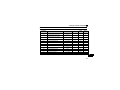
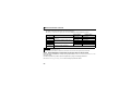
5.3
Vector Control Extended Parameter List
The following parameters for orientation control are available when used with the FR-A7AL.
Refer to the Instruction Manual of the Inverter for details of parameter.
Parameter
Number
359
369
374
376
419
420
421
Encoder rotation direction
Number of encoder pulses
Overspeed detection level
Encoder signal loss detection enable/
disable selection
Position command source selection
Command pulse scaling factor numerator
Command pulse scaling factor
denominator
0, 1
0 to 4096
0 to 400Hz
1
1
0.01Hz
1
1024
140Hz
0, 1
1
0
0, 1, 2 *1
0 to 32767 *2
1
1
0
1
0 to 32767 *2
1
1
0 to 150sec-1
0 to 100%
1sec-1
1%
25sec-1
0
0 to 50s
0.001s
0s
0 to 5s
0 to 32767 pulses *2
0.001s
1
0s
100
Position loop gain
423
Position feed forward gain
Position command acceleration/
deceleration time constant
Position feed forward command filter
In-position width
425
426
*2
Setting Range
422
424
*1
Name
Increments Initial Value
5
When the FR-A7AL is mounted, Pr. 419 = "1" (pulse position command by the FR-A7AL) can be set. When the FR-A7AL is not
mounted, E.OPT is displayed.
When the operation panel (FR-DU07) is used, the maximum setting is 9999. When a parameter unit is used, up to the
maximum value within the setting range can be set.
39
VECTOR CONTROL
Parameter
Number
427
428
429
430
432
433
464
465
466
467
468
469
470
471
472
473
474
475
476
40
Name
Setting Range
Increments Initial Value
Excessive level error
Command pulse selection
Clear signal selection
Pulse monitor selection
Pulse train torque command bias
Pulse train torque command gain
Digital position control sudden stop
deceleration time
First position feed amount lower 4 digits
First position feed amount upper 4 digits
Second position feed amount lower 4
digits
Second position feed amount upper 4
digits
Third position feed amount lower 4 digits
Third position feed amount upper 4 digits
Fourth position feed amount lower 4 digits
Fourth position feed amount upper 4
digits
Fifth position feed amount lower 4 digits
Fifth position feed amount upper 4 digits
Sixth position feed amount lower 4 digits
Sixth position feed amount upper 4 digits
0 to 400K, 9999
0 to 5
0, 1
0 to 5, 9999
0 to 400%
0 to 400%
1K
1
1
1
1%
1%
40K
0
1
9999
0
150%
0 to 360.0s
0.1s
0
0 to 9999
0 to 9999
1
1
0
0
0 to 9999
1
0
0 to 9999
1
0
0 to 9999
0 to 9999
0 to 9999
1
1
1
0
0
0
0 to 9999
1
0
0 to 9999
0 to 9999
0 to 9999
0 to 9999
1
1
1
1
0
0
0
0
VECTOR CONTROL
Parameter
Number
477
478
479
480
481
482
483
484
485
486
487
488
489
490
491
Name
Seventh position feed amount lower 4
digits
Seventh position feed amount upper 4
digits
Eighth position feed amount lower 4 digits
Eighth position feed amount upper 4 digits
Ninth position feed amount lower 4 digits
Ninth position feed amount upper 4 digits
Tenth position feed amount lower 4 digits
Tenth position feed amount upper 4 digits
Eleventh position feed amount lower 4
digits
Eleventh position feed amount upper 4
digits
Twelfth position feed amount lower 4
digits
Twelfth position feed amount upper 4
digits
Thirteenth position feed amount lower 4
digits
Thirteenth position feed amount upper 4
digits
Fourteenth position feed amount lower 4
digits
Setting Range
Increments Initial Value
0 to 9999
1
0
0 to 9999
1
0
0 to 9999
0 to 9999
0 to 9999
0 to 9999
0 to 9999
0 to 9999
1
1
1
1
1
1
0
0
0
0
0
0
0 to 9999
1
0
0 to 9999
1
0
0 to 9999
1
0
0 to 9999
1
0
0 to 9999
1
0
0 to 9999
1
0
0 to 9999
1
0
5
41
VECTOR CONTROL
Parameter
Number
492
493
494
802
823
833
840
841
842
843
844
845
846
847
848
853
873
42
Name
Fourteenth position feed amount upper 4
digits
Fifteenth position feed amount lower 4
digits
Fifteenth position feed amount upper 4
digits
Pre-excitation selection
Speed detection filter 1
Speed detection filter 2
Torque bias selection
Torque bias 1
Torque bias 2
Torque bias 3
Torque bias filter
Torque bias operation time
Torque bias balance compensation
Fall-time torque bias terminal 1 bias
Fall-time torque bias terminal 1 gain
Speed deviation time
Speed limit
Setting Range
Increments Initial Value
0 to 9999
1
0
0 to 9999
1
0
0 to 9999
1
0
0, 1
0 to 0.1s
0 to 0.1s, 9999
0 to 3, 9999
600 to 1400%, 9999
600 to 1400%, 9999
600 to 1400%, 9999
0 to 5s, 9999
0 to 5s, 9999
0 to 10V, 9999
0 to 400%, 9999
0 to 400%, 9999
0 to 100s
0 to 120Hz
1
0.001s
0.001s
1
1%
1%
1%
0.001s
0.01s
0.1V
1%
1%
0.1s
0.01Hz
0
0.001s
9999
9999
9999
9999
9999
9999
9999
9999
9999
9999
1s
20Hz
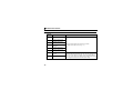
VECTOR CONTROL
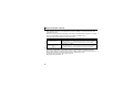
5.4
Pulse Train Torque Command
5.4.1
Parameter list
Set the following parameters to give torque command by pulse train.
Parameter
Number
432
433
800
804
5.4.2
Name
Pulse train torque command bias
Pulse train torque command gain
Control method selection
Torque command source selection
Setting Range
Initial Value
0 to 400%
0 to 400%
0 to 5, 9 to 12, 20
0 to 6
0%
150%
20
0
Pulse train torque command
(1) Pulse train torque command setting
When torque control is selected, setting "2" in Pr. 804 Torque command source selection enables torque
command by pulse train input. Set the Pr. 800 setting to "1, 2, or 5" to perform torque control. (When
setting "2 or 5", torque control need to be selected by MC terminal switchover.)
The inverter and torque command pulse train interface should be matched. (Refer to page 34 for
wiring.)
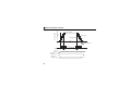
(2) Pulse train torque command
Torque command value
calibration
Pr. 433 setting
Set bias (Pr. 432) and gain (Pr. 433) to
the torque command. The relationship Pr. 433 setting
between input pulse and torque
Pulse train
400kpps input frequency
0
command value is shown on the right.
43
5
VECTOR CONTROL
(3) Pulse train input type
Use Pr. 428 Command pulse selection to select a pulse train type for commands. Refer to page 60 for the
details of Pr. 428 Command pulse selection.
5.5
Specifications
Speed control range
Speed variation ratio
Speed control
Torque control
Function
*1
*2
44
Speed response
Maximum speed
Torque control range
Absolute torque
accuracy
Repeated torque
accuracy
1 : 1500 (both driving/regeneration *1)
±0.01% (100% means 3000r/min)
300rad/s
Note that the internal response is 600rad/s (with model adaptive speed
control)
120Hz
1: 50
±10% *2
±5% *2
y Setting of speed feedback range
y Setting of feedback gain
y Setting of encoder rotation direction
Regeneration unit (option) is necessary for regeneration
With online auto tuning (adaptive magnetic flux observer), dedicated motor, rated load
6
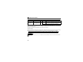
6.1
POSITION CONTROL FUNCTION
Position Control by Vector Control
Purpose
Position control by the programmable
controller positioning module
Adjust the gear ratio of motor and machine
Setting of positioning adjustment parameter
Improve position control accuracy
6.1.1
Parameter That Should Be Set
Pulse train position
command
Setting the electronic
gear
In-position width
excessive level error
Gain adjustment of
position control
Refer to
Page
Pr. 419, Pr. 428 to Pr. 430
67
Pr. 420, Pr. 421, Pr. 424
54
Pr. 426, Pr. 427
67
Pr. 422, Pr. 423, Pr. 425
68
Position control
y In the position control, the speed command given to rotate the motor is calculated to eliminate the
difference between command pulse (or parameter setting) and the number of feedback pulses from the
encoder.
y This option enables position control by the programmable controller positioning module.
6
45
POSITION CONTROL FUNCTION
Setting procedure
Perform secure wiring.
(Refer to page 48.)
Mount the FR-A7AL.
Set the motor and encoder.
(Pr. 71, Pr. 359, Pr. 369)
Set Pr. 71 Applied motor, Pr. 359 Encoder rotation direction and
Pr. 369 Number of encoder pulses according to the motor and
encoder used. (Refer to page 20)
Set the motor capacity and the number of motor poles.
(Pr. 80, Pr. 81)
(Refer to the Instruction Manual of the Inverter)
Set the motor capacity (kW) in Pr. 80 Motor capacity and set
the number of motor poles in Pr. 81 Number of motor poles.
(V/F control is performed when the setting is "9999" (initial
value).)
Select a control method. (Refer to page 64)
Make speed control valid by setting "3" (position control), "4"
(speed-position switchover) or "5" (position-torque switchover)
in Pr. 800.
46
POSITION CONTROL FUNCTION
Selection of position command source (Pr. 419.)
Set "1" in Pr.419 for position control by the
programmable controller positioning unit.
Setting of parameter for position feed (Pr. 465 to Pr. 494)
(Refer to page 39.)
Test run
As required
y Setting of the electronic gear (refer to page 54)
y Setting of positioning adjustment parameter (refer to page 67)
y Gain adjustment of position control (refer to page 68)
CAUTION
y The carrier frequencies are selectable from among 2k, 6k, 10k, 14kHz for vector control. (2k and 6kHz for the
75K* or higher)
y When performing simple position feed by contact input and position control by the inverter simple pulse train
input, refer to the Instruction Manual of the Inverter.
* 75K ⋅⋅⋅ FR-A720-75K (FR-A720-02880-NA), FR-A740-75K (FR-A740-01440-NA, FR-A740-02160-EC), FR-A760-01040-NA
47
6
POSITION CONTROL FUNCTION
6.2
Wiring Example
Connection with the MELSEC-Q series QD75D positioning module
MCCB
MC
OCR SF-V5RU, SF-THY
A
B
FAN
C
*8
Three-phase
AC power supply
MCCB
Three-phase
AC power
supply
Forward stroke end
Reverse stroke end
Pre-excitation (servo on)
Positioning module
MELSEQ-Q QD75D
Torque limit
command (+)
(±10V) (-)
R/L1
S/L2
T/L3
Inverter
STF
STR
External
thermal relay PC
input *9 CS(OH)
LX *7
SD
STOP
SD
CLEAR
CR
CLEAR COM
PGO24
PGO COM
RDY COM
COM
READY
48
Complementary
PP
PGP
PULSE R
IM
Thermal
relay
protector
FR-A7AL
DOG
*10
2W1kΩ
U
V
W
E
Earth
(Ground)
G1
G2
SD
1
5
FLS
RLS
PULSE F
U
V
W
NP OFF
A
B
PB
C
PBR
D
Terminating
resistor PZ
ON
F
Differential
*4
PA
PAR
PGN
PZR
G
SD
VDD
PG
S
SD
R
OP
PG
VDD
OPC
RDY
SD
*6
*1
Encoder
*2
*3
(+)
(-) 12VDC power
supply *5
POSITION CONTROL FUNCTION
*1
The pin number differs according to the encoder used.
Position control by pulse train input is properly performed even without connecting Z phase.
*2
The encoder should be coupled on the same axis with the motor shaft without any mechanical looseness.
Speed ratio should be 1:1.
*3
*4
Earth (Ground) the shielded cable of the encoder cable to the enclosure with a P clip, etc. (Refer to page 12)
For the complementary, set the terminating resistor selection switch to OFF position (initial status) to use. (Refer to page 10)
*5
A separate power supply of 5V/12V/15V/24V is necessary according to the encoder power specification. When the encoder output is the
differential line driver type, only 5V can be input.
Make the voltage of the external power supply the same as the encoder output voltage, and connect the external power supply between PG
and SD.
*6
*7
Refer to page 17 for terminal compatibility of the FR-JCBL, FR-V7CBL and FR-A7AP.
Assign the function using Pr. 180 to Pr. 185, Pr. 187 to Pr. 189 (input terminal function selection).
*8
*9
For the fan of the 7.5kW or lower dedicated motor, the power supply is single phase (200V/50Hz, 200 to 230V/60Hz).
Assign OH (external thermal input) signal to the terminal CS. (Pr. 186 = "7")
Connect a 2W1kΩ resistor between the terminal PC and CS (OH).
Install the resistor pushing it against the bottom part of the terminal block so as to avoid a contact
with other cables.
Refer to the Instruction Manual of the Inverter for details of Pr. 186 CS terminal function selection.
*10
Pulse signal from the positioning unit can be output by either open collector or differential line
driver. Note that connection is not the same. (The figure shows the connection in case of
differential line driver. Refer to terminal description on page 50 for connection.
CS(OH)
PC
Control circuit
terminal block
Resistor (2W1kΩ)
6
49
POSITION CONTROL FUNCTION
6.3
Terminals
Terminal
Symbol
Terminal Name
PGP
PP
Forward rotation pulse
train
PGN
NP
Reverse rotation pulse
train
CR
Clear
OPC
Open collector power input
SD
VDD
Contact input common
RDY
Preparation ready signal
OP
50
Driver power supply
Encoder Z-phase output
Specification
Description
Forward rotation pulse
train input terminal.
Input pulse train from the
Open collector pulse generating unit.
/differential line
Reverse rotation pulse
driver
train input terminal.
Input pulse train from the
pulse generating unit.
—
24VDC
—
24VDC
—
For open collector, connect
terminal VDD and OPC, then
input pulses across terminal PPSD and NP-SD. For differential
line driver, open terminal OPC,
then input pulse across terminal
PP-PGP and NP-PGN.
Shorting terminal CR-SD clears counter at the falling edge.
When inputting pulse by open collector method, connect
this terminal to terminal VDD (24V power supply).
Contact input common terminal. Do not earth (ground).
Driver power supply terminal for interface.
When servo ON and ready to drive, the signal is output.
Open collector
output
permissible
Outputs one pulse per motor revolution.
load
24VDC,
max. 50mA
POSITION CONTROL FUNCTION
6.4
Operation
The speed command given to rotate the motor is calculated to eliminate the difference between the
number of pulse train pulses and the number of pulses feed back from the motor end encoder.
1) When a pulse train (MELSEC-Q series positioning module QD75D, etc.) is input, pulses are
accumulated in the deviation counter and these droop pulses act as position control pulses to give the
speed command.
2) As soon as the motor starts running under the speed command of the inverter, the encoder generates
feed back pulses and the droop of the deviation counter is counted down. The deviation counter
maintains a given droop pulse value to keep the motor running.
3) When the command pulse input stops, the droop pulses of the deviation counter decreases, reducing
the speed. The motor stops when there are no droop pulses.
4) When the number of droop pulses has fallen below the value set in Pr. 426 In-position width, it is
regarded as completion of positioning and the in-position signal (Y36) turns on.
6
51
Command pulse frequency
[PPS]
Motor speed [r/min]
POSITION CONTROL FUNCTION
Droop pulse value
Motor speed
Pulse distribution
Acceleration
Time
Deceleration
Stop settling time
Pulse train Rough
LX signal
Servo on
STF (STR)
Forward (reverse)
Y36 signal
In-position signal
52
Fine
Rough
POSITION CONTROL FUNCTION
z The pulse train is rough during acceleration and fine at the maximum speed. During deceleration the pulse
train is rough and at last there are no pulses. The motor stops shortly after the command pulses stop. This
time lag is necessary for maintaining the stop accuracy and called stop settling time.
REMARKS
y For the servo on signal (LX), set "23" in Pr. 178 to Pr. 189 (input terminal function selection) to assign the function.
y For the in-position signal (Y36), set "36" in Pr. 190 to Pr. 196 (output terminal function selection) to assign the function.
6.4.1
Operation by position command using pulse train
Turning ON (short the terminal LX-SD) the servo on signal cancels the base circuit shut-off and operation
ready signal is output after 0.1s has passed. (Assign the servo on (LX) signal using input function selection
(Pr. 178 to Pr. 189).) When the terminal STF (forward stroke end signal) or terminal STR (reverse stroke end
signal) and terminal SD are shorted, the motor runs in accordance with the command pulse. When the
forward (reverse) stroke end signal opens, the motor does not run in that direction.
Forward rotation
Actual rotation
Reverse rotation
Base signal
Servo on (LX)
Forward stroke end (STF)
Reverse stroke end (STR)
Operation ready completion (RDY)
0.1s
Forward rotation pulse train (PGP/PP)
Reverse rotation pulse train (PGN/NP)
6
In-position (Y36)
53
POSITION CONTROL FUNCTION
6.4.2
Initial setting
(1) Shorting the terminal LX-SD (servo on) switches the servo on and cancels the base circuit shut-off,
resulting in a servo lock status.
(2) Opening terminal LX-SD shutting the base circuit.
(3) Short the terminal STF (forward rotation stroke end) or terminal STR (reverse rotation stroke end) and
the SD terminal.
(4) When command pulse is input, the motor rotates in response to the pulse command.
6.4.3
Setting the electronic gear (Pr. 420, Pr. 421, Pr. 424)
Set the ratio of the machine side gear and the motor side gear.
Parameter
Number
420
421
424
Name
Command pulse scaling
factor numerator
Command pulse scaling
factor denominator
Position command
acceleration/
deceleration time
constant
Initial
Setting
Value
Range
1
0 to 32767 *
1
0 to 32767 *
0s
0 to 50s
Description
Set the electronic gear.
Pr. 420 is a numerator and Pr. 421 is a denominator.
Use this parameter when rotation has become
unsmooth at a large electronic gear ratio (about 10
times or more) and low speed.
The above parameters can be set when the FR-A7AL (option) is mounted.
* When the operation panel (FR-DU07) is used, the maximum setting is 9999. When a parameter unit is used, up to the maximum value
within the setting range can be set.
54
POSITION CONTROL FUNCTION
(1) Calculation of the gear ratio (Pr. 420, Pr. 421)
y The position resolution (travel per pulse Δ [mm]) is determined by the travel per motor revolution
Δs [mm] and the feedback pulses Pf [pulse/rev] of the encoder, and is represented by the following
expression.
×
Δ
Δs
Pf
Δ
Δs
: travel per pulse
: travel per motor rotation
Pf
: number of feedback pulses [pulse/rev]
(number of pulses after multiplying the number of encoder pulses by four)
[mm]
[mm]
Using the parameters, the travel per command pulse can be set separately to set the travel per
command pulse without a fraction.
=
Δ
Δs
Pf
×
Pr. 420
Pr. 421
In addition, the relationship between the motor speed and internal command pulse frequency is as
follows:
fo
×
Pr. 420
Pr. 421
= Pf ×
No
60
fo: internal command pulse frequency [pps]
No: motor speed [r/min]
CAUTION
Set the electronic gear in the range of 1/50 to 20.
Note that setting a too small value will decrease the speed command and setting a too large value will increase the
speed ripples.
55
6
POSITION CONTROL FUNCTION
"Setting example 1"
Example of setting the command pulse scale factor (Pr. 420, Pr. 421) when the QD75D is used
Find the command pulse scale factor for running the motor at 1500 (r/min) at the input pulse train frequency of
100 (kpps).
y When the SF-V5RU motor is used
Number of feed back pulses is Pf = 8192 (pulse/rev)
Pr. 420
=
Pr. 421
8192
×
=
8192
×
No
60
1500
60
×
×
1
fo
1
100 ×
103
Therefore, set "2048" in Pr. 420 and "1000" in Pr. 421.
56
=
2048
1000
POSITION CONTROL FUNCTION
"Setting example 2"
Find the command pulse frequency which sets the motor speed No = 3000 (r/min).
Note that the command pulse scaling factor Pr. 420/Pr. 421 = "1".
y When the SF-V5RU motor is used
Number of feed back pulses is Pf = 8192 (pulse/rev)
fo
=
8192
×
No
60
×
=
8192
×
3000
60
×
Pr. 421
Pr. 420
1
1
=
409.6 × 10³
Therefore the command pulse is 409.6 (kpps).
CAUTION
If the pulse train input is open collector, command pulse frequency is max. 200kpps.
Therefore, the command pulse frequency should be set to 200kpps using command pulse scaling factor of Pr. 420/
Pr. 421.
6
57
POSITION CONTROL FUNCTION
(2) Relationship between position resolution Δ
and overall accuracy
Since overall accuracy (positioning accuracy of machine) is the sum of electrical error and mechanical error,
normally take measures to prevent the electrical system error from affecting the overall error. As a guideline,
refer to the following relationship.
1
1
to
) × Δε
5
10
< Stopping characteristic of motor >
< (
Δ
Δε: positioning accuracy
When parameters are used to run the motor, the internal command pulse frequency and motor speed have
the relationship as shown in the figure on page 52, and as the motor speed decreases, pulses are
accumulated in the deviation counter of the inverter. These pulses are called droop pulses (ε) and the
relationship between command frequency (fo) and position loop gain (Kp: Pr. 422) is as represented by the
following formula.
fo
204800
[pulse]
ε =
[pulse] (rated motor speed)
Kp
25
When the initial value of Kp is 25s-1, the droop pulses (ε) are 8192 pulses.
ε
=
Since the inverter has droop pulses during operation, a stop settling time (ts), which is the time between the
zero command output and the motor stop, is required. Set the operation pattern in consideration of the stop
settling time.
1
[s]
Kp
When the initial value of Kp is 25s-1, the stop settling time (ts) is 0.12s.
The positioning accuracy Δ ε is (5 to 10) × Δ = Δ ε [mm]
ts = 3 ×
58
POSITION CONTROL FUNCTION
CAUTION
The stop settling time (ts) indicates the time for the motor to enter within the positioning accuracy range. It does
not indicate the time required for the motor to stop completely. When high positioning accuracy is required for the
travel per pulse (Δ ) in high duty applications, for example, a longer setting time than the value derived from the
above formula must be considered. Note that ts also differs with the conditions of the moving sections.
Particularly at a large load friction torque, the motor may run unstably when it is coming to a stop.
(3) Position command acceleration/deceleration time constant (Pr. 424)
y When the electronic gear ratio is large (about 10 or more times) and the speed is low, rotation will not
be smooth, resulting in pulse-wise rotation. At such a time, set this parameter to smooth the rotation.
y When acceleration/deceleration time cannot be provided for the command pulses, a sudden change in
command pulse frequency may cause an overshoot or error excess alarm. At such a time, set this
parameter to provide acceleration/deceleration time.
Normally it is set to 0.
6
59
POSITION CONTROL FUNCTION
6.5
Pulse Input Type
Command pulse can be changed according to the positioning module as in the table below.
(1) Pulse train form (Pr. 428)
Negative logic
Command Pulse
At Forward
Train Form
Rotation
Forward
rotation pulse
train
PP
Reverse
NP
rotation pulse
train
60
Pulse train + PP
sign
NP
A phase pulse
train
PP
B phase pulse NP
train
L
At Reverse
Rotation
Setting
Pr. 428
Remarks
QD75D(CW/CWW mode)
0
(Note) If (CW/CWW mode) and (PLS/
(initial setting) SIGN mode) are misselected, the motor
runs only in one direction.
1
QD75D (PLS/SIGN mode)
2
Counted after multiplying by four.
Set the pulse train frequency multiplied
by four to 500kpps or less with the
differential driver type and to 200kpps or
less with the open collector type.
H
POSITION CONTROL FUNCTION
Positive logic
Command Pulse
At Forward
Train Form
Rotation
Forward
rotation pulse
train
PP
Reverse
NP
rotation pulse
train
Pulse train +
sign
At Reverse
Rotation
PP
NP
A phase pulse
train
PP
B phase pulse NP
train
H
L
Setting
Pr. 428
Remarks
3
—
4
—
5
Counted after being multiplied by four.
Set the pulse train frequency multiplied
by four to 500kpps or less with the
differential driver type and to 200kpps or
less with the open collector type.
6
61
POSITION CONTROL FUNCTION
6.6
Interface of the Positioning Module and Inverter
When running the inverter by each positioning module, interface of the positioning command pulse train
need to be matched.
Output Type
Hardware Configuration
Command unit
Input Pulse Frequency
Inverter (FR-A7AL)
Connect
externally
+24
VDD
OPC
Open collector
Max. 200kpps
PP(NP)
SD
*: Wiring length : max. 2m
Command unit
Differential line
driver
Do not
connect
Inverter (FR-A7AL)
VDD
OPC
PP(NP)
PGP(PGN)
*: Wiring length : max. 10m
62
+24
Max. 500kpps
POSITION CONTROL FUNCTION
6.7
Extended Function Parameter List
The following parameters for position control are available when used with the FR-A7AL. (except for Pr. 800)
Parameter
Number
419
420
421
Name
Position command source selection
Command pulse scaling factor
numerator
Command pulse scaling factor
denominator
422
Position loop gain
423
425
426
Position feed forward gain
Position command acceleration/
deceleration time constant
Position feed forward command filter
In-position width
427
Excessive level error
428
429
430
800
Command pulse selection
Clear signal selection
Pulse monitor selection
Control method selection
424
Setting Range
Increments
Initial
Value
Refer to
Page
0, 1, 2 *
1
0
67
0 to 32767
1
1
54
0 to 32767
1
1
54
0 to 150s-1
0 to 100%
1s-1
1%
25s-1
0%
68
0 to 50s
0.001s
0s
54
0 to 5s
0 to 32767 pulses
0 to 400K pulse,
9999
0 to 5
0, 1
0 to 5, 9999
0 to 5, 9 to 12, 20
0.001s
1 pulses
0s
100 pulses
68
67
1K pulses
40K pulses
67
1
1
1
1
0
1
9999
20
60
71
68
64
68
* When the FR-A7AL is fitted, Pr. 419 = "1" (pulse position command by the FR-A7AL) is valid. When the FR-A7AL is not
fitted, E.OPT is displayed.
6
63
POSITION CONTROL FUNCTION
6.8
Parameter Setting and Details
When performing position control with the FR-A7AL, set the following parameters.
6.8.1
Block diagram
Inverter
Position feed
forward
command filter Position feed
forward gain
Pr. 425
Pr. 423
Position command
Position command source selection
Pr. 419
Parameter
FR-A7AL pulse
train input
Inverter pulse
train input
6.8.2
0
1
Command
pulse
selection
Pr. 428
Position command
acceleration/deceleration
time constant
Electronic Pr. 424
gear
Pr.420
+
Pr.421
-
2
Position
loop gain
Pr. 422 + Speed control
+
Deviation
IM
counter
Pr. 429
Clear signal
selection
S
Encoder
Position feedback
Selection of control method (Pr. 800)
Set the Pr. 800 setting to "3, 4, 5" to perform position control. Control circuit terminal function changes
depending on parameter setting.
(When the setting is "4 or 5", select position control by switching MC signal.)
64
POSITION CONTROL FUNCTION
Refer to the Instruction Manual of the Inverter for details.
Pr. 800
Setting
Control Method
Control Mode
0
Speed control
1
Torque control
2
Speed control-torque control
switchover
3
Vector control
Remarks
—
—
MC signal: ON Torque control
MC signal: OFF Speed control
Position control
—
4
Speed control-position control
switchover
MC signal: ON Position control
MC signal: OFF Speed control
5
Position control-torque control
switchover
MC signal: ON Torque control
MC signal: OFF Position control
9
Vector control test operation
10
Speed control
—
11
Torque control
—
12
20
(initial
value)
Real sensorless vector control
Speed control-torque control
switchover
MC signal: ON Torque control
MC signal: OFF Speed control
V/F control or Advanced magnetic flux vector control
6
65
POSITION CONTROL FUNCTION
Terminal function changes by control mode switchover as below.
Description
Classification
Terminal
Name
Pr. 800 = "3"
Position
control
STF
Forward stroke
end
STR
Reverse stroke
end
Contact input
signal
Pr. 800 = "4"
Speed
control
MC signal:
OFF
Forward
rotation
command
Reverse
rotation
command
Pr. 800 = "5"
Position
control
MC signal:
ON
Position
control
MC signal:
OFF
Forward stroke
end
Forward stroke
end
Reverse stroke
end
Reverse stroke
end
Torque
control
MC signal:
ON
Forward
rotation
command
Reverse
rotation
command
REMARKS
Assign MC signal to Pr. 180 to Pr. 188. Set any of Pr. 180 to Pr. 188 to "26".
For analog input terminal, function changes according to Pr. 858 Terminal 4 function assignment, Pr. 868 Terminal 1
function assignment setting. (Refer to the Instruction Manual of the Inverter for details.)
66
POSITION CONTROL FUNCTION
6.8.3
Position control
(1) Position command source selection (Pr. 419)
When using the FR-A7AL, set "1" in Pr. 419.
Pr. 419 Setting
0 (initial value)
1
2
Description
Conditional position feed function by contact input (by parameter).
Position command by pulse train input (when the FR-A7AL is mounted).
Conditional pulse train position command by inverter pulse train input.
(2) In-position width (Pr. 426)
The Y36 terminal signal acts as an in-position signal.
The in-position signal turns on when the number of droop pulses becomes less than the setting.
(3) Excessive level error (Pr. 427)
An error becomes excessive when the droop pulses exceed the setting.
When you decreased the position loop gain (Pr. 422) setting, increase the error excessive level setting.
Also decrease the setting when you want to detect an error slightly earlier under a large load.
When "9999" is set in Pr. 427, position error large (E.OD) does not occur regardless of droop pulses.
6
67
POSITION CONTROL FUNCTION
(4) Pulse monitor selection (Pr. 430)
The status of various pulses during running are displayed.
Set "6" in Pr. 52 DU/PU main display data selection to display the output frequency monitor.
Display Range
(FR-DU07)
Display Range
(FR-PU04, FR-PU07)
Pr. 430 Setting
Description
0
The cumulative command pulse value is
displayed.
Lower 4 digits
Upper 4 digits
Lower 5 digits
Upper 5 digits
The cumulative feedback pulse value is
displayed.
Lower 4 digits
Upper 4 digits
Lower 4 digits
Upper 4 digits
Lower 5 digits
Upper 5 digits
Lower 5 digits
Upper 5 digits
1
2
3
4
5
9999
(initial value)
The droop pulses are displayed.
Frequency monitor is displayed.
REMARKS
y The pulse count starts at servo on.
y The cumulative pulse value is cleared when the base is shut off or the clear signal (CLR) is turned ON.
6.8.4
Gain adjustment of position control (Pr. 422, Pr. 423, Pr. 425)
Easy gain tuning is available as an easy tuning method. Refer to the Instruction Manual of the Inverter for
easy gain tuning.
If it does not produce any effect, make fine adjustment by using the following parameters.
Set "0" in Pr. 819 Easy gain tuning selection before setting the parameters below.
68
POSITION CONTROL FUNCTION
Parameter
Number
Name
422
Position loop gain
423
Position feed forward gain
425
Position feed forward command
filter
Initial
Setting
Value
Range
25s-1
0 to 150s-1
0%
0 to 100%
0s
0 to 5s
Description
Set the gain of the position loop.
Function to cancel a delay caused by the
droop pulses of the deviation counter.
Enters the primary delay filter in
response to the feed forward command.
6
69
POSITION CONTROL FUNCTION
(1) Position loop gain(Pr. 422)
Make adjustment when any of such phenomena as unusual vibration, noise and overcurrent of the
motor/machine occurs.
Increasing the setting improves trackability for the position command and also improves servo rigidity
at a stop, but oppositely makes an overshoot and vibration more liable to occur.
Normally set this parameter within the range about 5 to 50.
Phenomenon/Condition
Pr. 422 Adjustment
Increase the Pr. 422 value.
Increase the value by 3s-1 until just before an overshoot, stop-time vibration or
other instable phenomenon occurs, and set about 0.8 to 0.9 of that value.
Overshoot, stop-time vibration or Decrease the Pr. 422 value.
other instable phenomenon
Decrease the value by 3s-1 until just before an overshoot, stop-time vibration or
occurs.
other instable phenomenon occurs, and set about 0.8 to 0.9 of that value.
Slow response
(2) Position feed forward gain (Pr. 423)
This function is designed to cancel a delay caused by the droop pulses of the deviation counter.
When a tracking delay for command pulses poses a problem, increase the setting gradually and use
this parameter within the range where an overshoot or vibration will not occur.
This function has no effects on servo rigidity at a stop.
Normally set this parameter to "0".
70
POSITION CONTROL FUNCTION
6.8.5
Selection of clear signal (Pr. 429, CR signal)
yUse this function to make a drooping pulse 0 for home position operation, etc.
yWhen "0" is set in Pr. 429 , the deviation counter is cleared at the edge of turning on of the clear signal (CR). The
CR signal turns on in synchronization with the zero pulse signal of encoder for home position operation, etc. and
clears the deviation counter.
When Pr. 429 = "1 (initial value)"
When Pr. 429 = "0"
Deviation counter
image
CR
Deviation counter
image
ON
Counter clear at the edge of
turning on of the signal
CR
ON
Counter clear while ON
6
71
POSITION CONTROL FUNCTION
6.8.6
Troubleshooting
Cause
Phenomenon
(1) The phase sequence of the
Countermeasures
(1) Check the wiring (Refer to page 48)
motor or encoder wiring is
wrong.
(2) The control mode selection, Pr.
(2) Check the Pr. 800 setting. (Refer to page 64)
800, setting is improper.
(3) The servo on signal or stroke
(3) Check that the signals are input normally.
end signal (STF, STR) is not
input.
(4) Command pulse, position pulse
(4)-1
sign (NP) are not correctly input.
Check that the command pulses are input
normally. (Check the cumulative command
1 Motor does not rotate
pulse value in Pr. 430)
(4)-2
Check the command pulse form and
command pulse selection, Pr. 428, setting.
(5) The Pr. 419 Position command
source selection , setting is not
(5) Check the position command source
selection in Pr. 419 .
correct.
(6) When the Pr. 419 Position
command source selection setting
is 0, the position feed amount, Pr.
465 to Pr. 494 , settings are not
correct.
72
(6) Check the position feed amount in Pr. 465 to
Pr. 494 .
POSITION CONTROL FUNCTION
Phenomenon
Cause
(1) The command pulses are not
Countermeasures
(1)-1
input correctly.
Check the command pulse form and
command pulse selection, Pr. 428, setting.
(1)-2
Check that the command pulses are input
normally. (Check the cumulative command
2 Position shift occurs.
pulse value in Pr. 430 )
(2) The command is affected by
noise. Or the encoder feedback
(2)-1
(2)-2
signal is compounded with noise.
Decrease Pr. 72 PWM frequency selection.
Change the earthing (grounding) point of
shielded wire. Or leave the cable
suspended.
3 Motor or machine hunts.
4 Machine operation is unstable
(1) The position loop gain is high.
(1)
Decrease the Pr. 422 value.
(2) The speed loop gain is high.
(2)-1
Perform easy gain tuning.
(2)-2
Decrease Pr. 820 and increase Pr. 821.
(1) The acceleration/deceleration
(1) Decrease Pr. 7 and Pr. 8.
time setting has adverse effect.
6
73
POSITION CONTROL FUNCTION
6.9
Specifications
Repeated positioning
accuracy
Holding force after
positioning
Power supply
Maximum input pulse
frequency
Positioning return
pulse
Electronic gear setting
In-position width
setting
Error excess
74
±1.5° (motor shaft end)
(changes according to load torque, moment of inertia J or backlash condition of the load)
With servo lock
24V power supply output for interface driver is provided
Differential line receiver: 500kpps, open collector: 200kpps
Number of encoder pulses per motor rotation × 4 times
1/50 to 20
0 to 32767 pulses
0 to 400K pulses
7
ENCODER PULSE DIVIDING OUTPUT
Pulse input of encoder connected to the inverter is divided and output from the FR-A7AL terminal.
7.1
Wiring Example
Motor end
encoder
A, B, Z phases
Inverter
FR-A7AL
A phase
B phase
Division ratio
1
Pr. 413 setting
Z phase *
A phase
B phase Division ratio
1
Pr. 413 setting
Z phase *
FPA2 (A phase)
FPA2 (B phase) Encoder pulse output
(open collector)
FPA2 (Z phase)
FPA (A phase)
FPAR
FPB (B phase)
FPBR
FPZ (Z phase)
FPZR
Encoder pulse output
(differential line driver)
* Z phase can not be divided.
75
7
ENCODER PULSE DIVIDING OUTPUT
CAUTION
For open collector output, the signal may become unstable if the input resistance of the connected device is
large and the device may detect the signal incorrectly. In this case, adding a pull-up resistance as shown
below will improve the phenomenon.
Select a pull-up resistance in consideration of the input current of the connected device so that the open
collector output current will not exceed the output permissible load current.
Power supply
+
Pull-up resistance
Inverter
FR-A7AL
FPA2/FPB2/FPZ2
SD
76
Connected device
ENCODER PULSE DIVIDING OUTPUT
7.2
Terminals
Open collector
Terminal
Symbol
Terminal Name
FPA2
A-phase output
FPB2
B-phase output
FPZ2
Z-phase output
Specification
Description
Open collector
Output permissible
load
24VDC, max. 50mA
A-, B- and Z-phase (origin and mark pulse) signals are
output from the encoder. A-phase and B-phase signal
is divided and can be output as division ratio (1/n)
n = 1 to 32767 (integer number).
Set the division using Pr.413 Encoder pulse division ratio.
Common terminal is terminal SD.
Specification
Description
Differential line driver
Terminal
Terminal Name
Symbol
FPA
Differential A-phase output
FPAR
FPB
FPBR
FPZ
FPZR
*1
Differential A-phase
inversion signal output
Differential B-phase output
Differential B-phase
inversion signal output
Differential Z-phase output
Differential line
driver output
Permissible load
0.1A
A-, B- and Z-phase (origin and mark pulse) signals are
output from the encoder. A-phase and B-phase signal
is divided and can be output as division ratio (1/n)
n = 1 to 32767 (integer number).
Set frequency dividing using Pr.413 Encoder pulse division
ratio.
Differential Z-phase
inversion signal output
The division ratio setting is same for open collector output and differential line driver output.
77
7
ENCODER PULSE DIVIDING OUTPUT
7.3
Encoder
Parameter
Number
Name
413
Encoder pulse division
ratio
Initial
Value
1
Setting
Range
Description
1 to 32767
The encoder pulse signal at the motor end can
be divided in division ratio set in Pr. 413 and
output. Use this parameter to make the response
of the machine to be input slower, etc.
y Division waveform by division ratio
Both ON-OFF width is division times. (50% duty)
Pulse waveform example at 1000 pulse input when Pr. 413 = "2"
Division ratio A phase
1/1
B phase
(1000 pulses)
2 divisions
Division ratio A phase
1/2
B phase
(500 pulses)
REMARKS
Control of forward rotation/reverse rotation by phase difference between A phase and B phase.
y When A phase is 90° advanced as compared to B phase: forward rotation
y When A phase is 90° behind as compared to B phase: reverse rotation
78
MEMO
79
REVISIONS
*The manual number is given on the bottom left of the back cover.
Print Date
*Manual Number
Revision
Oct. 2007
IB(NA)-0600310ENG-A First edition
Aug. 2012
IB(NA)-0600310ENG-B y Pr. 829 Number of machine end encoder pulses
y Note on the differential line driver type encoder
Addition
80
IB(NA)-0600310ENG-B
INVERTER
INVERTER
INVERTER
Plug-in option
FR-A7AL
INSTRUCTION MANUAL
ORIENTATION CONTROL
FR-A7AL
IB(NA)-0600310ENG-B(1208) MEE
Printed in Japan
Specifications subject to change without notice.
INSTRUCTION MANUAL
HEAD OFFICE: TOKYO BUILDING 2-7-3, MARUNOUCHI, CHIYODA-KU, TOKYO 100-8310, JAPAN
B
ENCODER FEEDBACK CONTROL
VECTOR CONTROL
POSITION CONTROL
ENCODER PULSE DIVIDING OUTPUT
PRE-OPERATION INSTRUCTIONS
1
INSTALLATION
2
ORIENTATION CONTROL
3
ENCODER FEEDBACK CONTROL
4
VECTOR CONTROL
5
POSITION CONTROL FUNCTION
6
ENCODER PULSE DIVIDING OUTPUT
7