1
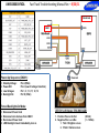
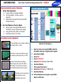
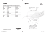
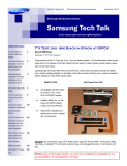
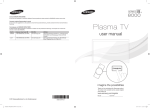
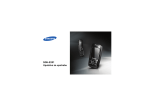
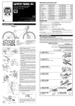
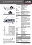
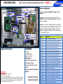
UN65D8000XFXZA Fast Track Troubleshooting Manual Rev – 8/30/11 Service Bulletins Main PCB History of Pairing with QWERTY Remote and 3D Glasses SMPS LVDS Cable Symptom: Customers are asking for replacement QWERTY remote or Bluetooth 3D glasses, even if they don’t have defects Solution: To prevent, call agent can check the history that customer already paired QWERTY remote and 3D glasses. Go to menu, support and select ''''Contact Samsung'''‘ (flagged for history). Even customers reset TV, history still remains T-CON Board Wi-Fi Module Support Information FIRMWARE HOT TIPS 6/3/2011 T-GAP8AKUC Version: 1013.2 Description: Support 3D explore and Compassion Apps. Decrease flickering on 3D mode Be sure to check for latest SW updates. Power On Problems: (see page 2) Video Problems: (see page 3) Other: If the set loses internet connectivity, the remote control no longer operates, and the 3D glasses will not link to the set, verify power supply voltages. If they are normal, replace the main board as that is the only commonality between all of the failures. Be sure to check for latest parts updates. Part No. Description BN94-04971A ASSY PCB MAIN;UN65D8000XFXZA BN95-00502A PRODUCT LCD;LD650DLB-V1,D8K 65" AUO_PANE BN96-10276B ASSY HOLDER P-RING;09 LEDTV ALL MODEL,AB BN96-10810A ASSY HOLDER P;09 LEDTV MODEL,NYRON BN96-12845D ASSY POWER CORD;125/7A, UL/CSA,LP-11WL,V BN96-12942F ASSY SPEAKER P;8OHM,4PIN,15W,UD8000 65"_ BN96-12965F ASSY SPEAKER P;4OHM,4PIN,25W,UD8000 65"_ BN96-13489C ASSY BLU P;UC65C8000XFXZA,L8065,WHITE,BL BN96-15474M ASSY BOARD P-TOUCH FUNCTION&POWER IR;UN6 BN96-15587J ASSY COVER P-FRONT;UD8000 65,W/W,MABS+PM BN96-15588M ASSY COVER P-REAR;UD8000 65,UO,PCM,T0.45 BN96-16787A ASSY STAND P-BASE;PD8000 59 BN96-17107A ASSY BOARD P-RF MODULE;BLUETOOTH MODULE, BN96-17116Q ASSY CABLE P-FFC;UN65D8000XF***,FFC,691M BN96-18927A ASSY ACCESSORY 3D GLASSES;SSG-3300GR,2EA BN96-19795A ASSY T CON P-T-CON;LD650DLB-V1 BN94-04971A ASSY PCB MAIN;UN65D8000XFXZA UN65D8000XFXZA Fast Track Troubleshooting Manual Rev – 8/30/11 CNL802 A,B CN201 Power-Up Sequence (CN201): 1. 2. 3. 4. Standby Voltage: Power-ON: Low Voltages: Backlight On: Pin 4 (5Vdc) Pin 2 (Low-Hi voltage transition) Pin 1, 3, 7, 9, 11, 12, 13 Pin 10 (5Vdc) Forced Backlight-On Mode: 1. 2. 3. 4. Disconnect Power Cord Disconnect wire harness from CN201 Re-Connect Power Cord LED Backlight should immediately turn on LED Drive Voltages (CNL802 A&B): 1. Positive Pins Lx+ & Rx+: 2. Negative Pins Lx- & Rx-: 1. 1Vdc = Brighter screen 2. 10Vdc = Darker screen (38Vdc) (1 ~ 10Vdc) UN65D8000XFXZA Fast Track Troubleshooting Manual Rev – 8/30/11 TROUBLESHOOTING VIDEO PROBLEMS 1. Verify Video Operation a) b) c) Customer Picture Test (models available) “On Screen Display” (If OSD ok, source is suspected) Substitute with known good Source (external DVD or Signal Generator) 2. Use Test Patterns in Service Mode a) b) c) Select an active source signal (HDMI preferred). Test Pattern may rely on signal source to appear. Using customer remote: Mute+1+8+2+Power Using factory remote: Info+ Factory ON SCREEN FAILURE EXAMPLES: 2011 LED TV Test Patterns If Picture & Display errors, its likely a defective Main Board, LVDS, or T-CON 1. Green lines or a green screen likely caused by a defective main board, LVDS, or T-CON Vertical or Horizontal Lines are likely a defective panel, but also T-CON, LVDS, or Main Board. Use Test Patterns in Factory Service Mode to determine error location Pixelization can be caused by the main board, but is more commonly a source error Select an active source signal (HDMI preferred). Test Pattern may rely on signal source to appear. 2. Access Service Mode 3. Access SVC 4. Access Test Patterns 5. Access Genoa-P (located on Main PCB) 6. Check Test Patterns 7. If OK, suspect input Source 8. Access Napoli (located on T-CON Board) 9. Check Test Patterns 10. If OK and Genoa-P was not good, suspect Main Board or LVDS Cable 3 UN65D8000XFXZA Fast Track Troubleshooting Manual Rev – 8/30/11 ALIGNMENTS: 1. 2. 3. 4. Check/Set Option Bytes Check/Perform Firmware upgrade for all repairs Perform reset in Service Mode and Plug & Play if Main is replaced Inform customer all settings will reset if Main PCB is replaced To enter Factory Mode: Software Upgrade: Software Upgrade can be performed by network connection or downloading the latest firmware from “www.samsung.com” to a USB memory device. -By USB Insert a USB drive containing the firmware upgrade file. DO NOT disconnect the power or remove the USB drive until upgrades are complete. The TV will be turned off and on automatically after completing the firmware upgrade. When software is upgraded, video and audio settings you have made will return to their default settings. NOTE: The displayed menu may differ depending on the model. - By Online Upgrades the software using the Internet. First, configure your network. If The internet connection doesn’t operate properly, connection can be broken, please retry downloading. If the problem still happens, download by USB and upgrade. - Standby mode upgrade(Off/On) A manual upgrade will be automatically performed at selected time. Since the power of the unit is turned on internally, the screen may be turned on slightly for the LED product. This phenomenon may continue for more than 1 hour until the software upgrade is complete. Testing Bluetooth Operation (3D glasses and QWERTY remote): Bluetooth communication will automatically activate when the TV is turned on. To test, use a cell phone with Bluetooth capabilities, and “SCAN for devices”. If Bluetooth communication is working properly, “DTVBluetooth” will appear on the phone. If not, suspect Main PCB, or Bluetooth module is defective. Message on Cell Phone Option Bytes 4