1
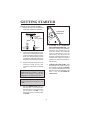
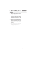
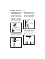
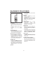
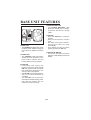
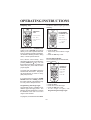
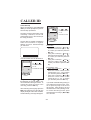
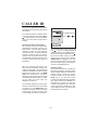
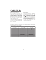
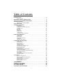
Table of Contents
INTRODUCTION . . . . . . . . . . . . . . . . . . . . . . . . . . . . . . . . . . . . . . . . . . . . . . . . 2
Parts Check List: . . . . . . . . . . . . . . . . . . . . . . . . . . . . . . . . . . . . . . . . . . . . . . . . . 3
IMPORTANT SAFETY INSTRUCTIONS . . . . . . . . . . . . . . . . . . . . . . . . . . . . . 4
REPLACING THE HANDSET BATTERIES. . . . . . . . . . . . . . . . . . . . . . . . . . . 6
GETTING STARTED . . . . . . . . . . . . . . . . . . . . . . . . . . . . . . . . . . . . . . . . . . . . 8
Setting Up Your VTech 912 ADLc . . . . . . . . . . . . . . . . . . . . . . . . . . . . . . . . . . . . 8
WALL MOUNTING . . . . . . . . . . . . . . . . . . . . . . . . . . . . . . . . . . . . . . . . . . . . . . 10
HANDSET FEATURES . . . . . . . . . . . . . . . . . . . . . . . . . . . . . . . . . . . . . . . . . . . 12
IN USE LED . . . . . . . . . . . . . . . . . . . . . . . . . . . . . . . . . . . . . . . . . . . . . . . . . . . .
LOW BATTERY LED . . . . . . . . . . . . . . . . . . . . . . . . . . . . . . . . . . . . . . . . . . . . .
PHONE KEY / FLASH FUNCTION . . . . . . . . . . . . . . . . . . . . . . . . . . . . . . . . . .
CHANNEL KEY . . . . . . . . . . . . . . . . . . . . . . . . . . . . . . . . . . . . . . . . . . . . . . . . .
OFF KEY . . . . . . . . . . . . . . . . . . . . . . . . . . . . . . . . . . . . . . . . . . . . . . . . . . . . . .
MEM KEY . . . . . . . . . . . . . . . . . . . . . . . . . . . . . . . . . . . . . . . . . . . . . . . . . . . . . .
PROG KEY . . . . . . . . . . . . . . . . . . . . . . . . . . . . . . . . . . . . . . . . . . . . . . . . . . . . .
REDIAL KEY . . . . . . . . . . . . . . . . . . . . . . . . . . . . . . . . . . . . . . . . . . . . . . . . . . .
TONE / KEY . . . . . . . . . . . . . . . . . . . . . . . . . . . . . . . . . . . . . . . . . . . . . . . . . .
VOLUME CONTROL SWITCH . . . . . . . . . . . . . . . . . . . . . . . . . . . . . . . . . . . . .
12
12
12
12
12
12
12
12
12
12
BASE UNIT FEATURES . . . . . . . . . . . . . . . . . . . . . . . . . . . . . . . . . . . . . . . . . . 13
POWER LED . . . . . . . . . . . . . . . . . . . . . . . . . . . . . . . . . . . . . . . . . . . . . . . . . . .
CHARGE LED . . . . . . . . . . . . . . . . . . . . . . . . . . . . . . . . . . . . . . . . . . . . . . . . . .
IN USE LED . . . . . . . . . . . . . . . . . . . . . . . . . . . . . . . . . . . . . . . . . . . . . . . . . . . .
SPARE BATTERY LED . . . . . . . . . . . . . . . . . . . . . . . . . . . . . . . . . . . . . . . . . . .
PAGE KEY . . . . . . . . . . . . . . . . . . . . . . . . . . . . . . . . . . . . . . . . . . . . . . . . . . . . .
TONE/PULSE SWITCH . . . . . . . . . . . . . . . . . . . . . . . . . . . . . . . . . . . . . . . . . . .
13
13
13
13
13
13
OPERATING INSTRUCTIONS . . . . . . . . . . . . . . . . . . . . . . . . . . . . . . . . . . . . . 14
Making Calls . . . . . . . . . . . . . . . . . . . . . . . . . . . . . . . . . . . . . . . . . . . . . . . . . . . .
Answering Calls . . . . . . . . . . . . . . . . . . . . . . . . . . . . . . . . . . . . . . . . . . . . . . . . .
Disconnecting . . . . . . . . . . . . . . . . . . . . . . . . . . . . . . . . . . . . . . . . . . . . . . . . . . .
Changing Channels . . . . . . . . . . . . . . . . . . . . . . . . . . . . . . . . . . . . . . . . . . . . . .
Temporary Tone . . . . . . . . . . . . . . . . . . . . . . . . . . . . . . . . . . . . . . . . . . . . . . . . .
Programming The Ringer Type . . . . . . . . . . . . . . . . . . . . . . . . . . . . . . . . . . . . .
Turning Off The Ringer . . . . . . . . . . . . . . . . . . . . . . . . . . . . . . . . . . . . . . . . . . . .
Checking The Ringer . . . . . . . . . . . . . . . . . . . . . . . . . . . . . . . . . . . . . . . . . . . . .
Memory Dialing . . . . . . . . . . . . . . . . . . . . . . . . . . . . . . . . . . . . . . . . . . . . . . . . .
Programming Speed Dial Numbers . . . . . . . . . . . . . . . . . . . . . . . . . . . . . . . . . .
Speed Number Dialing . . . . . . . . . . . . . . . . . . . . . . . . . . . . . . . . . . . . . . . . . . . .
To Change or Replace a Speed Dial Number . . . . . . . . . . . . . . . . . . . . . . . . . .
Storing Special Codes . . . . . . . . . . . . . . . . . . . . . . . . . . . . . . . . . . . . . . . . . . . .
Using Redial . . . . . . . . . . . . . . . . . . . . . . . . . . . . . . . . . . . . . . . . . . . . . . . . . . . .
Storing a Redial Number into Speed Dial . . . . . . . . . . . . . . . . . . . . . . . . . . . . . .
The Page Feature . . . . . . . . . . . . . . . . . . . . . . . . . . . . . . . . . . . . . . . . . . . . . . .
14
14
14
14
15
15
15
16
16
16
16
16
17
17
17
18
CALLER ID . . . . . . . . . . . . . . . . . . . . . . . . . . . . . . . . . . . . . . . . . . . . . . . . . . . . 19
Caller ID LCD and Icons . . . . . . . . . . . . . . . . . . . . . . . . . . . . . . . . . . . . . . . . . . .
Caller ID Operating Key Descriptions. . . . . . . . . . . . . . . . . . . . . . . . . . . . . . . . .
Caller ID Setup . . . . . . . . . . . . . . . . . . . . . . . . . . . . . . . . . . . . . . . . . . . . . . . . . .
Reviewing Caller ID Information . . . . . . . . . . . . . . . . . . . . . . . . . . . . . . . . . . . . .
Repeat Counter . . . . . . . . . . . . . . . . . . . . . . . . . . . . . . . . . . . . . . . . . . . . . . . . .
Deleting Caller ID Memory . . . . . . . . . . . . . . . . . . . . . . . . . . . . . . . . . . . . . . . . .
Manual Reset . . . . . . . . . . . . . . . . . . . . . . . . . . . . . . . . . . . . . . . . . . . . .
19
21
21
23
23
24
24
MAINTENANCE . . . . . . . . . . . . . . . . . . . . . . . . . . . . . . . . . . . . . . . . . . . . . . . .
IN CASE OF DIFFICULTY . . . . . . . . . . . . . . . . . . . . . . . . . . . . . . . . . . . . . . . .
WARRANTY STATEMENT . . . . . . . . . . . . . . . . . . . . . . . . . . . . . . . . . . . . . . . .
FCC REGULATIONS . . . . . . . . . . . . . . . . . . . . . . . . . . . . . . . . . . . . . . . . . . . .
TECHNICAL SPECIFICATIONS . . . . . . . . . . . . . . . . . . . . . . . . . . . . . . . . . . .
25
26
28
29
31
1
INTRODUCTION
Congratulations! You have purchased
one of the best performing cordless
telephones on the market! The VTech
912 ADLc is a single line 900 MHz
cordless phone with Alpha Numeric
Caller ID module in Base Unit.
The VTech 912 ADLc has automatic
security code reset. This means that
one of more than 65 thousand possible
digital security codes is randomly
selected every time the handset is
placed in the base unit. The handset
and base unit will recognize each other
based on this security code which
minimizes the chances of another
cordless phone using your telephone
line. The base unit stores the current
security code and channel in memory
even if the unit is unplugged.
Caller ID features:
• Displays Name, Number, Time &
Date of call simultaneously
• Call memory can at least keep the
latest 75 calls up to a maximum of
99 Calls
• Ability of setting current date and
time
• Forward / Backward Reviewing
capability
• Delete single/all message(s)
• "Message wait" icon indicator
• Display Time / Date & total calls in
clock mode (Standby mode)
• "REPEAT#" icon & "NEW CALL" icon
• Compatible with Single / Multiple
Message format
• 3 keys simple operation
• "New call" LED indicator
• Manual reset available
• Support 3 major languages: English,
Spanish & French
Other special features are:
• 10 Number Speed Dial Memory
• 10 Channels of operation
• Automatic Search for Available
Channel
• Manual Channel Change on Handset
• PAGE from Base to Handset
• REDIAL feature
• Programmable Ringer Types
• Low Battery Detect and Warning
indicator
• Hearing-Aid Compatible Receiver
• Easy answer - when the phone rings
simply press any key on the handset
to answer (EXCEPT OFF).
• Removable battery pack
• Extra Battery Charger in the base unit
• Touch Tone and Pulse Dialing
• Temporary Tone Mode
This manual is designed to familiarize
you with the VTech 912 ADLc. To get
the most use out of your VTech 912
ADLc, we strongly recommend you
read the manual before using your
phone.
2
INTRODUCTION
Parts Check List:
1. Handset
2. Base unit
3. AC adapter
4. Telephone line cord
5. Battery pack
6. Wall mounting bracket
900 MHz
900MHz
CORDLESS
LOW
BATT
IN USE
PHONE
CALLER ID
912ADLc
CHAN
OFF
1
2 ABC
3 DEF
4 GHI
5 JKL
6 MNO
7 PRS
8 TUV
9 WXY
0OPER
#
POWER
IN USE
*
TONE
PROG
CHARGING
NEW
CALL
SPARE
BATT
DEL
MEM
REDIAL
PAGE
BASE UNIT
HANDSET
BatteryPack
80-4032-00-00
3.6v600mAhNi-Cd
WARNING:DONOTBURN
ORPUNCTUREBATTERIES
Ni-Cd
AC ADAPTER
BATTERY PACK
WALL MOUNTING
BRACKET
TELEPHONE LINE CORD
3
IMPORTANT SAFETY INSTRUCTIONS
When using your telephone equipment, basic safety precautions should
always be followed to reduce the risk
of fire, electric shock and injury to persons, including the following:
1.
7.
This product should be operated
only from the type of power source
indicated on the marking label. If
you are not sure of the type of
power supply to your home,
consult your dealer or local power
company.
8.
Do not allow anything to rest on
the power cord. Do not locate this
product where the cord will be
abused by persons walking on it.
9.
Never push objects of any kind into
this product through cabinet slots
as they may touch dangerous
voltage points or short out parts
that could result in a risk of fire or
electric shock. Never spill liquid
of any kind on the product.
Read and understand all
instructions.
2 . Follow all warning and instructions
marked on the product.
3 . Unplug this product from the wall
outlet before cleaning. Do not use
liquid cleaners or aerosol cleaners.
Use a damp cloth for cleaning.
4.
Do not use this product near water
(for example, near a bath tub,
kitchen sink, or swimming pool).
5. Do not place this product on an
unstable cart, stand, or table. The
product may fall, causing serious
damage to the product.
6. Slots and openings in the cabinet
and the back or bottom are
provided for ventilation. To protect
it from overheating, these
openings must not be blocked by
placing the product on the bed,
sofa, rug, or other similar surface.
This product should never be
placed near or over a radiator or
heat register. This product should
not be placed in a built-in
installation where proper
ventilation is not provided.
10. To reduce the risk of electric
shock, do not disassemble this
product. If service or repair work
i s r e q u i r e d , c o n t a c t V Te c h
Customer Service at 1-800-6245688. Opening or removing
cabinet parts other than specified
access doors may expose you to
dangerous voltages or other risks.
Incorrect reassembling can cause
electric shock when the appliance
is subsequently used.
11. Do not overload wall outlets and
extension cords as this can result
in the risk of fire or electric shock.
4
IMPORTANT SAFETY INSTRUCTIONS
13. Avoid using a telephone (other than
a cordless type) during an
electrical storm. There may be a
remote risk of electric shock from
lighting.
12. Unplug this product from the wall
outlet :
A. When the power supply cord or
plug is damaged or frayed.
B. If liquid has been spilled into the
product.
C. If the product has been exposed
to rain or water.
D. If the product does not operate
normally by following the
operating instructions. Adjust
only those controls that are
covered by the operating
instructions because improper
adjustment of other controls
may result in damage and will
often require extensive work to
restore the product to normal
operation.
E. If the product has been dropped
and the cabinet has been
damaged.
F. If the product exhibits a distinct
change in performance.
14. Do not use the telephone to report
a gas leak in the vicinity of the leak.
SAVE THESE INSTRUCTIONS
5
REPLACING THE HANDSET BATTERIES
1.
Remove the battery case by
pressing on the ridged lines and
sliding downward.
PRESS
and
SLIDE DOWNWARD
4. The new battery pack must be
charged before using your
telephone. Place the handset in
the cradle of the base unit to allow
it to charge for 24 hours. Maximum
battery life between charges is 7
hours of continuous talk time or 6
days of standby.
CAUTION: To reduce the Risk of Fire
or Injury to Persons, Read and Follow
these Instructions:
1.
Use only VTECH battery.
2.
Do not open or mutilate the battery.
Released electrolyte is corrosive
and may cause damage to the
eyes or skin. It may be toxic if
swallowed.
3.
Exercise care in handling batteries
in order not to short the battery with
conducting materials such as
rings, bracelets, and keys. The
battery or conductor may overheat
and cause burns.
4.
Do not dispose of the battery in a
fire. The cell may explode.
2. Discard the old battery pack. Don’t
put the old battery pack in a trash
compactor or a fire - it could burst.
IMPORTANT: Do not dispose of this
battery in household garbage. For
information on recycling or proper
disposal, consult your local solid waste
collection or disposal organization.
3. Place the new battery pack in the
battery compartment. Make sure
the metal contacts on the
underside of the battery are
aligned with charging contacts in
battery compartment. Replace the
battery case cover.
PLACE THE NEW
BATTERY PACK INTO
THE BATTERY
COMPARTMENT
PLEASE NOTE THE CORRECT
POSITION OF THE BATTERY
PACK WHEN CHANGING
BATTERY
CAUTIO
USEONLYVTECHBATTERY80-4032-00-00
IF THE BATTERY PACK DOESN'T
RECHARGE
The battery pack can be recharged
many times; but if you get a low-battery
signal, or the handset seems
completely dead, even after 24 hours
of charging, the battery pack should be
replaced.
To purchase replacement battery
packs, use the enclosed order form, or
call Vtech Communications at 1-800624-5688.
6
REPLACING THE HANDSET BATTERIES
SPARE BATTERY CHARGER
Your VTech 912 ADLc is equipped
with a spare battery charger built-in to
the base unit. The spare battery
charger allows you to always have a
charged battery available, should your
handset battery discharge during
normal use.
Contact your local VTech dealer, or call
VTech Customer Service to purchase
a spare battery pack.
To install the Spare Battery Pack:
1. Open the base unit battery
compartment
2.
Place the spare battery pack in the
battery compartment. Make sure
the metal contacts on the
underside of the battery are
aligned with charging contacts in
battery compartment.
3.
Replace the battery compartment
cover.
4.
When the battery is installed
properly, the spare battery LED on
the base unit will be illuminated.
5. The spare batery will be fully
charged after 24 hrs. Please note
that the spare battery LED will
always be illuminated when a
spare battery is installed.
7
GETTING STARTED
Setting Up Your VTech 912 ADLc
1. Choose an area near an electrical
outlet and a telephone wall jack.
PU
LS
E
TONE PULSE
9VDC
TO
NE
SETTING UP
YOUR
VTECH 912ADLc
AC
ELECTRICAL
OUTLET
5.
CHARGE THE HANDSET
BATTERIES BEFORE USE. The
batteries recharge automatically
whenever the handset is in the
base unit cradle. The batteries
must be charged for 24 hours
before using your phone for the
first time. After the initial charge, a
maintenance charge of 8 hours is
sufficient to return a low battery to
full condition.
6.
CHECK FOR A DIAL TONE. After
the batteries are charged, pick up
the handset and press the PHONE
key. The IN USE indicator should
light up, and you should hear a dial
tone. If not, see IN CASE OF
DIFFICULTY.
TELEPHONE
WALL
JACK
2. Connect the telephone line cord.
Insert one end of the telephone line
cord into the jack at the rear of the
base unit. Plug the other end into
a telephone wall jack. Make sure
the plugs snap securely into place.
.
3. Plug the AC power adapter into an
electrical outlet and the DC
connector to the back of the base
unit.
CAUTION: Use only the AC adapter
shipped with your 912 ADLc. This is a
Class 2 AC adapter, specifically
designed for use with the 912 ADLc.
NOTE: Connect power to the base unit
before placing the handset in the
cradle.
4.
SELECTION
TEL.LINE
Set the TONE/PULSE switch on
the base unit. If you have touch
tone service on your phone line,
set the switch to TONE. If you
have rotary service, set the switch
to PULSE.
8
GETTING STARTED
CAUTION:
1. Never install telephone wiring
during a lightning storm.
2.
Never install telephone jacks in wet
locations unless the jack is
specifically designed for wet
locations.
3.
Never touch uninsulated telephone
wires or terminals unless the
telephone line has been
disconnected at the network
interface.
4.
Use caution when installing or
modifying telephone lines.
9
WALL MOUNTING
1. Choose a spot near an electrical
outlet and a telephone jack. Your
phone requires a modular
telephone jack and a standard
electrical outlet (120v AC). The
power cord is six feet long; make
sure there is an electrical outlet
within reach of the base. The
outlet should not be controlled by
a wall switch. If the switch is ever
turned off, the phone will not
operate.
3.
Mount the base on the wall.
Position the base so the mounting
studs will fit into the holes on the
bottom of the base. Position the
power cord to extend down the wall
the phone is to be mounted on.
Slide the base down on the mounting studs until it locks into place.
PUSH IN
and
SLIDE DOWN
900 MHz
CALLER ID
912ADLc
POWER
IN USE
CHARGING
NEW CALL
SPARE
BATT
DEL
PAGE
WHEN
WALL MOUNTING:
AC
OUT LET
CHOOSE A SPOT NEAR
THE ELECTRICAL OUTLET
AND TELEPHONE JACK.
4.
TELEPHONE
JACK
Position the wall mount adapter
on the base. Line up the tabs on
the wall mount adapter with the
holes on the bottom of the base.
Snap the wall mount adapter firmly
in place.
u
st
TEL.LINE
PULSE
9VDC
en
od
wo
TONE
2.
Connect the telephone cord.
The telephone line cord has a
snap-in plug at each end. Insert
one of the plugs into the jack on
the bottom of the base. Insert the
other end of the plug into the wall
jack.
INSERT WALL
MOUNT INTO
THE BASE UNIT
AC
ELECTRICAL
OUTLET
SNAP IN FIRMLY
10
TELEPHONE
WALL
JACK
WALL MOUNTING
5.
Plug the AC adapter on the power
cord into an electrical outlet.
6.
Set the dial mode switch on the
base unit. If you have touch tone
service on your phone line, set the
switch to TONE. If you have rotary
service, set the switch to PULSE.
PU
LS
E
TONE PULSE
TO
NE
SELECTION
11
HANDSET FEATURES
• Press the OFF key to exit all modes
of operation.
900 MHz
1
4G H I
CORDLESS
LOW
BATT
IN USE
PHONE
CHAN
OFF
2 ABC
3D E F
5J K L
6MNO
7P R S
8T U V
9W X Y
*
0OPER
#
MEM
REDIAL
TONE
PROG
IN USE LED
• The IN USE LED lights when the
phone line is being used by the handset.
• It flashes in cadence with an incoming ring.
• It flashes quickly during PROG
mode.
LOW BATTERY LED
• The Low Battery LED will flash
when the handset battery is getting
low and needs to be recharged.
PHONE KEY/FLASH FUNCTION
• Press the PHONE key to make a call.
• If you are currently on a call pressing
PHONE flashes the line. This would
be used with a feature like call waiting to answer your second call.
CHANNEL KEY
• Pressing the CHAN key when the
handset is in use will activate a channel change to the next free channel.
• This is used if you are experiencing
noise or interference on the current
channel.
OFF KEY
MEM KEY
• Press the MEM key to enter
MEMORY mode.
• The sequence for dialing out a speed
dial number in memory is: PHONE,
MEM, Number Button (0-9).
PROG KEY
• Press PROG key to enter
PROGRAM
mode.
See
Programming Speed Dial
Numbers for more details.
REDIAL KEY
• When you hear the dial tone,
pressing the REDIAL key will dial out
the last number that was called on
your phone.
• It can also be used to store the last
number dialed into the speed dial
memory. See Storing a Redial
Number into Speed Dial for details.
TONE/ KEY
• In PULSE dialing mode, this key is
used to switch to Temporary TONE
dialing mode.
VOLUME CONTROL SWITCH
• There is a volume control switch on
the side of the handset. Set the
switch in either the high (H) or low
(L) position, depending on your
preference.
12
CALLER ID
912ADLc
TONE
900MHz
PULSE
BASE UNIT FEATURES
POWER
IN USE
CHARGING
NEW CALL
S PA R E
BATT
DEL
PAGE
POWER LED
• The POWER LED illuminates when
the base power adapter is plugged
in and power is applied to the base
unit.
CHARGE LED
• The CHARGE LED illuminates
steadily when the handset is in the
base cradle to indicate that the
handset battery is being charged.
SPARE BATTERY LED
• T h e S PA R E B AT T E RY L E D
illuminates steadily when a battery
is placed in the base unit charge
cradle.
PAGE KEY
• Press the PAGE key to page the
handset.
• Press it a second time to cancel a
page.
• The base will ring the handset 4
times before ending the page
automatically.
• The handset can also cancel the
page by pressing the OFF key.
TONE/PULSE SWITCH
• This switch will switch the phone
between TONE dialling and PULSE
dialling.
IN USE LED
• Immediately after placing the
handset in the base cradle, the IN
USE LED begins to flash to indicate
that initialization (assigning a new
security code) is in progress.
• The IN USE LED will stop flashing
and turn off when initialization is
completed.
• T h e IN U SE L E D i l l u m i nates
whenever the handset is being used.
• This LED also flashes with the
cadence of the incoming ring.
13
OPERATING INSTRUCTIONS
IMPORTANT: Whenever the handset
batteries are removed, the handset
must be reinitialized on the base unit
cradle after the batteries are replaced.
The In Use LED on the base unit will
flash during the initialization.
To answer a call when the handset is
away from the base, just press any key
on the handset (except OFF). This is
very useful in a dark environment; you
do not have to fumble around looking
for the PHONE key to answer the call.
Making Calls
Pick up the handset and press
PHONE. When you hear a dial tone,
dial the number. The indicator for IN
USE (on the base unit) and IN USE (on
the handset) will light.
Disconnecting
To end a call, either place the handset
back in the base, or press OFF on the
handset.
TO END THE CALL
900 MHz CORDLESS
LOW
BATT
IN USE
900
MHz CORDLESS
LOW
BATT
IN USE
PHONE
1
CHAN
2 ABC
MAKING CALL
and
ANSWERING CALL
PHONE
1
5 JKL
6 MNO
8 TUV
9 WXY
0 OPER
#
MEM
DEF
GHI
5
JKL
6
MNO
7
PRS
8
TUV
9
WXY
3D E F
7 PRS
TONE
3
ABC
OFF
4 GHI
PROG
OFF
2
4
*
TONE
*
CHAN
REDIAL
If you make a mistake when dialing,
press OFF to hang up, then press
PHONE to get the dial tone again.
PROG
0
#
OPER
REDIAL
MEM
Changing Channels
If you notice interference when using
your handset, press CHAN to switch
to a clear channel. This function is only
available when you are on a call.
You must always press PHONE before
you can dial a call on the handset.
Answering Calls
When an incoming call is ringing, the IN
USE LED in the base and the IN USE
LED in the handset will flash. To make
sure your phone rings when the handset
is away from the base, please keep the
base antenna in the upright position.
900 MHz
PHONE
OFF
1
2 ABC
3 DEF
5 JKL
6MNO
7 PRS
8 TUV
9 WXY
0OPER
#
TONE
PROG
14
CHAN
4G H I
*
To answer a call when the handset is
in the base, just pick up the handset.
CORDLESS
LOW
BATT
IN USE
MEM
REDIAL
CHANGING
CHANNELS
OPERATING INSTRUCTIONS
Temporary Tone
900MHz CORDLESS
LOW
BATT
IN USE
PHONE
CHAN
OFF
To select a different ringer type do the
following:
TEMPORARY
TONE
900MHz CORDLESS
PHONE
1
2ABC
3DEF
4G H I
5J K L
6MNO
*
TONE
8T U V
0OPER
9 WXY
#
*
PROG
OFF
1
2 ABC
3 DEF
4 GHI
5 JKL
6 MNO
7 PRS
8 TUV
9 WXY
0OPER
#
1.Press PROG
Key
3.Press The Numbers or
Symbols
MEM
CHAN
1.Dial Your Call Number
2.Press
7P R S
PROGRAMMING
THE RINGER TYPE
LOW
BATT
IN USE
*
TONE
2.Press # Key
3.Press A Number Key
1, 2, 3, 4
REDIAL
4.Press OFF
PROG
If you have a rotary (dial-pulse)
telephone service, (TONE/PULSE
switch is set to PULSE), this feature
allows you to enter special codes and
tones to operate answering machines,
use electronic banking services, calling
cards, or other special services.
First, dial the call normally. Then
activate the Temporary Tone feature by
pressing TONE (the
key). You can
then press the numbers or symbols you
need, and your phone will send the
proper signals.
• Press PROG
• Press the # key.
• Press a key 1..4 to select a ringer
type.
• Press the OFF key to exit.
Turning Off The Ringer
To turn off the ringer on the handset,
do the following:
900 MHz CORDLESS
To end the call, press OFF or place the
handset back in the base. The phone
will automatically go back to rotary
(dial-pulse) service.
15
1.Press PROG
3 DEF
4GHI
5 JKL
6MNO
2.Press # Key
7PRS
8 TUV
9 WXY
3.Press 5
0OPER
#
4.Press OFF
TONE
To program, the handset must be OFF.
TURNING OFF
THE RINGER
OFF
2ABC
*
•
•
•
•
•
CHAN
1
PROG
Programming The Ringer Type
The handset ringer is capable of four
different types of ringing tones. The
following sections detail how to change
the different tones and to turn off a
ringer on the handset.
LOW
BATT
IN USE
PHONE
If you have touch-tone service, (TONE/
PULSE switch set to TONE), just enter
the codes normally. This feature is only
for rotary service telephone lines.
REDIAL
MEM
MEM
REDIAL
Press PROG
Press the # key
Press 5 to turn off the ringer
Press the OFF key to exit
To turn ri nger on agai n, see
Programming the Ringer Type.
OPERATING INSTRUCTIONS
Checking The Ringer
To check the ringer which is currently
programmed, do the following:
900MHz CORDLESS
LOW
BATT
IN USE
PHONE
OFF
1
2ABC
3 DEF
4GHI
5 JKL
6 MNO
8 TUV
9 WXY
7PRS
*
TONE
PROG
•
•
•
•
CHAN
0 OPER
MEM
#
REDIAL
CHECKING
THE RINGER
1.Press PROG
2.Press # Key
2. Press the number of the memory
location you wish to store the
number in (0-9).
3. Using the dial pad, dial the number
you want to store. The number can
be up to 16 digits long. The number
can be entered manually or by using
REDIAL.
4. Press MEM to store the phone
number to the key you selected.
3.Press 0
4.Press OFF
Press PROG
Press the # key
Press 0
Press the OFF key to exit
The phone now exits PROG mode and
emits a tone.
Speed Number Dialing
900MHz CORDLESS
LOW
BAT
IN USE
Memory Dialing
The VTech 912 ADLc can store up to
10 different phone numbers that you
can dial just by pressing MEM and one
of the number keys (0-9).
PHONE
CHAN
SPEED DIALING
OFF
1.Press PHONE
1
2 ABC
3 DEF
4 GHI
5JKL
6MNO
7 PRS
8 TUV
9 WXY
*
0OPER
#
TONE
PROG
MEM
2.Press MEM
3.Press A Number Key
0 ..... 9
REDIAL
Programming Speed Dial Numbers
The handset must be OFF.
1. Press PHONE to get a dial tone.
900 MHz CORDLESS
LOW
BATT
INUSE
PHONE
CHAN
PROGRAMMING
SPEED DIAL
NUMBERS
OFF
1
2 ABC
3 DEF
1.Press PROG
4 GHI
5 JKL
6 MNO
7 PRS
8 TUV
9 WX
2.Press A Number Key
0 ..... 9
*
TONE
PROG
0OPER
MEM
#
REDIAL
3.Dial Your Phone Number
4.Press MEM
1. Press PROG. The IN USE LED will
blink to indicate that you are in the
programming mode.
2. Press MEM and the memory location
number key (0-9).
For example, to dial the number you
assigned to key ‘8’, you would press
PHONE, MEM, 8.
To Change or Replace a Speed Dial
Number
To change or replace a stored number
in speed dial simply enter the new
number and store it in the memory
location you wish to change.
16
OPERATING INSTRUCTIONS
For example, to change the number
stored in memory position 7 to 5551111, you would press PROG, 7, 5551111, MEM.
Using Redial
900MHz
CORDLESS
LOW
BATT
IN USE
Storing Special Codes
To insert a pause in a phone number,
press and hold the number before the
position where the pause is to be
inserted. Hold the number key down
until it beeps twice. The pause is 2
seconds in length. For longer pauses,
press and hold the key until it beeps for
three or four times. Each additional beep
indicates an additional 2 seconds pause.
If your phone is connected to a PBX
you can store the PBX access number
and a pause before the phone number.
For example, to store 9-PAUSE-5551234 in memory location 8, do the
following:
PHONE
LOW
BATT
INUSE
PHONE
CHAN
OFF
1
2ABC
3 DEF
4G H I
5 JKL
6MNO
3 DEF
1.Press PHONE
4G H I
5J K L 6MNO
2.Press REDIAL
7PRS
8TUV
9 WXY
0OPER
#
*
TONE
PROG
MEM
*
TONE
PROG
8 TUV
9 WXY
0 OPER
#
MEM
REDIAIL
REDIAL
To REDIAL the last number you called,
press PHONE then press REDIAL. The
phone will automatically dial the
number.
Storing a Redial Number into Speed
Dial
STORING
PAUSE
PHONE
CORDLESS
LOW
BATT
CHAN
TO STORE REDIAL NO.
OFF
INTO MEMORY,
e.g.To store 9-pause-555-1234
in momery location 8.
1
2 ABC
3 DEF
4G H I
5J K L
6MNO
7 PRS
8 TUV
9 WXY
0 OPER
#
1.Press PROG
1.Press PROG
2.Press A Number Key
0
2.Press 8
7 PRS
LAST NUMBER
2ABC
IN USE
CORDLESS
TO REDIAL
1
900MHz
900MHz
OFF
CHAN
*
TONE
.....
9
3.Press REDIAL
3.Press 9
PROG
4.Dial 555-1234
MEM
REDIAL
4.Press MEM
5.Press MEM
1.
2.
3.
4.
5.
Press PROG
Press 8
Press and hold 9 until it beeps at
least twice.
Dial 555-1234
Press MEM
To store the last number you dialed as
a regular Speed Dial number, press
PROG, a number key (0-9), REDIAL,
MEM.
17
OPERATING INSTRUCTIONS
The Page Feature
POWER
IN USE
CHARGING
NEW CALL
SPARE
BATT
DEL
PAGE
TO PAGE THE
HANDSET FROM
THE BASE
Press PAGE
900 MHz CORDLESS
LOW
BATT
IN USE
PHON
E
CHAN
OFF
1
2ABC
3DEF
4GHI
5JKL
6MNO
8TUV
9WX
7PRS
*
TONE
PROG
0OPER
MEM
TO END A PAGE
AT THE HANDSET
Press OFF
#
REDAIL
From the base unit, press PAGE to
signal the person at the handset. To
end the page at the base, press PAGE
again. To end the page at the handset,
press OFF.
This feature is also useful if you have
misplaced the handset. To locate the
handset press PAGE at the base. This
starts a paging tone at the handset.
When it is located cancel the paging
tone by pressing OFF on the handset.
18
CALLER ID
Your VTech 912 ADLc cordless
telephone is capable of displaying the
name and number of the person calling,
before you answer the phone.
The unit is designed to store and
display specific information provided by
your local telephone company to
subscribers of the “Caller Information
and Identification Service” (Caller ID).
When Caller ID service is active, your
telephone company transmits certain
information between the first and
second ring of each call. This
information includes the telephone
number and name of the caller as well
as the date and time of the call.
Caller ID service is based a relatively
new technology. In some areas, Caller
ID service is not fully supported, or not
offered at all. Caller ID may not work
properly in some areas due to local
telephone company limitations and/or
equipment incompatibility.
Caller ID LCD and Icons
Caller ID information is displayed on
the Base LCD module. Each ICON has
a specific function.
MSG
DATE/TIME
RPT#
For example:
NUMBER ONLY:
CALL#
NEW CALL
NAME AND NUMBER:
New Call Icon (NEW CALL)
When activated, this icon alerts the
users that new calls have been
received. The NEW CALL icon will
remain on until all new calls are
reviewed.
Call Counter (CALL#)
This two digit counter indicates the
position of CID record relative to other
records stored in CID memory.
This information is immediately
displayed on the unit’s LCD screen,
enabling you to identify the calling party
without having to answer the call.
Simultaneously, this information is
stored in memory for review at a later
time.
You must be in an area where Caller
ID service is available and you must
subscribe to this service to use this
feature.
Repeat Counter (RPT#)
This digit counter is used to indicate
when a specific call has been received
more than once. If a call had been
received twice, the RPT# counter
would show a 1. The repeat counter is
only active during Caller ID review
when a repeat call comes in.
19
CALLER ID
DATE / TIME Stamp
The date and time fields are used to
display the date and time information
of a Caller ID record. Also, if no keys
on the Caller ID module are touched
for around 20 to 30 seconds, the
display will default to Clock mode, and
display the current date and time.
Dot Matrix Area
The bottom line of the LCD consists of
15 5x5 dot matrix characters. The
VTech 912 ADLc is capable of
displaying caller’s name information.
Message Waiting Icon (MSG)
The VTech 912 ADLc is capable of
detecting a visual Message Waiting
signal generated by some local phone
company Voicemail systems. If you
subscribe to Voicemail services, and
the visual Message Waiting signal is
provided by your local telephone
company, the MSG icon will be
displayed when you have messages
waiting. If you do not use Voicemail
services, the MSG icon will not be
utilized.
In addition to displaying the name
information, the dot matrix area of the
LCD also displays the following:
Once you have checked your Voicemail
messages, the central telephone office
will send de-activate visual Message
Waiting signal, and the VTech 912
ADLc will automatically deactivate the
MSG icon.
You must be in an area where
Voicemail service is available and
you must subscribe to this service
to use this feature.
Number Display Area
The center line of the LCD is made up
of 14 complete digits. This area of the
LCD is used to display the phone
number information of a Caller ID
message. The displayed phone
number will be right hand aligned. If
the phone number is not available, this
part of the display will be blank.
Caller ID name information will be
displayed left-hand aligned.
• “LINE ERROR” is displayed if errors
are detected during the reception of
Caller ID information. This does not
indicate a problem with your unit.
Notify your telephone company if it
continues to appear often.
• "UNAVAILABLE " is displayed if the
Caller ID name or number received
is not available.
• “PRIVATE” is displayed if the calling
party has identified their phone
number or their name is private, or if
they have temporarily blocked Caller
ID transmission to protect their
privacy.
20
CALLER ID
Caller ID Operating Key Descriptions
The VTech 912 ADLc has three keys
on the base unit for operation of the
Caller ID module.
• “## CALLS ## NEW” is displayed
while in clock (standby) mode. This
information tells you the total number
of calls received and the total number
of new (not reviewed) calls.
POWER
IN USE
CHARGING
NEW CALL
DEL KEY
S PA R E
B AT T
DEL
• While reviewing Caller ID numbers,
if you scroll to the end of the received
call list, the message “END OF RCV”
is displayed.
• DEL. This key is primarily used to
delete stored numbers in the Caller
ID memory. See “Deleting Caller ID
Memory”, page 23. The DEL key is
also used during initial setup to select
language and Time/Date information.
See “Caller ID Setup”, page 22.
• If no calls have been received, the
message “NO CALL” is displayed
during call review.
• During initial setup several
messages are displayed to prompt
you through language selection and
Time/Date setting. See “Caller ID
Setup” .
NOTE:
The VTech 912 ADLc may also display
messages which are generated by
your local telephone company. An
example of these messages are
“ L O N G D I S TA N C E " ," C A L L
FORWARD" or "PAY PHONE".
POWER
IN USE
CHARGING
SPARE
BATT
NEW CALL
SCROLL
KEYS
DEL
• Scroll Keys ( and ). These keys
are used to review the Caller ID
memory. See “Reviewing Caller ID
Information”, page 23. Scroll keys
are also used during initial setup, see
“Caller ID Setup”, page 22.
21
CALLER ID
Caller ID Setup
When you first plug-in your VTech 912
ADLc you will be prompted to perform
several setup procedures.
Press
or
TO SELECT DATE OR TIME
Press DEL
The setup process is automated. After
confirming a selection, the unit will
automatically move to the next step of
the setup procedure.
POWER
TO CONFIRM THE CHOICE
IN USE
CHARGING
NEW CALL
S PA R E
B AT T
DEL
The 912 ADLc is capable of displaying
Caller ID information in English,
Spanish, or French. The first message
you will see is:
One second later the LCD will switch to:
Press
or
TO SELECT LANGUAGE
Press DEL
POWER
IN USE
CHARGING
TO CONFIRM THE CHOICE
NEW
CALL
S PA R E
BATT
DEL
Using the scroll keys ( and ) select
the language you want to display. Your
current selection will begin to flash. To
confirm this choice and move to the
next step, press the DEL key.
After selecting the language (assume
ENG was selected), the LCD will then
display the digits of the Time and Date,
and the following message will appear:
Enter Time:
• Using the scroll keys ( and
)
select the correct hour (1,2,3,...12).
To confirm your selection press the
DEL key.
• Using the scroll keys ( and
)
select the correct minute (0,1,2,...59).
To confirm your selection press the
DEL key.
• Using the scroll keys ( and
)
select the either AM or PM. To
confirm your selection press the DEL
key.
Enter Month / Day:
• Using the scroll keys ( and
)
select the correct number for the
current month (1,2,3,...12).To confirm
your selection press the DEL key.
• Using the scroll keys ( and
)
select the correct number for the
current day (1,2,3,...31). To confirm
your selection press the DEL key.
If you make a mistake during setup you
must restart the setup process. First,
do not press any keys on the unit for
30 seconds. After this time ,the unit
will default to the clock (standby) mode.
To re-enter the setup process, press
and hold both scroll keys ( and )
for 6 seconds.
22
CALLER ID
You can now update the time and date
information. All stored CID records will
be retained.
TO REVIEW THE CALLS
If you want to perform a complete reset,
press and hold all 3 keys ( DEL, and
) continuously for 6 seconds. In this
case, all stored CID records will be
erased.
Reviewing Caller ID Information
All received calls are sequentially
numbered and stored in memory for
later review. The 912 ADLc has the
capacity to hold up to 99 Caller ID
records for review. If you have 99 calls
stored in memory and you receive
another call, the oldest call record is
automatically dropped from the record
to make room for the new Caller ID
information.
When an incoming call occurs, the
base will automatically display the
Caller ID information. All unanswered
calls are considered new calls. The unit
keeps track of all new calls. The NEW
CALL icon is turned on, and upon
returning to clock mode ,the New Call
LED will begin to flash and the number
of new calls and total calls are
displayed on the LCD.
For example, suppose you were not at
home, but had received 6 calls while
you were out. The NEW CALL icon
would be activated, the New Call LED
would begin to flash, and the LCD
would display the following message:
Press
or
POWER
IN USE
CHARGING
NEW CALL
S PA R E
B AT T
DEL
To review the calls, simply press the
and
keys to scroll through the
Caller ID memory. The
key moves
backward through the list,while the
key moves forward. When you reach
the end of the call log, the message
“END OF RCV” is displayed. You can
also roll-over from the end of the call
log to the beginning by pressing the
scroll key on additional time.
Repeat Counter
If you receive more than one call from
the same number, the 912 ADLc tracks
these as repeat calls, and activates the
repeat counter. When you review
individual Caller ID records and the
RPT# icon is on, then the current
number being displayed was repeated.
The digit below the RPT# icon
indicates the number if times this
number was repeated. Also, the Time
/ Date information displayed for this
record will be for the most recent call
received from this number.
23
CALLER ID
Deleting Caller ID Memory
While in Caller ID review mode, the
calling party’s name and telephone
number are displayed on the LCD. If
you wish to delete an individual call
from Caller ID memory, press the DEL
key twice within 1.5 seconds. This will
delete a single entry only.
If you want to delete the entire Caller
ID memory, press and hold the DEL
key for 6 seconds.
Manual Reset
Should you encounter any difficulties,
you can perform manual reset. Just
press and hold those 3 keys ( DEL,
and
) continuously for 6 seconds.
The unit will be reset to initial setup
state. Also, if there is a POWER failure
for a long period of time, the unit will
also reset to initial setup state.
In both cases, all previous CID
information will be erased.
The following table is the language cross reference which shows all the
messages given by the CALLER ID.
ENGLISH
SPANISH
FRENCH
ENTER TIME DATE
? TIEMPO FECHA
? HEURE DATE
NO CALL
NO LLAMADA
AUCUN APPEL
END OF RCV
FIN DE REC
FIN RECEPTION
ENTER LANGUAGE
ENG ESP FRA
PRIVATE
LLAMADA ANONIMA
PRIVE
UNAVAILABLE
INDISPONIBLE
INDISPONIBLE
LINE ERROR
LINEA ERRONEA
ERREUR LIGNE
24
MAINTENANCE
TA K I N G C A R E O F Y O U R
TELEPHONE.
Your VTech 912 ADLc cordless
telephone contains sophisticated
electronic parts so it must be treated
with care.
Avoid rough treatment
Place the handset down gently. Save
the original packing materials to protect
your telephone if you ever need to ship
it.
Avoid water
Your telephone can be damaged if it
gets wet. Do not use the handset
outdoors in the rain, or handle it with
wet hands. Do not install your base
unit near a sink, bathtub or shower.
Electrical storms
Electrical storms can sometimes cause
power surges harmful to electronic
equipment.
For your own safety, use caution when
using electric appliances during storms.
Cleaning your telephone
Your telephone has a durable plastic
casing that should retain its luster for
many years. Clean it only with a soft
cloth slightly dampened with water or
a mild soap. Do not use excess water
or cleaning solvents of any kind.
Remember that electrical appliances
can cause serious injury if used when
you are wet or standing in water. If
your base unit should fall into water,
DO NOT RETRIEVE IT UNTIL YOU
UNPLUG THE POWER CORD AND
TELEPHONE LINE CORDS FROM
THE WALL. Then pull the unit out by
the unplugged cords.
25
IN CASE OF DIFFICULTY
If you have difficulty operating your
phone, the suggestions below should
solve the problem. If you still have
difficulty after trying these suggestions,
In the US call:
VTECH Communications at
1-800-624-5688.
THE PHONE DOESN’T WORK AT
ALL.
• Make sure the power cord is plugged
in.
• Make sure the telephone line cord is
plugged firmly into the base unit and
the telephone wall jack.
• Make sure the batteries are properly
charged. If the Low Battery
indicator is on, the battery needs
charging. If the IN USE indicators
do not light when you press PHONE,
you must charge the batteries.
• If you recently installed a new battery
pack, make sure it is installed
correctly.
NO DIAL TONE.
• First check all the suggestions
above.
• If you still don’t hear a dial tone,
disconnect the base unit from the
telephone jack and connect a
different phone. If there is no dial
tone on that phone either, the
problem is in your wiring or local
service. Call your local telephone
company.
YOU GET NOISE, STATIC, OR A
WEAK SIGNAL EVEN WHEN
YOU’RE NEAR THE BASE UNIT.
• Place the handset in the base
momentarily to re-set the security
code. Then press PHONE to get a
line.
Household appliances plugged into the
same circuit as the base unit can
sometimes cause interference. Try
moving the appliance or the base unit
to another outlet.
YOU GET NOISE, STATIC, OR A
WEAK SIGNAL WHEN YOU’RE
AWAY FROM THE BASE UNIT.
• You may be out of range. Either
move close to the base, or relocate
the base unit.
• The layout of your home may be
limiting the range. Try moving the
base unit to the second or third floor,
or to some other location.
THE HANDSET DOES NOT RING
WHEN YOU RECEIVE A CALL.
• Ensure that the ringer is turned on.
• Make sure the telephone line cord is
plugged firmly into the base unit and
the telephone jack. Make sure the
power cord is plugged in.
• You may be too far from the base unit.
• You may have too many extension
phones on your telephone line to
allow all of them to ring. Try
unplugging some of the other
phones.
YOUR CALLER FADES IN AND OUT.
You may be nearly out of range. Move
closer, or relocate the base.
YOU HEAR OTHER CALLS WHILE
USING YOUR PHONE.
• Replace the handset in the base
cradle, wait a few moments and try
again.
• Disconnect your base unit from the
telephone jack, and plug in a regular
telephone. If you still hear other calls,
the problem is probably in your wiring
or local service. Call your local
telephone company.
26
IN CASE OF DIFFICULTY
YOU HEAR NOISE IN THE HANDSET, AND NONE OF THE KEYS OR
BUTTONS WORK.
• Make sure the power cord is plugged
in.
• Your base unit and handset may not
be operating on the same channel
or security code. Place the handset
in the cradle for a few moments to
reload the security code and reset
the channel.
COMMON CURE FOR ELECTRONIC
EQUIPMENT
Electronics, like people, can
sometimes get confused. If the unit
does not seem to be responding
normally, then try putting the handset
in the cradle to re-initialize the unit. If
it still does not seem to respond,
perform the following steps (in the order
listed):
1. Disconnect the power to the base.
2. Disconnect the handset battery.
3. Wait a few minutes.
4. Connect power to the base.
5. Connect the handset battery.
6. Put the handset in the base to reinitialize.
27
WARRANTY STATEMENT
WHAT DOES OUR WARRANTY COVER?
• Any defect in material or workmanship.
FOR HOW LONG AFTER THE ORIGINAL PURCHASE?
• One Year.
WHAT WILL VTECH DO?
• At our option, repair or replace your unit.
HOW DO I SEND MY UNIT, IN OR OUT OF WARRANTY?
• Call VTECH Communications customer service for Return Authorization at:
1-800-624-5688
• Properly pack your unit. Include any cables & accessories which were originally
provided with the product. We recommend using the original carton and packing
materials.
• Include in the package a copy of the sales receipt or other evidence of date of
original purchase (if the unit was purchased within the last twelve months).
• Print your name and address, along with a description of the defect, and include
this in the package.
• Include payment for any service or repair not covered by warranty, as determined
by VTECH Communications.
• In the US, ship the unit via UPS Insured, or equivalent to:
VTECH COMMUNICATIONS
8770 SW NIMBUS AVENUE
BEAVERTON, OREGON 97008
VTECH Communications assumes no responsibility for units sent without prior Return Authorization.
WHAT DOES OUR WARRANTY NOT COVER?
• Batteries
• Damage from misuse, neglect, or acts of nature (lightning, floods, power surges,
etc.)
• Products which may have been modified or incorporated into other products
• Products purchased outside the USA
• Products serviced by the owner or a service facility not expressly authorized by
VTECH Communications
• Products purchased more than 12 months from current date
HOW DOES STATE LAW RELATE TO THIS WARRANTY?
• This warranty gives you specific rights. You may also have other rights which
vary from state to state.
28
FCC REGULATIONS
This equipment complies with Parts 15
and 68 of the Federal Communications Commission (FCC) rules for the
United States.
A label is located on the underside of
the base unit containing either the FCC
registration number and Ringer
Equivalence Number (REN). You
must, upon request, provide this
information to your local telephone
company.
This equipment is compatible with
inductively coupled hearing aids.
Should you experience trouble with this
telephone equipment, please contact:
In the United States:
VTECH COMMUNICATIONS
1-800-624-5688
for repair/warranty information. The
telephone company may ask you to
disconnect this equipment from the line
network until the problem has been
corrected.
Your 912 ADLc is designed to operate
at the maximum power allowed by the
FCC. This means your handset and
base unit can communicate only over
a certain distance - which will depend
on the location of the base unit and
handset, weather, and the construction
and layout of your home or office.
FCC Part 15
Warning: Changes or modifications to
this unit not expressly approved by the
party responsible for compliance’s
could void the user’s authority to
operate the equipment.
The equipment has been tested and
found to comply with part 15 of the FCC
rules. These limits are designed to
provide reasonable protection against
harmful interference in a residential
installation. This equipment generates,
uses and can radiate radio frequency
energy and, if not installed and used in
accordance with the instructions, may
cause harmful interference to radio
communications. However, there is no
guarantee that interference will not
occur in a particular installation. If this
equipment does cause harmful
interference to radio or television
reception, which can be determined by
turning the equipment off and on, the
user is encouraged to try and correct
the interference by one or more of the
following measures:
- Reorient or relocate the receiving
antenna.
- Increase the separation between the
equipment and receiver.
- Connect the equipment into an
outlet or on a circuit different from
that to which the receiver is
connected.
- Consult the dealer or an
experienced radio/TV technician for
help.
29
FCC REGULATIONS
FCC Part 68
The FCC requires that you connect
your cordless telephone to the
nationwide telephone network through
a modular telephone jack (USOC
RJ11C or RJ11W).
Yo u r t e l e p h o n e c o m p a n y m a y
discontinue your service if your
equipment causes harm to the
telephone network. They will notify you
in advance of disconnection, if
possible. During notification, you will
be informed of your right to file a
complaint with the FCC.
The REN is useful in determining the
number of devices you may connect
to your telephone line and still enable
the devices to ring when you receive a
call. The general rule is that the REN
value should not exceed 5.0 total;
however, contact your local telephone
company for the specific number in
your area.
Occasionally, your telephone company
may make changes in its facilities,
equipment, operation, or procedures
that could affect the operation of your
equipment. If so, you will be given
advance notice of the change to give
you an opportunity to maintain
uninterrupted service.
The base unit contains no user
serviceable parts. The handset
contains a user replaceable battery
pack.
If it is determined that your telephone
equipment is malfunctioning, the FCC
requires that it not be used and that it
be unplugged from the modular jack
until the problem has been corrected.
Repairs to this telephone equipment
can only be made by the manufacturer
or its authorized agents or by others
who may be authorized by the FCC.
For repair procedures, follow the
instructions outlined under the VTECH
Limited Warranty.
This equipment may not be used on
coin service provided by the phone
company or Party Lines.
30
TECHNICAL SPECIFICATIONS
FREQUENCY CONTROL
Crystal Controlled Dual PLL
Synthesizer
TRANSMIT FREQUENCY
Handset:
925.05 MHz to 927.75
MHz (All ten channels
within this range)
Base:
902.3 MHz to 905.0
MHz (All ten channels
within this range)
RECEIVE FREQUENCY
Handset:
902.3 MHz to 905.0
MHz (All ten channels
within this range)
Base:
925.05 MHz to 927.75
MHz (All ten channels
within this range)
NOMINAL EFFECTIVE RANGE
Maximum power allowed by FCC.
Actual operating range may vary
according to environmental conditions
at the time of use.
POWER REQUIREMENTS
Handset:
Self-contained nickelcadmium rechargeable
battery supply, 3.6V
nominal, 600mAh
capacity.
Power Adapter:
CALLER ID
Alpha Numeric display.
99 memory locations.
(Maximum number of CID records
depends on the amount of data stored
per call. A minimum of 75 CID records
can be stored)
You must be in an area where Caller
ID service is available and you must
subscribe to this service to use this
feature.
SPECIFICATIONS ARE TYPICAL
AND MAY CHANGE WITHOUT
NOTICE.
The range quoted for this phone is
based on open field measurements
under ideal conditions.
SIZE
Handset:
Base:
WEIGHT
Handset:
Base:
9V DC@300mA
18.2cm x 6.2cm x 3.8cm
(L x W x T) maximum
(antenna excluded)
21.0cmx14.8cmx 5.5cm
(L x W x T) maximum
(antenna excluded)
500 grams
425 grams
31
VTECH COMMUNICATIONS LTD.
Distributed in the U.S.A. by VTECH Communicatios, 8770 SW Nimbus Avenue /
Beaverted, Oregon, 97008
Distributed in Canada by VTECH Electronics Canada Ltd., 200-7671 Alderbridge Way,
Richmond,B.C., V6X1Z9
Copyright 1996 for VTECH COMMUNICATIONS LTD.
32
91-4028-14-00
ISSUE 0