1
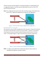
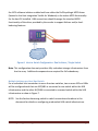
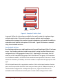
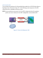
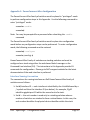
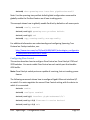
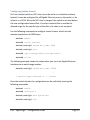
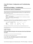
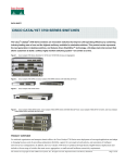
Dell™ EqualLogic™ Configuration Guide A guide to building an iSCSI based SAN solution with Dell™ EqualLogic™ PS Series Arrays January 2009 THIS WHITE PAPER IS FOR INFORMATI/ONAL PURPOSES ONLY, AND MAY CONTAIN TYPOGRAPHICAL ERRORS AND TECHNICAL INACCURACIES. THE CONTENT IS PROVIDED AS IS, WITHOUT EXPRESS OR IMPLIED WARRANTIES OF ANY KIND. Dell and EqualLogic are trademarks of Dell, Inc. Other trademarks and trade names may be used in this document to refer to either the entities claiming the marks and names or their products. Dell disclaims proprietary interest in the marks and names of others. © 2009 Dell Inc. All rights reserved. Reproduction in any manner whatsoever without the express written permission of Dell, Inc. is strictly forbidden. For more information, contact Dell. Dell™ EqualLogic™ Configuration Guide Page i Table of Contents Table of Contents..............................................................................................................ii Introduction ..................................................................................................................... 1 EqualLogic Infrastructure Requirements .......................................................................... 1 Network Configuration and Design Considerations ......................................................... 1 Infrastructure Configuration ............................................................................................ 4 Array to Switch Infrastructure ...................................................................................... 4 Single Switch/Single Array Controller ....................................................................... 4 Single Switch/Dual Array Controller ......................................................................... 5 Dual Switch/Single Array Controller ......................................................................... 5 Dual Switch/Dual Array Controller ........................................................................... 6 Host to Switch Infrastructure ....................................................................................... 7 Single Initiator per Server......................................................................................... 7 Multiple Initiators per Host/Single Switch ................................................................ 7 Multiple Initiators per Host/Dual Switch .................................................................. 8 Switch to Switch Connections ...................................................................................... 9 Stackable Switches ................................................................................................... 9 Non-Stackable Switches ......................................................................................... 10 Putting It All Together ................................................................................................ 11 Fully Redundant SAN .............................................................................................. 12 Partially Redundant SAN Configurations ................................................................ 13 Appendix A: General Requirements for Switches When Used with EqualLogic PS Series Arrays ............................................................................................................................ 16 Appendix B: PowerConnect 54xx Configuration ............................................................ 18 Disabling iSCSI Optimization Setting .......................................................................... 19 Dell™ EqualLogic™ Configuration Guide Page ii Enabling the PortFast Option to Configure STP Edge Ports ........................................ 19 Configuring Flow Control ........................................................................................... 20 Configuring Storm Control ......................................................................................... 20 Configuring Jumbo Frames......................................................................................... 21 Appendix C: PowerConnecct 62xx Configuration .......................................................... 22 Interface Naming Convention .................................................................................... 22 Enabling the PortFast Option to Configure STP Edge Ports ........................................ 23 Configuring Flow Control ........................................................................................... 23 Configuring Storm Control ......................................................................................... 24 Configuring Jumbo Frames......................................................................................... 25 Appendix D: Cisco IOS Based Switch Configuration ....................................................... 26 Enabling the PortFast Option to Configure STP Edge Ports ........................................ 27 Configuring Flow Control ........................................................................................... 28 Disabling Unicast Storm Control ................................................................................ 29 Configuring Jumbo Frames......................................................................................... 30 Dell™ EqualLogic™ Configuration Guide Page iii Introduction The Dell™ EqualLogic™ Configuration Guide is provided as an aid to help storage administrators determine how best to build an iSCSI infrastructure for use within an EqualLogic SAN solution. This document will focus on configuration best practices, connection rules, general switch configuration parameters, and other helpful information. This document should not be considered a statement of support for any specific configuration. Actual viability of any configuration will depend on the capabilities of the individual components (switches, initiators, etc.) that make up the SAN infrastructure. This document should be used strictly as a guide in planning an EqualLogic SAN solution. EqualLogic Infrastructure Requirements Dell recommends Cisco and PowerConnect 5400 and 6200- series switches for use with EqualLogic arrays. Configuration guidance for these switches is provided in the Appendix of this document. Dell will support any switch infrastructure component within an EqualLogic SAN solution assuming it meets minimum standards (Defined in Appendix A) required to support high-performance iSCSI traffic. Dell will provide full support to resolve customer issues within the SAN solution. If an infrastructure component is identified as causing an issue, the customer may be required to directly contact that component vendor for further support. Network Configuration and Design Considerations Each control module has three network interface ports, labeled eth0, eth1, and eth2. A dual control module array provides three pairs of network interfaces. For example, eth0 on Control Module 0 (CM0) and eth0 on Control Module 1(CM1) is a pair. Only one port in a pair is active for I/O at one time. All ports are considered active on a single controller at a time. Dell™ EqualLogic™ Configuration Guide Page 1 In addition to the requirements and recommendations described in the following tables, all the usual rules for proper network configuration apply to the group members. General network configuration is beyond the scope of this document. Requirement At least one network connection Description An array must have at least one functioning network interface connected to a network (through a network switch, if possible). When you run the setup utility, you will assign an IP address and subnet mask to this interface. Connectivity to group IP address Each array must have at least one functioning network interface that is on the same subnet as the group IP address. Switch connectivity In a single-subnet group in which the arrays are connected to multiple switches, there must be network connectivity between the switches. Flow Control enabled on Enable Flow Control on each switch port that handles iSCSI traffic. If your server is using a software iSCSI initiator and NIC combination to handle iSCSI traffic, you switches and NICs must also enable Flow Control on the NICs to obtain any performance benefit. PS Series storage arrays will correctly respond to Flow Control. Table 1: Network Requirements Dell™ EqualLogic™ Configuration Guide Page 2 Recommendation Redundant network Paths Description Using a multi-pathing solution helps to ensure that no single point of failure exists between hosts and arrays. MPIO implementations should be available for most modern operating system environments. For replication, a reliable, adequately sized network link For effective and predictable replication, be sure that the network link between the primary and secondary groups is reliable and provides sufficient bandwidth for copying data. No STP functionality on switch ports that connect end nodes Do not use Spanning-Tree (STP) on switch ports that connect end nodes (iSCSI initiators or storage array network interfaces). However, if you want to use STP or Rapid STP (preferable to STP), you should enable the port settings available on some switches that let the port immediately transition into STP forwarding state upon link up. This functionality can reduce network interruptions that occur when devices restart, and should only be enabled on switch ports that connect end nodes. Note: The use of Spanning-Tree when using multiple independent single-cable connection between switches is encouraged. Note: Using native Link Aggregation “trunking” functionality between non-stacking switches rather than multiple, independent, single-cable connections is highly encouraged. Jumbo Frames enabled on switches and NICs Enable Jumbo Frames on each switch that handles iSCSI traffic. If your server is using a software iSCSI initiator and NIC combination, you must also enable Jumbo Frames on the NICs that handle iSCSI traffic to obtain any performance benefit and ensure consistent behavior. VLANs Configure switches to use VLANs in order to separate iSCSI SAN traffic from other network traffic. Switched Gigabit Ethernet network Connect arrays and hosts to a switched network and ensure that all network connections between hosts and arrays are Gigabit Ethernet. An array can operate at 10 and 100 Mbps, but performance will be significantly degraded. Access to the group IP address In a multi-subnet group, each configured network interface should have access to the subnet on which the group IP address resides. Multiple network Connections Connect multiple network interfaces on an array (to different switches, if possible). You can configure the interfaces (assign an IP address and subnet mask) after adding the array to the group. Unicast Storm Control Disabled unicast storm control on on each switch that handles iSCSI traffic. Table 2: Network Recommendations Dell™ EqualLogic™ Configuration Guide Page 3 Infrastructure Configuration Dell recommends that all EqualLogic SAN solutions be configured for full redundancy. The following table identifies all opportunities for redundancy: Component Hosts SAN Switches EqualLogic Array Redundant Configuration Two or more network interface ports attached to the SAN. Each port should be connected to a different switch within the SAN. MPIO software solution enabled for redundancy Two or more switches configured for inter-switch communications with standard ports for uplink or stacked using proprietary stacking technology. Each array should have at least one port from each controller connected to each switch. Table 3: Redundancy Definitions Based on these definitions, the following sections will further define the connection recommendations for the primary component connections within the SAN infrastructure. While full redundancy in all SAN components is recommended, nonredundant connections are provided for those situations where full redundancy is not viable. Array to Switch Infrastructure Single Switch/Single Array Controller Single controller arrays can connect to one or more switches within the SAN infrastructure. For the single array controller/single switch solution, one, two or more array controller ports should be connected to the switch as illustrated in Figure 1. These connections must not be aggregated in any way. Note: This configuration does not provide a fully redundant storage infrastructure from host to array. Additional components are required for full redundancy. Dell™ EqualLogic™ Configuration Guide Page 4 CM0 Stackable Switch 0 EqualLogic™ Figure 1: Single Controller Array to Single Switch Configuration Single Switch/Dual Array Controller For dual controller arrays connecting to a single Ethernet switch, one, two or more ports from controller CM0 should be connected to the switch. In addition, at least one port from array controller CM1 should also be connected to the switch. All three ports from CM1 can be connected to the switch to ensure that there is no performance decrease if there is a failure in CM0. This will provide a redundant path to the array should an array controller fail as shown in Figure 2. Stackable Switch 0 CM0 CM1 Note: This configuration does not provide a fully redundant storage infrastructure from host to array. Additional components are required for full redundancy. EqualLogic™ Figure 2: Dual Controller Array to Single Switch Configuration Dual Switch/Single Array Controller Single controller arrays can be connected to redundant switches as shown in Figure 3. Ensure that at least one port from CM0 is connected to the second switch. The two Dell™ EqualLogic™ Configuration Guide Page 5 switches must be connected together via stacking connections or uplinking ports that are aggregated together to provide equivalent bandwidth based on the active CM0 ports connected to the SAN. Note: This configuration does not provide a fully redundant storage infrastructure from host to array. Additional components are required for full redundancy. Stackable Switch 0 CM0 Stacking Connection Stackable Switch 1 EqualLogic™ Figure 3: Dual Controller Array to Single Switch Configuration Dual Switch/Dual Array Controller Stackable Switch 0 CM0 Stacking Connection Stackable Switch 1 CM1 Dual controller arrays should be configured such that two ports on Controller 0 attach to one switch and the third port connects to a second switch. Two ports on Controller 1 should connect to the second switch and the third port should connect to the first switch. The complete diagram in Figure 4 illustrates this connection requirement. EqualLogic™ Figure 4: Dual Controller Array/ Dual Switch Configuration NOTE: It is highly recommended that all components and connections within an EqualLogic SAN should be redundant in nature. Dell™ EqualLogic™ Configuration Guide Page 6 Host to Switch Infrastructure Host computers should be configured with one or more network interface controllers (NICs) dedicated to iSCSI SAN communications or with one or more iSCSI host bus adapters (HBAs). If NICs are used for iSCSI communications, a supported softwarebased iSCSI initiator will be required. Most modern operating systems in use today provide software iSCSI initiators. If one is not available, then an iSCSI HBA will be required to connect the host to the iSCSI SAN. NOTE: It is highly recommended that all components and connections within an EqualLogic SAN should be redundant in nature. Single Initiator per Server In a non-redundant host connection solution, a single NIC or HBA will be connected to one switch within the SAN infrastructure as illustrated in Figure 5. iSCSI Server Note: This configuration does not provide a fully redundant storage infrastructure from host to array. Additional components are required for full redundancy. NIC 0 NIC 1 Switch 0 Corporate LAN Figure 5: Host to Switch Configuration- Single Initiator/Single Switch Multiple Initiators per Host/Single Switch Redundant host solutions will incorporate two or more NICs or HBAs connected to one or more SAN switches. For hosts connecting to a single switch SAN, each NIC or HBA should be connected to the SAN switch as illustrated in Figure 6. Each NIC should have Dell™ EqualLogic™ Configuration Guide Page 7 Server iSCSI MPIO the iSCSI software initiator enabled and have either the Dell EqualLogic MPIO driver (located in the Host Integration Toolkit for Windows) or the native MPIO functionality for the host OS installed. HBA connections should leverage the standard MPIO functionality of the driver provided by the vendor to support failover and/or loadbalancing features. NIC 2 NIC 3 NIC 1 NIC 0 Switch 0 Corporate LAN Figure 6: Host to Switch Configuration- Dual Initiator / Single Switch Note: This configuration does not provide a fully redundant storage infrastructure from host to array. Additional components are required for full redundancy. Multiple Initiators per Host/Dual Switch For a redundant host connection to more than two switches, two or more NICs or HBAs will be configured such that one NIC/HBA is connected to one switch within the SAN infrastructure and the other NIC/HBA is connected to a second switch within the SAN infrastructure as show in Figure 7. NOTE: See the Section discussing switch to switch connections elsewhere in this document for details on configuring a redundant SAN switch infrastructure. Dell™ EqualLogic™ Configuration Guide Page 8 iSCSI NIC 2 NIC 3 NIC 1 NIC 0 Stacking Connection Server MPIO Stackable Switch 1 Stackable Switch 0 Corporate LAN Figure 7: Single Controller Array to Switch Configuration When multiple NICs or HBAs are configured to support redundant host connections to the iSCSI SAN, the iSCSI initiators must be configured to support connection failover (and potentially load balancing) using industry standard Multi-Path Input/Output (MPIO) functionality. The steps to configure MPIO and the level of MPIO functionality are different for each operating system, so please consult your operating system documentation for further information. Switch to Switch Connections Stackable Switches Stackable switches provide dedicated, high-bandwidth ports that connect switches together into either a bus, or more typically, loop architecture. High-bandwidth, interswitch connectivity is an important factor in the overall performance of an EqualLogic SAN allowing the individual arrays to coordinate SAN activities and to allow data to be balanced between multiple arrays. Dell™ EqualLogic™ Configuration Guide Page 9 I I I Stackable Switch 0 Stackable Switch 1 Stackable Switch 2 O O O Stacking Port Stacking Cable Figure 8: Example: 3 Switch Stack In general, follow the instructions provided by the switch vendor for implementing a multiple-switch stack. If the switch vendor supports multiple stack topologies, implement the topology that provides the most redundancy and provides the ability to expand the stack without interruption of SAN traffic. Figure 8 illustrates an example using three stackable switches. Non-Stackable Switches Non-Stacking switches are a viable solution only for small EqualLogic SANs of 3 or fewer arrays. Non-stacking switches should be connected by using standard Ethernet ports configured into a Link Aggregation Group (LAG). Depending on the vendor, this will either be a LACP-compliant link group or an EtherChannel® link group. If the switches are of different vendors, LACP will be the standards-based protocol to be used. Please follow the directions provided by the switch vendor to implement the appropriate LAG type. All LAGs should consist of an equivalent number of links to the total number of active ports on all arrays within the SAN. Each array can have up to 3x 1Gbps active ports, so LAG should be configured for 3x 1Gbps links per array. Figure 9 illustrates a nonstackable switch infrastructure with 4 ports on each switch configured into a LAG. Dell™ EqualLogic™ Configuration Guide Page 10 Non-Stacking Switch 1 Non-Stacking Switch 0 Ethernet Port Ethernet Cable LACP Aggregation/EtherChannel® Figure 9: Example: 4-port Aggregated Uplink Putting It All Together Based on the previous discussions focusing on the three main infrastructure component connections - hosts, arrays, and switches, the following set of diagrams illustrate a set of redundant and non-redundant SAN configurations with all of the components combined into a complete set of solutions. Dell™ EqualLogic™ Configuration Guide Page 11 Fully Redundant SAN The only design that addresses all of the possible failure modes for an iSCSI SAN that utilizes an EqualLogic array is illustrated in Figure 10. In this SAN design, each component of the SAN infrastructure has a redundant connection or path. NIC 3 Switch 0 CM0 iSCSI NIC 2 NIC 0 Stack or Uplink Server MPIO Switch 1 NIC 1 CM1 NOTE: For any production environment, this is the ONLY configuration that will completely protect your access to data and is the ONLY configuration recommended by Dell. EqualLogic™ Corporate LAN Figure 10: End-to-End Redundant SAN Dell™ EqualLogic™ Configuration Guide Page 12 Partially Redundant SAN Configurations Though each of the SAN designs below will allow each host to access its data within the SAN, these are not recommended for production deployment, and should not be interpreted as a recommendation, as they do not provide a fully redundant SAN solution. NIC 0 NIC 1 Switch 0 CM0 iSCSI Server Single Array Controllers Configurations EqualLogic™ Corporate LAN iSCSI NIC 2 NIC 3 NIC 1 NIC 0 Switch 0 CM0 Server MPIO Figure 11: Single Switch/Single NIC EqualLogic™ Corporate LAN Figure 12: Single Switch/Dual NIC Dell™ EqualLogic™ Configuration Guide Page 13 NIC 3 NIC 0 Switch 0 CM0 iSCSI NIC 2 Stack or Uplink Server MPIO Switch 1 NIC 1 EqualLogic™ Corporate LAN Figure 13: Dual Switch/Dual NIC NIC 0 NIC 1 Switch 0 CM0 iSCSI Server CM1 Dual Array Controllers Configurations EqualLogic™ Corporate LAN Figure 14: Single Switch/Single NIC Dell™ EqualLogic™ Configuration Guide Page 14 NIC 0 NIC 1 Switch 0 CM1 CM0 Stack or Uplink iSCSI MPIO Server Switch 1 EqualLogic™ Corporate LAN NIC 3 CM1 iSCSI NIC 2 NIC 1 NIC 0 Switch 0 CM0 Server MPIO Figure 15: Dual Switch/Single NIC EqualLogic™ Corporate LAN Figure 16: Single Switch/Dual NIC Dell™ EqualLogic™ Configuration Guide Page 15 Appendix A: General Requirements for Switches When Used with EqualLogic PS Series Arrays For a switch to provide reliable operation within a Dell EqualLogic SAN infrastructure, the following features must be available: Non-Blocking backplane design A switch should be able to provide the same amount of backplane bandwidth to support full duplex communication on ALL ports simultaneously. Support for Inter-Switch Linking (ISL) or Dedicated Stacking Architecture ISL support is required to link all switches in SAN infrastructure together. For non-stacking switches, the switch should support designating one or more (through Link Aggregation Groups) ports for inter-switch links. For stacking switches, the use of stacking ports for ISL is assumed. Switch should provide at least 20Mbps full-duplex bandwidth. Support for creating Link Aggregation Groups (LAG) For non-stacking switches, the ability to bind multiple physical ports into a single logical link for use as an ISL is required. Switch should support creating LAGs of at least 8x 1Gbps ports or at least 1x 10Gbps port. Note: Non-stacking switches with more than three EqualLogic Arrays could exhibit some performance reduction. Support for active or passive Flow Control (802.3x) on ALL ports. Switches must be able to actively manage “pause” frames received from hosts, or they must passively pass all “pause” frames through to the target arrays. Support for Rapid Spanning Tree Protocol (R-STP) Dell™ EqualLogic™ Configuration Guide Page 16 For SAN infrastructures consisting of more than 2 non-stacking switches, RSTP must be enabled on all ports used for ISLs. All non-ISL ports should be marked as “edge” ports or set to “portfast”. Support for Jumbo Frames Not a requirement, but desirable. Many storage implementations can take advantage of Jumbo Frames. Jumbo frames may not provide any performance increases depending on the application and data characteristics. Ability to disable Unicast Storm Control iSCSI in general, and Dell EqualLogic SANs in particular can send packets in a very “bursty” profile that many switches mis-diagnose as a viral induced packet storm. Since the SAN should be isolated from general Ethernet traffic, the viral possibilities are non-existent. Switches need to always pass Ethernet packets regardless of bandwidth utilization. Adequate Buffer Space per switch port The Dell EqualLogic SAN solution makes use of the SAN infrastructure to support inter-array communication and data load balancing on top of supporting data transfers between the hosts and the SAN. For this reason, the more buffer space per port that a switch can provide the better. Due to the multitude of buffer implementations used by switch vendors, Dell cannot provide definitive guidelines as to how much is enough, but this should not be an issue for most Enterprise-class switch vendor’s solutions. Dell™ EqualLogic™ Configuration Guide Page 17 Appendix B: PowerConnect 54xx Configuration The PowerConnect 54xx Family of switches must be placed in “privileged” mode to perform configuration steps in this Appendix. Use the following command to enter “privileged” mode: console> enable console# Note: You may be prompted for a password after submitting the enable command The PowerConnect 54xx Family of switches must be place into configuration mode before any configuration steps can be performed. To enter configuration mode, the following command must be entered: console# configure console(config)# PowerConnect 54xx Family of switches are non-stacking switches and must be configured independently using either the web-based Switch manager or the Command Line Interface (CLI). The instructions in this Appendix provide CLI commands for configuration. Please go to Dell’s support website for the latest documentation if the web-interface is preferred. Port references for the PowerConnect 54xx switch must use the interface command and the port references are in the form of “g”+<port#>. For example, Port 10 on the Powerconnect 5424 would be referenced as console(config)# interface ethernet g10 To reference a range of ports, the interface range command must be used with the port reference in the form of “g(“+<begport#> + “-“ + <endport#>+ “)”. For example, to reference all ports between port g1 and port g15 would be referenced as console(config)# interface range ethernet g(1-15) Dell™ EqualLogic™ Configuration Guide Page 18 Disabling iSCSI Optimization Setting The PowerConnect 54xx family of switches has a global feature called “iSCSI Optimization” that is designed to configure the Quality of Service settings to allow iSCSI frames to have priority over other frame types within the switch. The settings used when this command is enabled are designed to optimize an iSCSI storage solution consisting of a single iSCSI storage device and is not optimal for a SAN consisting of multiple EqualLogic PS Series arrays in a peer storage configuration and must be disabled for switches used within a PS Series SAN. To disable the iSCSI Optimization settings for the PowerConnect 54xx family of switches, perform the following steps: console# configure console(config)# no iscsi enable console(config)# exit console# copy running-config startup-config console# exit Enabling the PortFast Option to Configure STP Edge Ports To enable PortFast on a single port, the spanning-tree portfast command must be used. PortFast should be enabled only on those ports being used to for interswitch connections. The following steps are an example of using this command to enable portfast on port 10 of the PowerConnect 5448 console# configure console(config)# spanning-tree mode rstp console(config)# interface ethernet g10 console(config-if)# spanning-tree portfast console(config-if)# exit console(config)# exit Dell™ EqualLogic™ Configuration Guide Page 19 console# copy running-config startup-config console# exit Configuring Flow Control Flow control on the PowerConnect 54xx Family of switches is off by default. To enable flow control on all ports in the switch, use the system flowcontrol command. Flow control only works when the port is in full duplex mode, so be sure to enable full duplex on the port before enabling flow control To enable flow control on all ports of a PowerConnect 5448, enter the following commands: console# configure console(config)# interface range ethernet g(1-48) console(config-if)# speed 1000 console(config-if)# duplex full console(config-if)# flowcontrol on console(config-if)# exit console(config)# exit console# copy running-config startup-config console# exit Configuring Storm Control To disable port storm control on the PowerConnect 54xx switch, use the no port storm-control broadcast enable command. The following steps are an example of using this command to disable storm control on a single port of a PowerConnect 5448 switch: console# configure console(config)# interface Ethernet g1 console(config-if)# no port storm-control broadcast enable Dell™ EqualLogic™ Configuration Guide Page 20 console(config-if)# exit console(config)# exit console# copy running-config startup-config console# exit The following steps are an example of how to disable storm control on all ports of a PowerConnect 5448 switch: console# configure console(config)# interface range ethernet all console(config-if)# no port storm-control broadcast enable console(config-if)# exit console(config)# exit console# copy running-config startup-config console# exit Configuring Jumbo Frames Jumbo frames are not enabled by default. To enable jumbo frames on the PowerConnect 54xx switch, use the port jumbo-frame global configuration command. Jumbo frames are enabled on all ports on a switch when enabled. console# configure console(config)# port jumbo-frame console(config)# exit console# copy running-config startup-config console# exit Dell™ EqualLogic™ Configuration Guide Page 21 Appendix C: PowerConnecct 62xx Configuration The PowerConnect 62xx Family of switches must be placed in “privileged” mode to perform configuration steps in this Appendix. Use the following command to enter “privileged” mode: console> enable console# Note: You may be prompted for a password after submitting the enable command The PowerConnect 62xx Family of switches must be place into configuration mode before any configuration steps can be performed. To enter configuration mode, the following command must be entered: console# configure console(config)# PowerConnect 62xx Family of switches are stacking switches and must be configured as a stack using either the web-based Switch manager or the Command Line Interface (CLI). The instructions in this Appendix provide CLI commands for configuration. Please go to Dell’s support website for the latest documentation if the web-interface is preferred. Interface Naming Convention The conventions for naming interfaces on Dell PowerConnect 62xx family of switches are as follows: Unit#/Interface ID — each interface is identified by the Unit# followed by a / symbol and then the Interface ID (see below). For example, 2/g10 identifies gigabit port 10 within the second unit of a stack. Unit# — the unit number is used only in a stacking solution where a number of switches are stacked to form a virtual device. In this case, the unit number identifies the physical device identifier within the stack. Dell™ EqualLogic™ Configuration Guide Page 22 Interface ID — is formed by the interface type followed by the interface number. There is currently a predefined list of interface types (see below). If additional interface types are to be defined, they must be registered with Dell. For example, 2/g10 identifies the gigabit port 10 on the second unit. Interface Types — the following interface types are defined in the 6200 series switches: g — gigabit Ethernet port (for example, 1/g2 is the gigabit Ethernet port 2). • xg — 10 Gigabit Ethernet port (for example, 1/xg2 is the 10 gigabit Ethernet port 2). Enabling the PortFast Option to Configure STP Edge Ports To enable PortFast on a single port, the spanning-tree portfast command must be used. The following steps are an example of using this command to enable portfast on port 10 of the first PowerConnect 6248 in a stack console# configure console(config)# spanning-tree mode rstp console(config)# interface ethernet 1/g10 console(config-if)# spanning-tree portfast console(config-if)# exit console(config)# exit console# copy running-config startup-config console# exit Configuring Flow Control Flow control on the PowerConnect 62xx Family of switches is off by default. To enable flow control on all ports in the switch, use the flowcontrol command. To enable flow control on all ports of a PowerConnect 6248, enter the following commands: console# configure Dell™ EqualLogic™ Configuration Guide Page 23 console(config)# flowcontrol console(config)# exit console# copy running-config startup-config console# exit Configuring Storm Control To disable port storm control on the PowerConnect 62xx switch, use the no storm-control unicast command. The following steps are an example of using this command to disable the unicast storm control on a single port – Port 10 of Switch 3 in a stack: console# configure console(config)# interface ethernet 3/g10 console(config-if)# no storm-control unicast console(config-if)# exit console(config)# exit console# copy running-config startup-config console# exit The following steps are an example of how to disable unicast storm control on all ports in a PowerConnect 62xx switch stack: console# configure console(config)# interface range ethernet all console(config-if)# no storm-control unicast console(config-if)# exit console(config)# exit console# copy running-config startup-config console# exit Dell™ EqualLogic™ Configuration Guide Page 24 Configuring Jumbo Frames Jumbo frames are not enabled by default. To enable jumbo frames on the Powerconnect 62xx switch, use the mtu interface configuration command with a parameter of 9216. Because the mtu command is an interface configuration command, each port must be individually configured with the mtu command. All ports on a switch can be configured using the port range command. console# configure console(config)# interface range ethernet all console(config-if)# mtu 9216 console(config-if)# exit console(config)# exit console# copy running-config startup-config console# exit Dell™ EqualLogic™ Configuration Guide Page 25 Appendix D: Cisco IOS Based Switch Configuration Cisco IOS based switches must be placed in “privileged” mode to perform configuration steps in this Appendix. Use the following command to enter “privileged” mode: Switch> enable Switch# Cisco IOS based switches must be place into configuration mode before any configuration steps can be performed. To enter configuration mode, the following command must be entered: Switch# configure terminal To configure a port on non-chassis based Cisco IOS switch, the interface type, stack member number, module number, and switch port number must be provided, and enter interface configuration mode. • Interface Type—Gigabit Ethernet and small form-factor pluggable (SFP) modules(gigabitethernet or gi), 10-Gigabit Ethernet (tengigabitethernet or te). • Stack member number—Identifies the switch within the stack. The switch number range is 1 to 9 and is assigned the first time the switch initializes. All standalone switches have stack member number equal to 1. When a switch is added to an existing stack it will receive a new stack member number and it keeps that number until another is assigned to it. Non-Stackable switches have a stack member number of 1. The switch port LEDs can be configured in Stack mode to identify the stack member number of a switch. • Module number—The module or slot number on the switch is always 0. • Port number—Reflects the actual port number on the switch. Port numbers always begin at 1, starting with the far left port when facing the front of the switch. Dell™ EqualLogic™ Configuration Guide Page 26 For switches that have Cisco TwinGig Converter Modules in 10-Gigabit Ethernet module slots, the interface type is tengigabitethernet, and the port numbers restart at 1. For example, the first port on the first TwinGig Converter Module is referenced as tengigabitethernet1/0/1 and the first port on the second TwinGig Converter Module would be referenced as tengigabitethernet1/0/3. For switches that are using Cisco dual SFP X2 converter modules in the 10Gigabit Ethernet module slots, the SFP module ports are numbered consecutively following the fixed port interfaces. For example, if the switch has 24 fixed ports, the SFP module ports are gigabitethernet1/0/25 through gigabitethernet1/0/28. A Catalsyt® 3750-E example: Port 4 is idenetified by entering the following command: Switch(config)# interface gigabitethernet1/0/4 Enabling the PortFast Option to Configure STP Edge Ports To configure STP edge ports on Cisco IOS-based switches, the Portfast option must be set on the desired port(s). The following example shows how to enable PortFast on Gigabit Ethernet interface 0/1 on switch 1: Switch> enable Switch# configigure terminal Switch(config)# interface gi1/0/1 Switch(config-if)# spanning-tree portfast Switch(config-if)# exit Switch(config)# exit Switch# copy running-config startup-config To view or confirm Port Fast status on a port, use the following command. Dell™ EqualLogic™ Configuration Guide Page 27 Switch# show spanning-tree interface gigabitethernet0/1 Note: Use the spanning-tree portfast default global configuration command to globally enable the PortFast feature on all non-trunking ports. This example shows how to globally enable PortFast by default on all access ports: Switch# config terminal Switch(config)# spanning-tree portfast default Switch(config)# end Switch# copy running-config startup-config For additional information on understanding and configuring Spanning-Tree Protocol on Catalyst switches, see: http://www.cisco.com/en/US/tech/tk389/tk621/technologies_configuratio n_example09186a008009467c.shtml Configuring Flow Control This section describes how to configure Flow Control on Cisco Catalyst 3750 and 2970switches. You must enable Flow Control on each switch port that handles iSCSI traffic. Note: Cisco Catalyst switch ports are capable of receiving, but not sending, pause frames. The following commands shows how to configure Gigabit Ethernet interface 0/1 on switch 1 to auto-negotiate the correct Flow Control setting with the device to which it is connected: Switch> enable Switch# configure terminal Switch(config)# interface gigabitethernet1/0/1 Switch(config-if)# flowcontrol receive desired Switch(config-if)# exit Dell™ EqualLogic™ Configuration Guide Page 28 Switch(config)# exit Switch# copy running-config startup-config To view or confirm Flow Control status on a port, use the following command: Switch# show flowcontrol interface gigabitethernet1/0/1 Disabling Unicast Storm Control This section describes how to disable unicast storm control on Cisco Catalyst 3750 and 2970 switches. The following example shows how to disable unicast storm control on Gigabit Ethernet interface 0/15 on switch 1 and verify the configuration: Switch> enable Switch# configure terminal Switch(config)# interface gigabitethernet1/0/15 Switch(config-if)# no storm-control unicast level Switch(config-if)# exit Switch(config)# exit Switch# copy running-config startup-config To view or confirm storm control status on a port, use the following command. Switch# show storm-control gigabitethernet1/0/15 unicast Interface Filter state Level Current --------- ------------ ----------Gi2/0/15 Inactive 100.00% N/A For more information on configuring port-based traffic control on Catalyst switches, see: http://www.cisco.com/en/US/products/hw/switches/ps5023/products_configura tion_guide_chapter09186a008021272b.html Dell™ EqualLogic™ Configuration Guide Page 29 Configuring Jumbo Frames On Cisco Catalyst switches, MTU size cannot be set for an individual interface. Instead, it must be configured for all Gigabit Ethernet ports on the switch, or for all ports in a VLAN. When the MTU size is changed, the switch must reset before the new configuration takes effect. If a value is entered that is outside the allowed range for the specific type of interface, the value is not accepted. Use the following commands to configure Jumbo Frames, which sets the maximum packet size to 9000 bytes: Switch> enable Switch# config terminal Switch(config)# system mtu jumbo 9000 Switch(config)# exit Switch# copy running-config startup-config Switch# reload The following example shows the output when you try to set Gigabit Ethernet interfaces to an outof-range number: Switch(config)# system mtu jumbo 25000 ^ % Invalid input detected at '^' marker. Once the switch reloads, the configuration can be verified by entering the following commands: Switch> enable Switch# configure t Switch(config)# show system mtu Switch(config)# exit Dell™ EqualLogic™ Configuration Guide Page 30 The commands shown next are used to enable an individual VLAN to use Jumbo Frames. Note that VLAN1 cannot have Jumbo Frames enabled. VLAN 2 must be used if Jumbo Frames are required. Switch# vlan database Switch(vlan)# vlan 2 mtu 9000 Switch(vlan)# exit To view or confirm MTU size on port 7 of the switch, use the following command. Switch# show interface gigabitethernet1/0/7 For more information on configuring Jumbo Frames or Giant Frames on Catalyst switches, see: http://www.cisco.com/en/US/products/hw/switches/ps700/products_configurati on_example09186a008010edab.shtml Dell™ EqualLogic™ Configuration Guide Page 31