1
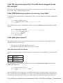
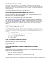
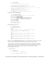
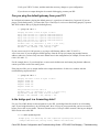
Cisco DSL Router Configuration and Troubleshooting
Guide
RFC1483 Pure Bridging – Troubleshooting
Determine the Layer to Troubleshoot
There are many reasons why your Digital Subscriber Line (DSL) connection may not be functioning properly.
The goal of this section is to isolate the cause of the failure and repair it. The first troubleshooting step is to
determine which layer of your Asymetric Digital Subscriber Line (ADSL) service is failing. There are three
layers in which the failure can occur.
• Layer 1 – DSL physical connectivity to your ISP's Digital Subscriber Line Access Multiplexer
(DSLAM)
• Layer 2.1 – ATM connectivity
• Layer 2.2 – Point−to−Point Protocol over ATM (PPPoA), Point−to−Point Protocol over Ethernet
(PPPoE), RFC1483 Bridging, or RFC1483 Routing
• Layer 3 – IP
The easiest way to determine which layer you should begin troubleshooting is to issue the command show ip
interface brief. The output of this command differs slightly depending on your configuration.
827−ESC#show ip interface brief
Interface
IP−Address
OK?
ATM0
unassigned
YES
ATM0.1
unassigned
YES
Ethernet0
10.10.10.1
YES
Method
Status
manual up
unset
up
manual
up
Protocol
up
up
up
If the statuses of ATM0 and ATM0.1 are up and the protocol is up, begin troubleshooting at Layer 2.
If the ATM interfaces are down, or if they keep coming up and then going down (they don't stay up), begin
troubleshooting at Layer 1.
Layer 1 Issues
Is the carrier detect (CD) light on the front panel of the Cisco DSL Router
on or off?
If the CD light is on, go to the Layer 2 Issues section of this document.
If the CD light is off, continue with the next question.
Is your ISP using a DSLAM that supports the Alcatel chipset?
Verify this information with your ISP.
Cisco DSL Router Configuration and Troubleshooting Guide − RFC1483 Pure Bridging – Troubleshooting
Is the DSL port on the back of the Cisco DSL Router plugged into the
DSL wall jack?
If the DSL port is not plugged into the DSL wall jack, connect the port to the wall with a 4−pin or 6−pin
RJ−11 cable. This is a standard telephone cable.
Is the ATM interface in an administratively down state?
To determine if the ATM0 interface is administratively down, issue the following command in enable mode
on the router:
Router#show interface atm 0
ATM0 is administratively down, line protocol is down
<... snipped ...>
If the ATM0 interface status is administratively down, issue the no shutdown command under the ATM0
interface.
Router#configigure terminal
Enter configuration commands, one per line. End with CNTL/Z.
Router(config)#interface atm 0
Router(config−if)#no shut
Router(config−if)#end
Router#write memory
Is the cable pinout correct?
If the ATM0 interface status is down and down, the router is not seeing a carrier on the ADSL line. This
generally indicates one of two issues:
1. The active pins on the DSL wall jack are incorrect.
2. Your ISP has not turned up a DSL service on this wall jack.
Cisco DSL Router xDSL Port Pinouts
The RJ−11 connector provides an xDSL connection to external media via a standard RJ−11 6−pin modular
jack.
Pin
Description
3
XDSL_Tip
4
XDSL_Ring
To determine if the ATM0 interface is down and down, issue the show interface atm 0 command from
enable mode of the router.
Router#show interface atm 0
ATM0 is down, line protocol is down
<... snipped ...>
If the ATM interface is down and down—not administratively down—check the pinout of your DSL wall
jack. The DSL Router uses a standard RJ−11 (4−pin or 6−pin) cable to provide the ADSL connection to the
wall jack. The center pair of pins on the RJ−11 cable is used to carry the ADSL signal (pins 3 and 4 on a
Cisco DSL Router Configuration and Troubleshooting Guide − RFC1483 Pure Bridging – Troubleshooting
6−pin cable, or pins 2 and 3 on a 4− pin cable).
If you are sure you have the right pins on the wall jack and the ATM0 interface is still down and down,
replace the RJ−11 cable between the DSL port and your wall jack. If the interface is still down and down after
replacing the RJ−11 cable, contact your ISP and have the ISP verify that DSL service has been enabled on the
wall jack you are using.
If you are not sure what pins on your wall jack are active, ask your ISP.
Do you have the correct power supply for the Cisco 827?
If you have verified that your ADSL cable is good and that you have the correct pinouts, the next step is to
make sure you have the correct power supply for the 827.
Note: The 827 does not use the same power supply as other 800 series routers.
To determine if you have the correct power supply, on the back of the power adapter look for Output +12V
0.1A, −12V 0.1A, +5V 3A, −24V 0.12A, and −71V 0.12A. If your power supply is missing the +12V and
−12V feeds, then it is for a different Cisco 800 series router and will not work on the 827. Note that if you use
the wrong power supply, the Cisco 827 will power up but will be unable to train up (connect) to the ISP
DSLAM.
Is the DSL operating−mode correct?
If everything up to this point in the Layer 1 troubleshooting procedure is correct, the next step is to make sure
you have the correct DSL operating mode. Cisco recommends using dsl operating−mode auto if you are not
sure what DMT technology your ISP is using. The commands to configure operating−mode autodetection are
as follows:
Router#configure terminal
Enter configuration commands, one per line.
Router(config)#interface atm 0
Router(config−if)#dsl operating−mode auto
Router(config−if)#end
Router#write memory
End with CNTL/Z.
Is the circuit tested/provisioned correctly?
Obtain this information from your ISP or telephone company.
Layer 2 Issues
Do you have the correct Permanent Virtual Circuit (PVC) values
(VPI/VCI)?
Complete the following steps to determine whether you have the correct virtual path identifier/virtual circuit
identifier (VPI/VCI) values configured on the router.
1. Verify your version of Cisco IOS® software.
Important: This will not work with Cisco IOS Software Release 12.1(1)XB.
Cisco DSL Router Configuration and Troubleshooting Guide − RFC1483 Pure Bridging – Troubleshooting
Router#show version
!−−− Used to determine your Cisco IOS version.
Cisco Internetwork Operating System Software
IOS (tm) C820 Software (C820−OSY656I−M), Version 12.1(3)XG3,
EARLY DEPLOYMENT RELEASE SOFTWARE (fc1)
!−−− The two lines immediately preceding appear on one line on the router.
TAC:Home:SW:IOS:Specials for info
Copyright (c) 1986−2000 by cisco Systems, Inc.
Compiled Wed 20−Dec−00 16:44 by detang
Image text−base: 0x80013170, data−base: 0x80725044
<... snipped ...>
2. Configure the router for debug logging.
Router#configure terminal
Enter configuration commands, one per line. End with CNTL/Z.
Router(config)#logging console
Router(config)#logging buffer
Router(config)#service timestamp debug datetime msec
Router(config)#service timestamp log datetime msec
Router(config)#end
Router#write memory
Building configuration...
[OK]
Router#terminal monitor
3. Enable debugging on the router.
Router#debug atm events
ATM events debugging is on
Router#
2d18h:
2d18h: RX interrupt: conid =
2d18h: Data Cell received on
!−−− Your VPI/VCI.
2d18h:
2d18h: RX interrupt: conid =
2d18h: Data Cell received on
2d18h:
2d18h: RX interrupt: conid =
2d18h: Data Cell received on
2d18h:
2d18h: RX interrupt: conid =
2d18h: Data Cell received on
0, rxBd = 0x80C7EF74 length=52
vpi = 8 vci = 35
0, rxBd = 0x80C7EEC0 length=52
vpi = 8 vci = 35
0, rxBd = 0x80C7EECC length=52
vpi = 8 vci = 35
0, rxBd = 0x80C7EED8 length=52
vpi = 8 vci = 35
4. Make sure you have debug ATM events running on the Cisco DSL Router, and then go to a working
Internet connection and begin to ping the IP address your ISP statically assigned to you.
It does not matter whether you have configured this IP address on the Cisco DSL Router. What is
important is that your ATM interface is up/up and that you are pinging the IP address your ISP gave
you. If you don't see the expected output after the ping test, contact your ISP for support.
5. Disable debugging on the router.
<< wait 60 seconds >>
Router#undebug all
!−−− Used to turn off the debug events.
All possible debugging has been turned off.
Cisco DSL Router Configuration and Troubleshooting Guide − RFC1483 Pure Bridging – Troubleshooting
Verify your VPI/VCI values, and then make the necessary changes to your configuration.
If you do not see output during the 60 seconds of debugging, contact your ISP.
Can you ping the default gateway from your PC?
In a bridged environment, pinging the default gateway is a good test of connectivity. In general, if you can
ping to your default gateway, you know that Layer 1 and Layer 2 services are functioning properly. Open an
MS−DOS window and try to ping the default gateway.
C:\>ping 192.168.1.1
Pinging 192.168.1.1 with 32 bytes of data:
Reply from 192.168.1.1: bytes=32 time<10ms TTL=247
Reply from 192.168.1.1: bytes=32 time<10ms TTL=247
Reply from 192.168.1.1: bytes=32 time<10ms TTL=247
Reply from 192.168.1.1: bytes=32 time<10ms TTL=247
Ping statistics for 192.168.1.1:
Packets: Sent = 4, Received = 4, Lost = 0 (0% loss),
Approximate round trip times in milli−seconds:
Minimum = 0ms, Maximum = 0ms, Average = 0ms
If your success rate is 80−100 percent, try to ping a valid Internet address (198.133.219.25 is
www.cisco.com). If you can ping the default gateway from the PC but you cannot ping another Internet
address, make sure you have only one static default route in the configuration (for example, IP route 0.0.0.0
0.0.0.0 192.168.1.1).
For the example above, if you already have a correct static default route and cannot ping Internet addresses,
contact your ISP to resolve the routing issue.
If the ping test fails, you see output similar to the output shown below. In this case, continue with the
troubleshooting steps that follow.
C:\>ping 192.168.1.1
Pinging
Request
Request
Request
Request
192.168.1.1 with 32 bytes of data:
timed out.
timed out.
timed out.
timed out.
Ping statistics for 192.168.1.1:
Packets: Sent = 4, Received = 0, Lost = 4 (100% loss),
Approximate round trip times in milli−seconds:
Minimum = 0ms, Maximum = 0ms, Average = 0ms
Is the bridge port in a forwarding state?
For your Cisco DSL Router to forward packets to your ISP, your bridged interface must be in a forwarding
state. If your bridged interface is in a blocking state, there is a loop in your network that you have to remove
before you are able to pass traffic. The most common cause of a loop in a DSL network is having two bridged
DSL circuits to the same ISP.
Router#show spanning−tree
Bridge group 1 is executing the ieee compatible Spanning Tree protocol
Bridge Identifier has priority 32768, address 0001.96a4.a8bc
Cisco DSL Router Configuration and Troubleshooting Guide − RFC1483 Pure Bridging – Troubleshooting
Configured hello time 2, max age 20, forward delay 15
Current root has priority 32768, address 0000.0c25.36f4
Root port is 3 (ATM0), cost of root path is 1562
Topology change flag not set, detected flag not set
Number of topology changes 2 last change occurred 00:00:56 ago from Ethernet0
Times: hold 1, topology change 35, notification 2
hello 2, max age 20, forward delay 15
Timers: hello 0, topology change 0, notification 0, aging 300
Port 2 (Ethernet0) of Bridge group 1 is forwarding
Port path cost 100, Port priority 128, Port Identifier 128.2.
Designated root has priority 32768, address 0000.0c25.36f4
Designated bridge has priority 32768, address 0001.96a4.a8bc
Designated port id is 128.2, designated path cost 1562
Timers: message age 0, forward delay 0, hold 0
Number of transitions to forwarding state: 1
BPDU: sent 44, received 0
Port 3 (ATM0) of Bridge group 1 is forwarding
Port path cost 1562, Port priority 128, Port Identifier 128.3.
Designated root has priority 32768, address 0000.0c25.36f4
Designated bridge has priority 32768, address 0000.0c25.36f4
Designated port id is 128.17, designated path cost 0
Timers: message age 2, forward delay 0, hold 0
Number of transitions to forwarding state: 1
BPDU: sent 2, received 53
Router#
Is there an entry in the bridge table?
When you are sure that your bridged interface is forwarding, you need to determine if you have the Layer 2
media access control (MAC) address of your ISP's gateway router. Use the show bridge command to check
for the Layer 2 address. This command lists all the Layer 2 entries for a specific bridge group.
In the following example, there are two entries in the bridge table. The first entry is the MAC address of the
PC client in the LAN. The second entry is the MAC address of the ISP's gateway router (default gateway). If
the MAC address of the ISP's gateway router is not in the bridge table, contact your ISP to verify your
network settings.
Router#show bridge
Total of 300 station blocks, 298 free
Codes: P − permanent, S − self
Bridge Group 1:
Address
0010.a492.e1d2
0010.7bb9.bd1a
Action
forward
forward
Interface
Ethernet0
ATM0
Age
4
0
RX count
163
4
TX count
4
3
Router#
Related Information
• Cisco DSL Technology Support Information
• Cisco DSL Product Support Information
• Technical Support − Cisco Systems
Cisco DSL Router Configuration and Troubleshooting Guide − RFC1483 Pure Bridging – Troubleshooting
Contact the Cisco Technical Assistance Center
If you need additional assistance implementing RFC1483 pure bridging, contact the Cisco Technical
Assistance Center (TAC).
Note: To use the Case Open tool to open a case online, you must be a registered user and you must be logged
in.
Call the TAC
If you do not have a service contract with Cisco and need assistance implementing RFC1483 pure bridging,
direct your web browser to Cisco's Warranty Status Tool.
Cisco DSL Router– RFC1483 Pure Bridging Page
Main
Page
All contents are Copyright © 1992−−2003 Cisco Systems Inc. All rights reserved. Important Notices and Privacy Statement.
Updated: Aug 24, 2006
Document ID: 71129
Cisco DSL Router Configuration and Troubleshooting Guide − RFC1483 Pure Bridging – Troubleshooting