1
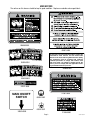
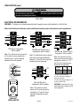
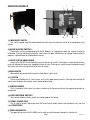
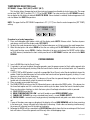
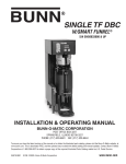
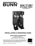
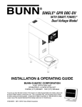
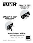
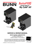
SINGLE TF DBC
W/SMART FUNNEL®
S/N SNG0033000 & UP
INSTALLATION & OPERATING GUIDE
BUNN-O-MATIC CORPORATION
POST OFFICE BOX 3227
SPRINGFIELD, ILLINOIS 62708-3227
PHONE: (217) 529-6601 FAX: (217) 529-6644
To ensure you have the latest revision of the manual or to obtain the illustrated parts catalog, please visit
the Bunn-O-Matic website, at www.bunn.com. This is absolutely FREE, and the quickest way to obtain
the latest catalog and manual updates. Contact Bunn-O-Matic Corporation at 1-800-286-6070 to obtain
a paper copy of the required Illustrated Parts Catalog mailed via U.S. Postal Service.
35879.0002A
03/12 ©2012 Bunn-O-Matic Corporation
BUNN-O-MATIC COMMERCIAL PRODUCT WARRANTY
Bunn-O-Matic Corp. (“BUNN”) warrants equipment manufactured by it as follows:
1) Airpots, thermal carafes, decanters, GPR servers, iced tea/coffee dispensers, MCP/MCA pod brewers thermal servers
and Thermofresh servers (mechanical and digital)- 1 year parts and 1 year labor.
2) All other equipment - 2 years parts and 1 year labor plus added warranties as specified below:
a) Electronic circuit and/or control boards - parts and labor for 3 years.
b) Compressors on refrigeration equipment - 5 years parts and 1 year labor.
c) Grinding burrs on coffee grinding equipment to grind coffee to meet original factory screen sieve analysis - parts
and labor for 4 years or 40,000 pounds of coffee, whichever comes first.
These warranty periods run from the date of installation BUNN warrants that the equipment manufactured by it will be
commercially free of defects in material and workmanship existing at the time of manufacture and appearing within the
applicable warranty period. This warranty does not apply to any equipment, component or part that was not manufactured
by BUNN or that, in BUNN’s judgment, has been affected by misuse, neglect, alteration, improper installation or operation,
improper maintenance or repair, non periodic cleaning and descaling, equipment failures related to poor water quality,
damage or casualty. In addition, the warranty does not apply to replacement of items subject to normal use including but
not limited to user replaceable parts such as seals and gaskets. This warranty is conditioned on the Buyer 1) giving BUNN
prompt notice of any claim to be made under this warranty by telephone at (217) 529-6601 or by writing to Post Office
Box 3227, Springfield, Illinois 62708-3227; 2) if requested by BUNN, shipping the defective equipment prepaid to an
authorized BUNN service location; and 3) receiving prior authorization from BUNN that the defective equipment is under
warranty.
THE FOREGOING WARRANTY IS EXCLUSIVE AND IS IN LIEU OF ANY OTHER WARRANTY, WRITTEN OR ORAL, EXPRESS OR IMPLIED, INCLUDING, BUT NOT LIMITED TO, ANY IMPLIED WARRANTY OF EITHER MERCHANTABILITY
OR FITNESS FOR A PARTICULAR PURPOSE. The agents, dealers or employees of BUNN are not authorized to make
modifications to this warranty or to make additional warranties that are binding on BUNN. Accordingly, statements by such
individuals, whether oral or written, do not constitute warranties and should not be relied upon.
If BUNN determines in its sole discretion that the equipment does not conform to the warranty, BUNN, at its exclusive option while the equipment is under warranty, shall either 1) provide at no charge replacement parts and/or labor (during the
applicable parts and labor warranty periods specified above) to repair the defective components, provided that this repair
is done by a BUNN Authorized Service Representative; or 2) shall replace the equipment or refund the purchase price for
the equipment.
THE BUYER’S REMEDY AGAINST BUNN FOR THE BREACH OF ANY OBLIGATION ARISING OUT OF THE SALE OF THIS
EQUIPMENT, WHETHER DERIVED FROM WARRANTY OR OTHERWISE, SHALL BE LIMITED, AT BUNN’S SOLE OPTION
AS SPECIFIED HEREIN, TO REPAIR, REPLACEMENT OR REFUND.
In no event shall BUNN be liable for any other damage or loss, including, but not limited to, lost profits, lost sales, loss of
use of equipment, claims of Buyer’s customers, cost of capital, cost of down time, cost of substitute equipment, facilities
or services, or any other special, incidental or consequential damages.
392, AutoPOD, AXIOM, BrewLOGIC, BrewMETER, Brew Better Not Bitter, BrewWISE, BrewWIZARD, BUNN Espress, BUNN
Family Gourmet, BUNN Gourmet, BUNN Pour-O-Matic, BUNN, BUNN with the stylized red line, BUNNlink, Bunn-OMatic,
Bunn-O-Matic, BUNNserve, BUNNSERVE with the stylized wrench design, Cool Froth, DBC, Dr. Brew stylized Dr. design,
Dual, Easy Pour, EasyClear, EasyGard, FlavorGard, Gourmet Ice, Gourmet Juice, High Intensity, iMIX, Infusion Series, Intellisteam, My Café, Phase Brew, PowerLogic, Quality Beverage Equipment Worldwide, Respect Earth, Respect Earth with
the stylized leaf and coffee cherry design, Safety-Fresh, savemycoffee.com, Scale-Pro, Silver Series, Single, Smart Funnel,
Smart Hopper, SmartWAVE, Soft Heat, SplashGard, The Mark of Quality in Beverage Equipment Worldwide, ThermoFresh,
Titan, trifecta, Velocity Brew, A Partner You Can Count On, Air Brew, Air Infusion, Beverage Bar Creator, Beverage Profit
Calculator, Brew better, not bitter., BUNNSource, Coffee At Its Best, Cyclonic Heating System, Daypart, Digital Brewer
Control, Nothing Brews Like a BUNN, Pouring Profits, Signature Series, Tea At Its Best, The Horizontal Red Line, Ultra are
either trademarks or registered trademarks of Bunn-O-Matic Corporation.
INTRODUCTION
The brewer incorporates a wireless interface system that allows the DBC Grinder to load certain information into the
"programming chip" located inside the handle of the funnel. This information includes what flavor of coffee is being
ground and what batch size will be brewed (small, medium, or large). Once the correct flavor name and amount of
coffee is ground, the funnel is loaded into the brewer. The information from the funnel handle is then transferred into
the brewer. The brewer then takes this information and dispenses the amount of water preset in the brewer for that
particular flavor of coffee and batch size. The brewer can also be programmed to adjust different functions of the
brewing process, such as brew temperature, brew volumes, bypass percentages, pulse brew, etc. This allows the
operator to program a certain "recipe" for each coffee flavor to be brewed.
Page 2
35879.2 030912
USER NOTICES
The notices on this brewer should be kept in good condition. Replace unreadable or damaged labels.
00658.0000
00831.0000
As directed in the International Plumbing Code of the
International Code Council and the Food Code
Manual of the Food and Drug Administration (FDA),
this equipment must be installed with adequate
backflow prevention to comply with federal, state
and local codes. For models installed outside the
U.S.A., you must comply with the applicable Plumbing /Sanitation Code for your area.
03408.0004
#00656.0001
03409.0004
20201.5600
MAIN ON/OFF
SWITCH
39803.0000
37881.0000
00824.0002
00824.0001
27508.0000
Page 3
35879.2 031512
USER NOTICES (cont.)
To reduce the risk of electric shock,
do not remove or open cover.
No user-serviceable parts inside.
Authorized service personnel only.
Disconnect power before servicing.
37881.0002
ELECTRICAL REQUIREMENTS
WARNING - The brewer must be disconnected from the power source until specified in Initial Set-Up.
Refer to Data Plate on the Brewer, and local/national electrical codes to determine circuit requirements.
L2 RED
WHITE
WHITE
NEUTRAL
L1 BLACK
NEUTRAL
L1 BLACK
GREEN
GREEN
N
L1
G
WHITE
L2 RED
WHITE
L2
WHITE
NEUTRAL
L1 BLACK
N
NEUTRAL
L1 BLACK
GREEN
L1
GREEN
G
NEUTRAL
L1 BLACK
L2 RED
L3 BLUE
GREEN
120 volt ac single phase,
60 Hz models
Note: This electrical service consists
of 2 current carrying conductors
(Neutral and L1) and a separate
conductor for earth ground.
120/208 and 120/240 volt ac
single phase, 60 Hz models
Note: This electrical service consists
of 3 current carrying conductors
(Neutral, L1 and L2) and a separate
conductor for earth ground.
BACK
WHITE
200 or
230V
L1 BLACK
BLUE
L2 RED
WHITE/VIOLET
GREEN
GREEN
FRONT
120/208V
120/240V
120V
DUAL VOLT
TOGGLE SWITCH
200 and 230 volt ac
single phase, 60 Hz models
Note: This electrical service
consists of 2 current carrying
conductors (L1 and L2) and a
separate conductor for earth
ground.
Page 4
GREEN
120/208 and 120/240 volt ac
three phase, 50 Hz models
Note: This electrical service
consists of 4 current carrying
conductors (Neutral, L1, L2
and L3) and a separate conductor for earth ground.
SYSTEM
VOLTAGE
208
240
V1
V2
208 120
240 120
L1, L2, L3, are the 3 phases
V1 = Phase to phase voltage, between any 2 phases.
V2 = Phase to neutral voltage, L1 to
neutral must be 120V.
CAUTION: Do not connect L1 to a
circuit operating at more than 150
volts to ground.
35879.2 031512
ELECTRICAL REQUIREMENTS (cont.)
ELECTRICAL HOOK-UP
WARNING – If brewer is equipped with a power cord and it is ever damaged, it must be replaced by the manufacturer or authorized service personel with a special cord available from the manufacturer or its authorized
service personel in order to avoid a hazard. Improper electrical installation will damage electronic components.
Damage caused by incorrect electrical connections is not covered by warranty.
1. An electrician must provide electrical service.
2. Using a voltmeter, check the voltage and color coding of each conductor at the electrical source.
NOTE - Brewers shipped with a power cord are shipped without a plug on it. Qualified service personnel
must select and install the proper UL listed grounding type attachment plug specified on the rear of the
brewer.
3. Install the specified plug on the attached power cord.
4. Remove the access panel beneath the sprayheads to gain access to the terminal block.
5. Brewers not equipped with a power cord, feed the wire through the strain relief and connect it to the terminal block.
6. Using the above diagrams, connect the desired electrical service to the field wiring terminal block.
7. If wiring the machine for operation on 120/208 or 120/240 volts with a Power Supply Cord, the Power
Supply Cord must be UL Listed Flexible Cord Type SO, SJO, SJTO, HSJO or SJOW, No. 12 AWG, 4 Conductor, Rated 90° C. Attachment Plug Cap must be UL Listed, NEMA 14-20P or L14-20P Configuration,
Rated 125/250V, 20 AMPS. The Power Supply Cord must be at least 3 feet long and maximum 6 feet long
(measured from Strain Relief to end of the Attachment Plug Cap).
8. Connect the brewer to the power source and verify the voltage at the terminal block before proceeding.
9. Set toggle switch on component bracket to the appropriate position and replace the access panel.
10.If plumbing is to be hooked up later be sure the brewer is disconnected from the power source. If plumbing has been hooked up, the brewer is ready for Initial Set-Up.
WARNING – Electrical connections must be made as specified above. Failure to follow these instructions can
result in personal injury, property or equipment damage.
Page 5
35879.2 031512
CE REQUIREMENTS
• This appliance must be installed in locations where it can be overseen by trained personnel.
• For proper operation, this appliance must be installed where the temperature is between 5°C to 35°C.
• Appliance shall not be tilted more than 10° for safe operation.
• An electrician must provide electrical service as specified in conformance with all local and national codes.
• This appliance must not be cleaned by water jet.
• This appliance is not intended for use by persons (including children) with reduced physical, sensory or mental
capabilities, or lack of experience and knowledge, unless they have been given instructions concerning use of
this appliance by a person responsible for its safety.
• Children should be supervised to ensure they do not play with the appliance.
• If the power cord is ever damaged, it must be replaced by the manufacturer or authorized service personnel with
a special cord available from the manufacturer or its authorized service personnel in order to avoid a hazard.
PLUMBING REQUIREMENTS
This brewer must be connected to a cold water system with operating pressure between 20 and 90 psi (138 and 620
kPa) from a 1⁄2" or larger supply line. A shut-off valve should be installed in the line before the brewer. Install a regulator
in the line when pressure is greater than 90 psi (620 kPa) to reduce it to 50 psi (345 kPa). The water inlet fitting is 3⁄8" flare
or female quick connect.
NOTE – Bunn-O-Matic recommends 3⁄8" copper tubing for all installations from the 1⁄2" water supply line. A tight coil of
copper tubing in the water line will facilitate moving the brewer to clean the counter top. Bunn-O-Matic does not recommend the use of a saddle valve to install the brewer. The size and shape of the hole made in the supply line by this type
of device may restrict water flow.
As directed in the International Plumbing Code of the International Code Council and the Food Code
Manual of the Food and Drug Administration (FDA), this equipment must be installed with adequate
backflow prevention to comply with federal, state and local codes. For models installed outside the
U.S.A., you must comply with the applicable Plumbing /Sanitation Code for your area.
PLUMBING HOOK-UP
NOTE - If a backflow preventer is required by code, a shock arrestor should be installed between backflow preventer and dispenser. Installing the shock arrestor as close to dispenser as possible will provide best results.
1. Flush the water line and securely attach it to the flare fitting located on bottom of brewer.
2. Turn on the water supply.
Page 6
35879.2 031512
OPERATING CONTROLSf
j
f
e
d
h
g
b
a
c
P2725
(a) MAIN ON/OFF SWITCH
This switch, located under the brewer behind the front leg, turns power on and off to all components in the
brewer.
(b) BATCH SELECTOR SWITCHES
Pressing the switch corresponding to the Small, Medium, or Large batch selects the amount of coffee to
be brewed. Pressing a different switch after a brew cycle has been initiated does not change the brew batch in
progress. Light indicates the selected batch to brew.
(c) ON/OFF SWITCH (ENABLE BREW)
Pressing the ON/OFF switch alternately turns the brewer on and off. Pressing this switch during the brew
cycle will interrupt the brew cycle, stopping the flow of water. Pressing this switch during the programming of
the brewer will exit the setup and return to the main screen.
(d) BREW SWITCH
Momentarily pressing and releasing this switch begins a brew cycle.
(e) ® SWITCH
Pressing and holding the ® switch allows entry to the programming menus. Pressing and releasing the
switch steps through each function screen during programming.
(f) FUNCTION SCREEN
This is the display which shows the various functions of the brewer and allows the programming to be accomplished.
(g) FUNCTION SCREEN SWITCHES
These are the hidden switches which are used to program the brewer.
(h) FUNNEL SENSING COILS
This is used to "receive" information from the Smart Funnel handle (coffee name and batch size), and also
from RECIPE CARDS.
(j) SCROLL BACKWARDS
The upper left corner of the B in BUNN can be used to scroll backwards through the function list.
Page 7
35879.2 031512
INITIAL SETUP
CAUTION – The brewer must be disconnected from the power source throughout the initial setup, except when
specified in the instructions.
1. Insert an empty funnel into the funnel rails of the brew station.
2. Place an empty server under the funnel.
3. Connect the brewer to the power source. Water will begin
flowing into the tank and stop when the tank is filled to its
capacity. Display will show PLEASE WAIT...TANK FILLING
until tank is filled with water.
4. Wait approximately 20 mins for the water in the tank to
heat to the proper temperature on 120V/208V machines.
(Wait approximately 45 mins on 120V machines). Display
will show READY TO BREW...WATER TEMP: XXX˚ when
tank is at operating temperature.
NOTE: Brew water temperature is factory set at 205° F (96.1°
C). Refer to TEMPERATURE SELECTION below should the
water temperature need to be increased or decreased. When
brew water temperature is changed, ready temperature
should be increased or decreased accordingly.
5. Place a small vessel beneath the faucet and open the faucet
handle. Release it when you hear the tank refilling.
6. Water volumes have been preset at the factory. Refer
to adjustments for the Set Brew Volumes section of the
Programming Manual on the Bunn-O-Matic website, at
www.bunn.com should the volume need to be increased
or decreased.
7. The brewer is now ready for use in accordance with the coffee brewing instructions.
TEMPERATURE SELECTION
SET TEMP - Range: 185˚F (85˚C) to 205˚F (96˚C)
This function allows the operator to set the brew water temperature in the tank. It also sets the hot water
faucet dispense temperature.
SET TEMP: XXX°
(-) DONE (+)
Procedure to set brew temperature:
1. Press and hold upper right hidden switch until the display reads UNITS. Release switch. Continue to press
and release switch until the display reads SET TEMP.
2. To adjust the brew temperature, press (-) to decrease or (+) to increase the brew temperature.
3. When finished, press and release DONE to save the new setting, exit the SET TEMP function and advance to
the next function screen, SET READY. Another alternative is to press and release the ON/OFF switch (either
on DUAL brewers) located on the front switch panel to exit the SET TEMP function and return to the MAIN
SCREEN.
Page 8
35879.2 031512
TEMPERATURE SELECTION (cont)
SET READY - Range: 185˚F (85˚C) to 203˚F (95˚C)
This function allows the operator to set the minimum temperature allowable to start a brew cycle. The range
can be from 185˚F (85˚C) to within 2˚F (-1.7°C) of the SET TEMP. The water must be at the SET READY temperature or higher for the display to indicate READY TO BREW. If brew lockout is enabled, the brewing process will
not start below this READY temperature.
NOTE: The upper limit for SET READY temperature is 2˚F (-1.7°C) less than the water temperature (SET TEMP)
setting.
SET READY: XXX°
(-) DONE (+)
Procedure to set ready temperature:
1. Press and hold upper right hidden switch until the display reads UNITS. Release switch. Continue to press
and release switch until the display reads SET READY.
2. To adjust the ready temperature, press the (-) button to decrease, or (+) to increase the ready temperature.
3. When finished, press and release DONE to save the new setting, exit the SET READY function and advance
to the next function screen, REFILL. Another alternative is to press and release the ON/OFF switch (either
on DUAL brewers) located on the front switch panel to exit the SET READY function and return to the MAIN
SCREEN.
COFFEE BREWING
1. Insert a BUNN filter into the Smart Funnel.
2. If a grinder is not used to obtain the coffee grounds, pour the proper amount of fresh coffee grounds into
the funnel and level by gently shaking. Slide the funnel into the funnel rails and select batch size. Proceed to
step 5.
3. If a G9-2T DBC or MHG grinder is used with a compatible Smart Funnel, select the desired batch size on the
grinder. Grind the selected amount of fresh coffee into funnel and level grounds by gently shaking. It is not
necessary to select a size on the brewer.
4. Slide the funnel into the funnel rails. The brewer will read the size ground through the chip in the funnel
handle and will automatically select the correct size to brew.
5. Place an empty server under the funnel.
6 The ENABLE BREW switch must be ON. Momentarily press and release the BREW switch. If the brewer has
the funnel lock option and if it is activated, once a brew cycle has been started the funnel is locked in place.
There may be certain situations in which the brew cycle will not begin when brew switch is pressed:
a) ENABLE BREW must be ON.
b)
BREW TEMPERATURE TOO LOW - wait until heated or cancel BREW LOCKOUT option.
c) FUNNEL NOT IN PLACE (or using a standard brew funnel) - cancel FUNNEL DETECT.
d)
CHECK FUNNEL - remove funnel, empty previously brewed grounds and grind a new batch into the funnel.
7. If none of the above messages are displayed, the display will read NOW BREWING and the time remaining
in the brew cycle. Arrows will point to the side which is brewing. If both sides are brewing simultaneously,
the arrows will alternate from left to right on the display.
8. Following the BREW will be a countdown of DRIPPING time which shows the time remaining until the funnel
lock will release. Discard the grounds and filter only after visible dripping stops.
Page 9
35879.2 031512
CLEANING
1. The use of a damp cloth rinsed in any mild, nonabrasive, liquid detergent is recommended for cleaning all
surfaces on Bunn-O-Matic equipment. Do NOT clean this equipment with a water jet device.
2. Check and clean each sprayhead. The sprayhead holes must always remain open.
NOTE: Any buildup on the sprayhead and fitting may restrict water flow, and impact your coffee brewing. For
consistently great coffee, clean sprayheads and fittings weekly with sprayhead cleaning tool (#38227.0000).
Upon visual inspection it may appear that light passes through all holes in the sprayhead plate, but a thin
film of residue can pass light and still impede water flow.
3. Insert the long end of sprayhead cleaning tool into the sprayhead fittings, and rotate several times to remove
any mineral deposits from the fitting.
4. Insert the short end of sprayhead cleaning tool into the bypass fittings, and rotate several times to remove
any mineral deposits from the fitting.
5. Remove sprayheads from brewer. Disassemble by removing the seal.
6. Use the pointed end of sprayhead cleaning tool to remove any mineral deposits from the sprayhead holes.
7. Reassemble sprayheads and reattach. Sprayheads only needs to be hand tightened.
Refer to Programming Manual on the Bunn-O-Matic website, at www.bunn.com for calibration routine to verify
sprayhead flow rate matches programmed flow rate. Machine may need to be re-calibrated due to lime build
up. If machine is cleaned and build up removed, machine must be re-calibrated to achieve desired volumes.
Page 10
35879.2 031512