1
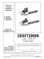
Scars ]
owner's
manual
®
®
•
®
Assembly
Operation
Maintenance
Repair Parts
MODEL NO.
358.354830.3.7/18"
358.354870-3.7/18"P5
3.7/18" 3.7/18"PS
CHAIN SAWS
Record in the space provided below the Model No. and Serial No,, of
your saw, These numbers are located on the starting instructions
decal,
WARNING:
Carefully
read and follow
Safety Rules, Precautions
and Operating Instructions°
Failure to do so can result
in serious personal injury.
Sears,
Model No
Serial No.
Retain these numbers
Roebuck
and
Co.,
Cl_ioa_o,
for future reference
Ill. 6068.4
U.S,A.
u,
PRINTED IN U, S. A,
64754-3-08383-1-(}8383
FULL ONE YEAR WARRANTY ON GASOLINE CHAIN SAW
(Excluding Bar, Chain, Spark Plug, Air Filter and Starter Rope)
For one year from date of
and maintenance
instructions
chain saw at no charge
in the owner s manual,
Sears wtlt repair defects
in material
or workmanship
in this gasoline
_:_
This warranty excludes the bar, chain, spark plug, air filter, and starter rope which are expendable
parts and become worn
during normal use
if this chain saw is used for commercial
or rental purposes, this warranty applies for only 30 days from date of purchase.
WARRANTY SERVICE IS AVAILABLE
BY RETURNING THE CHAIN SAW TO THE NEAREST SEARS STORE OR SERVICE
CENTER IN THE UNITED STATES
This warranty
gives you specific
legal rights,
and you may also have other rights which vary from state to stale
Sears Roebuck and Co Sears Tower Dept 698/73tA
Chicago
IL 60684
TABL
OF ©@NT NT$
Specifications
.................................
Safety Rules and Precautions ....................
Know Your Chain Saw .........................
A, Introduction
...........................
B, State and Local Ordinances
...............
C. Carton Contents .......................................
Preparing Your Saw For Use .....................
A., Getting Ready ..........................
B, Attaching the Handguard
.................
C, Attaching the Spur .............................
D, Attaching the Bar and Chain ...................
E. Chain Tension ............................
Fo Engine Fuel Mixture ......................
G. Bar and Chain Oil .........................
Using Your Saw ..................................
A. Control Devices
B, Starting Instructions
.....................
C Controlling
Kickback ...........................
2
3
4
4
4
4
5
5
5
5
6
7
7
8
9
9
g
10
...........................
Using The Power Sharp System ...................
Types of Cutting ......................................
Ao Basic Cutting Technique ....................
B. Tree Felling Techniques ..................
C. Bucking .................................
Dr Debranching and Pruning ......................
Maintenance
A. Guide Bar and Chain .....................
B. Ignition, Cooling, and Exhaust Systems .....
Co Starter Rope Repairand Replacement ......
D. Clutch, Drum and Sprocket .................
E. Carburetor Adjustments
.....................
F. Air Filter .....................................
G, Counter-Vibe TM Vibration System .............
H, Storage ......................................
1, Maintenance Accessories
................
J, Trouble Shooting Chart ....................
Parts List
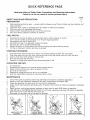
Quick Reference Page ...........................
..................................
......................................
.....
11
13
13
13
t4
!5
16
16
18
19
20
21
22
22
22
22
23
24
31
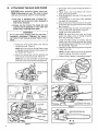
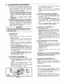
SPE©WFU©ATla@N$
MODEL
358.354830
CU_iN_DISPLACEMENT
3.7 cu. in.t60 cu.cm.
3,7 cu. tn,160 cu,cm,
18" Sprocket Nose
318 Extended Pitch
Chrome Cutters
18" Sprocket
Nose
318 Extended Pitch
Power Sharp
Chrome Cutters
GUIDE BAR--LO
CHAIN,GUARD
SPARK
KICK
LINK
PLUG
Solid
AiR GAP
,008
FUEL MIX
(3.71i8"
P.S.)
' '
'
Spark Arresling
Slate
to ,0t4
Gasoline/Oil
MUFFLER
Mixture
16:1
Temperature
OILER SYSTEM
Aulomatic
FUEL TANK CAPACITY
_9OZ.562cu: Cm:
OIL TANK CAPACITY
12 OZ. 355 cu. cm.
Li"'iting,,
" '
Manual
HANDGUARD
POWER SHARP ADJUSTING
KNOB (MODEL °354870)
AIR FILTER
COVER
3UARD
THROTTLE
LOCKOUT
CHAIN TENSION
GUARD
LINK
MANUAL
STARTER HANDLE
CHAIN
OILER
THROTTLE
SPUR
LATCH
SWITCH
CHOKE"
OIL
LO KICK GUIDE
THROTTLE
358.354870
Champion
CJ,8Y
.023 to ,027
SPARK PLUG GAP
IGNrflON
MODULE
(3.7118")
TRIGGER
FRONT CHAIN CATCHER
BAR
P
REAR
HAIN
CATCHER
SAFETY
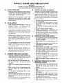
RULES AND PRECAUTIONS
Failure to observe the following
Safety Rules and
WARNING!
Precautions could result
in serious personal injury.
Am
KNOW
YOUR
SAW
D#
1. Read your Owner's Manual carefully until you
completely understand and can apply all safety rules and operating
instructions
before
attempting to operate the unit.
,
Ba
AHHAD
Keep children, bystanders, and pets out of the
work area. Do not allow other people to be
near the chain saw when starting or operating
the chain saw.
Do not handle or operate a chain saw when
you are fatigued, ill, or upset; or if you have
taken alcohol or drugs/medication.
You must
be in good physical condition and mentally
alert1
,,
54
C=
EN
Plan your sawing operation carefully in advance. Do not start cutting until you have a
clear work area, secure footing, and a planned
retreat path from the falling tree
FUI=L
WiTH
CAUTIOH
1. Eliminate all sources of sparks or flame in the
areas where fuel is mixed, poured, or stored.
There should be no smoking, open flames, or
work that could cause sparks.
2 Mix and store fuel in a well-ventilated
area.
Fm
3.. Mix and store fuel
container,
in an approved,
marked
4 Wipe up all spilled
saw.
fuel before starting
your
5, Move at least 10 feet (3 meters) away from
fuel and fueling
site before starting
the
engine_
6 Do not smoke while handling
operating the saw.
fuel or while
7 Turn the engine off and let your saw coo!
before removing the fuel tank cap and refueling the unit.
8. Let the saw cool in a non-combustible
not on dry leaves, straw, paper, etc
area,
OPI=RATI_
YOUR
SAW' SAFELY
1_ Do not operate a chain saw that is damaged,
improperly adjusted, or not completely and
securely assembled.
2 Do not operate the saw from a ladder or in a
tree,
3_ Keep all parts of your body away from the saw
chain when the engine is running.
4 Cut wood only.
5 Make sure the saw chain is not touching
anything before you start the engine..
6 Use extreme caution when cutting small size
brush and saplings_ Slender material may
catch the saw chain and be whipped toward
you or pull you off balancer
7. Be alert for springback when cutting a limb
that is under tension so you will not be struck
by the timb or saw when the tension in the
wood fibers is released
8 Shut off the engine before setting the saw
down.
Do not attempt to use your saw during bad
weather conditions such as strong wind, rain,
snow, etc. or at night since you would not
have good visibility.
HANDLE
KUCKBACK
1_ Hold the chain saw firmly with both hands.
2o Do not overreach.
3. Do not let the nose of the guide bar contact
the ground, a log, a branch, or any other
obstruction.
4o Cut only with the engine running at full throt.
tie.
5 Do not cut above shoulder height.
6. Follow
manufacturer's
sharpening
and
maintenance instructions for the saw chain.
7. Use the Guard Link Chain, and Lo Kick Guide
Bar that are designed for your saw to reduce
the possibility of kickback.
1 Wear personal protective gear. Always use
safety
footwear;
snug-fitting
clothing;
protective
gloves;
and appropriate
eye,
hearing and head protection devices.
.
AGAnNST
Kickback can lead to dangerous loss of con.
trol of the chain saw and possibly cause
serious
personal injury. Kickback is the upward and backward motion of the guide bar that
occurs when the moving chain contacts an object at the nose of the guide bar To reduce the
hazard of kickback:
Restrict the use of your saw to users who
understand
and follow
the safety
rules,
precautions, and operating instructions found
in this manual.
PLAN
GUARD
IMAIlNTAIIIR
WORKI|NG
t
YOUR SAW
ORDER
ltN GOOD
Have all chain saw service performed by your
Sears Service Center, other than the service
listed in the maintenance section of this
manual°
2 Keep fuel and oil caps, screws and fasteners
tight.
3 Keep the handles dry, clean, and free of oil or
fuel mixture.
4_ Make certain the saw chain stops moving
when the throttle trigger is released. If it does
not, refer to page 21 for correct carburetor
idle adjustment instructions..
5. Stop the saw if the chain strikes a foreign object. Inspect the unit and repair or replace
parts as necessary
G=
CARRY
AHD STORE
YOUR SAW
SAFELY
1 Never carry your saw while climbing. Both
hands are needed for safe climbing
2. Carry the unit with the engine stopped, the
Guide Bar and Chain to the rear, and the Muffler away f_om your body.
3 Carry the saw with Guide Bar and Chain
covered, preferably with an appropriate scabbard°
KNOW
A.
4 Allow your saw to cool completely
before
transporting
in any vehicle or storing in any
enclosure.
5. Drain oil and fuel tank before storing for more
than 30 days.
6 Store in a dry area out of the reach of children
and away from where fuel vapors can reach
an open flame from hot water heaters, fur.
nances, etc.
YOUR CHAroN SAW
INTRODUCTmON
The information
found in this manual will
you properly prepare your chain saw for
understand how to operate your saw safely,
perform maintenance
required to keep your
in good working condition.
Your saw has been designed
and includes the following
standard equipment:
help
use,
and
unit
with safety in mind
safety features as
Handguard
Lo Kick Guide Bar
Guard Link Chain
The chain saw should never be operated unless
these devices are properly installed on the unit.
The Lo Kick Guide Bar and Guard Link Chain
have been designed to reduce the incident of
kickback.
You should
thoroughly
read and
understand the section,"Controlling
Kickback,"
on page 10.
Bm
STATE
AND LOCAL
R_QUmREM_NTS
ORDSNANCE
Your saw is equipped with a temperature
limiting
muffler
and spark arresting
screen
which meets the requirements
of California
Codes 4442 and 4443. All U.S. forest land and the
states of California,
Maine, Washington
and
Oregon
require
many
internal
combustion
engines to be equipped with a spark arrestor
screen and a temperature
limiting muffler by
law.
If you operate a chain saw in a state or locale
where such regulations
exist, you are legally
responsible for maintaining the operating condition of these parts. Failure to do so could sub.
ject you to liability or to a finer Muffler and spark
arrestor maintenance
is found on page 18.
C.
CARTOH
CONTENTS
After you unpack the carton:
1. Check the contents against the list below
2. Examine the items for damage.
3. Notify your Sears Store immedia tely if a part is
missing or damaged,
KEY NO. CARTON
I
2
3
--
CONTENTS:
Power Head
Guide Bar
8 oz, can, 2-Cycle Engine Oil
Loose Parts Bag (not shown)
LOOSE PARTS BAG CONTENTS:
-4
5
6
7
8
9
10
Owners' Manual (not shown)
Handguard
Cap-Handguard
Screws-Handguard
Spur
Screw-Spur
Chain
Scrench
QTY
1
1
1
3
1
2
1
1
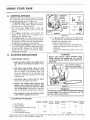
PREPARmH@
A.
GETTmNG
YOUR
SAW
FOR
READY
READ YOUR
OWNER'S
MANUAL
CARE.
FULLY.
Your Owner's Manuat has been developed to
help you prepare your saw for use and to
understand its safe operation_ tt is important
that you read your manual completely
to
become familiar with the unit before you
begin assembly.
B,
ATTACHING
USlE
THE
2. HAVE
THE FOLLOWING
AVAILABLE:
a. Protective gloves
b° Approved, marked fuel container
c. One gallon leaded or unleaded, regular
gasoline
d. Bar and Chain Lubricant (See page 8).
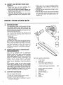
e. Scrench--provided
with your unit No other
tool is necessary for assembly. The tong
end of the tool can be used as a slotted
screwdriver. The small pipe end can be used as a socket wrench., The larger pipe end
can be used to remove the spark plug
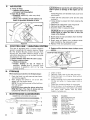
HANDGUARD
The Handguard is a protective device designed
to help prevent your hand from coming in contact with the cutting chain should your hand slip
off the handlebar.
It wilt not eliminate
the
possibility of injury from kickback or loss of control of the saw,
Do not use the saw without the handguard
WARNING!
place°
in
1
® Lift and carry the chain saw by the handlebar
or rear handle, not by the handguard°
e Keep the handguard securely fastened
times_ Check the handguard
screws
time the saw is used
at all
each
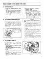
To install:
CAP
I
HANDGUARD
1 Align the Handguard
and Handguard
Cap
around the handlebar as shown in Figure !
/'J_
PIt'_
2 Fit the mounting pin on the Handguard
the hole in the handlebar
Figure 1
3 Insert the 3 mounting screws
on the Handguard Cap
Figure
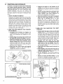
C.
ATTACHING
THE
into
into the 3 holes
Turn each screw a little at a time clockwise,
until the Handguard
Cap and Handguard
meet and there is no gap between the two
parts-
1
SPUR
The spur is a special piece of equipment designed to assist the cutting operation. When
assembfed to the saw, the spur will dig into the
tree or tog and:
--relieve contact pressure adding ease to the
sawing operation.
--allow
the saw to be more easily rotated or
pivoted into the cut.
To Install:
1_ Remove Bar Clamp nuts, Bar Clamp and Guide
Bar Plates,,
2. Align the spur over the two holes on the bar
clamp side of the saw. Figure 2,
31 Insert the two screws and tighten evenly and
securely,
Figure 2
D,
ATTACHRN@
THE
BAR
AND
CHAnN
!CAUTION:IWear
protective gloves when handling or operating your saw. The chain is sharp
and can cut you even when it is not moving!
e Your saw is equipped with a Control Tip
Guide Bar and a Low.Kick chain designed to
help reduce kickback.
e Always use the Control Tip Guide Bar and
Low-Kick Chain designed for your chain saw
model, when replacing these parts=
WARNING!
Do not start engine without guide bar and chain
completely
assembled.
Otherwise
the clutch
can come off and serious personal injury could
result.
ao Install the Inner Guide Plate over the bar
mounting studs Figure&
NOTE: Be sure the Inner Guide Plate curves
or flanges toward the saw frame away from
the Guide Bar, Figure 4.
b. Mount the Guide Bar with the slotted end
over the bar mounting studs, Figure 5.
NOTE: Be sure the Guide Bar is positioned
with the round hole below the large slot,
c,. Hold chain with cutters facing as shown in
Figure 6
d Place chain over and behind the clutch
drum onto the sprocket.,
e_ Slide Guide Bar to the rear of the saw as far
as possible..
f Fit the bottom of the drive links between
the teeth in the sprocket
g, Start at the top of the bar and fit the chain
drive links into the groove around the Guide
Bar. Figure 6.
h, Pull the Guide Bar forward until the chain is
snug in the guide bar groove, Figure 7o
i, install the outer guide plate,
NOTE: Be sure both the inner and outer
guide bar plates curve or flange outward
from the Guide Bar. Figure 4,
j, Install the Bar Clamp by sliding the bar
clamp over the mounting studs and fitting
the bar adjusting pin into the round hole on
the Guide Bar_ Figure 8,
k, Replace the Bar Mounting Nuts and tighten
finger tight only
NOTE: The Bar Clamp nuts must be slightly
loose to tension the chain correctly.
Io Follow "Chain Tension" instructions,
page 7_
Figure 6
Figure 3
OUTER f_
PLATE {0
(1 Slot)
tt
s °s
INNER \_,
PLATE
I_.
Figure 4
ADJUSTING
iTCH
PIN HOLE
Figure 7
BAR
MOUNTING
STUDS
BAR ADJUSTING
GUIDE BAR
Figure 5
6
Figure 8
PIN
Ell
CHAMN TENSUON
2 Check the tension by lifting the chain from
the Guide Bar at the center of the bar, Figure
10,
3, Continue turning the Adjusting
Screw until
the tension is correct.
4, Hold the tip of the Guide Bar up and tighten
the Bar Clamp Nuts with the Scrench
5, Recheck tension,
e Correct chain tension is very important:
--a loose chain will wear the bar and itself,
--a loose chain can jump off the bar while
you are cutting_
--a tight chain can damage the saw andtor
break,
--a chain, either too loose or too tight, can
cause injury,
TURN
Chain tension is correct when the chain:
--can be lifted about 1/8" from the Guide Bar
at a point near the middle of the bar, and
--will move freely around the bar.
TO LOOSEN
TENSION
ADJUSTING
TU RN
SCREW
TO TIGHTEN
TENSION
The chain stretches during use, especially
when new. Check tension:
--each time the saw is used
--more frequently when the chain is new
Figure 9
O
The Bar Clamp Nuts must be slightly loose to
tension the chain correctly.
CHAIN CAN BE
LIFTED 1/8" WHEN
TENSION
IS
CORRECT,,
.
Hold the tip of the Guide Bar up and turn the
Adjusting Screw just until the chain does not
sag beneath the Guide Bar, Figure 9.
118"
NOTE: Turn screw clockwise to tighten tension, Turn screw counterclockwise
to loosen
tension.
Figure 10
F,
ENGgNE
FU_L
MSXTURE
e Your chain saw is powered by a two-cycle
engine which requires a fuel mixture of
regular gasoline and a high quality engine oil
specially
made
for 2.cycle,
air.cooled
engines. The internal design of the 2-cycle
engine requires lubrication
of moving part&
Lubrication
is provided when you use the
recommended
mixture of gasoline and oil,
1, USE THE
@
FUEL MIXTURES:
SEARS #32-36555
! GALLON
REGULAR
GASOLINE
4-
16:1
--OR-ENGINE
OIL
ANY GOOD GRADE
16:1
:_
=
I_
AIR-COOLED, 2-CYCLE
ENGINE OIL
Gasoline must be clean and not over two
months old. After a short period of time,
gasoline begins to chemically
break down
and will form compounds that can cause hard
starting and damage in 2-cycle engines°
The correct measure of gasoline to oil is very
important.
--Too much oil in the mixture wilt foul the
spark plug.
--Too littte oil will cause the engine to overheat resulting in damage.
FOLLOWING
2. DO NOT USE THE
MIXTURES:
._
Oi L
AUTOMOTIVE
ETHYL
GASO
LI NE or
PREMIUg/f
Mix the fuel thoroughly in a container since
gasoline and oil do not readily combine. Do
not try to mix fuel directly in the fuel tank,,
GASOHOL
FOLLOWING
IN FUEL
Does not have proper addi.
fives for 2-cycle engines and
could cause damage
Burns too hot for 2-cycle
engines; will shorten
spark plug life and could
damage your engine
Alcohol absorbs moisture
causing acids to form
which wil! damage metal
and rubber parts
3. HOW
TO MIX FUEL
a,. Pour one-half of the gasoline into an approved, marked container Do not try to mix
oif and gasoline directly in the fuel tank
b Add entire
measure of 2-cycle Engine Oil
c. Mix,
d Add remainder
e, Mix thoroughly
of gasoline
for one minute.
4. IMPORTANT
POINTS
a Use only recommended fuel mixtures.
b, Eliminate all sources of sparks or flame in
the areas where fuel is mixed, poured, or
stored. There should be no smoking, open
flames or work that could cause sparks
c Mix and store fuel in an approved, marked
container.
d. Mix and pour fuel in a well-ventilated
area.
Gasoline vapors are harmful to your health
and are a serious fire hazard
e. Avoid over filling the fuel tank. Allow 3/4
inch for expansion.
Tighten
Fuel Cap
securely
Figure 11
f. Wipe up all fuel spills. Wipe off any fuel
spilled on the saw, Completely dry the saw
before using,,
g. Move at least 10 feet (3 meters) away from
fuel and fueling site before starting the
engine,
Figure 11
G.
RAR AND CHAIIN OliL
e The guide bar and cutting chain require continuous lubrication in order to remain in
operation condition. Lubrication is provided
by the automatic
oiler system when the oil
tank is kept filled.,
--Lack of oil will quickly ruin the bar and
chain.
--Too little oil will cause overheating shown
by smoke coming from the chain and/or
discoloration
of the guide bar rails
1. USE THE
FOLLOWING:
30°F or above -- Lubricant
30OF . 0OF _
95% lubricant to 5% Diesel
Fuel #1 or Kerosene,
Below O°F --
90% lubricant to 10%
Diesel Fuel #I or Kerosene
2, HOW TO FILL THE
O
e
Use SEARS Bar and Chain Lubricant #36554
or clean SAE 30W oil.
In freezing weather oil will thicken, making it
necessary to thin bar and chain oil with a
small amount of Diesel Fuel #1 or Kerosene.
Bar and chain oil must be free flowing for the
oil system to pump enough oiI for adequate
-- undiluted,
OIL TANK
a. Stop the engine.
bl Turn saw on its side with oil cap up Figure
t2
CoLoosen cap slowly and wait for pressure in
the tank to be released before removing the
cap.
d. Fill the oil tank°
Replace the oil cap securely,
3, IMPORTANT
POINTS
TO
REMEMBER
Fill the oil tank each time you refill the fuel
tank to ensure there wil! be sufficient oil for
the chain whenever you start and run the
saw,,
Figure 12
The saw will use about t/2 tank of chain oil
for each tank of fuel mixture. If less oil is
used, check for a plugged oil hole in the
guide bar,
It is normal for a small amount of oil to appear under the saw after the engine stops.
This is due to oil draining from the bar and
chain when not in use
USBN@ Y@UR SAW
A=
COHTROL
THROTTLE
DETENT
BLITTON
DEVBCES
Understanding
the control devices on your saw
is an important part of learning how to properly
and safely operate the unit, Figure 13
t The Ignition Switch is a toggle switch which
is moved up for the "Start" position and moved down for the "Stop" position,
2, The two-position
Choke helps to start the
saw by controlling
the air flow to the fuel
system
3, The Trigger accelerates
and controls
the
speed of the engine and is designed to be
used with the Throttle Lock..
4 The Throttle Lock is a control feature which
prevents the Trigger from becoming accidently engaged, The Throttle Lock must be pressed before the Trigger can be activate&
5,, The Throttle Detent Button holds the Throttle
Lock and Trigger in position while the engine
is being started, Release the Throttle Detent
Button after the engine is started by lightly
squeezing the trigger°
g,
STARTBNG
1. IMPORTANT
C.
PSTA
RT/STOP
/THROTTLE
LOCKOUT
SWITCH
MANUAL
OILER
HALF
OFF
FULL
-!
CHOKE
TRIGGER
Figure 13
6. The Manual Oiler is placed to be operated by
your right thumb, Use the manual oiler to supplement the automatic oiler:
--during
a long felling cut
--when cutting into a log or tree which is
greater in diameter than the length of the
guide bar.
wanytime
an additional supply of oil is desired,
WARNING!
BNSTRUCTIGN$
Always wear gloves; safety footwear;
snugfitting clothing; and appropriate
eye, hearing,
and head protection devices when operating a
chain saw.
POINTS
a, Hold saw firmly with the saw chain free to
turn without contacting any object. Figure
14
b_
START
.CHOKE
TO START
-
Pull starter rope quickly, using no more
than 15,18 inches of rope per pull. Using
the full length of the starter rope, may
cause it to break. Do not let the starter rope
snap back, Hold the handle and tet the rope
rewind slowly
HOLD FRONT HANDLEBAR AND PLACE RIGHT
FOOT THROUGH HANDLE,
Putl starter rope no more than 3-5 time&
Otherwise the engine may flood
d Release the throttle detent button after
engine starts, allowing the engine to idle.
The chain must not move when the engine
runs at idle speed, If correction is required,
refer to"Carburetor
Adjustments."
page 21
Figure 14
Avoid bodily contact with the muffler when starting
a warm engine, The muffler can become very hot
f
WARNING!
1
and can cause serious burns,
e Stop engine by moving the ignition switch
to the "STOP" position (Figure 13)
2. STARTING
PROCEDURE
t_ove igeili0n
sw_t_hla stud
a Cold Engine
b Warm Engine
c.. Refueled Engine after running
out of gas
d Flooded Engine
e Cold Weather starting
Pull c)lake kno_
1oTuIIch_ErJ
Pfe._ thrD_le
t_k _nd
P_es_thretlte
_lenl butl0a
X
×
×
×
)_
×
×
X
X
X
X
x
×
choke oil
X
×
choke
* Allow engine to warm-up thoroughly on half-choke,
choke at the "On" or "Half" position, Figure 13
X
oil
p_?_S1_nollope P_I_ choEe kaeh Pull _t_te_ _epe Sq'aeezotri_jL_r
unt_e_gine I_{_s
_
until en_l_ ru_
t{_l_I_asc
35 _imes
×
X
12 times
3.5 limes
X
35 _imes
hall choke'
(out Ot CU_)
then move choke to the "Off"
position,
X
×
X
X
Do not cut with the
g
C=
CONTROU- NG
KmCKBACK
Kickback is a dangerous chain saw reaction that
can cause serious personal
injury. Carefully
study this section before you make the first cut
with your new saw. You must understand what
causes kickback,
how you can reduce the
chance of kickback, and how you can remain in
the best control of the saw if kickback does
OCCUr
WHAT CAUSES KICKBACK
Kickback can happen when the moving chain
contacts an object at the tip of the guide bar
while the saw is being operated This contact
causes the chain to dig into the object and
stops the chain for an instant. The result is a
lightning fast, reverse reaction which kicks
the saw tip up and back at the operator The
operator can lose control of the saw and the
cutting chain can cause serious injury if it
contacts any part of the body,
HOW YOU CAN
OF KICKBACK
REDUCE
THE
CHANCE
a. Recognize that Kickback can happen. By
understanding
and knowing
about kickback, you eliminate
the element of surprise.
b. Avoid Setting the moving chain at the tip of
the guide bar contact any object. Figure 15
c_ Keep the working area free from obstructions such as other trees, branches, rocks,
fences, stumps, etc. Figure 16 Eliminate or
avoid any obstruction
that your saw chain
could hit white you are cutting through a
particular log or branch
do Keep your saw chain sharp and properly
tensioned. A loose or dull chain can increase the chance of kickback
KICKBACK
PATH
e Operate the engine at full throttle foi" all
cutting. If the chain is moving at a slower
speed, there is greater chance for kickback
to occur.
f Use the Lo Kick Guide Bar and Guard Link
Chain designed for your particular
saw.
These devices
have been designed
to
reduce the possibility
of kickback.
g. Use extra caution if your saw is equipped
with the Power Sharp System. The Power
Sharp saw is equipped
with a Lo Kick
Guide
Bar and a Guard
Link Chain_
However, due to the chain requirements of
the built-in sharpening
mechanism,
the
kickback force from the Power Sharp chain
may be greater than that from other Guard
Link chains.
&HOW
YOU
CONTROL
CAN
MAINTAIN
THE
BEST
a, Keep a good firm grip on the saw with both
hands. Figure17 A firm grip can neutralize
kickback and help you maintain control of
the saw, Keep the fingers of your left hand
encircling
and your left thumb under the
front handlebar, Keep your right hand completely around the rear handle Keep your
left arm straight with the elbow locked
b Position
your left hand on the front
handlebar so it is in a straight line with your
right hand on the rear handle. Figure 18
Never reverse right and left hand positions
on the saw handles..
c° Stand with your weight evenly balanced on
both feet.
dr Stand slightly to the left side of the saw, to
keep your body from being in a direct line
with the cutting chain. Figure 17
e Do not overreach, You could be drawn or
thrown off balance and lose control of the
saw..
f, Do not cut above shoulder height, it is too
difficult to maintain control of the saw if
you try to cut above shoulder height,
I
Figure 15
AVOID OBSTRUCTIONS
CLEAR WORKING
I
I
t
THUMB ON '
UNDERSIDE
OF HANDLEBAR
STRAIGHT
AREA
Figure 16
!0
I
Figure 17
Figure ! 8
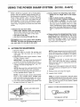
USING
THE POWER
SHARP
Model 354870 is equipped with a Power Sharp
System that will perform approximately
80% of
the sharpening necessary for the saw chain.. The
Power Sharp System uses a built-in grinding
stone to sharpen the cutter top plates and set
depth gauges. As the built-in sharpener is used,
the cutter side plates gradually will be alteredr
Hand filing is required to correct the cutter side
plates
e Sharpen the saw chain when:
--wood
chips become small and powdery.
Wood chips made by the chain should be
about the size of the teeth of the chain
--saw cuts to one side.
--saw has to be forced through the cut.
ICAUTION:I ALways wear gloves when handling
the chain. The chain can be sharp enough to cut
you, even when it is too dull to cut wood.
A.
AUTOMATIC
SYSTEM
(iVIODEL.354870)
® Always replace the sharpening stone when
--sparks are no longer seen at lull adjustment
--only 1/4 inch of stone is remaining
--stone has become cracked or damaged.
w a new chain is installed. The used stone
will be worn to the shape of the old chain
and can cause excessive wear to a new
chain. Replacement chain comes supplied
with Stone Cartridge Replacement #69099.
Refer to replacement instructions
on page
12..
® Always remove the sharpening stone if a conventional chain is substituted for the Power
Sharp Chain, See instructions
for removing
the Stone Cartridge on page 12. Use replacement chain #32-3638 Follow chain sharpening instructions
on page 16..
SHARPEHIN@
1, Stop the engine.
2. Place the saw on a solid, flat surface and
make sure that the chain wilt not contact
any object..
3. Adjust the chain with correct tension
Refer
to Chain Tension, page 7.
IMPORTANT: The chain must be tensioned
correctly for proper sharpening to occur.
4.. Start the engine and operate at half to three/
quarters throttle during steps "5", "6", "7",
and "8".
NOTE: Saw must be running at half to three/
quarters throttle before knob is pressedr
5 Push the Power Sharp Knob down slowly until fully pressed down. Figure 19
NOTE: if stone should contact chain before
knob is fully pressed down, release knob
and turn knob counterclockwise
until condition does not exist. Repeat Step "5" again..
6. Turn knob slowly clockwise until sparks can
be seen as shown in Figure 19
NOTE: Proper sharpening occurs when a light
flow of sparks is seen. Improper sharpening is
shown by a heavy fiowof sparks or no sparks.
7 Release knob and turn one additional
clockwise,
"click"
NOTE: It is important to turn the knob only
one "click" each time the knob is pressed,.
More turnswill result in making the chain dull
instead of sharp.
8 Press knob firmly against chain and hold for
10-15 seconds or until sparks can no longer
be seen
9. Release knob and stop the engine.
t0. Inspect chain cutters..
NOTE: A properly sharpened cutter will show
grinding marks across its entire width, Figure
20 If cutters do not appear sharp or burrs are
seen on the top front of the cutters, repeat
Steps "7" and "8".
INSPECT CUTTERS FOR GRINDING MARKS
SPARKS
ARE
SEEN
HERE
TOP VIEW OF CUTTER
POWER SHARP KNOB
Figure ! 9
Figure 20
11
B.
HAHD
FUL,H@
Sharpen the side plates by hand after every 3rd
to 5th time the Power Sharp System is used.
Items Required:
Gloves
5132" file
file holder
flat file
vise
the chain for proper tension,
page 7.
SIDE PLATE
Figure 21
HOLD FILE
HOLDER LEVEL
WITH THE 22 °
GUIDE MARK
PARALLEL TO
GUIDE BAR
Clamp the bar in a vise to hold the chain
steady. Do not clamp the chain.
3.,
Figure 22
NOTE: Work at the midpoint of the bar, moving the chain forward with a screwdriver
as
each cutter is filed°
,
Support the square rod on the fife holder(with
5132" round file) on cutter top plate,, Figure 21
5, Hold the file holder level with the 22 ° guide
mark parallel to guide bar. Figure 22
6 File from inside toward outside of cutter in
one direction only -- 2 or 3 strokes per side
plate edge should be enough, Figure 23
0 NV
Figure 23
SIDE
PLATE
8,,
Cu
Maintain
24.
a 1/32" side plate projection.
Figure
File all side plates on one side of the chain,
then move to the other side of bar and file remaining side plates.,
REPLACE
OR RBMOVE
,'STONE AND CARRUER
5 Reinstall
12
Carburetor
SIDE PLATE
T
22°ggV' gR___L
/
PLATE t
PROJ1132"
ECTIO N _'_
1
Figure
24
Figure
25
THE
ASSEMBLY
1. Remove Carburetor Cover and Bar Clamp,
2. Remove the two screws which hold cartridge
assembly to crankcase_ Figure 25,
3. Discard old assembly.
4, Install new cartridge assembly,
NOTE: Be careful
fall ouL
fl
_-- 1132"
\ -"_ I!....
NOTE: Avoid hitting the top edge of the cutters when filing the side plate,,
,
FILE
/
PLATE
Stop the engine,
2. Adjust
ROUND
GAUGE
NOTE: If abrasive materials such as rocks, nails,
sand or dirt are contacted by the chain, the side
plates should be checked more often. Damage
to the cutters caused by abrasive materials
usually results in discoloration
spots where the
chrome has been worn away. Cutter side plates
should be filed until these spots are removed.
,
SUPPORT
FLAT SIDE
OF FILE HOLDER
ON TOP OF CUTTER
STON E
CARTRIDGE
ASSEMBLY
not to let the Slide Button
Cover and Bar Clamp,
TYPES
OF CUTT N@
A.
CUTTONG
BAS!;C
1. IMPORTANT
T_CHNIQUE
POINTS.
2_
a. Cut wood only. [3o not cut metal, plastics,
masonry,
non-wood,
building
materials;
etc
b. Stop the saw if the chain strikes a foreign
object. Inspect
the unit and repair or
repace parts as necessary,
C,
Keep the chain out of dirt and sand. Even a
small amount of dirt will quickly dull a
chain and thus, increase the possibility of
kickback.
u,,
BEGIN
!SPUR
CLJTTING
AGAINST
WITH
THE
LOG.
Figure 26
3"RI_E
FELII
PROCEDURE
Practice cutting a few small logs using the
following technique to get the "feel" of using
your saw before you begin a major sawing
operation.
a. Accelerate the engine to full throttle just
before entering the cut by squeezing the
Throttle Trigger.
b. Begin cutting
with the spur against the
log. Figure 26
c. Keep the engine at full throttle the entire
time you are cutting.
d. Allow the chain to cut for you; exert only
light downward pressure, If you force the
cut, damage to the bar, chain, or engine
can result.
e. Release the Throttle as soon as the cut is
completed,
allowing the engine to idle If
you run the saw at full throttle without a
cutting toad, unnecessary wear will occur
to the chain, bar, and engine..
f. Stop the engine before setting the saw
down after cutting.
UNG TI_CHNUQUES
1. PLAN
YOUR
SAWING
OPERATION
CAREFULLY
IN ADVANCE
a. Clear the work area,, You need a clear area
all around the tree where you can have
secure footing
b_ Study the natural
conditions
that can
cause the tree to fall in a particular direction. The tree wilt be likely to fall:
1.) In the direction the WIND is blowing
2.) towards the direction
of the LEAN of
the tree
3,) on the side that is the HEAVIEST with
branches.
c° Make sure there is enough room for the
tree to fall.
d. Remove dirt, stones,
loose bark, nails,
staples, and wire from the tree where cuts
are to be made.
e. Plan a clear retreat path to the rear and
diagonal to the line of fall Figure 27
DON'T
PUT YOURSELF
WARNING!
DO NOT CUT
--near electrical wires or buildings.
--if you do not know the direction of tree fall.
--at night since you will not be able to see well.
--during
bad weather--strong
wind, snow, rain,
etc.
2. FELLING SMALL
DIAMETER
'!ii_';?Checkthe Wi_?
Don't cut down wind.
THAN
6"
a, if you know the direction of fail:
t.) Make a single felling cut on the side
away from the direction of fall,
2.) Cut all the way through,
3,) Stop the saw, put it down, and get away
quickly on your planned retreat path.
b. If you are not sure which way the tree will
fall, use the notch method described for
felling large trees,
IN THESE
r,,,,t"iiiiiiiii!ii!iiiiii
ili ii
-
TREES--LESS
/ Check the
• Don't cut on lean side.
POSITIONS
t
r,,
Check the bal'ance.
Don't cut on weighted side: .
13
3. FE/.LING
LARGE
OR MORE
TREES--6"
DIAMETER
The notch method is used to cut large trees A
notch is cut on the side of the tree in the
desired direction of fall, After a felling cut is
made on the opposite side of the tree, the tree
wilt tend to fall into the notch.
a Make the notch cut Figure 28,
1) Cut the bottom of the notch first,
through 113 of the diameter of the tree,.
2) Complete
the notch by making
the
slant cut,
3)
Remove the notch of wood,,
b., Make the felling cut on the opposite side of
the notch about 2" higher than the bottom
of the notch.
c Leave enough uncut wood between the felling cut and the notch to form a hinge
Figure 29
j
OF
FAL " .... f
DIRECTION
<=========
OF FALL
NOTE: The hinge helps to keep the tree
from twisting and falling in the wrong direction
d,
Use a wedge if there is any chance that the
tree will not fail in the desired direction
NOTE: Stop cutting before the felling cut is
complete; use a wedge to open up the cut.
e
Be alert for signs that the tree is ready to
fail:
1,) cracking sounds
2) widening of the felling cut
3) movement in the upper branches
As the tree starts to fall, Stop the saw; put
it down, and get away quickly on your planned retreat path.
\
FELLING CUT
NOTCH
DIRECTION
OF FALL
\
OPENING OF
FELLING CUT
2"
==-,,=,e_
CLOSING
OF NOTCH
HINGE HOLDS TREE ON STUMP AND
CONTROLS THE FALL.
Figure 27
C.
Figure 28
Figure 29
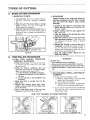
BUCKIN@
e Bucking is the term used for cutting a fallen
tree to the desired log size,
e Two types of cutting are used (Figure
30):
--Overcutting -- begin on the top side of the
log with the bottom of the saw against the
log; exert light pressure downward.
1. BUCKING
a Overcut
--
WITHOUT
with a 1t3 diameter
WARNING!
Never turn the saw upside down to undercut.
The saw cannot be controlled in this position.
OVERCUT
Figure 30
14
cut
b Roll log over and finish with an overcut
-- Undercutting -- begin on the under side of
the log with the top of the saw against the
log; exert light pressure upward. During
undercutting,
the saw will tend to push
back at you,_ Be prepared for this reaction
and hotd the saw firmly to maintain control
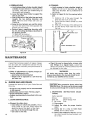
e Make the first bucking cut 1/3 of the way
through the log and finish with a 2/3 cut on
the opposite side. As the tog is being cut, it
will tend to bend, The saw can become pinch.
ed or hung in the log if you make the first cut
deeper than 1/3 of the diameter of the log
A SUPPORT
, ,,,,,,,_
u
,,, ,,r
WARNING!
tf saw becomes pinched or hung in a tog, don't
try to force it out. You could lose control of the
saw resulting in personal injury and/or damage
to the saw° Stop the saw and drive a wedge into
the cut until saw can be removed easily° Be
careful not to damage the chain with the wedge,
Figure 31.
2, BUCKING
--
A SUPPORT
USING
ANOTHER
LOG AS
(Figure 32):
Figure 31
WARNING!
ALWAYS STAND UPHILL FROM THE LOG.. The
cut portion will roll down hill,
B
a In area A:
1)
2)
Undercut 1/3 of the way through
log
Finish with an overcut
the
b In area B:
1)
2)
Overcut, 113 of the way through the log
Finish with an undercut
3. BUCKING
m USING
A STAND
(Figure
33):
a In area A:
1)
2)
LOG AS A SUPPORT
Figure 32
IAI
2ND CUT
Undercut 1/3 of the way through
log
Finish with an overcut
B
1ST CUT
the
b, tn area B:
I,) Over cut 1/3 of the way through
2) Finish with an undercut
IA
2ND CUT
the tog
CUT
CUT
FIRST
CUT
Figure 33
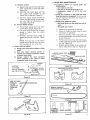
#,
DEBRANCHnNG
AND PRUHmNG
e Work slowly, keeping both hands on the saw
with a firm grip, Maintain secure footing and
balance,
• Watch out for springpoles. Use extreme caution when cutting small size limbs. Slender
material
may catch the saw chain and be
whipped toward you or pull off balance,
e Be alert for springbacko Watch out for branches that are bent or under pressure as you
are cutting
to avoid being struck by the
branch or the saw when the tension in the
wood fibers is released
e Keep a clear work area° Frequently
clear
branches out of the way to avoid tripping over
them
WARNING!
BE ALERT
FOR AND
GUARD
AGAINST
KICKBACK° DO not allow the moving chain to
contact any other branches or objects at the
nose of the guide bar when debranching or pruning. Allowing
such contact
could result in
serious personal injury.
WARNING!
Never climb into a tree to debranch or prune° Do
not stand on ladders, platforms, or in any posi.
tign which might cause you to lose control of
the saw°
F
USE COMMON SENSE
KEEP THE TREE BETWEEN
YOU AND THE SAW
15
1. DEBRANCHING
a, Limit debranching
2. PRUNING
to limbs shoulder height
debranch a tree after it is
then can debranching
be
properly_
lower limbs to support the
or below. Always
cut down, Only
done safely and
b. Leave the larger
tree as you work.
co Start at the base of the felled tree and work
towards
the top cutting branches
and
limbs, Remove small limbs with one cut
Figure 34
d. Keep the tree between you and the chain.
Cut from the side of the tree opposite the
branch you are cutting
e, Remove larger, supporting
branches with
the 1/3, 213 cutting technique described in
the bucking section.
1,) Start with an overcut
2,) Finish with an undercut
Remove
a, Limit pruning to limbs shoulder height or
below. Do not cut if branches are higher
than your shoulder. Get a professional
to
do the job
b. Refer to Figure 35 for the pruning technique,
1)
2)
3)
4)
Undercut 1/3 of the way through the
limb near the trunk of the tree
Finish with an overcut farther out from
the trunk,
Keep out of the way of the falling limb,
Cut the stump flush near the trunk of
the tree
_J
I!
t_
SECOND
Zi/
PRUNING
CUT
,v j
small limbs
with
one cut,
_ FIRST PRUNING CUT
Figure 34
Figure 35
NAINTNNAN@N
A good maintenance program of regular inspec.
tion and care will increase the service life and
help to maintain the safety and performance of
your saw,
• Make all adjustments or repairs (except carburetor adjustments) with:
--spark plug wire disconnected
--engine cool as opposed to a unit that has
just been run,
Am
WARNtNG_
All chain saw service other than the maintenance described in this manual should be performed by your SEARS Service Center.
@U DE BAR AND CHAllN
Increase the service
Chain by:
life of your Guide Bar and
--Using the saw properly and as recommended
in this manual
--Maintaining
correct Chain Tension, page 7.
--Proper lubrication, page 8,
--Regular maintenance as described in this section.
1. CHAIN
MAINTENANCE
e Sharpen the chain when:
_wood
chips are small and powdery. Wood
chips made by the saw chain should be
about the size of the teeth of the chain
--saw has to be forced through the cut,
--saw cuts to one side°
16
e Check the saw for loose bolts, screws, nuts,
and fittings on a regular basis. Loose fas.
tenors can cause an unsafe condition as well
as damage to your saw
[CAUTION:]Wear
protective gloves when handling the chain, The chain can be sharp enough
to cut you even though it it too dull to cut wood.
a, SHARPENING
.354830)
Items required:
Gloves
3116" file
6" file holder
INSTRUCTIONS
(Model
Medium file
Depth Gauge Tool
Vise
l r) Stop engine.
2.) Adjust the chain for proper tension,
page 7
3.) Clamp bar in a vise to hold chain
steady, Do not clamp chain
Work at the midpoint of the bar, moving
the chain forward by hand as each cutter is filed
2. GUIDE
5.) Sharpencutters.
a)
Support flat side of file holder (with
3116" round file) on cutter top plate,
Figure 36
Hold the file holder levef with the
30 ° guide mark parallel
to the
center Iine of the bar, Figure 37
b)
c)
File from inside toward outside of
cutter, straight across, in one direction only, Use 2 or 3 strokes per cutting edge., Figure 38
6.) Correct Depth Gauges°
a)
Place depth gauge tool over each
cutter depth gauger Figure 39
b) File level with the flat file if depth
gauge is higher than the depth
gauge tool
c) Maintain
rounded front corner of
depth gauge with a flat file. Figure
40
NOTE: The very top of the depth
gauge should be fiat with the front
half rounded off with a flat file
b. CHAIN
REPLACEMENT
BAR MAINTENANCE
e Conditions
which can require guide bar
maintenance:
--saw cuts to one side
--saw has to be forced through a cut
--inadequate
supply
of oil to bar and
chain.
e Check the condition of the guide bar each
time the chain is sharpened. A worn guide
bar will damage the chain and make cub
ring more difficult
e Replace the guide bar when:
--the inside groove of the guide bar rails is
worn.
.--the guide bar is bent°
a
b,
Remove the guide bar to service
Clean oil holes at least once for each
five hours of operation,
c
Remove sawdust
from the guide bar
groove periodically with a putty knife or
a wire, Figure 41
d Remove burrs by filing the side edges
of the guide bar grooves square with a
flat file, Figure 42
e,, Restore sguare edges to an uneven rail
top by filing with a flat file, Figure 42
1,,) Replace the chain when cutters or links
break.
2.) See your Sears Service Center
to
replace and sharpen individual cutters
to match your chain°
3.) Always
replace
the worn sprocket
when installing
a new chain to avoid
excessive wear to the chain.
SUPPORT
FLAT
"-7
SIDE
I _
OF FILE HOLDER
oNTOPOFCUTTER
ROUND
FILE
_'-'_x.
_
Figure 39
V
[:11]_
DEPTH
k__._GUAGE
MAINTAIN ROUNDED CORNER
OF DEPTH GAUGE
TEPPLATE
SIDE
PLATE
v
Figure 36
KEEP 30 ° MARK
PARALLEL
TO THE
CENTER OF
THE GUIDE
BAR
Figure 40
REMOVESAWD'US,
..........
J2
FROM GUIDE BAR GROOV_
V
Figure 37
,ll
Figure 41
CORRECT
GUIDE BAR
GROOVE
Figure 38
WORN GROOVES
Figure
42
FILE EDGES
SQUARE
17
B= BGHaTBON, COOLnN@ AND EXMAUST
e Carbon deposits will build up on exhaust
pods, spark arrestor, muffler, and spark plug
as the saw is used, All of these parts should
be cleaned at the same time to prevent
engine damage, overheating, loss of power,
and hard starting.
e Clean pads:
--as required
--at least once for each 25-30 hours of operation
1. COOLING
AND
EXHAUST
SYSTEM
e Carbon build-up on the cooling and exhaust system can cause the engine to
loose power in a cut.
SYSTEMS
Items required:
--wire brush
--3/8" wrench
--hardwood
stick
a_ Disconnect the spark plug
b. Remove
the muffler,
baffles,
and
screen. Figure 43,
c. Pull the starter rope until the piston
moves far enough to close the exhaust
ports.
d. Scrape the carbon deposits from the
exhaust ports and surrounding exhaust
chamber
using
a hardwood
stick.
Figure44o
e Keep the spark arrestor clean at all times.
e Replace the spark arrestor when breaks in
the screen are found.
SPARK ARRESTOR
ICAUTIONiJDo not use a metallic scrap.
ing tool as you might damage the
piston,
e.
HEAT SHIELD
f.
\
g.
\
Blow out toosened carbon with compressed air.
Clean the spark arrestor screen with a
wire brush or replace if breaks in the
screen are found.
Reassemble muffler parts
MUFFLER
2. SPARK
SCRAPE CARBON
DEPOSITS FROM
EXHAUST PORTS
AND CHAMBER
PLUG
e Maintenance is indicated when the engine
is hard ti) start.
e Keep the spark plug:
--clean
--properly gapped (°025")
items Required: Small brush,
tooth brush, or a pocket knife°
C jo8 SPARK
NOTE: Be careful
when removing,
cleaning,
gapping and replacing
the
spark plug If it is damaged, it will not
work properly and must be replaced_
PLUG
d
e,
fo
,,i, i
i
Figure 45
18
as a
a_ Remove the carburetor cover_
b, Pull the rubber connector
from the
spark plug and remove the spark plug
from the cylinder
c. Clean deposits from the electrodes of
the spark plug with a small brush or a
pocket knife,
Figure 44
CHAMPION
such
Set the gap between the electrodes to
.025 using a wir_ or flat gauge° Figure
45.
Replace the spark plug in the cylinder
and attach the rubber connector.
Replace carburetor cover and knob.
•
A starter rope that breaks next to the pulley
can be repaired.
Replace a starter rope that breaks more than
2 or 3 inches from the pulley.
e
NOTE: The recoil spring, located beneath the
pulley, is under tension_ If spring pops out, it
will require considerable
time and effort to
reinstall. For this reason, you may want to let
your Sears Service Center handte this repair
If you do try to repair the starter rope and the
recoil spring pops out, take the unit to your
Sears Service Center
Remove the four screws
fan housing. Figure 46.
on the side of the
NOTE: Notice the different
lengths
screws
and their proper locations
removing the screws
,
of the
while
Remove the fan housing..
34 If the starter rope is not broken, release the
spring tension by pulling about 12 inches of
rope from the pulley and catch the rope in
the notch as shown.. Figure 47.
4_
5. Remove the pulley screw in the center of the
pulley. Figure 48.
6. Lift the puiJey carefully whi_e gent_y twisting it
counterclockwise
_
, and remove the
old rope.
7. Move away from the fuei tank and burn the
end of the new rope to go into the pulley.
8. Pull the burnt end while hot through a rag to
smooth it.,
9. Feed the rope through the housing and the
round starter hole.. Figure 48,
10 Put the rope into the pulley groove and up
through the hole,.
11 Wrap rope counterclockwise
around puiley
rachet end and tuck loose end back under
rope leaving a 3t16 to 5/16 inch tail.
12. Rewind atl the rope onto the pulley,
counterclockwise
turning
13 Set the pulley into the housing; push it down
and engage the spring.
14, Replace and tighten the pulley screw,
15. Pull out 12 inches of rope and catch the rope
in the slot in the pulley. Figure 49.
16. Turn the pulley 3 complete
turns clockwise,
winding up the spring
NOTE: The tension on the starter spring will
be released if the rope has broken.
17o Hold the pulley and pull the starter rope to
the full extent of length and let the rope rewind slowly.
Turn the pulley counterclockwise
spring tension is released.
18 Replace fan housing with the four screws
their proper location,
untit the
_'
in
PULLEY
SCREW
t
/
Figure 46
Figure 48
TURN PULLEY
TO RELEASE
TENSION
_J
i , H,l,,,
Figure 47
,,H,,,,ll,,,,m,
N
Figure 49
19
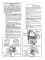
D,
CLUTCH,
DRUM
AND SFROCKET
WARNING!
Do not start engine without Guide Bar, Chain,
and Bar Clamp completely
assembled,
The
clutch can come off without the guide bar and
chain completely assembled and serious injury
could result° Do not loosen and spin the clutch
off of the crankshaft
with a power tool. The
clutch shoes and drum could separate causing
the clutch to violently fly apart and serious personal injury could result.
e Take the saw to your nearest Sears Service
Center for full clutch inspection and service
after each t00 hours of operation°/t is recommended that you do not try to service the
clutch yourself unless you are a competent
small engine mechanic and have the proper
clutch service tools, Proper disassembly
and
repair of the clutch is extremely important to
the life of the engine and the safety of the
operator.,
e Clutch maintenance
is required when:
_the chain continues to turn while engine
idles after the idle speed screw has been
adjusted to its capacity,
--slippage
occurs during a cut.
--a chattering noise occurs during cutting.
e Clean the clutch, drum, sprocket, and surrounding area daily during heavy use of the
saw. Check to see that the clutch drum turns
freely and smoothly
• Inspect the sprocket regularly for wear. A
worn sprocket will make the chain run erratically and wil! shorten the life of the bar
and chain. Figure 50.
e Replace the sprocket whenever a new chain
is installed in order to gain the full life expectancy of the chain. Use the following procedure:
,ll,
,,,,J,,,,,
,,,,,,,
Items Required:
1,
2.
3,
4,
Scrench
9116" Socket Wrench
3t4" Socket Wrench
Remove the carburetor
cover and pull the
spark plug away from the rubber connector.
Remove the bar clamp, outer guide plate,
guide bar, and chain. Figure 51_
Remove the fan housing.
Use a 9116" socket wrench on the flywheel
nut to keep the crankshaft
from moving
Figure 52,,
NOTE: Place the socket handle forward as
shown in Figure 52.
5 Remove the clutch with a 314" socket or end
wrench in a clockwise direction, Figure 53,
[CAUTION:IDo not remove the clutch with a
punch or a powertool as damageor breakage
to the clutch could occur.
6o Remove worn sprocket and replace.
7. Install clutch in a counterclockwise
direction,
Figure 53
8, Hoid flywheel by hand and torque clutch to
22 ft. pounds.
NOTE: Do not hold a wrench on the flywheel
nut when replacing the clutch., This could
loosen the flywheel nut,
9. Reinstall
fan housing,
bar chain and bar
clamp,
,11111,,i,
i ,
KEEP
CRANKSHAFT
FROM MOVING
,,,,Li
CHAIN WEAR ON DRIVE SPROCKET
WEAR IS VISIBLE
ON SPUR TYPE
(Model .354830)
RIM TYPE WEARS INSIDE
(Model .354870)
Figure 50
Figure 52
REMOVE CLUTCH
BAR CLAMP
OUTER
BAR MOUNTING
NUTS
20
|DE PLATE
CLOCKWISE
INSTALL CLUTCH
COUNTE RCLOCKWtSE
Figure 53
Ea
CARBURETOR
ADJUSlFIM N3'S
e The carburetor has been adjusted at the factory for sea level conditions, Adjustment may
become necessary
if the unit is used at
significantly
higher altitudes or if you notice
any of the following conditions:
--Chain moves with the engine at idle speed.
--Loss of cutting power which is not corrected by air filter or muffler screen clean.
ingo
--Engine
dies or hesitates when it should
accelerate.
e Permanent damage will occur to the engine if
incorrect carburetor adjustments are made./t
is best to let your Sears Service Center make
carburetor
adjustments
If you choose to
make the adjustment yourself, follow the procedure below very carefully.
WARNING!
The chain may be moving during this procedure.
Wear your protective gear and observe all of the
safety precautions.
.... i
1. PREPARATION
a. Stop engine
b. Use a fresh fuel mixture
with proper
gasoline/oil
ratio
c, Place the saw on a solid, flat surface and
make sure the chain will not contact any
object,.
d Locate the three (3) Carburetor adjusting
screws located on the fan housing side of
the saw. Figure 54
e. Turn the Low Speed Mixture Screw and the
High Speed Mixture Screw clockwise
just until they stop, Do not turn the screws
until they are tight as you may damage
the needle seats,
c, Run the engine for a few minutes to bring it
up to operating temperature.
NOTE: The engine must be at operating
temperature for proper adjustments
to be
made.
3o LOW SPEED MIXTURE ADJUSTMENT
a, Turn the Low Speed Mixture Screw slowly
clockwise
_
until the RPM starts to
drop° Note the position,.
b Turn the Low Speed Mixture Screw counterclockwise
_
until th RPM speeds
up and starts to drop again, Note the position.
c, Set the Low Speed Mixture Screw at the
mid-point between the two positions
4. IDLE SPEED ADJUSTMENT--II
a, Allow engine to idle.
b Adjust if the chain is turning by turning the
Idle Speed Screw counterclockwise
_
o
c° Squeeze the throttle
trigger;
The saw
should accelerate without hesitating,
NOTE: It may be necessary to recheck the
low speed mixture setting after the idle
speed has been reduced by repeating "Low
Speed Mixture Adjustment"
as in step 3
above,
5. HIGH SPEED MIXTURE ADJUSTMENT
a. Make a test cuL
b, Adjust if the saw smokes or seems to have
low power in the test cut by turning the
High Speed Mixture Screw 1t16th of a turn
clockwise
c. Repeat test cut,
d Repeat adjustment
smoothly..
f, Turn the Low Speed Mixture Screw and the
High Speed Mixture Screw one full turn
counterclockwise
2. IDLE SPEED ADJUSTMENT--I
a. Start the engine and allow to idle.
b, Adjust if the engine dies or stops by turning
the Idle Speed Screw I/2 turn clockwise
NOTE: To increase idle speed, turn the Idle
Speed Screw clockwise
_
To
decrease idle speed, turn the Idle Speed
Screw counterclockwise
until
the
saw
runs
[CAUTION: 1 Never set the High Speed Mixture
Screw less than 7/8 turn open, This is too lean
a setting and will ruin your engine.
.
IDLE SPEED ADJUSTMENT--Ill
Recheck for proper idle mixture setting,,
NOTE: It may be necessary to repeat Idle
Speed Adjustment-t
and Low Speed Mixture
Adjustment
7. CHECK
ACCELERATION
Adjust if there is a slight hesitation, by turning the Low Speed Mixture Screw 1/16 of a
turn at a time counterclockwise
_
until you have smooth acceleration,
NOTE: Check to be sure the chain is not turning when engine is idling. If chain moves at
idle speed, repeat Idle Speed Adjustment-ll
21
Fn
AmR F_LTER
e A dirty air filter.
_reduoes
cutting power
--increases fuel consumption
e Clean the Air Filter:.
--frequently, especially under very dusty
conditions.
--always
after 10 tanks of fuel mixture or 5
hours of operation whichever is less.
.,_AI
R FILTER
ICAUTION:jNever operate the unit without the air
filter in place as damage to the engine can ocour.
Items Required:
paint brush.
soft bristled
brush, such as a
1_ Clean off the carburetor cover and the area
around ito
2. Close choke to prevent dirt from entering the
carburetor.
& Remove the carburetor cover. Figure
4. Remove the air filter carefully_
5. Soak the filter in soap and water.
55.
[CAUTION:] Do not use gasoline or other flam.
mable liquid to clean the filter as this can
cause a fire hazard.
6. Brush away all dust and debris from the filter.
7. Allow filter to dry.
8. Brush away all debris from surfaces which
were covered by the carburetor cover.
9. Replace filter and carburetor cover.
Figure 55
Gs
CO_T_R=V_
TM
V_RATIO_
SYSTEM
This saw is equipped with a counter vibration
system consisting of 5 isolator mounts Figure
56 The Isolator Mounts protect the user from
engine, bar, and chain vibration similar to the
way shock absorbers on a car protect from jolts
and bumps in the road
1. Check isolators each time the saw is used.
2, Replace isolators when:
--vibration
increases
--mounts
develop
an out of round
or
swollen
shape usually
caused
from
exposure
to gasoline
and oil for long
periods of time
H.
OCCURS.
COUNTER
VtBE MOUN
Figure
56
STORA@E
When storing your saw for over 30 days always:
1
Drain fuel tank in a safe manner (see Important Points, page 8.)
2_ Start Engine and allow to run at an idle
speed until the engine stops..
NOTE: This will remove most of the fuel from
the fuel system
ICAUTION_ Wear protective gloves when handling the chain. The chain is sharp and can
cut you even when it is not moving.
11. MAIINTtENANCE
Available
Key No
1
but not furnished
2
3
Catalog No
32-36525
32-36521
32-36565
32-36557
3
4
5
6
7
8
Drain oil tank
Remove, clean, and dry the bar and chain
Store the chain in a container filled with oil
to prevent rust.
Apply a coating of oil to the entire surface of
the bar and wrap it in heavy paper, cloth or
plastic
Clean the outside surfaces of the engine
Store the saw in a dry, placeout ol the reach
of children and away fromwhere fuel vapors
can reach open flames
from hot water
heaters, furnaces, etc
ACCESSORES
with your saw
--t
22
3. Replace all five isolators when a failure to one
Description
File - 3/tS" die. - Twin peck
File - 5/16" die - Twin pack
FideGuide
Depth Gauge
Catalog No.
32_3640
32-36711
32-36512
32-36624
32-36555
32.36554
32-26911
32.3638
32-3639
32-36526
32-36618
Description
Spark Plug-Champion
CJ*8
Replacement
Recoil Cord
S;ide-on Chain Guard
Carrying
Case
2-Cycle Engine Oil
Bar and Chain Lubricant
Guide Bar - t8"
Chain (76LP-66}
-354830
(requires 7/32'" din, file)
Chain (76TS-66)
-354870
(includes S_one Cartridge
Ass'y)
File - 7/32"
din. - Twin pack
Chain Repair Kit
J.
TROUBLE
SHOOT_HG
CHART
TROUBLE
ENGINE
CAUSE
W1LL NOT START
ENGINE WILL NOT ]DLE
PROPERLY
ENGINE WILL NOT
ACCELERATE, LACKS
POWER OR DIES
IN THE CUT
1 ignition Swilch off
2 Fuel tank empty.
3 Spark Plug not firing
4 Fuel not reaching carburetor
1
2r
3
4
5
6
Engine flooded
Compression
low
5
6
!
Idling
t
2
Idle speed set too high
3
4
Low speed screw requires
Crankshaft
seals worn
5
Compression
speed set too low
RUNS HOT
adjustment
5
t
2
3
See Carburetor
Adjustments,
page 2!
Ctean or replace air lifter, page22
Clean or replace Spark Plug and recaP,
3
4
4
Clean exhaust system
arrestor, page !8
5 Contact Sears Service
Low Compression
I
2
3
4
Choke partially on
High speed needle requires
Air filter dirty
Oil rich fuel mixture
5, Crankcase
ENGINE
adjustment
Move switch to "Start"
FNI tank with correct rue! mixture, page 7
install new plug, page18
Check for dirty fuel filler; clean Check for
kinked or split fuel line; repair or replace
See Starling Instructions,
page 9
Contact Sears Service Center
Adjusf idle speed screw clockwise
to inincrease speed, page 2l
Adjust idle speed screw counterclockwise
to reduce speed, page 2!
See Carburetor
Adjustments,
page 21
Replace seals or contact Sears Service
Center
Contact Sears Service Center
2
low
1 Carburetor
requires
2. Air filter dirty
3 Spark Plug fouled
page 19.
4 Carbon build-up
5
ENGINE SMOKES
EXCESSIVELY
REMEDY
adjustment
leak,
1
2
3
4
5
t
2
3
Fuel Mixture Incorrect
Spark Plug incorrect
Carbon build-up
4
High Speed Mixture
including
spark
Center
Push Choke in
See Carburetor
Adjustments,
page 21
Clean or repiace air filler, page 22
Empty fue_ tank and refil! with correct
mixture, page 7
Contact Sears Service Center
luei
1. See Engine Fuel Mixture, page 7 .
2 Replace with correct plug, page 18
3 Clean exhaust systems including spark
arrestor, page 18
4 See Carburetor
Adjustments,
page 21
set too low
OIL INADEQUATE FOR
BAR AND CHAIN
LUBRICATION
1 Oil tank empty
20it
pump or oil filter clogged
3. Guide bar oil hole blocked.
1 Fill oil lank, page 8
2 Contact Sears Service Center
3. Remove bar and clean.
CHAIN MOVES AT
IDLE SPEED
1 Carburetor
requires adjustment
2, CtuLch requires repair.
1 See CarburetorAdjustments,
page 21
2. Contact Sears Service Center.
CHAIN DOES NOT MOVE
WHEN ENGINE IS
ACCELERATED
l
2
3
4
Chain tension too tighi
Carburetor
requires adjustment
Guide bar rails pinched
Ciutch slipping
1
2
3
4
CHAIN CLATTERS OR
CUTS ROUGHLY
1
2
3
4
Chain tension incorrect
Cutters dull, improperly
sharpened;
depth
gauges too high
Sprocket worn
Chain wear due to contact with dirt, sand
or frozen wood
Cutters damaged after striking foreign
material
1 See Chain Tension, page 7
2 See Chain Sharpening
Instructions,
page
page 16 (page ttt2
for Power Sharp)
3 Replace
4 Resharpen or replace Chain, page 16 -17
(page 11.12 for Power Sharp)
5 Contact Sears Service Center
Sharpen aH cutters evenly and uniformly
or replace chain See chain sharpening
instructions,
page 16-17 (page 11-12
for Power Sharp)
1
Chain cutter
2
3
Guide bar burred or bent; rails
Clutch slipping.
1 See Chain Sharpening
instructions,
paget6-t7{page
t1.12 for Power Sharp)
2 Repair or replace guide bar, page 17
3 Contact Sears Service Center
CHAIN STOPS WITHIN
THE CUT
CHAIN CUTS AT
AN ANGLE
1 Cutters
2
Chain
tops not filed flat
damaged
on one side
dull on one side
3. Guide bar bent, or worn.
uneven
See Chain Tension, page 7
See Carburetor
Adjustments,
page 21
Repair or replace, page t7
Contact Sears Service Center
1
Resharpen until all cutters have equal
angles and lengths, page 16 -17 (page 1t-12
lor Power Sharp)
2 Resharpee until all cutters have equal
angles and lengths, page 16-17(page
1H2
for Power Sharp)
3, Replace guide bar, page 17.
23
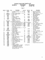
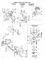
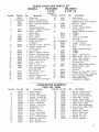
SEARS CHAIN SAW PARTS LiST
MODELS
358.354830
358.354870
3.7118"
3.7/18" PS
Figure
I
5O
44
23
36
1
5
45
29
\\\,
-\_
47 51 52
k___/
24
_ /,_
\59
62
SEARS
MODELS
CHAIN SAW PARTS LIST
358.354830
358.354870
3.7/18"
3.7/18" PS
Figure I
Key No.
1
Qty.
Description
Key No.
1 Flywheel Assembly _;3_- z;.59L,,_5"37
(incl # 2)
38
2 Spring - Starter Dog 5_o-zJ._9_7
2 Screw- Muffler Cover
39
2 Screw- Spur
40
1 Spur
1 Washer- Flywheel
41
1 Flywheel Nut
42
1 Screw- Starter Pulley
1 Washer- Starter Pulley
43
Retainer
44
1 Screw Disc Mounting
45
2
3
4
5
6
7
8
9
23_1-7
STD522525
15434
24476
1626
1722
15468
15123
10
11
12
13
!4
15
16
STD600603
30054
42066
24329
42051
42054
15364
17
18
19
20
11866
24392
24391
STD522505
1
1
1
2
2i
22
23
24
25
26
27
28
29
30
31
32
33
34
35
36
24385
24384
19097
STD600603
24232
28487
24388
24387
32051
15354
1684
42056
42052
24799
19098
10479
10461
1
2
2
AR*
1
1
1
1
1
2
1
1
1
1
2
2
2
1
t
1
1
1
Sealant Crankcase 3 oz_
%_ ¢,_(_
Disc - Recoil Spring Outer _'-"
a_
Bushing - Recoil Sprmg_ _ ,c,#L!_ - 1
Spring - Starter RecoilS"_o rC_&CS_,&_
Disc " Recoil Spring Inner:;_ _'q,;__
Screw- Fan Housing 5-_ ¢ j5;5_
(Top Front)
Fan Housing Assembfy.? .5o -L*iulq O.3
Shield Muffler
51
Muffler Cover
Screw - Muffler
52
BodyfCylinder
53
Screen - Spark Arrestor
DiffuserMuffler
54
Seat- Crankshaft
Screw - Air - Baffle
Baffle- Air
Pulley - Starter 5_'
c _ _ _ __,o
Back Plate- Muffler
Muffler Body
Bearings - Crankshaft
Thrust Washers - Crankshaft
Stud - Bar Mounting
Handle- Starter Rope
Rope- Starter
Cylinder
Gasket - Cylinder
Crankcase Assembly (.354870
& _354830) Right & Left Half
(incl, # 23, 29, & 31 on Fig. 1;
aIso includes from Fig 3, 22,
30, 43 & one of 37.)
55
56
57
58
59
60
61
62
63
Part No.
25556
15365
30073
15195
24756
24492
1624
39096
10355
STD580008
15366
39097
39071
39102
10444
19119
24334
39093
15425
23661
STD600603
STD511007
23732
39099
23575
24858
31107
64754
Qty.
Description
1 Decal Fan Housing
!
Screw- Fan Housing
(Lower Front)
1 Spark Plug (CJ-8Y) _iyl .:._._
1 Clip- High Tension
Lead Cylinder
2 Piston Ring
1 Crankshaft and
Rod Assembly
4 Screw- Cylinder
1 High Tension Lead
1 Piston Assembly
(incL #41)
1 Key- Flywheel
2 Screw - Fan Housing (Rear)
!
Boot- Spark Plug
1 ConnectorSpark Plug
1 High Tension
Lead Assembly
(Incl.# 44, 48, & 49)
1 Oil Cap Assembly
(Incl 52)
1 "O" Ring- Oil Cap
1 Clamp - High Tension Lead
(Crankcase)
1 Ignition Module (incf #
60 & 50)
2 Screw - Module Mounting
2 Clamp- Lead
2 Screw- Lead Clamp
9 Screw - Crankcase
1 Switch- Toggle
1 Switch Lead
1 Ignition Switch Nut
1 Plate- StartlStop
1 Scrench
I
Owner's Manual (not shown)
* As Required
25
SEARS
CHAIN
M O D ELS
SAW PARTS
358.354830
3.7/18"
Figure
LIST
358.354870
3.7/18" PS
2
MODEL
358.354870
3.7/18" PS
39
4O
46
33__
34
CARBURETORASSEMBLY
PART NO, 35094
1
1
14
15
-24
26
SEARS
M O D ELS
Key No.
1
2
3
4
5
Pa_ No.
24338
STD511003
10347
19107
24229
Qty,
1
l
1
t
I
6
7
19101
15387
1
2
8
9
10
11
11865
24383
35094
19099
1
1
1
1
12
13
15462
24373
2
2
14
15
16
17
18
t9
20
21
22
23
24376
25258
24349
15414
24-8-2815252
23364
23363
19093
10286
2
1
1
2
1
1
1
1
1
1
24
11827
24357
32053
25469
15245
1
1
1
1
2
25
26
27
28
CHAIN SAW PARTS LIST
358.354830
358.354870
3.7/18"
3.7/18" PS
Figure 2
Key No_
Description
Choke Rod
Screw. Choke Bracket
Brackel & Bushing Ass'y
Seal. Carburetor Adaptor
Adaptor CarburetorlCylinder
Gasket _ AdaptorlCylinder
Screw
Brace to
Rear Handle
Brace - Handle
Wire- Choke
Carburetor Assembly
Gasket Carburetor
to Adaptor
Shoulder - Screw _ Isolator
Isolator., Powerhead
to Rear Handle
Cup- Isolator
Spacer - Isolator (Center)
Bracket _ Carburetor Seat
Screw - Adaptor/Cylinder
Fuel Line 5_0-_&_
2/(,=
Washer Fuel Pick-Up
Filter- Fuet PickUp
Weight .. Fuel
Seal- Fuel Tank Neck
Fuel Tank Assembly
(Incl. #30 & 35)
Rear Handle - Right
Throttle Lock
Bushing Throttle Lock
Spring - Trigger
Screw _ Carburetor/Adaptor
Part No.
Qty,,
29
3O
19104
285O5
1
1
31
32
33
32059
24699
15168
1
1
3
25515
25516
10331
1
1
1
STD302213
25468
15403
24482
1
1
1
1
34
35
36
37
38
39
40
41
42
43
44
24976
25486.
24378
--14,8.26---"
15369
15393
1
1
1
1
2
t
45
46
15397
24877
1
1
47
48
49
5O
51
24548
1
1
25555
25425
25586
1
1
1
Description
Seal Adaptor
Fuel Line and Filter
Assembly (lncl,#18, t9, 20 & 21
Bushing - Trigger
Throttle Link
. Screw - Cylinder Shield
to Crankcase
Decal - Starting Instructions
_354830
.354870
Fuel Cap Assembly
(IncI #36)
"O" Ring Fuer Cap
Trigger- Throttle
Screw - Throttle Trigger
Knob'
Cover- Carburetor Ass'y.
°354830
,354870
Spring - Throttle Lock
Rear Handle _ Left 3.30 .. Q_
Screw- Rear Handle
Screw - Rear Handle
(Throttle Lock)
Screw - Rear Handle (Lower)
Retaining Ring - Carb.
Cover Knob
Air Filter
Gasket - Air Fi lter-5_'_,9- O / 9/.:
Cylinder Shields_O.#2_5"8_5 _
Knob - Adjusting (354870)
Decal Sharpening
instructions
- (,.354870)
CARBURETOR
ASSEMBLY
PART NO. 35094
Key Noo
1
2
3
4
5
6
7
8
9
10
11
12
13
14
15
16
17
Part No.
Qty.
35102
35015
35123
35119
35101
35115
35099
35109
35113
35069
35111
35106
35118
35097
35125
35105
35107
1
3
1
1
1
1
1
1
1
1
1
1
1
1
1
1
1
Description
Valve.Throttle
Screw - Valve
Fitting - Inlet (Elbow)
Spring ,rThrottle Rot
Shaft Ass'y-Throttle
Screw - Pump Cover
Cover- Fuel Pump
Gasket - Fuel Pump
Diaphragm - Fuel
Screen -Inlet
Gasket - Circuit
Valve-Inlet
Needle
Spring, Mtrg Lever
Lever - Throttle (Outer)
Bushing - Throttle Lv
Stop- Throttle
Ball. Choke Friction
Key No.
Part No,
Qty.
18
19
20
21
22
23
24
25
26
27
28
29
30
31
32
35022
35124
35096
35126
35116
35108
351 t4
35098
35021
35104
35103
35121
35117
35122
35023
1
1
1
1
2
1
1
1
4
1
t
1
1
2
2
Description
Spring - Choke Friction
Screen- Check Valve
Ring - Screen Retaining
Plate Ass'y- Circuit
Screw - Circuit Plate
Gasket - Mtrg Diaphragm
Diaph.. Ass'y _ Mtrg
Cover- Mtrg./Diaphragm
Screw Ass'y- Mtrg Cover
Valve- Choke
Shaft Ass'y- Choke
Spring- Idle Screw
Screw- Idle- Adj.
Needle- Hi & Lo
Spring - Needle's
27
SEARS
MODELS
CHAIN
SAW PARTS LIST
358.354830
3.7118"
Figure
358.354870
3.7118" PS
3
34\
_55
43
44
49
5O
.56
58
47
\66
59
48--
7O
@
MODEL
358.354870
3.7118" PS
68j
69
10
28
See Fig, 1 #36
_:/71
72
60
SEARS
/IODELS
CHAIN SAW PARTS
358.354830
3.7/18"
Figure
Key No.
1
2
3
5
6
7
8
9
10
Part No.
Qty,
STD511003
1
24351
24348
15357
32049
48069
24465
24353
1
I
1
I
I
1
1
10291
10466
24352
1
1
3
13
14
15
16
11625
25428
23373
24347
24225
15406
1
1
1
1
t
I
17
18
19
20
2t
22
23
23356
STD583037
23357
2;467
15509
STD560907
19103
t
1
1
1
3
1
1
24
25
26
27
28
2615
19029
15418
23358
10352
1
1
1
1
I
11
12
29
30
3l
32
33
34
24677
21038
10353
23699
22197
10289
1
1
1
1
1
1
35
36
37
38
39
24676
21031
2464
24691
24345
1
1
2
I
1
Description
Screw-Bracket
to
Crankcase
Bracket-Lever
to Crankcase
Lever- Manua_ Oiler
Thrust Washer
Bearing - Clutch
Drum & Sprocket Assembly
Plate - Clutch
Spring. Clutch
Clutch Ass'y.
(IncL #9, 11 &12)
.354830
354870
Shoe Clutch
Spider _ Clutch
.354830
.354870
Boot - Oiler Rod
Rod - Manual Oiler
isolator * Crankcase Side
Screw*Side lsolatod
Crankcase
Cap - Oil Pump
Retainer Ring - Oil Pump
Plunger- Oil Pump
Cap - Handguard
Screw/Handguard
Cotter Pin * Vent
Gasket Body
to Crankcase
Tubing Nut - Oiler
Quad Ring - Oil Pump
Washer - Oiler
Spring - Oil Pump
Oil Pump Assembly.
AutofManual
(Incl. #17, 18,
19, 24, 25, 26, 27, 30, 31, 32,
33, 34, 38, 39, 40, 41, 42 &
one of 37)
Spring - Oil Line Protector
Discharge Oil Line
Pump Body Assembly
Spring - Diaphragm
Button and Pintle Assembly
Oil Line Pick-Up Assembly
(lncL #29, 35 and 36)
Weight - Oil Pick.Up Line
Oil Line
Sleeve - 1/8 Tubing
Filter - Oil Pump Vent
Diaphragm - Oil Pump
LIST
358.354870
3.7/18" PS
3
Key No.
40
41
42
43
44
46
47
48
49
50
51
52
53
54
55
Part No.
19102
24321
15297
15422
2602
STD510810
24399
10462
10463
2603
STD600603
25556
24466
25631
22258
STD522510
56
57
58
51166
51241
44209
15362
59
60
24373
24376
61
62
63
64
65
66
67
25044
15445
15361
STD581018
25414
15385
15391
68
48071
69
70
15484
4746
7t
72
25421
69099
73
74
STD511005
052077
O25612
Qtyo
Description
1
1
1
1
1
3
t
Gasket- Cover to Body
Cover- Pump
Screw-Oil Pump Cover
Tubing Nut- Crankcase
Guide Bar Plate- Inner
Screw- Pump to Crankcase
Cover Plate _ Oiler
Bar Clamp Assembly
(tnC/o #61, 64, 65 & 66)
1 354830
1 .354870
1 Guide Bar Plate - Outer
4 Screw Oiler Cover Plate
1 Decal- Bar Clamp
1 Handguard
1 Decal Handguard
!
Handle Bar Assembly
2 Screw - Handlebar/
Rear Handle
Chain
1 35483O
1 .354870- Incl° #72
1 Bar. 18" SN
2 isolator Mount Spacer
Front Handlebar
2 Isolator- Front Handlebar
4 Isolator Cups- Front
Handlebar
1 Pin- Bar Adj.
2 Flange Nut- Bar Mounting
1 Spacer- Isolator
1 E Ring • Adj Screw
1 U-Clip - Bar Clamp
1 Screw- Bar Adjo
1 Screw- Isolator Mount to
Handlebar
1 Clutch Drum & Adaptor
Ass'y. * (7 Spline 3t8P) (.354870)
1 Plate Clutch (.354870)
!
Floating Rim- Sprocket
(3/8P - 7 Tooth)-(.354870)
1 Slide Button
1 Stone & Carrier Ass'y,
(lncl #71) - (,354870)
2 Screw- (,354870)
AR* Chain Repair Kit ( 354830 on
t
Label- Warranty (Guide Bar)
not shown
* As Required
29
NOTES
QUICK REFERENCE
PAGE
Read and follow all Safety Rules, Precautions and Operating Instructions.
Failure to do so can result in serious personal injury.
page
3-4
3
SAFETY RULES AND PRECAUTIONS
............................................
PREPARATION
.................................................................................
1,
2_
3.
4.
5
Wear personal protective gear -- gloves; safety footwear; snug fitting clothing;
head protection.
Check for worn, loose, or damaged parts and repair or replace as necessary
Check the chain for sharpness and tension.
Keep children, bystanders and pets out of the work area
Plan your sawing operation carefully in advance
and eye, hearing,
FUEL AND OIL ................................................................
1.
2
3.
4
5
6.
7.
THE ENGINE
,
6,
7,
8.
9
THE UNIT .........................................................
11
Cut wood only
Accelerate the engine to full throttle before entering the cuL
Begin cutting with the saw frame up against the log,
Cut only at full throttle..
Release the trigger as soon as the cut is completed
Stop the engine before setting the saw down after cutting.
MAINTENANCE
1
2
3
4.
.........................................................
Hold saw firmly with the saw chain free to turn without making contact with any object
Push saw away from you with your right hand while pulling the starter rope with your left hand.
Use no more than 15-18 inches of rope per pull
Putt _pe no more than 5-6 times
Release the trigger after engine starts allowing engine to idle.
OI:ERATING
1,
2
3
4.
5,
6
7
Eliminate all sources of sparks or flame where fuel is mixed, poured, or stored°
Use 1 part air-cooled, 2-cycle engine oil to 16 parts regular gasoline
Use gasoline not over 2 months old.
Mix and store fuel in an approved, marked container.
Mix and pour fuel in a weN-ventilated
area
Move a minimum of 10 feet away from fuel and fueling site before starting engine,
Fill the oil tank each time the fuel tank is refueled
STARTING
1.
2.,
3
4
5
and
.......................................................................
16
Disconnect spark plug before performing
maintenance except for carburetor adjustment
Adjust or have the carburetor adjusted if the chain moves when the engine idles
Check the guide bar for wear each time the chain is sharpened.
Clean the air filter frequently and always after 10 tanks of fuel mixture or 5 hours of operation, whichever
is less..
Clean ignition, cooling and exhaust systems at least once for each 25-30 hours of operation.
Take the saw to your SEARS Service Center for full clutch inspection after each 100 hours of operation.
Drain fuel tank in a safe manner after each use
Store saw in a dry place out of the reach of children,
NI'L
WATCH OUT FOR
KICKBACK
THE SAW WHEN
IT NEEDS REPAIR
NEVER USE THE SAW
WHEN TIRED
useAFiRM
QRIP
WITH BOTH HANDS
31
The Model
Number
will be found under the handle with the Serial
Number Always mention the Model Number when requesting
vice or repair parts for your Chain Saw
[Searsj
All parts listed herein may be ordered from any Sears
and most Sears Stores.
WHEN
ORDERING
REPAIR
PARTS,
FOLLOWING
INFORMATION AS SHOWN
Service Center
ALWAYS
GIVE
1N THIS LIST_
THE
1.
The PART NUMBER
3
The PART DESCRIPTION
2
The MODEL NUMBER
4
The NAME OF ITEM -Chain Saw
358.354830-3.7/18"
358.354870-3,7118"
MODEL NO.
358.354830.3.7/18"
358.354870.3.7/18" PS
ser-
PS
If the parts you need are not stocked
electronically
transmitted
to a Sears
center for expedited handling
localfy, your order will be
Repair Parts Distribution
When you buy
from Sears you
something
that
can offer ,_, Sears
Across
town
or
merchandise
get an extra
nobody
else
Service,
across
the
country, Sears Service follows
you,
providing
trustworthy,
competent service technicians
using
only
Sears specified
factory parts,
How
Repair
to Order
Parts
SEARS SERVICE
_, ..... s, l&oebuck
Sea1
64754-3-08383-1-08383
and
"
C()., Cbacag,),
IlL 6 ()68
4 U.S.A.
PRINTED
IN U,S A,
1