1
S_
_kL_
i
]
_!iii_
__i!_i_iiii_
i!i_:_ii_
_:_!_
_:_'::_s:_'_i
SECTgOHAL
DOORS
ONE PIECEDOORS
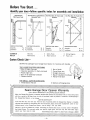
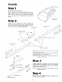
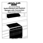
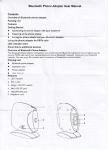
Before You Start.,.
identify your door •follow specific index for assemblyand installation
Sectional D DOt
With Curved Track
One Piece Door. Jamb Hardware_
Horizontal Track°
One Piece Door, No Track. Jamb
Hardware,,
One Piece Door. No Track, Pivot
Hardware,
.f
UX
gx
,,/_,
/
,,
/il
//
//
DOOR
\
DOOR
\
\
\
TRACK
/
//
TRACK
!
//
//
DOOR
9
iNSTRUCTiON
Assembly
INDEX
.........
installation
......
COMMON
INDEX
:
JAMB
HARDWARE
iNSTRUCTION
INDEX
INSTRUCTION
Pg_ 6
Assembly
.........
pg.
Pg,
installation
.......
Pg., 14
8
6
Warranty
............
Maintenance
.........
Assembly
2
3
iNDEX
INSTRUCTION
...........
Installation
PIVOT
pg,
..........
Safety Rules
Radio Controls
6
Assembly
Pg. 14
...........
........
Installation
3
17
INDEX
..............
P_
............
Wiring Diagram
.......
Parts Lists .............
CartonCheck List-SEARS Has packaged your Garage Door Opener in 2 cartons with handles,,_
THE LARGE CARTON
CONTAINS:
"_J_!Ji_i!#_
1 Box of Radio Controls
I
Box of chain
1
1
1
1
1
1
1
1
Curved door arm
_,_ '
Straight door arm
Bag of installation hardware
Handy hints labeF
Operator assembly (in foam end caps)
Plastic light lens
Box of rail assembly hardware
Owners manual
THE SMALL CARTON CONTAINS:
I Three-section Tee rai!
2 Sections of hanging strap
Sears Garage Door Opener Warranty
FULL
When
the Garage Door
a period
of
90 DAY
Opener
will,
for
90 days
the
Garage Door Opener,
WARRANTY
is installed,
from
at no
the
adjusted
day of
the
91st
day
until
one
year
adjusted
and operated
in accordance
defective
parts
Garage Door
Warranty
service
the United
which
in the
vary
is available
from
This
warranty
from
state
to
state.
OPENER
in accordance
repair
any defect
with
our instructions,
in material
Sears
or workmanship
in
with
gives
WARRANTY
the day
of purchase,
our instructions,
Opener,
by simply
States.,
and operated
purchase,
DOOR
charge,.
LIMITED
From
ON GARAGE
free of
contacting
you
specific
the
Sears will
charge.
the
when
You
nearest
furnish
pay
Door
Opener
replacement
is instatled,
parts
fm
any
labor,
Sears store
tegal rights,
Sears Roebuck
Garage
and you
or service
may
center
also
& Co., BSC 41-3, Sears Tower,
throughout
have other
Chicago,
6
Pg 14
rights
_L60684
20
21
Preparation
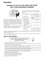
MAiNTAiN THE VALUEOF YOURGARAGEDOOROPENER
MAINTENANCEAGREEMENT
Here
\
is a comparative
Maintenance
chart
Agreement
indicating
coverage
the warranty
for
and
a Sears Maintenance
Agreement
....
.................. Coverage
AGREEMENT
,'
l
1
\
1) Defective
2) Service
Sears Garage
tested
for
Opener
Door
Openers
years of dependable
however,
may require
Sears warranty
plus
vides
from
coverage
use and
from
are designed,
The only
operation
service
unexpected
Agreement
bills
from
the maximum
to the
Agreement
acts of abuse, fire,
and parts
necessary
for proper
operation
not covered
coverage
are repairs
flood,
wind,
provided
by the Sears'
necessary
lightning
because
4) Preventive
of
check
and freezing.
YOUR SEARS SALESPERSON
AGREEMENT TODAY!
To obtain
the
best service
"Save-A-Call"
MA
MA
MA
MA
MA
MAiMA
by the
maintenance
at customer's
request
W = Warranty
CONTACT
TENANCE
MA
warranty
exceptions
Maintenance
MA
(technical
pro m
purchase,,
MA
MA
and non-technical)
use possible
MA
90 Days
Warranty
parts
The
normal
MA
W
to replace
3) Service,
4
MA
Parts
defective
Door
time to time,
repair
of obtaining
and
Any Garage
from
the Sears Maintenance
assures you
your
manufactured
Years of Ownership
2
3
from
your
OR LOCAL
Garage
Door
MA = Maintenance Agreement
SEARS SERVICE CENTER
Opener
and to avoid
MA
AND PURCHASE
needless inconvenience
ASEARS
or service expense,
MAIN-
please use
on Page 23 of this manual
RulesFor Safe Operation
WARNING-DOOR
SPRINGS CAN CAUSE FATAL INJURIES°
DO NOT ATTEMPT ADJUSTMENTS UNLESS YOU ARE
PROFESSIONALLY
TRAINED.
t,
Installation
2, Keep door
continuing
4, Your
with
must conform
hinges
rollers well
quiet
3,, The only
solvent
and wiring
part
door
new
inoperative°
6, Remove
7,, Before
must
opener
Fasten
opener
rag, then
that
balance
provide
all ropes connected
making
Handy
repairs,
Hints
lubrication
with
for proper
is the rail on which
operation
wilf insure
wood
to opener!
unless garage door is in sight.
(Sectional
screw or other
to the garage door.
the trolley
safety
door
for your
a stout
power
of the opener
have a serviceman
locking
label near walt button,,
months
in hardware
are weal{,
adequate
electric
codes.,
used every three
rail grease included
open with
disconnect
transmitter
A lubrication
If the door springs
Pin the door latch
and electrical
minimum
maintenance
and
the tracks,
requires
re-lubricate
impetus°
will
lubricated,
Do not lubricate
be in good
manual
8,, Do not operate
g,
of your
and a clean
normal
5o Your
and
operation.
to local building
rides., Clean the rail once a year with
package.,
system.
replace
track-type
disabling
It should
travel
up and down
freely
them_
device°
door),
Existing
locks
should
be made
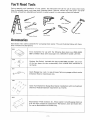
You'll Need Toels
During assembly and installation
of your opener, the instructions will call for use of various hand tools_
Have a stepladder handy, and those tools illustrated below: Hammer, electric drill (also 3/16" and 5/16"
drill bits), screwdriver', adjustable end wrench or socket wrench kit, wire cutters, pliers and hacksaw..
Adjustable
End
Wrench
Pliers
Stepladder
Wire
Socket
Cutters
Wrench
Accessories
Sears stocks many useful accessories for your garage door' opener. They are illustrated below with Sears
stock numbers and descriptions:
6545
Extra transmitter
for use with the following
Sears stock nos, 6550, 65.30,
6551 and 6531., Black with wood grain trim° ORDER BY CODE LETTER°
6528
j_,....
f4,_
J (_-.3)
.....
..
Outdoor Key Switch., Included with best models 6550 and 6551.. Just a turn
of the key opens the door automatically
from outside when transmitter' is
not handy..
6571
Quick-Release Key Lock. In case of power failure on garages without
entrances° Wood or metal doors only.
service
6785
Quick Turn Brackets for Garage Door Opener installations with low headroom
clearance, Reduces headroom requirement to 2 inches.
6538
Sectionalized T-Rail extension kit. ALlows opener to handle garage doors up
to 8 feet high,. Consists of replacement T-Rail section, chain and master link.,
For use on sectionalized rail models only.
.......
J
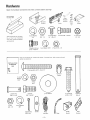
Hardware
Open the hardware containers
and check contents
before startingF
Rail Assembly
Hardware
Box
Chain
Retainer
Bracket
Trolley
Master
Rait
Link
Grease
12)
@
Items in this box
bly
of
the
nuts, bolts,
are actual
2 Lock
are for assem-
T.rail
IHustrated
screws
and washers
Washers
4 Carriage
1!4'°-20x
2 Nuts
3f8"
3/8--16
Bolts
1/2'"
2 Screws
3/8"'-16x7/8"
4 Lock Nuts
1/4--20
size
2 Washered
Screws
t Lock
Washer
5!16-
2 Nuts
5/t6--18
bolts,
screws,
5116"'-18x9tt6""
Items in this bag are for
washers are actual size
instalhng
the opener
Illustrated
nuts.
pins and
INSTALLATION
HARDWARE
) _I_IiIi_w!_I_1_iiii]]]_
BAG
Insulated
Staples
2 Lock
Washers
5/16"
2 Nuts
51t6"
O
l
2 Clevis Pins
318"xl
-1/t6"
4 Screws
3/8"-t6x7/8"
2 Ftat Washers
..5__
4 Nuts
3/8--
t6
4 Lag Screws
5/t6"xl-7!8"
Clevis
318'x3"
"-
4 Lack Washers
3!8"'
3 Cotter Pins
3132"x3/4-
Handle
'_'
Lead Wire
-5-
Rope
Header
Door
Bracket
Bracket
Pin
Assembly
Reverse
Step
Switch
Cover
1
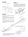
Open Rail Assembly Hardware Box
REMOVE SPROCKET COVER FROM OPERATOR: Place operator on packing material to prevent scratching chassis cover.
Remove sprocket cover from top of chassis by unfastening
screw as illustrated. DO NOT REMOVE REVERSE SWITCH
COVER,
Screw
Sprocket
ASSEMBLE
numbers
RAIL:
as illustrated.
seated
in square holes
surface
during
Assemble
Square
the
in sections
assembly,. THIS
3 Tee rail
necks
sections
on carriage
bolts
by the
must be
t and 3. Place Tee rail on flat
TEE RAIL SECTION
N£1
IS IMPORTANT!
TEE RAIL SECTION
N_-2
1/4
LOCK
Cover
NUT
(KEPS)
SQUARE
CARRIAGE BOLT
HOLES
TEE RAIL SECTION
N£3
I/4 X I/2 CARRIAGE
BOLT
Bolt section 1 to section 2, Use 1/4 inch by 1/2 inch carriage
bolts, and !/4 inch loci( nuts.
Join bolted sections 1 and 2 to section 3, Use 1/4 inch by 1/2
inch carriage bolts, and 1/4 inch lock nuts,
CAUTION:
DO NOT tighten lock nuts until
seated in square holes,,
Step
7/8
inch
screws,
3/8
inch
lock
Connect
the sprocket
Tee rail Use 3/8 inch by
washers
and nuts as itlust[ated,
nuts and screws securely..
CAUTION:
R_:LEASE
LEVER
:
necks are
3
ATTACH
SPROCKET
BRACKET:
bracket
assembly to the assembFed
Tighten
bolt
Make
certain
sprocket
with
Tee rait,
straight
bracket
assembly
is aligned
_SSEMBL_D
TROLLEY
Step
4
INSTALL TROLLEY ASSEMBLY:
onto the Tee rait as illustrated,
-6-
Slide the assembled trolley
Assembty
5
'i6x_t6 LG
BOLT
ATTACH
ASSEMBLED
operator
two
on packing
holes
chassis
in
motor
an illustrated,
TEE
material
RAIL
to
end of
avoid
Tee rail
For convenience,
TO
OPERATOR:
scratching
with
holes
place
in operator
a support
sprocket bracket
Fasten Tee rail to operator
with
screws 5/16 inch by 9/16 inch Tighten securely,
ASSEMBLED TEE RAIL
WITH
TROLLEY
Place
cover,, Align
two
under
washered
5/I6
NUT
SCREWDRIV
SPROCKET
BRACKET
OPERATOR
CHASSIS
\TROLLEY
BRACKET
TROLLEY STUD
FLAT END
MASTER
LINK
INSTALL
CHAIN:
Tee rai!
Slide
Thread
located
trolley
Insert
about
back
or nail
in the hole
of the sprocket
in
bracket,,
SMALL
SPROCKET
to this point
one of the 5/16
one end of
a screwdriver
6 inches
the chain
inch
master link from
hardware
box,
the
CAUTION:
the chain
Keep
nuts onto
the trolley
stud
to the fiat end of the t_'olley
coin
envelope
taut
included
white
Fasten
stud using
a
LARGE
SPROCKET
in the assembly
unwinding
it to prevent
kinking
Extend
back
to the
the
around
chain
the
trolley
around
small
Make
the idler
sprocket
certain
sprocket
bracket,
on the operator,
that
teeth
from
then
each
Proceed
forward
sprocket
engage the chain
CAUTION:
Tile
chain
illustrated
MASTER
LINK
RETAINER BRACKET
DC_WASHER _6
DLER
SPROCKET
CHiN
STUb
TROLLEY
J
Connect the chain to the chain retainer bracket using the second
master tink in the coin envelope Slide the chain retainer bracket
onto the chain stud as illustrated
Secure it to the stud with
the second 5/16 inch nut and lock washer,,
retainer
position
bracket
during
should
assembiy_
be kept
in the
Installation
Step 7
TIGHTEN
two 5/16
THE
CHAIN:
Tighten
the chain
by
inch nuts on chain stud de_ignated"inner"
adjusting
the
and "outer"
as illustrated,,
Chain is propmty
tightened
when it is approximately
1/2 inch above the base of the Tee rait at its midpoint
between
idler
CAUTION:
sprocket
Chain
and the operator
/
Keep the chain from twisting
as nuts are turned
Remove screwdriver
or nait from Tee rail
Base of Tee Rail
REPLACE SPROCKET COVER REMOVED
IN STEP 1,
Assembly
of the garage door
statlation
now
begins+
Refer
operator
to
is complete
Pages t4-17
in-
for in-
stallation
on one-piece
doors,
With Step 8 below,
begin installation
on sectional doors with curved track,
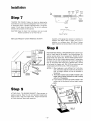
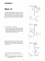
Step
POSITION AND INSTALL HEADER BRACKET. Opener" hardware in plastic bag will be needed in the following steps,, Determine vertical center" line of garage door+ Extend this onto
garage header wall above door+ Position header bracket centeron-center with this line at height approximately 2 inches above
the high arc point (this is high point of travel of top edge of
door as illustratedL Mark either' pair of bracket holes - vertical
or horizontal on header" watlo Drill 3/16 inch pilot holes and
instatl bracket with 5/16 inch by 1-7/8 inch lag screws,.
GARAGE
HEADER
" +._
HEADER
BRACKET
Step
8
_"_
LAG SCREWS
NOTES: t, When headroom is not sufficient for 2 inch clearance, the bottom edge of bracket may be placed at
high arc height. Bracket can also be attached to
the ceiling+
2,, The header bracket must be rigidly fastened to the
header' walt or ceiling. Reinforce the wall or ceiling
with a 2 x 4 if necessary.
& If it is necessary to fasten the header bracket to the
ceiling, use the horizontal (left and right) bracket
holes°
9
PIN
ATTACH RAIL TO HEADER BRACKET: Place operator on
packing material° Raise Tee rail until sprocket bracket joins
header bracket, Align the bracket holes, Attach with 3/8 inch
by 3 inch clevis pin, Secure with cotter pin+
PIECE
OF'
Installation
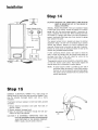
POSITION
THE
OPERATOR:
Raise operator
onto
a stepladder,
Open the garage door,, Place a 2x4 on edge along top section
door, Rest the Tee rail on the 2x4 as illustrated
NOTE:
A 2x4 is convenient
for establishing
an ideal door-torail distance,
It is not a necessity where headroom
is
insufficient,,
weight
SECURE
tration)
THE
OPERATOR:
between
operator
Measure
and joist,
distance
or other
("L"
angles,. Fasten
3/8 inch by 7/8
hanging
3/t6
inch
pilot
with
5/16
inch
lag screws.,
Lubricate
ceeding,
to operator
precautions
and doors
with
against
damaging
sup_J
chassis with
holes
bottom
Use tube
in roof
surface
supports,
of
Tee
Fasten
rail
of rail grease included
brackets
before
pro-
in the hard-
BEND
AS
ware package
CUT
Step
FASTEN
Flat
Washer
center
Reinforcing
Board
12
DOOR
with
below),
Carriage
Bolt
light
windows,
inch screws, and 3/8 inch nuts and lock washers.,
Drill
NOTE:
brackets
Take
doors,
in illus-
garage roof
port
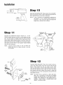
Cut both pieces of hanging bracket just beyond selected
holes
Notch bracket ends with hack saw.. Bend ends to form
desired
of
Align
either
top
Drill
5/16
BRACKET:
inside
vertical
bracket
and bottom,
inch
diameter
ears
Place
door
bracket
center
line
of door
with
top
rollers
or left and right
holes
in door
bracket
center-on-
(also see note
of
door
Mark
holes on door,
(or center
stile}
where
door bracket
holes were marked_ Bolt bracket
in place with
two 5/16 inch by 2_t/2 inch carriage bolts, and two 5/16 inch
loci< washers and nuts,,
Door
Bracket
NOTE : Use center stile on aluminum or light steel doors,
Where this is impractical; use the heavy flat washers
between bolt head and door, In such case also, REINFORCE THE INSIDE OF THE DOOR WITH A
BOARD 1 INCH THICK, 6 INCHES WIDE AND
ABOUT 12 INCHES LONG,
-9-
installation
Step
1:3
-x
/
Cotter
Pin
--
DETERMINE
cord
DOOR
through
end through
Remove
ARM
red handle
hole
plastic
LENGTH:
Thread
and secure with
in release arm of trolley,
carrying
strap
from
arm to
door
bracket
with
3/8
Straight
one end of nylon
knot,_ Thread
Secure
straight
with
door
other
a knot
inch clevis
ti
a_m,. Place
one end of straight
door arm in slot in trolley and fasten with
3/8 inch clevis pin and cotter pin,. Fasten short end of curved
door
Release Arm
_-%---- Clevis
Pin
Door Arm
Door
/
pin and cotter
pin
Curved Door
Arm
o Push the garage door to "closed tight"
o Bring the two door arm sections together If holes (in each
section) line up, join the sections with two 3/8 inch by 7/8
inch bolts, lock washers and nuts. PUT BOLT HEADS ON
STRAIGHT
DOOR ARM SIDE Select bolt holes as far
apart as possible to increase door arm rigidity,, DO NOT
USE MORE THAN ONE SLOTTED HOLE,
318"" Nut
31a- \@_
Lockwasher
318"' x 7/8-' Bolt
If door arm holes do not line up when the two sections are
brought together, cross the door- arms in scissors fashion (see
illustration)
until a pair of holes (one in each section) line up,
insert a 3/8 inch by 7/8 inch bolto Secure "finger tight" with
lock washer and nut,
-- Straight Door
Arm
•
Pull the emergency
•
Bring the door
both bolts,.
NOTE:
release cord to disengage
arm sections
Sears Keylock
together
Release accessory
an outside
emergency
service entrance door',
access
trolley,,
and bolt securely
No., 64-6571
for
ga[ages
with
provides
without
a
-10-
_
Door Arm
instaJlation
COD_
o
LABEL
CAUTION:
SIGNAL
CODE LABEL
RECEIVER
OR
ADDITIONAL
MUST
BE MOUNTED
SMALL
CHILDREN.
OUT
PUSH
OF THE
BUTTON
REACH
OF
INSTALL
RADIO
RECEIVER:
There are installation
flanges
at both ends of the receiver, Attach the receiver to an interior
OPENER TERMINAL BLOCK
ooi
garage
cation
wall with the wood screw, s provided.
A convenient
lois alongside
the service door When installing more than
one receiver
prevent
in a garage,
interference
door
operator
The
receiver
place
them
as far apart
(also keep wires
from
as possible
receivers
to
to garage
far apart)°
BELL WIRE
terminal
attachment
receiver
SH
flange
and
operator..
wire ends.. Connect
BUTTON
ir
, k.... t
Extend
the
receiver
using
tf
after
itself,
the
belt wire
connecting
1/2
staples,
inch
of
on back
the
bottom
bag to connect
insulation
from
end of operaton.
and down
the
wall to the
staples provided°
operate
face
just above
in hardware
to terminals
electric
not
(under
wire
across the ceiling
insulated
front
is located
Remove
wires
wires
or does
lower
strip
Use bell
of
power,
from
the
door
the
unit,
opens
receiver
check
or closes
push
for
button
a short
by
on
in the
for example).,
RECEIVER TERMINAL BLOCK
t4K]UNTING
FLANGE
The garage door opener
can be activated
or
push
from
the
receiver
override
those from
NOTE:
A special
button°
a transmitter
security
as a safety
switch
locking
plug
ELECTRICAL
devices
the
on door
attached
POWER:
First,
have been removed
3-pronged
electric
make
certain
or disabled.
cord
into
a
I,
wiring
is necessary
the door
by external
be opened
from
all
Then,
3-wire
Remove
electrical
chassis°
2, Remove
vided
CAUTION;
local
codes, proceed
o
operator
3,, Make
to meet
attached
the
connection
3-pronged
permanent
cover
plate
from
back
of
cord,
connection
through
the
hole
pro-
in the top of the operator.
IT IS EXTREMELY
UN IT BE GROUNDED
LEAD
MENT..
PROVIDED
Install
IN THE
a shut-off
GR£EN
LEAD
IMPORTANT
USING THE
WIRING
switch
THAT
THE
GROUNDING
COMPART-
in the line.
-tl-
on
is in the
can not
signal,
signals
will
feature,
is provided
receptacle,
If permanent
as follows:
button
the receiver,. When the switch
The opener can be activated
receiver push button,
CONNECT
by a transmitter
Push
the
LOCK
side of
position,
radio
signals°
a key switch
or the
justment
Step
16
ADJUST
OPENER
ptete up and clown
door
if
LtMITS:
Run the opener through
a comcycle. Adjustments
are not needed when
opens and closes
door
does
not
completely.
close
completely,
lengthen
door
arm
as
required,
A,. Run
door
in UP direction.
nut adjustments
CAUTION:
Disconnect
Bo Remove
4 cover
ward
from
C. Adjustments
or' down
tion),,
power
screws
Do
before
limit
as follows:
cover is removed,.
as illustrated
are made
limit
by turning
shaft just
and
slide
not
run
large plastic
behind
nut retaining
in place must be loosened
CAUTION:
Proceed
cover
for-
chassis.
a threaded
The
If it does not open enough,
are necessary.
bracket
before
opener
limit
the motor
which
nuts up
SCREW_-20
(see illustra-
/
holds the nuts
nuts can be turned.
before
limit
nut
bracket
_/TO
is
REMOVE
COVER
secured in original positiom
1.
2.
3.
4.
The top nut controls closing limits_
The bottom nut controls opening limits..
One turn of the limit nut equals 3 inches of trolley travel.
All adjustments require complete turns.
D,. TO MAKE ADJUSTMENTS:
Slide bracket to the left
Loosen limit nut bracket screw..
1. To increase UP limits-turn
bottom nut upward.
2. To decrease UP limits-turn
bottom nut downward
3. To increase DOWN limits-turn
top nut downward°
4_ To decrease DOWN limits-turn top nut upward..
5. These procedures may require repetition before adjustment is complete..
TURN
NUT ONE COMPLETE
REVOLUTION
FOR 3 _ OF
TROLLEY
TRAVEL
E. When adjustments are complete, slide bracket to its original
position and TIGHTEN SCREW SECURELY before applying power'.
LIMIT
NUT
F.. Replace cover and 4 cover screws. Reconnect power_
CAUTION:
After an adjustment,
power is turned on.
the motor
will
_
PLASTIC
RETAINER
NUT
SHAFT
run when
\
If door reverses at end of downward travel, the door arm is
too long. Shorten it one set of holes _ a time until reversing
ceases.
\
\
!
[
_1_\
DOWN
LIMIT
During limit nut adjustment procedure, if door reverses before
completing travel cycle in either direction, also check:
1.. Excessive binding of door (check manually and correct)..
2. Force adjustments are too light_ Refer to Step 17..
-:;--
CAUTION:
If the
door opener
is installed
on a door
with a height greater than 6 feet, the "UP'"
limit
-12-
must be adjusted.
ustment
ADJUST
DOOR
FORCE:
Determine
that
door
force
is not ex-
cessive in down direction.. Grasp the door handle or the bottom
of the door as it is about halfway
through
downward
travel.
/
Normally
the door
should
reverse
by this
action.
If it is hard to hold, or doesn't
reverse, loosen the clown
screw one turn at a time until the door reverses normally.
CLOSE
means
FORCE
ADJUSTMENT
SCREW
it will
not
reverse when
A. Adjustment
door)°
labels
\
door
next
opens
B Tighten
climatic
CAUTION:
at the end of
"Close"
"Open"
to
force
force
screws.
and
screw
screw
Turn
closes
adjustment
a travel
cycle,
and will
obstructed.
screws are near center
as illustrated.
ing
reverse
moderately
force
This
is on
left
clockwise
without
screws
of upper
chassis
is on the right
by
side.
half
flanges
sicle (facRefer
turns
to
until
reversing
an added
half
turn
to allow
for
changes.
Door force
hardware.
is not to compensate for faulty door
\
OPEN
FORCE
ADJUSTMENT
SCREW
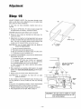
Step 18
INSTALL
Light
off
LIGHT
turns
automatically
available,
"Rough
*Use 100 watt
60 watt
LENS:
AND
LENS:
on automatically
Gently
about
Install
when
90 seconds
Service"
bulbs
a light
opener
after
should
turn
stops,
if
be used.
in Model
t39 653000
bulbs
in Model
139.653100
lens and insert
in socket.
It will
the opener
bulbs
squeeze
bulb*
starts.
USE
IOOWATT BULB
60 WATT BULB
tabs in slots in chassis.
Release pressure and lens will snap
remove lens, reverse this procedure
into
_--'_-_
place., To
-13
-
_'_""_
MODEL
139 65300
13965310
LENS
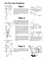
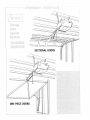
One Piece Door Installations
One Piece Door° Jamb Hardware°
Step 1
H orizonta| Track.
Highest Point
ofir_ave
_
,,,_. . ....... INSTALL
bag will
_
DOO\\_\
5/16"
LOCK
WASHER
///
TRACK
DOOR BRACKET:
(Hardware
in plastic
be needed in the following
steps). Determine vertical
center line of garage door, Position
door bracket center-on-center
with this line at leading edge of top of door (see illustration),
holes.
Drill
5/16
inch holes through
Mark outer
door top,
Fasten bracket with
washers and nuts,,
bolts,
5/16
inch
carriage
LEADING
TOP OF DOOR
\
lock
5/t6'
One Piece Door° No ]rack.
Jamb
Hardwares,
Highest Point of
of Travel
INSTALL
HEADER
center
of door
door. Reinforce
bracket support,
//
DOOR
/i/
4
BRACKET:
onto
garage
Extend
header
vertical
wall
above
header wall if necessary for header
A 2x4 or 2x6 will suffice,. Posi-
tion the header bracket according
to door type and
its arc of travel (see illustrations
at left edge of page)°
A_
//
line
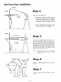
One-Piece
Door Without
Track:
Open door
to highest point
of travel, Measure distance
from top of door to floor,, Subtract
actual
height of door (top to bottom),
Remainder
is door rise (see column 1 of adjoining
chart),
Refer to chart for' setting height of header
bracket
above door, Place bracket
at referenced height and center-on-center
with
extended
vertical
center
line of door,
Mark
bracket
holes, Drill
3/16 inch pilot holes,
Fasten
bracket
with
5/16
by 1-7/8
inch
B_ One-Piece Door With Track: Position
header
bracket center-on-center
with extended vertical center line of door and approximately
2
inches above
the horizontal
tracks,
Mark
One Piece Boor,, No Track. Pivot
bracket
holes on wall
Drill 3/!6
inch pilot
holes.. Fasten bracket with 5/16 by 1-7/8 inch
lag screws,
Hardware,
Highest Point
of Travel
/
//
Step
3
DOOR
\,
ATTACH RAIL TO HEADER BRACKET: Place
operator on packing material.. Raise Tee rail until
sprocket bracket joins header b_acket. Align holes..
Attach with 3/8 inch by 3 inch clevis pin. Secure
with cotter pin..
//
PIVOT
-14-
I
h
_
H_'AD_R
LAG
SCREWS
_
BRACKET
Door'
Rise
In Inches
Iag
screws.
JAMB
HARDWARE
CARRIAGE
BOLT
Up to 4
4
to 8
8 to 12"
Location
Bracket
of Header
Above Door'
in I riches
10
15
20
*if door rise is greater than 12 inches, or
if low ceiling clearance doesn't allow
positioning header bracket as shown in
column 2 above, use the remote installation procedures on Page 17.
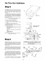
One Piece Door InstaHiations
POSITION
A
THE
OPERATOR:
One-Piece
Door Without
Track:
Raise motor
end
of opener
to a height
equal to door bracket
with door open. Support opener with stepladder.
For maximum
efficiency,
do not secure the
operator
more than 2 inches higher than this,.
B One-Piece
Door
With
Track:
Raise motor
end of
opener
to height
above and paraflel
to
zontal tracks.. Support it with stepladder.
\\-\\,
_
HEADER
hori-
BRACKET
SECURE
THE
OPERATOR:
Measure
distance
("L"
in iIfustration)
between
operator
and joist, or other
garage roof support., Cut both pieces of hanging brackTRACK
et just beyond selected holes,. Notch bracket ends with
hack saw. Bend ends to form desired angles. Fasten
hanging brackets
to operator
chassis with 3/8 inch by
7/8 inch screws, and 3/8 inch Iock washers and nuts
Drill 3/16 inch pilot holes in roof supports
Fasten
brackets wlth 5/16 inch lag screws.
NOTE:
Lubricate
bottom
proceeding.
in hardware
STR UCTURAL-_
MEMBER
surface
Use tube
box,
of Tee rail before
of rail grease included
P
!;l
HANGING
INSTALL
RADIO
RECEIVER:
Refer
to
Step
14
Page 11,
\
Step
CONNECT
Page 11.,
BEND
AS
NECESSARY
-15-
?
ELECTRICAL
POWER:
Refer to Step 15,
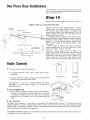
One Piece Door Installations
Step
8
SET OPENER
LIMITS:
(1) Using the radio controls,
run trolley
back to the "up" limit near motor end of
unit,
Disconnect
electric
power,
Remove
4 cover
screws
and slide
cover
forward
from
chassis
as
illustrated_
(2) Adjustments
are made by turning
large plastic
limit nuts up or down a threaded shaft just behind the
motor (see illustration),
The limit nut retaining
bracket which holds the nuts in place must be loosened before nuts can be turned°
CAUTION:
Do not run opener before limit nut
et is secured in original
position_
•
The top
nut
•
The bottom
=
One turn
travel,
•
All
controls
nut
of
closing
controls
limit
adjustments
nut
equals
require
limit
nut
complete
Loosen
bracket
_TO'REMOVE
COVER
limits.
3 inches of trolley
(3) Reset top nut (down
limit)
(counterclockwise)..
Reset bottom
nut (up limit)
(clockwise),
Slide
brack-
limits,
opening
TO MAKE ADJUSTMENTS:
screw, Slide bracket to left,.
SCREW _-20
to
turns,,
limit
nut bracket
6 turns
3 turns
right
and
to
to
TURN
NUT ONE COMPLETE
REVOLUTION
FOR 3'* OF
TROLLEY
TRAVEL
right
left
tighten
LIMIT
screw,,
SCREW/
Replace chassis cover,,
Reconnect
power.
CAUTION:After
when
an adjustment,
power is turned
NUT
RETAINER
BRACKET
the motor
on,.
wilt
O
run
PLASTIC
NUT
SHAFT
0
OOWN
L_MIT
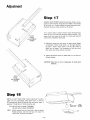
Step
9
CAUTION:
CONNECT
DOOR
ARM:
Thread
one end of nylon
cord through red handle and secure with knot. Thread
other end through
hole in release arm of trolley.
Secure with
knot,, Remove
plastic carrying
strap from
straight door arm.,
Using 3/8 inch clevis
pin, connect
one end of
straight door arm and door bracket.
Secure with cotter pin, Use other 3/8 inch clevis pin to connect short
end of curved door arm to tro!ley,, Secure with cotter
pin..
5/16"
LOCK
WASHER
5t16"
NUT
,318""NUT
WASHER
Close the door tight, Bring the two door' arm sections together,. Bolt the sections if the holes line up,.
Use 3/8 inch by 7/8 inch bolts, and 3/8 inch lock
washers and nuts, Select bolt holes as far apart as possible to increase door arm rigidity,
DO NOT USE
MORE THAN ONE SLOTTED
HOLE
If the door arm holes do not line up to permit
bolting, follow the instructions in Step 13, Page 10.
If the door opener is installed on a door
with a height greater than 6 feet, the "UP"
limit must be adjusted.
_//_
/
/
5tl 6"
CARRIAGE
BOLT
-16 -
/
3/8" BOLT
One Piece
oor Instal
Otis
ADJUSTMENTS:
If, after installation
not open or close satisfactorily,
follow
and 17 on Pages 12 and 13,,
of opener, door does
adjustment
steps 16
P
INSTALL
REMOTE
INSTALLATION
LIGHT
CE I LING
Refer
to Step
T8, Page 13,
INSTALLATION
PROCEDURES:
(1)
Fasten
header bracket
to a suitable
support
on ceiling
(a 2x4 or
2x6 reinforcing
plank nailed to joists,
for example),
Tile
support
location
should be the most convenient
in line with
SUPPORT
HEADER
LENS:
PROCEDURES
REMOTE
IdIGH
POINT
or- TRAVEL
AND
BRACKET
the door bracket
and further
inside
the garage than tile
highest point of door travel.
(2) Follow
procedures
of Steps 3,4,5,6,
and 7 by which
[_<
garage door opener is fastened to header bracket and ceiling
Increased
distance
between
trolley
and door
bracket
is
joined
by 1 inch thin
walled
electrical
metallic
tubing
(EMT)
conduit
available at most electrical
supply or hardware stores,
(3) Run trolley
to "Down"
limit,, Close door, Measure
!
I
t
DIAMETER
THIN
WALLEO
EMT
m
distance
bracket
LJ
'\o o o o o o__...2jo
_cuT
between
holes for door arm clevis
and trolley
Subtract
24 inches,,
pins
in door
Remainder
is desired
length
of EMT,, Cut EMT
length. Insert long end of curved door arm, and one
straight
door arm into ends of conduit
at least 4
Flatten
EMT at each end where bolt hole is needed
o o o
AsREQ'D--J
taching to door arms, Drill 3/8 inch
inch by 7/8 inch screws, and 3/8 inch
to this
end of
inches,,
for at-
holes, Fasten with 3/8
lock washers and nuts,,
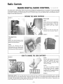
Radio Controls
1
The radio
control
=' A portable
automobile
has two
basic components:
transmitter
which
sends a coded
signal from
an
TRANSMITTER
RECEIVER
= A receiver which is attached to a garage wall. It receives the coded
signal, and activates the garage door opener..
FOR
SERVICE
-
DO
CONTROLS,
If service
page 23 of manual,
NOT
ATTEMPT
becomes
REPAIR
OF RADIO
necessary, see instructions
on
CovBr
2 THE TRANSMITTER
=
The transmitter,
including
contained
in an attractive,
is provided
transmitters
a battery
and push button
switch, is
high4mpact
plastic case, A metal clip
for attaching
the
can be installed
"_
I
,'_
".L .....
Battery
unit to an auto sun visor, Separate
in each of the vehicles using the
garage
3 THE
The
BATTERY
battery
should
weather
conditions°
weather
failure
mercury
batteries
Clip
operate
To
for
avoid
a time
unexpected
equal
to
battery
its normal
shelf
failure,
replace
fife (approximately
it at least once
one year),
a year.
This
There
may
be shortened
is Iess possibility
of
o
TO CHANGE
new battery
if a new battery
is installed
assure the most reliable
BATTERY-Remove
to connector.
Replace
cover
in autumn,
In regionswhere
temperature
extremes
are below 0
by
cold
O
F, and above 90
F,
operation.
as indicated
in accompanying
cover,
-17-
illustration
Disconnect
battery
from
connector.
CEip
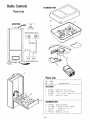
Radio Controls
SEARS DiG|TAL
The coded
signal
in Sears Digital
is a flat blade screwdriver
switch
block.,
ranged
into
Changing
5t2
Radio
Controls
RADIO CONTROL
can be changed
Choose your own code by changing
the ON-OFF
position
of only
easily
position
one switch
without
the aid of a serviceman,,
of ON-OFF
makes
PAT
A PUEOFOR
switches
an entirely
numbered
different
code
The only
1 through
tool
needed
9 on the code
The 9 switches
can be ar-
code combinations,
OPENING THE RADIO CONTROLS
FIGURE 1
RECEIVER
STEP 1
Remove receiver cover by gripping top
lip of cover with ends of fingers and
pulling
outward
(Figure
1) Do not
move printed circuit
board compo nents
STEP 2
Disconnect
connector
FIGURE
the two wire,
24 volt,
AC
from the receiver (Figure 2)
2
FIGURE
4
TRANSMITTER
STEP 3
Remove visor clip from back of transmitter by prying it away from the case.,
Remove the screw (Figure 3),
STEP 4
Carefully
turn transmitter
case over
(with pushbutton
up} Remove top of
transmitter
case (Figure 4), Be careful,
Do not move circuit board components
FIGURE
3
HOW TO CHANGE THE CODE SWITCHES
FIGURE
5
STEP 5
Place the receiver cover with
_@_:
_:;,::_i_
,
its printed
circuit
board alongside that of the
transmitter
(Figure 5),. Code switch
blocks should be at the bottom (right
side up for reading).,
STEP 6
Use a pencil
or smewdriver
to change
switch positions (Figure 6). To change
a code, press one or more switches
either ON orOFF, Changing at! switches
to OFF wil! constitute a code
FIGURE 6
IMPORTANT
tional
into
NOTE:
transmitters
The
piace,_ The lock switch
mitter,.
new code setting
used to operate
Please keep this
the door,
on some
instruction
receivers
must
be exactly
Reconnect
(built
sheet for future
the
the same in both
AC connector
into side of case) must
reference,,
-18-
the receiver
and transmitter,
to the receiver
be unlocked
also, in any addi-
and snap the receiver
(Down
position),.
cover
Reassemble
back
trans-
TRANSMITTER
RECEIVER
r
CODE
I
LABEL
SIGNAL
CODE LABEL
OPENER TERMINAL
BELL
PUSH
BLOCK
ooI
WIRE i
BUTTON
RECEIVER
TERMINAL
BLOCK
FLANGE
Parts List
KEY
NO,
PART
NO,
[JESCRIPTION
RECEIVER
1
2
IB1436
IA1385S
Receiver
Receiver
case assy.
circuit board
IAI385Y
IA1492
with cover (Specify S
Receiver cover
J3
TRANSMITTER
4
5
6
7
-19-
IA1489
IAI138S
lAII38Y
2B126
57-6423
Case assembly
Printed circuit board
(specify S or Y)
Clip,visor
Battery, 9 volt
or
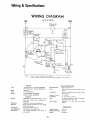
Wiring & Specifications
WIRING
DIAGRAM
117 V AC
LINE
60Hz
NEUT.
CONVENIENCE
OUTLET(X)
WHt
_,,C_r
I
I BUTTON
,'¢7
LAMP DELAY
SWITCH
YEL
CRK.
PSC
MOTOR
fiRK,
..=J
RELAY
iMPULSE
W/THERMAL
OVERLOAD
j
DOWN
LIMIT
OBSTRUC
0
SWITCH
I
REVERSE
DISABLE
CLASS
I
I
BLK
q
LSW_TCH j
t
I
I
UF
24vAC
270 .rz
YEL L
NOTE
:
I
PARTS(X)AND(Y)ffOT
2
SOME
USED _N ALL
VERSIONS
OF MANUAL
RESET
MODELS
SUTTON
HAVE
TERMINALS
MOTOR
Type
.....
Speed
Volts
t/3
.....
Cur_nt
run
.......
Speed Reduction
Belt and pulley
1/4 HP capacitor run (Model
t,0OO rpm
t t7 VAC 50/60 Hz
139653100)
Drive
Roller chain
Tee rail
Lubrication
Motor
4 5 emps
(Model
139653000)
26
(Model
139653100)
amps
Pushbutton
Electrical
........
reverse in down
Limit
Device
Limit
Adjustment
StertCireuit
Independent
.........
Motor'
.......
reversal
Length
....
overload
Traveling
Low
radio
protector
nuts on sprocket
voltage
cent! el
direction
Auto-
directions
pushbutton,
of Travel
Trave!
Rate
Lamp
,,
, ,
Linkage
adjustment
and low
,
8
6 -
8 inches
when
per
door
key
Length
switch
or
- 20-
(overall)
Headroom
Required,
Weight
......
Adjustable
release
10½
trolley
Drive
on steel
shaft
bronze
off
approxio
cord
trolley
second
starts
in travel
90 seconds after
"'L"
DIMENSIONS
shaft
piece
feet
voltage
nuts
two
lubricated
0 On
8, 1 : 1
and
bearings
mate]y
on
Door
up and down
self
oifite
both
pushbutton
wiring
Circuit
actuated by limit
.........
MECHANISM
139.653000)
matic
door
obstruction
Mechanical
REVERSED
(Model
SAFETY
Personal
2&3
DRIVE
HP capacitor
-J
BLK
feet
2 inches
60 pounds
arm
stop
pull
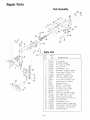
pair Parts
Rail AssembBy
2O
10
11_
12_
_6
4
\
I
8
7
11> ji PartsList
/
KEY
NO.
I
2
3
4
5
6
7
8
9
iO
II
12
13
14
15
16
17
18
19
20
21
22
23
24
25
26
27
- 21 -
PART
NO.
146A19
12A129
146A30
133A29
216A26
IA452
171A88
171AZ4
183B35
IA955
146A21
91A7
26A39
I09AII
IA1428
IB1435
133A87
2B123
171A191
183B36
171A184
133A28
216A25
12A197
178B22
178B23
12B198
DESCR IPT ION
Pin,cotter
Bracket,header
Pin,clevis,3/Sx3
Nut,3/8-16
Lockv,asher,3i8
Sprocket bracket assy.
Screw,hex,5i16xl-7/8
Screw,hex,3/8-16xl
Tee rail,header end
Trolley,outer
assy.
Pin,clevis,3!Sxl-I/16
Handle,pull
release
Rope,braided
Master link,chain
Roller,chain assy°
Trolley,inner
assy.
Locknut, I/4-20
Tee rail,center brace
Carriage bolt, I/4-20
Tee rail,motor end
Screw,Sems,5/16-18xl/2
Nut,5/16-18
Lockwasher,5/16
Bracket,cha in retainer
Strap,door arm,straight
Strap,door arm,curved
Bracket,door
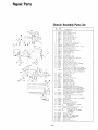
Repair Parts
ChassisAssemblyParts List
KEY
f'lO.
3-L L_
.__=___r5_
2
_.__]5=._
- ,8
58
....1455 ............
'_-"-_II _<_ ,\',Ltt
. t, -_z
53 ,
50 _:,#"
"'
"'I
c.,14 E
. <
1_. _ ,51,11. =.,.41
........... \
r
_
'
11
'
I_/'1
_
--I
>......
/1_
i
..........
i
....._-_,.
1
.:,_ _>7,
"
/,\
I
;;"=i ..............r.........
+'-1]
]
............
.fill
<.-"_:
t7
I
"
18
9
,,
. { :-42
t
r16\
,.,I
i 17
<--'f:
:,
LI._
I
2
3
4
5
6
7
8
9
I0
II
12
13
14
15
16
17
18
19
20
21
22
23
,_2.4
25
26
27
28
PART
IlO,
171A183
31B129
31B127
171A74
IA950
216A95
158A30
BIA9
IB948
I 77A73
133AI06
216A I00
IIAI3
171A182
37D61
133A109
IA989
204B77
133A I05
IAI081
17tAI84
lIAl2
216A96
158A31
IAI481
12C 196
12A201
123D17
DESCRI PT _Of'i
Screw,BFx3/8
Cover,reverse
Swi'!'Ct_
Cover,sprocket
Screw,hex,BBx3/8
Shaft
and
Washer,shim,
"E"
sprocket
I/2"
ring_Ii2"
assy
I .D
shaft
i diet
Sprocke'l,
Lever,actuator
_v¢itch
Spring,switch
adjustment
I4ut,square,5i16-18
;'lasher,shim,3/4"I
D. xi"O.O.x
i_
,_._
22-_'26
.......
4 F:';
Y
:._
;
123D16
Screw,5i16-18x2-1i2
Chas_is,componeni
T inne rman,
mounting
I/ 4-20
Light
socket
Transformer
assy
Nut_sgeciel
limit
Switch,limit
_ssy.
Screw,washered,5/16-18x9i16
Bear
ing,3/B"i
D,
Washer,sh
Push
im,3/8"
on
Pulley
I, O,
ring,318"
a_sy+8
shaft
65
Bracket,shaft
pitch
Bracket,nut
retainer
Motor
for
assy
Motor
i_<I
-_°,
.................
::9:
...............
_9'<"
"><
3_
171A58
144B6
20A3
31DI06
171A175
108C6
IA35
171A51
2A150
133A49
12A194
30A205
assy.
Model
for
Model
6
139,653100,
amps;llTVAC;60
Pulley,drive
Belt,Vee,3L-31
Cover,chassis
Screw,hex,ii4-2Qxli2
Lens,tamp
cover
Light
delay
Screw_hex_6Tx3i8
Terminal
assy.
board
assy
T innerman,type
8U
tot
Bracket,capaci
mounti
ng
stari'
Capacitor,motor
for
Model
653000,Rating;50-60MFD;250VAC
Capacitor,motor
t39
34
139,653000,
amps;II7VAC;50/6OHz
Screw,set,5!16-1B
139
30A218
eLemeter
re'raining
Rating:Ii4hp;2
29
30
31
32
33
34
35
36
37
38
39
40
010
Bearing,to_,Ii2"l,O,
Rating:Ii3hp;,l,5
f7 7: 4o
assy
653100
,II
216AI0
Lockwesher,
42
IA1375
Wiring
,13
12A218
Bracket,reset
for
star#
Model
box
,Rat ing:36-42MFD;250VAC
internal
tooth
,No,6
assy
for
button
Model
139.653000
44
45
46
47
48
49
f80B48
171A189
160B27
12B208
171A15
iBOB50
Reset
button
for
I,_del
139,653000
Screw,BBxl
Relay_impulse
Bracket,relay
mountin
Screw,sems,8-32x3i16
Reset
button
9
for
Model
139,653100
50
12B225
INSET
Bracket,reset
Model
51
133A43
button
Tinnerman
nut
for
139,653100
52
53
54
55
56
57
58
-22 -
31FI03
203A68
IAI070
30A219
IA942
28A60
26A42
Wiring
box cover
Terminal
board
Resistor,2?O
Capacitor,,22
ohms,2
watt_
MFD;2OOVDC
S_iteh,reverse
assy,
Cable,clamp
Cable,line
_er
139653100
cord,4
ft.
Model
Hz
SAVE-A-CALL BY CHECKINGTHESE BASIC POINTS.
INSTALLATION GUARANTEED BY THE INSTALLER.IF IT iS A
SELF-INSTALLATION, CORRECTIONSWILL BE MADE ON A
CHARGE BASIS.
O
WHEN DOOR OPENS
t
Check pushbuttons
ding
pushbutton(s}
staples, etc,
WHEN
DOOR
WILL
NOT OPEN WITH TRANSMITTER(S).
NOR WALL
OR RECEIVER
PUSHBUTTONS:
1. Check to be certain
that NO LOCKS
OR BOLTS
are preventing the door from opening,
2 Check for tripped
circuit
breaker or blown fuse..
3 Check to be certain any waff switch used to supply power to
the opener is in "ON"
position.
4
Check wire from wall receiver
broken where wire terminates)
if the unit has been operated
5
to opener
for break
numerous
times
2.
(generally
WHEN
DOOR
DOES
PLETELY:
t
Check to be certain
STOPS
preventing
WITHTRANSMITTER,WORKS
OR SECOND
TRANSMITTER:
pletely.
2., Opener
1. Check
battery,
If two transmitters
are used, check by exchanging with "working"
transmitter.,
2. if wall receiver is equipped
with LOCK SWITCH,
check to see
that the switch
is "in the "OFF"
position
(away from
lock
labett.
WHEN
DOOR
REVERSES
FOR
NO APPARENT
Increase
tension
opener
chassis.
ment instructions
of FORCE
Check
SCREW(S)
label
and
WHEN
ATOR
REASON:
located
Owner's
at side(s)
Manual
limit
Controls.
set your own
in the Owners Manual
NOT
t.
setting
WHEN
FROM
1
2
3
of
LIGHT
DOES
tS ENERGIZED:
Check
light
QUITE
OPEN
OR
there are NO PHYSICAL
the door
from
opening
needs
NEW
INSTALLATIONS
your Owners Manual,
1. Check for DOOR BALANCE';OR
BINDING
Disconnect
door
from opener
by pu!_;,_g RED HANDLE.
Open and close door
manually,
Door ,should
operate
smoothly
and reasonably
easy. If door is binding,
check for physical
binding
at jamb,
track,
etc, If service is needed, call a garage DOOR
service
company.
2
Check to determine
if a SEARS
garage door opener in the
neighborhood
uses the same radio code. If same IDENTICAL
codes exist, bring
BOTH
the receiver
AND
transmitter
to
SEARS service to obtain a different
code., if your unit features
the Sears Digital
Radio
agcording
to instructions
in succession,
a thermal
overload
switch
in the motor
may have tripped
Allow several minutes for cooling before operation
is repeated.,
6,, Check reset button
on back of operator
chassis
WHEN DOOR WILLNOTOPEN
OK, FROM PUSHBUTTONS,
AND/OR
CLOSES BY ITSELF:
and wiring
(receiver
to opener}
by prodand wiggling
wire,
especially
under
adjustment,
See
NOT
GO
code
COM-
UNINTENDED
or closing com-
ESPECIALLY
ON
instruction
WHENEVER
THE
in
OPER-
bulb(s}
THERE
WITHIN
IS INSUFFICIENT
THE CAR:
TRANSMITTER
Check battery,
Change transmitter
location
in car.
Check antenna
to be certain
connection
for adjust-
CLOSE
easy-to-follow
ON
pew
proper,THERE
IS NO ANTENNA
with
RANGE
or installation
Digital
Radio
is
Controls.
CAUTION:
• OPERATE DOOR ONLY WHEN FULLY VISIBLE, PROPERLY ADJUSTED,
e DO NOT PERMIT CHILDREN TO PLAY IN AREA OF DOOR,.
e READ THE INSTRUCTION
MANUAL,.
THINGS
TO REMEMBER
DOOR
nected
(ie
DISCONNECT
from
power
failures)
trolley
It will
reactivated
Your
when
_farage door
manual
down
when
LUBRICATION
every
is
3
-
months
Oil
LUBRICATION
surfaces
door
Use
_
rollers,
silicone
Clean
ot" tee rail once
bearings
lubricant,
and
a year
reg_;ase
or
top
and
light
and
IN
CASE
SERVICE
OF
RADIO
RECEIVER
CONTROL
COVER
ONLY
PROBLEMS.
WITH
REMOVE
ATTACHED
-
Make certain
held fast(ie
(see Things
Check
door
replace
If one
BALANCE
-
best when
the
by
connect)
A door
opening
travel
while
ments
are needed,
RECEIVER
PRINTED
CENTER.
_23 -
is not locked
down.
Disconnect
door from
Raise
manually
is broken,
The opener's
door
door
have
a garage door
auLomatic
is in good
and closing
is balanced
being supported
COVER
CIRCUIT
dool
ice)
it
works
manually
snow,
1o Rernember)
springs
DOOR
Use rail grease sup-
plied
BRING
opener
tied to the
the opener
SPRINGS
or oiherwise
is necessary
on the red handle
automatically
DOOR
can be discon-
operation
company
hinges
oil
bottorn
Pull
reconr'ect
DOOR
OPENER
,, ,
-
the opener
AND FREE OF OBSTRUCTIONS,
the
tt
system
is tested
(see Doo_
il stays
solely
by itsspiings
Dis.
in any pointof
If adjust-
company
BY UNLATCHING
AND
(toot
when
call a gmage door
BOARD
safety
balance
TRANSMIT
AND
UNPLUGGING
I E:R TO A SEARS
HOW TO ORDER
REPAIR
PARTS
The Model Number' will be found on the label attached to the back of the
opener.. Always mention the Model Number when requesting service or repair
parts for your SEARS ELECTRONIC
GARAGE DOOR OPENER°
All parts listed herein may be ordered through SEARS, ROEBUCK AND CO.
When ordering parts by mail, selling prices will be furnished on request, or
parts will be shipped at prevailing prices and you will be billed accordingly.
WHEN ORDERING
REPAIR PARTS, ALWAYS
INFORMATION
AS SHOWN tN THIS LIST:
1. The PART NUMBER
2. The MODEL NUMBER
GIVE
THE
FOLLOWING
3o The PART DESCRIPTION
4, The NAME of the ITEM
Your Sears merchandise takes on added value when you realize that Sears has
over 2,000 Service units throughout
the country, Each is staffed by Searstrained, professional technicians using Sears approved parts and methods.
IMPORTANT
NOTE: Include Radio Control code Wh_a ordering radio control parts. If you suspect radio malfunction, take radio controi: to the nearest
SEARS Service Center for test and/or low cost exchange.
FEATURES
OF YOUR OPENER
Opener light-will
convenience,,
2
Automatic
either
3
Reverse
on and off
reverse-door
up or down
Emergency
reverses
automatically
automatically
for your
when
safety
and
obstructed
in
direction,.
disable-automatic
inches of down
etc,
4,
turn
reverse
t, avel to prevent
disconnect-pull
feature
nuisance
is disabled
in
last
few
reversals due to ice, snow,
cord disconnect
permits
manual
door
operation.
5,. Automatic
ation
6,
Digital
reconnect-trolley
when opener
Radio Controls-Coded
SEARS, ROEBUCK
Part No,, 114A351D
is energized
halves
reconnect
after emergency
for
automatic
oper-
disconnect,_
signal can be changed easily
by owner.
AND CO.. BSC 41-3 SEARS TOWER
CHICAGO,
ILLINOIS
60684