1
Vigor2960
Dual-WAN Security Firewall
User’s Guide
Version: 1.3
Firmware Version: V1.0.9
(For future update, please visit DrayTek web site for further information)
Date: October 29, 2014
ii
Vigor2960 Series User’s Guide
Copyright Information
Copyright
Declarations
© 2014 All rights reserved. This publication contains information that is protected by
copyright. No part may be reproduced, transmitted, transcribed, stored in a retrieval
system, or translated into any language without written permission from the copyright
holders.
Trademarks
The following trademarks are used in this document:
Microsoft is a registered trademark of Microsoft Corp.
Windows, Windows 95, 98, Me, NT, 2000, XP, Vista and Explorer are
trademarks of Microsoft Corp.
Apple and Mac OS are registered trademarks of Apple Inc.
Other products may be trademarks or registered trademarks of their respective
manufacturers.
Safety Instructions and Approval
Safety
Instructions
Read the installation guide thoroughly before you set up the router.
The router is a complicated electronic unit that may be repaired only be
authorized and qualified personnel. Do not try to open or repair the router
yourself.
Do not place the router in a damp or humid place, e.g. a bathroom.
The router should be used in a sheltered area, within a temperature range of +5 to
+40 Celsius.
Do not expose the router to direct sunlight or other heat sources. The housing and
electronic components may be damaged by direct sunlight or heat sources.
Do not deploy the cable for LAN connection outdoor to prevent electronic shock
hazards.
Keep the package out of reach of children.
When you want to dispose of the router, please follow local regulations on
conservation of the environment.
Warranty
We warrant to the original end user (purchaser) that the router will be free from any
defects in workmanship or materials for a period of two (2) years from the date of
purchase from the dealer. Please keep your purchase receipt in a safe place as it serves
as proof of date of purchase. During the warranty period, and upon proof of purchase,
should the product have indications of failure due to faulty workmanship and/or
materials, we will, at our discretion, repair or replace the defective products or
components, without charge for either parts or labor, to whatever extent we deem
necessary tore-store the product to proper operating condition. Any replacement will
consist of a new or re-manufactured functionally equivalent product of equal value, and
will be offered solely at our discretion. This warranty will not apply if the product is
modified, misused, tampered with, damaged by an act of God, or subjected to abnormal
working conditions. The warranty does not cover the bundled or licensed software of
other vendors. Defects which do not significantly affect the usability of the product will
not be covered by the warranty. We reserve the right to revise the manual and online
documentation and to make changes from time to time in the contents hereof without
obligation to notify any person of such revision or changes.
Be a Registered
Owner
Web registration is preferred. You can register your Vigor router via
http://www.draytek.com.
Firmware & Tools
Updates
Due to the continuous evolution of DrayTek technology, all routers will be regularly
upgraded. Please consult the DrayTek web site for more information on newest
firmware, tools and documents.
http://www.draytek.com
Vigor2960 Series User’s Guide
iii
European Community Declarations
Manufacturer:
Address:
Product:
DrayTek Corp.
No. 26, Fu Shing Road, HuKou Township, HsinChu Industrial Park, Hsin-Chu County, Taiwan
303
Vigor2960
DrayTek Corp. declares that Vigor2960 of routers are in compliance with the following essential requirements
and other relevant provisions of EC, Directive 2004/108/EC.
The product conforms to the requirements of Electro-Magnetic Compatibility (EMC) Directive 2004/108/EC by
complying with the requirements set forth in EN55022/Class A and EN55024/Class A.
The product conforms to the requirements of Low Voltage (LVD) Directive 2006/95/EC by complying with the
requirements set forth in EN60950-1.
Regulatory Information
Federal Communication Commission Interference Statement
This equipment has been tested and found to comply with the limits for a Class A digital device, pursuant to Part
15 of the FCC Rules. These limits are designed to provide reasonable protection against harmful interference in a
residential installation. This equipment generates, uses and can radiate radio frequency energy and, if not installed
and used in accordance with the instructions, may cause harmful interference to radio communications. However,
there is no guarantee that interference will not occur in a particular installation. If this equipment does cause
harmful interference to radio or television reception, which can be determined by turning the equipment off and
on, the user is encouraged to try to correct the interference by one of the following measures:
Reorient or relocate the receiving antenna.
Increase the separation between the equipment and receiver.
Connect the equipment into an outlet on a circuit different from that to which the receiver is connected.
Consult the dealer or an experienced radio/TV technician for help.
This device complies with Part 15 of the FCC Rules. Operation is subject to the following two conditions:
(1) This device may not cause harmful interference, and
(2) This device may accept any interference received, including interference that may cause undesired operation.
More update, please visit www.draytek.com.
iv
Vigor2960 Series User’s Guide
Table of Contents
Chapter 1: Introduction .....................................................................................................1
1.1 Web Configuration Buttons Explanation ...................................................................................... 1
1.2 LED Indicators and Connectors ................................................................................................... 2
1.3 Hardware Installation.................................................................................................................... 5
1.3.1 Network Connection ................................................................................................................5
1.3.2 Wall-Mounted Installation ........................................................................................................6
Chapter 2: Initial Configuration ........................................................................................7
2.1 Changing Password ..................................................................................................................... 7
2.2 Quick Start Wizard........................................................................................................................ 9
2.2.1 Step 1 – Specifying the WAN Profile .......................................................................................9
2.2.2 Step 2 - Configuring the Selected Protocol ...........................................................................10
2.3 Register Vigor Router................................................................................................................. 17
Chapter 3: Application and Tutorial................................................................................21
3.1 How to Build SSL VPN with RDP Service in the Browser via Logging in Router's HTTPS Server?
.......................................................................................................................................................... 21
3.2 How to Configure OSPF?........................................................................................................... 26
3.3 How to Configure LAN to LAN IPsec Tunnel between Vigor2960 and Other Router ................ 33
3.4 CVM Application - How to manage the CPE (router) through Vigor2960? ................................ 36
3.5 CVM Application - How to build the VPN between remote devices and Vigor2960? ................ 41
3.6 CVM Application - How to upgrade CPE firmware through Vigor2960? .................................... 44
3.7 How to use High Availability for Vigor routers? .......................................................................... 50
3.8 How to Configure DNS Inbound Load Balance on Vigor 2960? ................................................ 55
Chapter 4: Advanced Configuration...............................................................................59
4.1 WAN ........................................................................................................................................... 59
4.1.1 General Setup........................................................................................................................60
4.1.2 Inbound Load Balance...........................................................................................................81
4.1.3 Switch
...............................................................................................................................86
4.2 LAN ............................................................................................................................................ 90
4.2.1 General Setup........................................................................................................................90
4.2.2 PPPoE Server......................................................................................................................103
4.2.3 Switch
.............................................................................................................................108
4.2.4 Bind IP to MAC ....................................................................................................................114
4.2.5 LAN DNS 117
4.3 Routing ..................................................................................................................................... 120
4.3.1 Load Balance Pool...............................................................................................................120
4.3.2 Static Route .........................................................................................................................124
4.3.3 Policy Route.........................................................................................................................130
4.3.4 Default Route.......................................................................................................................145
4.3.5 RIP Configuration ................................................................................................................146
Vigor2960 Series User’s Guide
v
4.3.6 OSPF Configuration.............................................................................................................148
4.3.7 BGP Configuration...............................................................................................................150
4.4 NAT........................................................................................................................................... 155
4.4.1 Port Redirection ...................................................................................................................155
4.4.2 DMZ Host .............................................................................................................................159
4.4.3 ALG
.............................................................................................................................162
4.5 Firewall ..................................................................................................................................... 164
4.5.1 Filter Setup ..........................................................................................................................164
4.5.2 DoS Defense .......................................................................................................................190
4.5.3 MAC Block ...........................................................................................................................193
4.6 Objects Setting ......................................................................................................................... 195
4.6.1 IP Object .............................................................................................................................196
4.6.2 IP Group .............................................................................................................................198
4.6.3 IPv6 Object ..........................................................................................................................200
4.6.4 Country Object.....................................................................................................................202
4.6.5 Service Type Object ............................................................................................................204
4.6.6 Service Type Group.............................................................................................................206
4.6.7 Keyword /DNS Object..........................................................................................................208
4.6.8 File Extension Object...........................................................................................................211
4.6.9 APP Object ..........................................................................................................................214
4.6.10 Web Category Object ........................................................................................................218
4.6.11 QQ Object..........................................................................................................................221
4.6.12 QQ Group ..........................................................................................................................223
4.6.13 Time Object .......................................................................................................................225
4.6.14 Time Group........................................................................................................................227
4.6.15 SMS Service Object...........................................................................................................229
4.6.16 Mail Service Object............................................................................................................231
4.6.17 Notification Object..............................................................................................................234
4.7 User Management.................................................................................................................... 236
4.7.1 Web Portal ...........................................................................................................................236
4.7.2 User Profile ..........................................................................................................................241
4.7.3 User Group ..........................................................................................................................254
4.7.4 Guest Profile ........................................................................................................................256
4.7.5 RADIUS .............................................................................................................................262
4.7.6 LDAP/Active Directory .........................................................................................................263
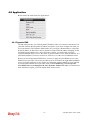
4.8 Application ................................................................................................................................ 266
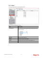
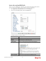
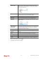
4.8.1 Dynamic DNS ......................................................................................................................266
4.8.2 GVRP
.............................................................................................................................272
4.8.3 IGMP Proxy .........................................................................................................................273
4.8.4 UPnP
.............................................................................................................................274
4.8.5 High Availability ...................................................................................................................276
4.8.6 Wake on LAN.......................................................................................................................287
4.8.7 SMS / Mail Alert Service ......................................................................................................288
4.9 VPN and Remote Access......................................................................................................... 292
4.9.1 VPN Client Wizard ...............................................................................................................292
4.9.2 VPN Server Wizard..............................................................................................................298
4.9.3 Remote Access Control .......................................................................................................303
4.9.4 PPP General Setup .............................................................................................................304
4.9.5 IPsec General Setup............................................................................................................307
4.9.6 VPN Profiles ........................................................................................................................308
4.9.7 VPN Trunk Management .....................................................................................................318
4.9.8 Connection Management ....................................................................................................323
4.10 Certificate Management ......................................................................................................... 325
vi
Vigor2960 Series User’s Guide
4.10.1 Local Certificate .................................................................................................................326
4.10.2 Trusted CA Certificate .......................................................................................................331
4.10.3 Remote Certificate .............................................................................................................333
4.11 SSL VPN................................................................................................................................. 335
4.11.1 SSL Web Proxy .................................................................................................................335
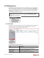
4.11.2 SSL Application .................................................................................................................337
4.11.3 Online User Status.............................................................................................................341
4.12 Central VPN Management ..................................................................................................... 342
4.12.1 General Setup....................................................................................................................343
4.12.2 CPE Management .............................................................................................................345
4.12.3 Log/Alert ............................................................................................................................354
4.13 Bandwidth Management ........................................................................................................ 355
4.13.1 Quality of Service...............................................................................................................355
4.13.2 QoS Rule ...........................................................................................................................359
4.13.3 Sessions Limit....................................................................................................................366
4.13.4 Bandwidth Limit .................................................................................................................369
4.14 USB Application...................................................................................................................... 373
4.14.1 Disk Status.........................................................................................................................373
4.14.2 FTP User Management .....................................................................................................374
4.14.3 Temperature Sensor..........................................................................................................375
4.14.4 Modem Support List...........................................................................................................377
4.15 System Maintenance.............................................................................................................. 378
4.15.1 TR-069 .............................................................................................................................378
4.15.2 Administrator Password.....................................................................................................380
4.15.3 Configuration Backup ........................................................................................................381
4.15.4 Syslog / Mail Alert ..............................................................................................................383
4.15.5 Time and Date ...................................................................................................................386
4.15.6 Access Control...................................................................................................................387
4.15.7 SNMP Setup ......................................................................................................................389
4.15.8 Reboot System ..................................................................................................................390
4.15.9 Firmware Upgrade .............................................................................................................392
4.16 Diagnostics............................................................................................................................. 393
4.16.1 Routing Table ....................................................................................................................393
4.16.2 ARP Cache Table ..............................................................................................................396
4.16.3 DHCP Table.......................................................................................................................399
4.16.4 Session Table ....................................................................................................................401
4.16.5 Traffic Graph......................................................................................................................402
4.16.6 Web Console .....................................................................................................................404
4.16.7 Ping/Trace Route...............................................................................................................404
4.16.8 Data Flow Monitor..............................................................................................................405
4.17 External Devices .................................................................................................................... 406
4.18 Product Registration............................................................................................................... 407
Chapter 5: Trouble Shooting.........................................................................................409
5.1 Checking If the Hardware Status Is OK or Not......................................................................... 409
5.2 Checking If the Network Connection Settings on Your Computer Is OK or Not ...................... 410
5.3 Pinging the Router from Your Computer .................................................................................. 413
5.4 Checking If the ISP Settings are OK or Not ............................................................................. 414
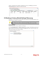
5.5 Backing to Factory Default Setting If Necessary...................................................................... 415
Vigor2960 Series User’s Guide
vii
5.6 Contacting DrayTek .................................................................................................................. 416
viii
Vigor2960 Series User’s Guide
Chapter 1: Introduction
The Vigor2960 Series integrates a rich suite of functions, including NAT, firewall, VPN,
load balance, and bandwidth management capability. These products are very suitable for
providing multi-integrated solutions to SME markets.
A Virtual Private Network (VPN) is an extension of a private network that encompasses
links across shared or public networks like an Intranet. A VPN enables you to send data
between two computers across a shared public Internet network in a manner that emulates
the properties of a point-to-point private link. The DrayTek Vigor2960 Series VPN router
supports Internet-industry standards technology to provide customers with open,
interoperable VPN solutions such as X.509, DHCP over Internet Protocol Security (IPsec)
up to 500 tunnels, and Point-to-Point Tunneling Protocol (PPTP).
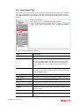
1.1 Web Configuration Buttons Explanation
Several main buttons appeared on the web pages are defined as the following:
Save and apply current settings.
Cancel current settings and recover to the previous saved settings, or
discard the settings configured in the page.
Go to next page.
Return to the previous page.
Complete the setting configuration.
Remove the setting if you are not satisfied with it.
Remove the selected entry.
Vigor2960 Series User’s Guide
1
Note: For the other buttons shown on the web pages, please refer to Chapter 4 for detailed
explanation.
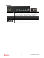
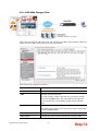
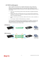
1.2 LED Indicators and Connectors
Before you use the Vigor router, please get acquainted with the LED indicators and connectors first.
The displays of LED indicators and connectors for the routers are different slightly.
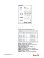
Description for LED
LED
ACT (Activity)
Status
Blinking
CSM
Off
On
VPN
On
Off
Blinking
On
Off
On
Off
Blinking
On
Off
The port is connected.
The port is disconnected.
The data is transmitting.
The port is connected with 1000Mbps.
The port is connected with 10/100Mbps.
The port is connected.
The port is disconnected.
The data is transmitting.
The port is connected with 1000Mbps.
The port is connected with 10/100Mbps.
On
Off
On
Blinking
On
Blinking
On
Off
On
DoS
WAN1/2
QoS
USB1/2
LED on Connector
Left LED
GigaWAN 1/2 (Green)
GigaLAN
1/2/3/4
Blinking
Explanation
The router is powered on and running
normally.
The router is powered off.
The profile(s) of CSM (Content Security
Management) for IM/P2P, URL/Web Content
Filter application can be enabled from
Firewall >>General Setup. (Such profile
must be established under CSM menu).
The VPN tunnel is active.
No VPN tunnel is active.
The DoS/DDoS function is active.
It will blink while deleting an attack.
The WAN1 or WAN2 connection is ready.
It will blink while transmitting data.
The QoS function is active.
The QoS function is disabled.
The USB device is connected and ready for
use.
The data is transmitting.
Right LED
(Green)
Left LED
(Green)
Right LED
(Green)
2
Vigor2960 Series User’s Guide
Vigor2960 Series User’s Guide
3
Connectors
Interface
Factory Reset
GigaWAN 1/2
GigaLAN 1/2/3/4
USB1/2
Description
Restore the default settings. Usage: Turn on the router (ACT LED is
blinking). Press the hole and keep for more than 5 seconds. When you
see the ACT LED begins to blink rapidly than usual, release the button.
Then the router will restart with the factory default configuration.
Connecters for remote networked devices.
Connecters for local networked devices.
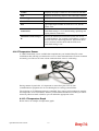
Connecter for Mobile HDD, 3G Modem or printer.
Connecter for a power cord.
ON/OFF - Power switch.
4
Vigor2960 Series User’s Guide
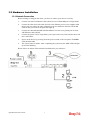
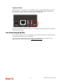
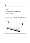
1.3 Hardware Installation
1.3.1 Network Connection
Before starting to configure the router, you have to connect your devices correctly.
1.
Connect one end of an Ethernet cable (RJ-45) to one of the LAN ports of Vigor2960s.
2.
Connect the other end of the cable (RJ-45) to the Ethernet port on your computer (that
device also can connect to other computers to form a small area network). The LAN
LED for that port on the front panel will light up.
3.
Connect the cable Modem/DSL Modem/Media Converter to any WAN port of router
with Ethernet cable (RJ-45).
4.
Connect the power cord to Vigor2960’s power port on the rear panel, and the other side
into a wall outlet.
5.
Power on the device by pressing down the power switch on the rear panel. The PWR
LED should be ON.
6.
The system starts to initiate. After completing the system test, the ACT LED will light
up and start blinking.
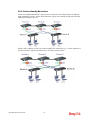
Below shows an outline of the hardware installation for your reference.
Vigor2960 Series User’s Guide
5
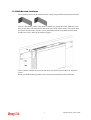
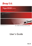
1.3.2 Wall-Mounted Installation
The Vigor2960 Series can be mounted on the wall by using standard brackets shown below.
Choose a flat surface (on the wall) which is suitable for placing the router. Make the screw
holes on the short side of the bracket aim at the screw holes on the router. Next, fasten both
the bracket and the router with two screws; and fasten both the wall and the bracket with
another two screws. Refer to the following figure.
Then, continue to fasten the screws on the other side of the router and the wall with other
screws.
When you finished about procedure, the router has been mounted on the wall firmly.
6
Vigor2960 Series User’s Guide
Chapter 2: Initial Configuration
For use the router properly, it is necessary for you to change the password of web
configuration for security and adjust primary basic settings.
This chapter explains how to setup a password for an administrator and how to adjust basic
settings for accessing Internet successfully. Be aware that only the administrator can change
the router configuration.
2.1 Changing Password
To change the password for this device, you have to access into the web browse with default
password first.
1.
Make sure your computer connects to the router correctly.
Notice: You may either simply set up your computer to get IP
dynamically from the router or set up the IP address of the computer to be
the same subnet as the default IP address of Vigor router 192.168.1.1.
For the detailed information, please refer to the later section - Trouble
Shooting of this guide.
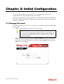
2.
Open a web browser on your PC and type http://192.168.1.1. A pop-up window will
open to ask for username and password. Please type default values on the window for
the first time accessing. The default value for user name is admin and the password is
admin. Next, click Login.
Vigor2960 Series User’s Guide
7
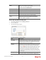
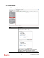
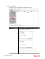
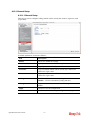
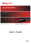
3.
Now, the Main Screen will pop up.
4.
Go to System Maintenance page and choose Administrator Password.
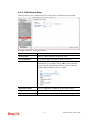
5.
Enter the login password (admin, in default) on the field of Original Password. Type a
new one in the field of New Password and retype it on the field of Confirm Password.
Then click Apply to continue.
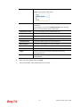
6.
Now, the password has been changed. Next time, use the new password to access the
Web Configurator for this router.
8
Vigor2960 Series User’s Guide
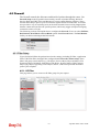
2.2 Quick Start Wizard
Quick Start Wizard is a wizard which is designed for configuring your router accessing
Internet with simply steps. In the Quick Start Wizard group, you can configure the router to
access the Internet with different modes such as Static, DHCP, PPPoE, or PPTP modes.
For most users, Internet access is the primary application. The router supports the Ethernet
WAN interface for Internet access.
Click Quick Start Wizard from the home page. Quick Start Wizard will guide the user to
establish LAN interface profile, WAN interface profile and select proper protocol for
connection. The following will explain in more detail for the various broadband access
configurations.
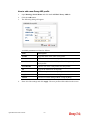
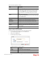
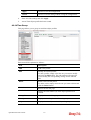
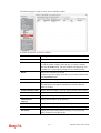
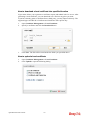
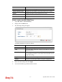
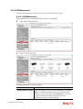
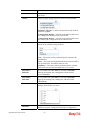
2.2.1 Step 1 – Specifying the WAN Profile
In the first page of Quick Start Wizard, please choose a WAN profile and specify IPv4
protocol.
Available parameters are listed as follows:
Item
Description
Profile
Use the drop down list to choose one of the WAN profiles
for modifying.
IPv4 Protocol
Use the drop down list to choose the type for the IPv4
protocol for such profile.
Vigor2960 Series User’s Guide
9
When you finish the above settings, please click Next to go to next page.
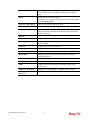
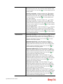
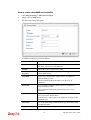
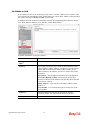
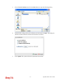
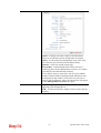
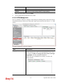
2.2.2 Step 2 - Configuring the Selected Protocol
This page will be changed according to the IPv4 Protocol Type selected on last page.
If Static is selected
If Static is selected, the following screen will appear. You can manually assign a static IP
address to the WAN interface and complete the configuration by applying the settings and
rebooting your router. Please type in values for Static IP address, Static Mask, Static
Gateway and Static DNS specified by your ISP, and then click Next.
Available parameters are listed as follows:
Item
Description
IP Address
Type a public IP address for such WAN profile.
Subnet Mask
Choose the static mask from the drop down list.
Gateway IP Address
Type a public gateway address for such WAN profile.
DNS Server IP
Address
Add – Click this button to display the IP address field for
adding a new IP address. Type the IP address on the tiny boxes
one by one.
10
Vigor2960 Series User’s Guide
Save – After finished the IP address configuration, click Save
to save the setting onto the router.
Previous
Click it to return to previous setting page.
Finish
Click it to finish the configuration.
Cancel
Click it to discard the settings configured in this page.
When you finished the above settings, please click Finish.
Vigor2960 Series User’s Guide
11
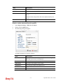
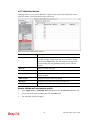
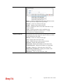
If DHCP is selected
DHCP allows a user to obtain an IP address automatically from a DHCP server on the
Internet. If you choose DHCP mode, the DHCP server of your ISP will assign a dynamic IP
address for Vigor2960 automatically. It is not necessary for you to assign any setting. (Host
Name is required for some ISPs).
Available parameters are listed as follows:
Item
Description
Host Name (Optional)
Type a name as the host name for identification.
Previous
Click it to return to previous setting page.
Finish
Click it to finish the configuration.
Cancel
Click it to discard the settings configured in this page.
When you finished the above settings, please click Finish.
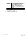
If PPPoE is selected
PPPoE stands for Point-to-Point Protocol over Ethernet. It relies on two widely accepted
standards: PPP and Ethernet. It connects users through an Ethernet to the Internet with a
common broadband medium, such as a single DSL line, wireless device or cable modem. All
the users over the Ethernet can share a common connection.
PPPoE is used for most of DSL modem users. All local users can share one PPPoE
connection for accessing the Internet. Your service provider will provide you information
about user name, password, and authentication mode.
If your ISP provides you the PPPoE (Point-to-Point Protocol over Ethernet) connection,
please select PPPoE for this router to get the following page. Enter the username and
password provided by your ISP on the web page.
12
Vigor2960 Series User’s Guide
Available parameters are listed as follows:
Item
Description
Username
Type in the username provided by ISP in this field.
Password
Type in the password provided by ISP in this field.
Previous
Click it to return to previous setting page.
Finish
Click it to finish the configuration.
Cancel
Click it to discard the settings configured in this page.
When you finished the above settings, please click Finish.
Vigor2960 Series User’s Guide
13
If PPTP is selected
This mode lets user get the IP group information by a DSL modem with PPTP service from
ISP. Your service provider will give you user name, password, and authentication mode for a
PPTP setting. Click PPTP as the protocol. Type in all the information that your ISP provides
for this protocol.
If your ISP offers you PPTP (Point-to-Point Tunneling Protocol) mode, please select PPTP
for this router. Next, enter the settings provided by your ISP on the web page.
Available parameters are listed as follows:
Item
Description
PPTP Over
Usually ISP dynamically assigns IP address to you each time
you connect to it and request. In some case, your ISP provides
service to always assign you the same IP address whenever you
request. In this case, you can fill in this IP address in the Fixed
IP field. Please contact your ISP before you want to use this
function.
Static – specify the IP address.
DHCP - obtain the IP address automatically.
14
Vigor2960 Series User’s Guide
Server Address
Type a remote IP address of PPTP server.
Username
Type in the username provided by ISP in this field.
Password
Type in the password provided by ISP in this field.
Previous
Click it to return to previous setting page.
IP Address
Type a public IP address for such WAN profile.
Subnet Mask
Choose the static mask from the drop down list.
Gateway IP Address
Type a public gateway address for such WAN profile.
DNS Server IP
Address
To add a new IP address, simply place the mouse cursor on this
filed. The following dialog will appear.
Add – Click this button to display the IP address field for
adding a new IP address.
Save – After finished the IP address configuration, click Save to
save the setting onto the router.
Previous
Click it to return to previous setting page.
Finish
Click it to finish the configuration.
Cancel
Click it to discard the settings configured in this page.
When you finished the above settings, please click Finish. Later, you can surf the Internet at
any time.
Vigor2960 Series User’s Guide
15
When the following screen appears, it means you have finished the Quick Start Wizard
configuration.
16
Vigor2960 Series User’s Guide
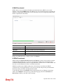
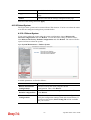
2.3 Register Vigor Router
Please follow the steps below to register the router.
1
Before using such function, please register your router online first. Log into the web
configurator of Vigor2960 and click Product Registration.
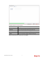
2
A Login page will be shown on the screen. Please type the account and password that
you created previously. And click Login.
Notice: If you haven’t an accessing account, please create a new one first. Please
read the articles on the Agreement regarding user rights carefully while
creating a user account.
Vigor2960 Series User’s Guide
17
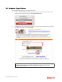
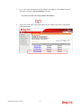
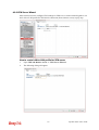
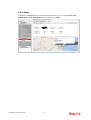
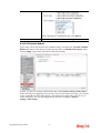
3
The following page will be displayed after you logging in MyVigor. From this page,
please click Add.
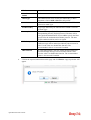
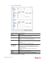
4
When the following page appears, please type in Nick Name (for the router) and choose
the right registration date from the popup calendar (it appears when you click on the
box of Registration Date). After adding the basic information for the router, please click
Submit.
18
Vigor2960 Series User’s Guide
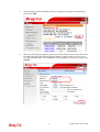
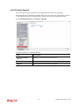
5
Now, your router information has been added to the database. Click OK to leave this
web page and return to My Information web page.
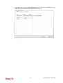
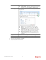
6
Take a look at the page of My Information, the new added Vigor2960 is listed under
Your Device List.
Vigor2960 Series User’s Guide
19
This page is left blank.
20
Vigor2960 Series User’s Guide
Chapter 3: Application and
Tutorial
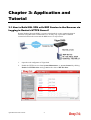
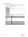
3.1 How to Build SSL VPN with RDP Service in the Browser via
Logging in Router's HTTPS Server?
Remote Desktop Protocol (RDP) is a protocol designed for secure communications in
networks using Microsoft Terminal Services. An easy way is provided to establish
connection between the router and the RDP Server via any browser.
1.
Open the web configurator of Vigor2960.
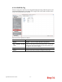
2.
Enable the HTTPS service from System Maintenance >> Access Control by clicking
Enable for HTTPS Allow and type 443 as the value of HTTPS Port.
Vigor2960 Series User’s Guide
21
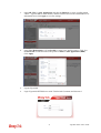
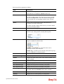
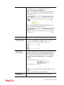
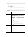
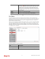
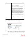
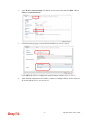
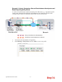
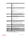
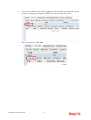
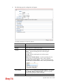
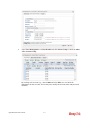
3.
Open SSL VPN >> SSL Application and click the RDP tab to create a profile named
“Win7”. Type IP address, Port number, and Screen Size based on the actual RDP server
information, then click Apply to save the settings.
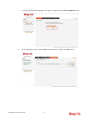
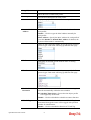
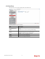
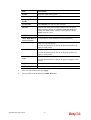
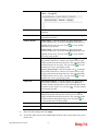
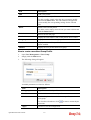
4.
Open User Management >> User Profile to create a new profile named “7788”. Set
the Password as 7788 and choose the profile of Win7 as SSL Application (RDP).
Click Apply.
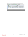
5.
Logout Vigor2960.
6.
Login Vigor2960 HTTPS Server with 7788 for both Username and Password.
22
Vigor2960 Series User’s Guide
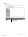
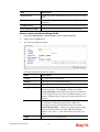
7.
A screen like the following figure will appear. Simply click the SSL Application link.
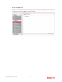
8.
In the following screen, click Connect for connecting to Win7, the RDP server.
Vigor2960 Series User’s Guide
23
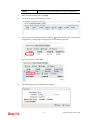
9.
After that, you can access into Windows 7 via a browser. Note the message below the
window. In which, TLS means Transport Layer Security.
24
Vigor2960 Series User’s Guide
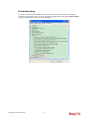
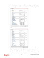
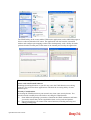
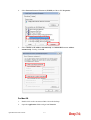
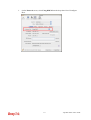
Troubleshooting
If you have installed Java Runtime Environment edition 6 but still cannot establish the
connection, please make sure you have disabled “Use TLS 1.0” in the Java Control Panel
as figure shown below. Then, try to connect again.
Vigor2960 Series User’s Guide
25
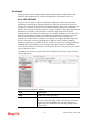
3.2 How to Configure OSPF?
OSPF (Open Shortest Path First) uses the algorithm of SPF (Shortest Path First) to calculate
the route metric. It is suitable for large network and complicated data exchange. Both
Vigor3900 and Vigor2960 support up to OSPF version 2(only for IPv4).
The autonomous system (AS) used in OSPF indicates the largest entity and can be divided
into several areas. Usually, Area 0 will be used as OSPF backbone which distributing the
routing information among areas.
When you need faster convergence than distance vector, want to support much larger
networks or want to have less susceptible to bad routing information, you can enable OSPF
feature to fit your request. Note that both routers must support OSPF function at the same
time to build the OSPF connection.
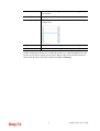
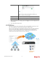
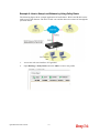
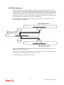
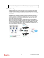
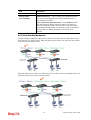
In the following example, a PC can go 192.168.2.0/24 and 192.168.4.0/24 without setting
any Static Route. Refer to the OSPF topology diagram listed below.
OSPF can place each router (e.g., Vigor3900A, Vigor3900B and Vigor2960 shown above) at
the root of a tree and calculate the shortest path to each destination according to the
cumulative cost to reach the destination.
Each router has its own view of the topology and calculates its own SPF tree, even though all
the routers build a shortest-path tree using the same link-state database.
26
Vigor2960 Series User’s Guide
Configuration for Vigor3900 A,
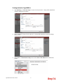
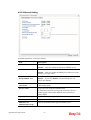
1. Open Routing >> General Setup to create a LAN (192.168.1.1/24) profile named lan1
with the settings shown below.
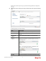
2. Next, continue to create a LAN (192.168.3.1/24) profile named lan2 with the settings
shown below.
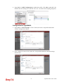
3. Open LAN >> Static Route Setup and click the Inter-LAN Route tab to enable this
profile.
Vigor2960 Series User’s Guide
27
4. Open LAN >> OSPF Configuration to enable this profile. Click Add to make the LAN
Profiles lan2 area setting as 11 and lan1 area as 11. (As shown in the topology diagram.)
Configuration for Vigor3900 B,
1. Open LAN >> General Setup to create a LAN (192.168.2.1/24) profile named lan1
with the settings shown below.
2. Next, continue to create a LAN (192.168.3.2/24) profile named lan2 with the settings
shown below.
28
Vigor2960 Series User’s Guide
3. Open LAN >> Static Route Setup and click the Inter-LAN Route tab to enable this
profile.
4. Open LAN >> OSPF Configuration to enable this profile. Click Add to make the LAN
Profiles lan2 area setting as 11 and lan1 area as 11. (As shown in the topology diagram.)
Configuration for Vigor2960,
1. Open LAN >> General Setup to create a LAN (192.168.4.1/24) profile named lan1
with the settings shown below.
Vigor2960 Series User’s Guide
29
2. Next, continue to create a LAN (192.168.3.3/24) profile named lan2 with the settings
shown below.
3. Open LAN >> General Setup and click the Inter-LAN Route tab to enable this profile.
30
Vigor2960 Series User’s Guide
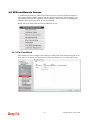
4. Open Routing >> OSPF Configuration to enable this profile. Click Add to make the
LAN Profiles lan2 area setting as 11 and lan1 area as 11. (As shown in the topology
diagram.)
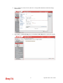
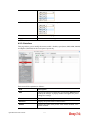
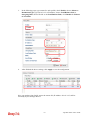
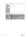
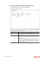
5. After setting, check the routing information (marked with red line) which is created by
OSPF.
Routing information for Vigor3900 A
Routing information for Vigor3900 B
Routing information for Vigor2960
Vigor2960 Series User’s Guide
31
32
Vigor2960 Series User’s Guide
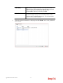
3.3 How to Configure LAN to LAN IPsec Tunnel between
Vigor2960 and Other Router
Here provides an example about LAN to LAN IPsec tunnel established between Vigor2960
and Vigor2710.
Configuring Vigor2960
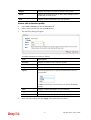
1.
Access into the web configurator of Vigor2960 and open VPN and Remote Access >>
VPN Profiles to add a new VPN configuration.
Type the Pre-shared key and choose a WAN Profile. Specify Local IP/Subnet Mask
with 192.168.29.0/24. The Remote Host should be Vigor 2710's WAN IP address; And
the Remote IP/Subnet Mask should be192.168.2.0/24.
2.
Click Apply to save the settings and return to previous page.
Vigor2960 Series User’s Guide
33
Configuring Vigor2710
1.
2.
In Vigor2710, it is necessary to build two VPN connections (for two WANs) to connect
with Vigor2960. Please open the web configurator of Vigor2710 and open VPN and
Remote Access >> LAN to LAN.
First, please type the name of such VPN connection in the field of Profile Name
(e.g., 2960).
Check the box of Enable this profile.
Choose Dial-Out as Call Direction and check the box of Always on.
For Dial-Out Settings, please choose IPsec Tunnel and type WAN IP address of
Vigor2960 in the field of Server IP/Host Name for VPN (e.g., 1.169.162.1). Type the
same IKE Pre-Shared Key configured in Vigor2960.
34
Vigor2960 Series User’s Guide
3.
For the role of Vigor2710 is dialing-out, please skip Dial-In setting. Type the Remote
Network IP and Remote Network Mask of Vigor2960 to complete configuration.
4.
Please check if the VPN connection is built successfully in both devices respectively.
For Vigor2960, open VPN and Remote Access>>IPsec>>Status for viewing the
result.
As to Vigor2710, please open VPN and Remote Access>>Connection Management
to confirm the result.
Vigor2960 Series User’s Guide
35
3.4 CVM Application - How to manage the CPE (router) through
Vigor2960?
To manage CPEs through Vigor2960, you have to set URL on CPE first and set username
and password for Vigor2960. For this section, we use Vigor2830 series as the example. The
firmware upgrade for the CPE can be done through Vigor2830 series.
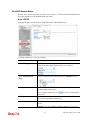
3.4.1 Configure Settings on Vigor2960
1.
Access into the web user interface of Vigor2960.
2.
Open System Maintenance>>Access Control. Check Enable for Web Allow and
type the value for Web Port. Then click Apply to save the settings.
3.
Open Central VPN Management>>CPE Management. On the page of CPE
Maintenance, there is no CPE managed by Vigor2960.
4.
Open Central VPN Management>>General Setup.
36
Vigor2960 Series User’s Guide
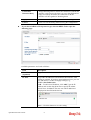
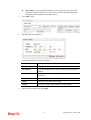
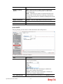
5.
Click the General Setup tab. Check the Enable box. Specify the WAN interface from
the WAN Profile drop down list. Type the values for Port, Username, and Password
respectively. Remember the values configured in this page.
6.
Click Apply to save the settings.
3.4.2 Configure Settings on CPE
To manage CPEs through Vigor2960, you have to set ACS URL on CPE first and set
username and password for Vigor2960.
1.
Connect one CPE (e.g., Vigor2830 series) and get ready to access into the web user
interface of the CPE.
2.
Open a web browser (for example, IE, Mozilla Firefox or Netscape) on your computer
and type http://192.168.1.1.
3.
Please type username and password on the window. If you don’t know the correct
username and password, please consult our dealer to get them.
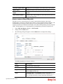
4.
Open System Maintenance >> TR-069.
5.
In the field of ACS Server, type the URL (IP address with port number) of Vigor2960:
“http://{IP address of Vigor296}:{CVM port}/ACSServer/services/ACSServlet”
and type the same Username and Password defined on the page of Central VPN
Management>>General Setup in Vigor2960. Then, click Enable for CPE Client and
then click OK to save the settings.
Vigor2960 Series User’s Guide
37
3.4.3 Invoke Remote Management for CPE
1.
Login the web user interface of the CPE.
2.
Open System Maintenance>>Management Setup.
3.
Check Allow management from the Internet to set management access control.
38
Vigor2960 Series User’s Guide
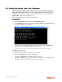
3.4.4 Enable WAN Connection on CPE
1.
Login the web user interface of the CPE.
2.
Open WAN>>Internet Access. Use the drop down list of Access Mode on WAN1 to
select MPoA (RFC1483/2684). Then, click Details Page.
3.
Click Specify an IP address. Type correct WAN IP address, subnet mask and gateway
IP address for your CPE. Then click OK.
Note: Reboot the CPE device and re-log into Vigor2960. CPE which has registered
to Vigor2960 will be captured and displayed on the page of Central VPN
Management>>CPE Management.
Vigor2960 Series User’s Guide
39
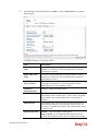
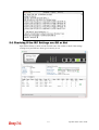
3.4.5 Check CPE Maintenance Page
1.
Return to the web user interface of Vigor2960.
2.
Open Central VPN Management>>CPE Management.
3.
Now there is one CPE managed (Vigor2830) by Vigor2960 on the page of CPE
Maintenance.
40
Vigor2960 Series User’s Guide
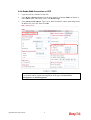
3.5 CVM Application - How to build the VPN between remote
devices and Vigor2960?
When a remote device is managed by Vigor2960 series, it is easy to build VPN between
these two devices.
1.
Access into the web user interface of Vigor2960 series.
2.
Open Central VPN Management>>CPE Management. The icons displayed on the
screen means the remote devices are ready for building VPN with Vigor2960.
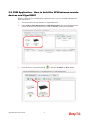
3.
Click the device icon (marked with
Vigor2960 Series User’s Guide
41
) and click the PPTP or IPsec button.
Or click Advanced to open the following page for specified the CPE you want. Click
Connect after finished the settings.
4.
A confirmation dialog will appear. Click OK and wait for a moment.
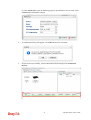
5.
If VPN is built successfully, related information will be displayed on Connected
Devices.
42
Vigor2960 Series User’s Guide
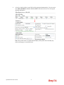
6.
A LAN to LAN profile for such VPN will be generated automatically. You can access
into VPN and Remote Access>>LAN to LAN of the remote device for viewing the
detailed information.
Note: The profile name is created automatically by the system. Do not modify any
value in such page to avoid VPN error.
Vigor2960 Series User’s Guide
43
3.6 CVM Application - How to upgrade CPE firmware through
Vigor2960?
3.6.1 Import firmware file from your PC to Vigor2960
1.
Suppose the newest firmware file is located on your PC. You can upload it from your
PC to Vigor2960.
2.
Log into the web user interface of Vigor2960.
3.
Open System Maintenance>>Access Control. Check Enable for Web Allow and
type the value for Web Port. Then click Apply to save the settings.
4.
Open Central VPN Management>>CPE Management. Click CPE Maintenance. In
the Maintenance area, click File Explorer.
5.
In the File Explorer dialog, click Upload.
44
Vigor2960 Series User’s Guide
6.
In the Upload dialog, click the Browse.. button to find out the firmware (e.g.,
2830_0508 in this case) you want to upload from PC to Vigor2960. Then, click
Upload.
Vigor2960 Series User’s Guide
45
7.
When the file is uploaded successfully, later you will find the one in the File Explorer
dialog.
46
Vigor2960 Series User’s Guide
3.6.2 Set a new firmware upgrade profile
To create a new firmware upgrade profile, one CPE (e.g., 2830 in this case) must be
managed by Vigor2960 at least. Otherwise, the profile cannot be created successfully.
1.
Open Central VPN Management>>CPE Management. Click CPE Maintenance. In
the Maintenance area, click Add.
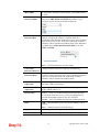
2.
In the following dialog, type the name for the new profile; specify the vigor router the
file will be applied to; choose Firmware Upgrade as the Action, choose Now as the
Schedule (it means the firmware upgrade will be performed after clicking Apply); and
type the string of the firmware filename or click
Vigor2960 Series User’s Guide
47
to choose a correct one.
3.
When you finished the above settings, click Apply to save them. The new maintenance
profile has been created and displayed on the Maintenance area.
4.
Now, the new firmware will be loaded into the CPE immediately (based on the
schedule setting – now).
Note that a red icon,
will appear during the period of firmware upgrading.
And, in the web user interface of client’s CPE, the system will show you that firmware
upgrade is on going.
48
Vigor2960 Series User’s Guide
5.
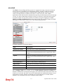
Please wait for a moment. Later, open Central VPN Management>>Log/Alert>>Log
page to check the result. If [Finished] is displayed, it means the firmware upgrade of
specified CPE has completed.
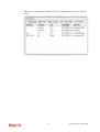
3.6.3 Check the Device Information
1.
Open Central VPN Management>>CPE Management. In the Managed Devices
Status area, choose the router (representing Vigor2830) and click Detail.
2.
Check the software version field.
Vigor2960 Series User’s Guide
49
3.7 How to use High Availability for Vigor routers?
The High Availability (HA) feature in Vigor2960 can ensure the business continuity for your
organization. IT staff can use HA as a simple solution for the disaster recovery. Vigor2960
utilizes the Common Address Redundancy Protocol (CARP) to avoid the system crashing
which could stop the normal operation and then cause considerable lost of the entire
organization.
When the HA feature is enabled, the network administrator can set another Vigor2960(s) as
the backup device(s) to deliver full routing services during the shutdown of the main
Vigor2960. The network administrator can use a Virtual IP (e.g. 192.168.1.100) for both
master device and backup device. During the system uptime, the master device (e.g.
192.168.1.1) can offer services and act as the Virtual IP. Once the master device is
temporarily out-of-service, the backup device(s) (e.g. 192.168.1.5) will take over the service
that the Virtual IP does and deliver all routing functions.
Note: Make sure the WAN interfaces for both Router A and Router B are well
connected. Both routers can be used to access into Internet.
Note: For advanced applications, please refer to FAQ/Application Notes on
www.draytek.com.
50
Vigor2960 Series User’s Guide
For router A
1. Access into the web user interface of Vigor2960.
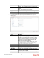
2. Open Applications >>High Availability.
3. In the tab of High Availability Global Setup, choose Hot-Standby as Redundant
Method; choose Primary as Config Synchronization Rule; type draytek as
Authentication Key; choose Immediate as Advance Preemption Mode. Click Apply to
save the settings.
4. Click the High Availability Profile Setup tab to create HA profile(s). Click Add.
Vigor2960 Series User’s Guide
51
5. Create an HA profile. Refer to the following figures.
6. Now, the configuration for router A has been finished.
For router B
1. Access into the web user interface of Vigor2960.
2. Open Applications >>High Availability.
3. In the tab of High Availability Global Setup, choose Hot-Standby as Redundant
Method; choose Secondary as Config Synchronization Rule; type the lan1 IP address
configured in router A; type draytek as Authentication Key; choose Automatic as
Advance Preemption Mode. Click Apply to save the settings.
52
Vigor2960 Series User’s Guide
Type the lan1
IP address
configured in
Router A
4. Click the High Availability Profile Setup tab to create HA profile(s). Click Add.
5. Create an HA profile. Refer to the following figures.
Vigor2960 Series User’s Guide
53
6. Now, the configuration for router B has been finished.
After finished the above settings, it is the time to activate HA function for both router A and
router B. It is recommended to activate the HA for router A (Primary) before router B
(Secondary).
Simply open Applications>>High Availability and click the High Availability
Global Setup. Locate Enable High Availability. Check the box and click Apply to
save the settings.
Under such construction, when Router A (defined as Master device) is powered off, Router
B (defined as Slave device) will be up and take over all the jobs that Router A performs.
Later, when Router A is powered on again, all the jobs will return to Router
54
Vigor2960 Series User’s Guide
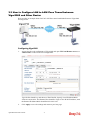
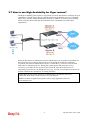
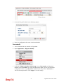
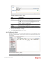
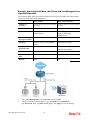
3.8 How to Configure DNS Inbound Load Balance on Vigor
2960?
Vigor2960 can offer the mapped IP address to respond the DNS query coming from the
remote end through the designate domain to reduce the loading of the network traffic.
WAN1 IP Address: 1.1.1.1
WAN2 IP Address: 2.2.2.2
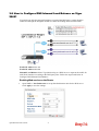
Inbound Load Balance allows Vigor2960 acting as a DNS Server to separate the traffic for
each WAN interface according to the DNS query time. Follow the steps listed below to
Configure DNS Inbound Load Balance.
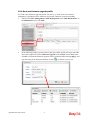
Enabling Web service on the Router
1.
Open NAT >> Port Redirection to set up Port Redirection rules for the Web server.
Click Apply to save the settings.
Vigor2960 Series User’s Guide
55
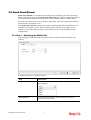
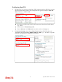
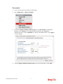
2.
Open WAN >> Load Balance and click the tab of Inbound Load Balance to enable the
service. Click Add.
3.
Add a profile named “yourdomain.com”. Define WAN1 weights 1 and WAN2 weights 2.
It means the total DNS query time will be three, one will pass through WAN1; two will
pass through WAN2.
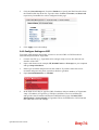
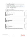
4.
Click the Detail tab and locate Additional A Record. Type “www” as the name of the
Host, and type “192.168.1.10” as the IP Address.
56
Vigor2960 Series User’s Guide
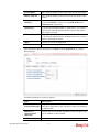
5.
Then click Apply to save the settings.
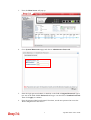
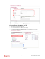
Now, make a test for inbound load balance.
Click Start>> Run and type cmd. Execute the command, nslookup, for DNS query test.
First DNS query
>www.yourdomain.com
Server: [google-public-dns-a.google.com]
Address: 8.8.8.8
Name: www. yourdomain.com
Address: 1.1.1.1
Second DNS query
> www.yourdomain.com
Server: [google-public-dns-a.google.com]
Address: 8.8.8.8
Name: www.yourdomain.com
Address: 2.2.2.2
Third DNS query
> www.yourdomain.com
Server: [google-public-dns-a.google.com]
Address: 8.8.8.8
Name: www.yourdomain.com
Address: 2.2.2.2
Note: It is recommended to clear cache before executing “nslookup” for DNS query.
Vigor2960 Series User’s Guide
57
This page is left blank.
58
Vigor2960 Series User’s Guide
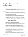
Chapter 4: Advanced
Configuration
After finished basic configuration of the router, you can access Internet with ease. For the
people who want to adjust more setting for suiting his/her request, please refer to this chapter
for getting detailed information about the advanced configuration of this router. As for other
examples of application, please refer to chapter 3.
4.1 WAN
Quick Start Wizard offers user an easy method to quick setup the connection mode for the
router. Moreover, if you want to adjust more settings for different WAN modes, please go to
WAN group and click the General Setup link.
Basics of Internet Protocol (IP) Network
IP means Internet Protocol. Every device in an IP-based Network including routers, print
server, and host PCs, needs an IP address to identify its location on the network. To avoid
address conflicts, IP addresses are publicly registered with the Network Information Centre
(NIC). Having a unique IP address is mandatory for those devices participated in the public
network but not in the private TCP/IP local area networks (LANs), such as host PCs under
the management of a router since they do not need to be accessed by the public. Hence, the
NIC has reserved certain addresses that will never be registered publicly. These are known as
private IP addresses, and are listed in the following ranges:
From 10.0.0.0 to 10.255.255.255
From 172.16.0.0 to 172.31.255.255
From 192.168.0.0 to 192.168.255.255
What are Public IP Address and Private IP Address
As the router plays a role to manage and further protect its LAN, it interconnects groups of
host PCs. Each of them has a private IP address assigned by the built-in DHCP server of the
Vigor router. The router itself will also use the default private IP address: 192.168.1.1 to
communicate with the local hosts. Meanwhile, Vigor router will communicate with other
network devices through a public IP address. When the data flow passing through, the
Network Address Translation (NAT) function of the router will dedicate to translate
public/private addresses, and the packets will be delivered to the correct host PC in the local
area network. Thus, all the host PCs can share a common Internet connection.
Get Your Public IP Address from ISP
In ADSL deployment, the PPP (Point to Point)-style authentication and authorization is
required for bridging customer premises equipment (CPE). Point to Point Protocol over
Ethernet (PPPoE) connects a network of hosts via an access device to a remote access
concentrator or aggregation concentrator. This implementation provides users with
significant ease of use. Meanwhile it provides access control, billing, and type of service
according to user requirement.
When a router begins to connect to your ISP, a serial of discovery process will occur to ask
for a connection. Then a session will be created. Your user ID and password is authenticated
Vigor2960 Series User’s Guide
59
via PAP or CHAP with RADIUS authentication system. And your IP address, DNS server,
and other related information will usually be assigned by your ISP.
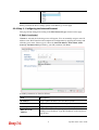
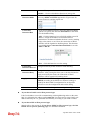
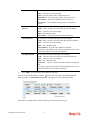
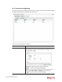
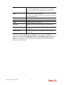
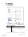
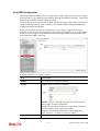
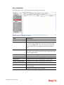
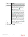
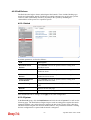
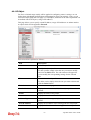
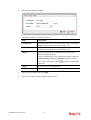
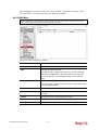
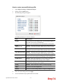
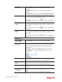
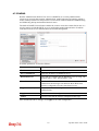
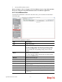
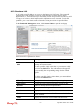
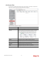
4.1.1 General Setup
This section will introduce some general settings of Internet and explain the connection
modes for WAN profiles in details.
This router supports multi-WAN function. It allows users to access Internet and combine the
bandwidth of the WAN profiles to speed up the transmission through the network. Each
WAN port can connect to different ISPs, even if the ISPs use different technology to provide
telecommunication service (such as DSL, Cable modem, etc.). If any connection problem
occurred on one of the ISP connections, all the traffic will be guided and switched to the
normal communication port for proper operation.
Note: Some menu items (e.g., Bridge VLAN) are available only under Advance Mode.
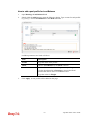
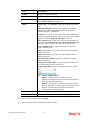
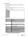
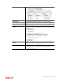
Web Page in Basic Mode
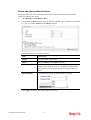
Web Page in Advance Mode
60
Vigor2960 Series User’s Guide
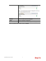
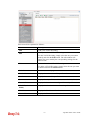
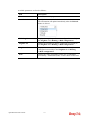
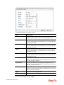
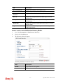
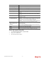
Each item will be explained as follows:
Item
Description
Add
Add a new WAN profile.
Such function is available in Advance mode only.
Edit
Modify the selected WAN profile.
To edit a profile, simply select the one you want to modify
and click the Edit button. The edit window will appear for
you to modify the corresponding settings for the selected
rule.
Delete
Remove the selected WAN profile. Such function is
available in Advance mode only.
To delete a profile, simply select the one you want to delete
and click the Delete button.
Refresh
Renew current web page.
Mode
Specify the mode for adding /editing (Advance) new WAN
profile or just editing (Basic) existing WAN profile.
Switch Mode
This mode determines a WAN interface can be set with
single or double VLAN ID values.
Normal – It means only one VLAN ID value can be
configured for the WAN interface.
Double Tag – It means two VLAN ID values (802.1q in q)
can be configured for a WAN interface.
Profile Number Limit
Display the total number (50) of the profiles to be created.
Profile (max length:7)
Display the profile name.
Enable
Display the status of the profile. False means disabled; True
means enabled.
Description
Display a brief explanation for such profile.
Port
Display the physical WAN interface for such profile.
IPv4 Protocol Type
Display the IPv4 protocol selected by the profile.
IPv6 Protocol Type
Display the IPv6 protocol selected by the profile.
VLAN Tag
If the data transmitted with tag, Enable will be displayed in
this field. Otherwise, Disable will be shown instead.
VLAN ID
Display the VLAN ID of the profile.
Priority
Display the level of the priority for such profile.
Vigor2960 Series User’s Guide
61
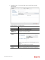
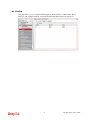
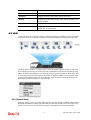
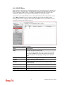
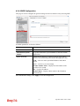
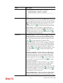
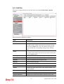
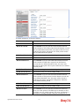
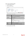
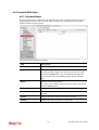
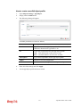
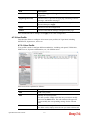
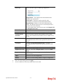
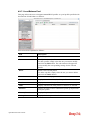
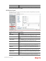
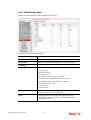
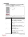
4.1.1.1 Ethernet WAN Profiles
How to add a new WAN profile:
1.
If the router is under Basic mode, you have to switch into Advance mode. If the router
is under Advance mode, go to Step 4 directly.
2.
A confirmation dialog will appear. Click OK to apply the related settings for Advance
mode.
3.
Re-login the system.
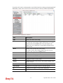
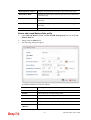
4.
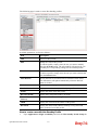
Open WAN>>General Setup. Click the Add button to open the following dialog.
Different protocol type selected will bring up different configuration web page.
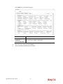
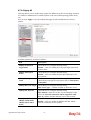
Available parameters for global configuration are listed as follows:
Item
Description
Profile (max
Type a name (less than 7 characters) for such profile.
62
Vigor2960 Series User’s Guide
length:7)
Enable
Check this box to enable such profile.
Description
Give the brief description for such profile.
Port
Display the physical WAN interface for such profile.
Default MAC
Address
Enable – Click it to enable the default MAC address for
such profile.
Disable – Click it to type the MAC address manually for
such profile.
MAC Address - Specify the MAC address for such profile if
you click Disable for Default MAC address. In default, the
system will determine it automatically.
IPv4 Protocol
There are four connection modes for you to specify for IPv4
protocol type. Each mode will bring up different web page.
Mode
Determine such profile will be used for NAT or routing.
IPv6 Protocol
There are five connection modes for you to specify for IPv6
protocol type. Each mode will bring up different web page.
Enable Schedule
Reconnect
Enable – Click it to enable the function of reconnecting the
network automatically within the time schedule.
Schedule Time Object - Choose the time object profile
to be applied by such WAN.
Disable – Click it to disable the schedule reconnect function.
VLAN Tag
Vigor2960 Series User’s Guide
Enable – Click it to enable the function of VLAN Tag. Data
transmitted through the router will be tagged with specified
number for identification.
Disable – Click it to disable the function of VLAN Tag.
63
Data transmitted through the router will not be tagged with
any number.
VLAN ID
Type the VLAN ID number for such profile.
Priority(802.1p)
Type the packet priority number for such VLAN. The range
is from 0 to 7.
Apply
Click it to save the configuration and exit the dialog.
Cancel
Click it to exit the dialog without saving the configuration.
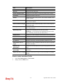
Global configuration allows you to enable the profile, give a brief explanation for such
profile, specify the VLAN ID, specify MAC address, choose IPv4 and IPv6 protocol,
and specify the mode of the data transmission (NAT or Routing).
64
Vigor2960 Series User’s Guide
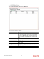
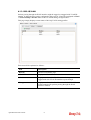
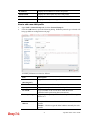
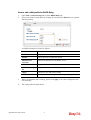
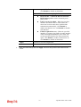
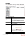
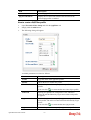
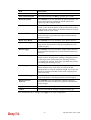
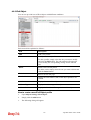
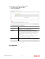
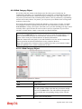
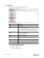
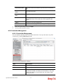
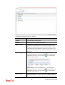
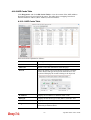
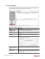
Different IPv4 and IPv6 protocol types specified will bring up different configuration
web page.
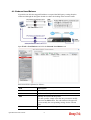
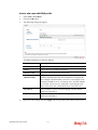
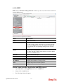
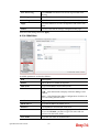
If you choose Static as IPv4 protocol type, click the Static tab to open the following
page:
Available parameters are listed as follows:
Item
Description
IP Address
Type the IP address specified for such profile.
Subnet Mask
Use the drop down list to choose the subnet mask for such
profile.
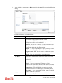
Gateway IP
Address
Type a public gateway address for such WAN profile.
DNS Server IP
Address
Add – Click this button to display the IP address field for
adding a new IP address. Type the IP address on the tiny
boxes one by one.
Save – After finished the IP address configuration, click
Save to save the setting onto the router.
IP Alias
Vigor2960 Series User’s Guide
Type other IP addresses to be bound to this interface. This
65
setting is optional. If you have typed addresses here, you can
see and choose it in later web page settings (e.g.,
NAT>>Port Redirection/DMZ Host).
Add – Click this button to display the IP address field for
adding a new IP address. Type the IP address on the tiny
boxes one by one.
Save – After finished the IP address configuration, click
Save to save the setting onto the router.
MTU/MRU
Type the value of MTU/MRU. The default value is 1500.
Connection
Detection Mode
Select a detecting mode for this WAN interface. There are
three ways ARP, PING and HTTP supported in Vigor
router for you to choose to send the request out.
Connection
Detection Host
Assign an IP address or Domain name as a destination to be
detected whether the host is active (sending reply to the
router) or not. If not, the connection of WAN interface will
be regarded as breaking down. This function is available
when Connection Detection Mode is set with PING or
HTTP.
Add – click this button to have a field for adding a new IP
address.
Save – click this button to save the setting.
Connection
Detection Interval
Assign an interval period of time for each detecting.
66
Vigor2960 Series User’s Guide
Connection
Detection Retry
Assign detecting times to ensure the connection of the WAN
interface. After passing the times you set in this field and no
reply received by the router, the connection of WAN
interface will be regarded as breaking down.
Apply
Click it to save the configuration and exit the dialog.
Cancel
Click it to exit the dialog without saving the configuration.
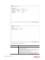
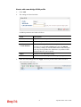
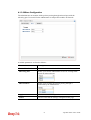
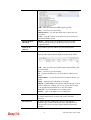
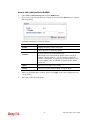
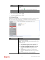
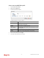
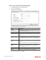
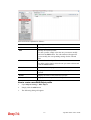
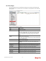
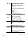
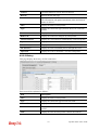
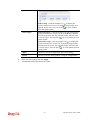
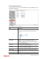
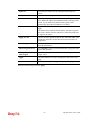
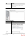
If you choose DHCP as IPv4 protocol type, click the DHCP Tab to open the
following page:
Available parameters are listed as follows:
Item
Description
Host Name
(Optional)
Type a name as the host name for identification.
IP Alias
Type other IP addresses to be bound to this interface. This
setting is optional. If you have typed addresses here, you can
see and choose it in later web page settings (e.g.,
NAT>>Port Redirection.
Add – To add a new IP address, click Add. Type the IP
address and use the drop down list to specify the subnet
mask. Next, click Save. The new one will be added and
displayed on the field under the box.
Save – Click this button to save the setting.
Vigor2960 Series User’s Guide
67
MTU/MRU
It means Max Transmit Unit for packet. The default setting
is 1500.
Connection
Detection Mode
Select a detecting mode for this WAN interface. There are
three ways ARP, PING and HTTP supported in Vigor
router for you to choose to send the request out.
Connection
Detection Host
Add – click this button to have a field for adding a new IP
address. Assign an IP address or Domain name as a
destination to be detected whether the host is active (sending
reply to the router) or not. If not, the connection of WAN
interface will be regarded as breaking down. This function is
available when Connection Detection Mode is set with
PING or HTTP.
Save – Click this button to save the setting.
Connection
Detection Interval
Assign an interval period of time for each detecting.
Connection
Detection Retry
Assign detecting times to ensure the connection of the WAN
interface. After passing the times you set in this field and no
reply received by the router, the connection of WAN
interface will be regarded as breaking down.
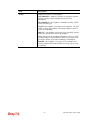
Vendor Class ID
(option 60)
Type a string for identification of vendor. It is required for
the mode, DHCP (option 60).
DHCP Client ID
(option 61)
Type a string for identification of client. It is required for the
mode, DHCP (option 61).
Specify DNS
Enable – Click it to enable the function of DNS specified.
It is used for local service (e.g., NTP, ping diagnostic) or
used for forwarding packets to PC on LAN/VPN.
Disable – Click it to disable the function of DNS specified.
DNS
Add – click this button to have a field for adding a new IP
address.
Save – click this button to save the setting.
Apply
Click it to save the configuration and exit the dialog.
Cancel
Click it to exit the dialog without saving the configuration.
68
Vigor2960 Series User’s Guide
If you choose PPPoE as IPv4 protocol type, click the PPPoE Tab to open the
following page:
Available parameters are listed as follows:
Item
Description
Username
Type the user name offered by your ISP.
Password
Type the password offered by your ISP.
MTU/MRU
Type the value of MTU/MRU. The default value is 1492.
Service Name
This is an optional setting. Some ISP will offer such
information and ask you to type the same data on this field.
Debug
Click Enable to display the PPPoE debug message in
Syslog. The default setting is Disable.
Always On
Enable – Click it to enable the function of Always On. The
router will keep network connection all the time.
Disable – Click it to disable the function of Always On.
Fixed IP
Enable – Click it to enable the function of Always On. The
router will keep network connection all the time.
Disable – Click it to disable the function of Always On.
Fixed IP Address – Type an IP address here if you choose
Enable for Fixed IP.
Connection
Detection Mode
Select a detecting mode for this WAN interface. There are
two ways PING and HTTP supported in Vigor router for
you to choose to send the request out.
Vigor2960 Series User’s Guide
69
Connection
Detection Host
If you choose PING/HTTP as Connection Detection Mode,
you have to specify the detection host address in this field.
Use the default setting.
Add – Click this button to have a field for adding a new IP
address. Assign an IP address or Domain name as a
destination to be detected whether the host is active (sending
reply to the router) or not. If not, the connection of WAN
interface will be regarded as breaking down. This function
is available when Connection Detection Mode is set with
PING or HTTP.
Save – Click this button to save the setting.
Connection
Detection Interval
Assign an interval period of time for each detecting.
Connection
Detection Retry
Assign detecting times to ensure the connection of the WAN
interface. After passing the times you set in this field and no
reply received by the router, the connection of WAN
interface will be regarded as breaking down.
IP Alias
Type other IP addresses to be bound to this interface. This
setting is optional. If you have typed addresses here, you can
see and choose it in later web page settings (e.g.,
NAT>>Port Redirection/DMZ Host).
Add – Click this button to display the IP address field for
adding a new IP address. Type the IP address on the tiny
boxes one by one.
Save – After finished the IP address configuration, click
Save to save the setting onto the router.
Specify DNS
Enable – Click it to enable the function of DNS specified.
It is used for local service (e.g., NTP, ping diagnostic) or
70
Vigor2960 Series User’s Guide
used for forwarding packets to PC on LAN/VPN.
Disable – Click it to disable the function of DNS specified.
DNS
Add – click this button to have a field for adding a new IP
address.
Save – click this button to save the setting.
Apply
Click it to save the configuration and exit the dialog.
Cancel
Click it to exit the dialog without saving the configuration.
If you choose PPTP as IPv4 protocol type, click the PPTP Tab to open the
following page:
Available parameters are listed as follows:
Item
Description
PPTP Over
Usually ISP dynamically assigns IP address to you each time
you connect to it and request. In some case, your ISP
provides service to always assign you the same IP address
whenever you request. In this case, you can fill in this IP
address in the Fixed IP field. Please contact your ISP
before you want to use this function.
Choose a proper protocol, Static or DHCP. After finished
the settings in such page, you need to open the Static or
DHCP tab for configuring the settings there.
Server Address
Type the IP address of PPTP server offered by your ISP.
Username
Type the user name offered by your ISP.
Password
Type the password offered by your ISP.
MTU/MRU
Type the value of MTU/MRU. The default value is 1452.
Debug
Click Enable to display the PPTP debug message in syslog.
The default setting is Disable.
Always On
Enable – Click it to enable the function of Always On. The
Vigor2960 Series User’s Guide
71
router will keep network connection all the time.
Disable – Click it to disable the function of Always On.
Connection
Detection Mode
Select a detecting mode for this WAN interface. There are
two ways PING and HTTP supported in Vigor router for
you to choose to send the request out.
Connection
Detection Host
If you choose PING/HTTP as Connection Detection Mode,
you have to specify the detection host address in this field.
Use the default setting.
Add – Click this button to have a field for adding a new IP
address. Assign an IP address or Domain name as a
destination to be detected whether the host is active (sending
reply to the router) or not. If not, the connection of WAN
interface will be regarded as breaking down. This function
is available when Connection Detection Mode is set with
PING or HTTP.
Save – Click this button to save the setting.
Connection
Detection Interval
Assign an interval period of time for each detecting.
Connection
Detection Retry
Assign detecting times to ensure the connection of the WAN
interface. After passing the times you set in this field and no
reply received by the router, the connection of WAN
interface will be regarded as breaking down.
Apply
After finished the PPTP configuration, please click Static or
DHCP (according to the PPTP Over Protocol setting) to
modify the Static/DHCP configuration for such profile.
Click it to save the configuration and exit the dialog.
Cancel
Click it to exit the dialog without saving the configuration.
If you choose Link-Local as IPv6 protocol type
Link-Local address is used for communicating with neighbouring nodes on the same
link. It is defined by the address prefix fe80::/64. You don't need to setup Link-Local
address manually for it is generated automatically according to your MAC Address.
If you choose PPP as IPv6 protocol type
Simply refer to the section of “If you choose PPPoE as IPv4 protocol type, click the
PPPoE Tab to open the following page” for detailed information.
72
Vigor2960 Series User’s Guide
If you choose Static as IPv6 protocol type, click the StaticV6 tab to open the
following page:
Available parameters are listed as follows:
Item
Description
IPv6 Address
Type the IP address for such protocol.
IPv6 Prefix Length
Type your IPv6 address prefix length.
IPv6 Gateway
Address
Type your IPv6 gateway address.
IPv6 DNS Server
Address
Type your IPv6 primary DNS Server address.
Add – Click this button to have a field for adding a new IP
address.
Save – Click this button to save the setting.
Apply
Click it to save the configuration and exit the dialog.
Cancel
Click it to exit the dialog without saving the configuration.
Vigor2960 Series User’s Guide
73
If you choose DHCP IA NA as IPv6 protocol type, click the DHCPV6 Tab to open
the following page:
Available parameters are listed as follows:
Item
Description
DHCP (IA_NA)
Gateway Address
Type the gateway IP address for IPv6 DHCP IA_NA mode.
DHCP (IA_NA)
DNS Address
Add – Click this button to type primary DNS server address
for IPv6.
Save – Click this button to save the setting.
Apply
Click it to save the configuration and exit the dialog.
Cancel
Click it to exit the dialog without saving the configuration.
If you choose DHCP IA PD as IPv6 protocol type
It is not necessary for you to configure any web page.
5.
After finished the settings configuration, click Apply to save and apply the settings.
74
Vigor2960 Series User’s Guide
4.1.1.2 USB WAN Profiles
Open WAN>>General Setup and click the USB WAN tab.
Each item will be explained as follows:
Item
Description
Edit
Modify the selected USB WAN profile.
To edit a profile, simply select the one you want to modify
and click the Edit button. The edit window will appear for
you to modify the corresponding settings for the selected
rule.
Refresh
Renew current web page.
Profile
Display the profile name.
Enable
Display the status of the profile. False means disabled; True
means enabled.
Description
Display a brief explanation for such profile.
Port
Display the physical WAN interface for such profile.
Protocol
Display the protocol selected by the profile.
Vigor2960 Series User’s Guide
75
How to edit a USB WAN profile
1.
Choose one of the USB WAN profiles and click Edit.
2.
The settings under Global tab are listed as below:
Available parameters are listed as follows:
3.
Item
Description
Profile
Display the name of the USB WAN profile.
Enable
Check it to enable the USB WAN profile.
Description
Give the brief description for such profile.
Port
Display the physical WAN interface for such profile.
Protocol
Choose the connection mode for USB WAN.
Default
Click it to restore the default settings.
Apply
Click it to save and exit the dialog.
Cancel
Click it to exit the dialog without saving anything.
After finished the settings above, click the 3G/4G PPP or 4G DHCP tab (based on the
Protocol specified) to display the following page:
76
Vigor2960 Series User’s Guide
Or,
Available parameters are listed as follows:
Item
Description
3G/4G PPP
SIM PIN code -Type PIN code of the SIM card that will be
used to access Internet.
Modem Initial String 1-Such value is used to initialize USB
modem. Please use the default value. If you have any
question, please contact to your ISP.
Modem Initial String 2-The initial string 1 is shared with
APN. In some cases, user may need another initial AT
Vigor2960 Series User’s Guide
77
command to restrict 3G band or do any special settings.
APN -APN means Access Point Name which is provided
and required by some ISPs. Type the name.
Modem Dial String -Such value is used to dial through USB
mode. Please use the default value. If you have any question,
please contact to your ISP.
PPP Username -Type the PPP username (optional).
PPP Password -Type the PPP password (optional).
4G DHCP
SIM Pin code –Type PIN code of the SIM card that will be
used to access Internet.
Network Mode – Force Vigor router to connect Internet
with the mode specified here. If you choose 4G/3G/2G as
network mode, the router will choose a suitable one
according to the actual wireless signal automatically.
APN Name – APN means Access Point Name which is
provided and required by some ISPs.
4.
Default
Click it to restore the default settings.
Apply
Click it to save and exit the dialog.
Cancel
Click it to exit the dialog without saving anything.
Enter all of the settings and click Apply.
78
Vigor2960 Series User’s Guide
4.1.1.3 Bridge VLAN Profiles
Open WAN>>General Setup and click the Bridge VLAN tab.
It can specify a VLAN ID for WAN port and offers more advanced environmental
application for the users through the bridge technique in WAN port and LAN port.
Each item will be explained as follows:
Item
Description
Add
Click to create a new profile.
Edit
Modify the selected USB WAN profile.
To edit a profile, simply select the one you want to modify
and click the Edit button. The edit window will appear for
you to modify the corresponding settings for the selected
rule.
Delete
Remove the selected WAN profile. Such function is
available in Advance mode only.
To delete a profile, simply select the one you want to delete
and click the Delete button.
Refresh
Renew current web page.
Profile Number Limit
Display the total number of the profiles to be created.
Profile
Display the profile name.
WAN Profile
Display the WAN profile selected.
LAN VLAN/Member
Display VLAN ID number of the LAN port selected.
Vigor2960 Series User’s Guide
79
How to add a new bridge VLAN profile
1.
Click Add.
2.
The settings are listed as below:
Available parameters are listed as follows:
3.
Item
Description
Profile
Type the name of the profile.
WAN Profile
Use the drop down list to choose the WAN interface.
LAN
VLAN/Member
Choose a VLAN profile from the drop down list.
You have to open LAN>>Switch page and click 802.1Q
VLAN for creating VLAN ID number bound with LAN port
(802.1Q VLAN profile) first. Otherwise, no profiles will be
displayed here for you to specify.
Apply
Click it to save and exit the dialog.
Cancel
Click it to exit the dialog without saving anything.
Enter all of the settings and click Apply. The new profile will be shown as below.
80
Vigor2960 Series User’s Guide
4.1.2 Inbound Load Balance
Vigor2960 can offer the mapped IP address to respond the DNS query coming from the
remote end through the designate domain to reduce the loading of the network traffic.
Open WAN>>Load Balance and click the Inbound Load Balance tab.
Each item will be explained as follows:
Item
Description
Enable
Check the box the enable inbound load balance function.
Add
Add a new WAN profile for inbound load balance.
Edit
Modify the selected WAN profile.
To edit a profile, simply select the one you want to modify
and click the Edit button. The edit window will appear for
you to modify the corresponding settings for the selected
rule.
Delete
Remove the selected WAN profile.
Vigor2960 Series User’s Guide
81
To delete a profile, simply select the one you want to delete
and click the Delete button.
Refresh
Renew current web page.
Profile Number Limit
Display the total number of the profiles to be created.
Enable
Display the status of the profile. False means disabled; True
means enabled.
Domain Name
Display the domain name used by the profile.
Mode
Display the mode (failover or load balance) applied by the
profile.
IP Mapping
Display the WAN interfaces used by the profile.
Weight
Display the weight(s) that WAN interface(s) used.
Alias Interface
Display the WAN interfaces used by the IP alias.
IP
Display the alias IP settings used by the profile.
Alias Weight
Display the weight that the above IP address used.
How to create a new Inbound Load Balance profile
Such page allows you to create a new WAN profile for inbound load balance.
1.
Open WAN>>Inbound Load Balance.
2.
Simply click the Add button to open the following dialog.
Available parameters are listed as follows:
Item
Description
Status
Check this box to enable such profile.
Domain Name
Type an available domain name to serve the inbound load
balance.
82
Vigor2960 Series User’s Guide
Mode
Specify the type (Load Balance or Failover) of the WAN
profile for inbound load balance
Priority Setting
It is available only when Failover is selected as the Mode.
There are five levels (Top, 2, 3, 4 and 5) which can be
specified for WAN profiles (including default WAN profiles
and user-defined WAN profiles).
Interface
Mapping/Weight
The domain name will inform the remote end with the IP
address for DNS query asked by the remote end.
The incoming query from the WAN interfaces specified in IP
Mapping will be processed according to the weight value.
Add – Click it to choose a WAN interface and weight.
Save – Click it to save the settings.
IP Mapping – Use the drop down list to choose a WAN
interface profile which will be used by the domain.
Weight – Use the drop down list to choose the one you want.
Alias Setting
The purpose of such setting is to specify a WAN IP address
from the WAN interface or by typing it manually to respond
DNS query.
Add – Click it to add a new IP address.
Save – Click it to save the settings.
Alias From WAN Interface – The alias IP setting can be
specified from existed WAN IP alias.
Alias From Manual Input – The alias IP setting can be
specified manually. The Alias Interface is not necessary for
such method.
Alias Interface –Use the drop down list to choose a WAN
interface profile for the alias IP setting.
Alias – Use the drop down list to choose an alias IP setting
(for Alias From WAN Interface) or type an IP address
manually (for Alias From Manual Input).
Weight –Use the drop down list to choose the one you want.
Vigor2960 Series User’s Guide
83
3.
After finished the settings on the Basic page, click the Detail Tab to open the following
dialog.
Available parameters are listed as follows:
Item
Description
DNS Parameter
To configure Vigor router as a DNS server, type the related
information for applying the function of DNS.
TTL – It means Time to live of a DNS response. Available
setting range is from 0 to 2147483647.
Refresh – Set the time for the PC in LAN to refresh the data.
Retry – Set the times of retry if the PC fails to contact with
Vigor router before the refreshing expired.
Expire – PC stops responding to the query from Vigor router
when such time setting has expired.
Negative Cache TTL – Set the negative caching time (name
error).
Email – Type the e-mail address of the administrator.
NS Record
This page is used to specify name server which will be used
as DNS server.
Add – Click it to add a new server with specified name and
IP address.
Save – Click it to save the settings.
HOST – Type the domain name of the server. This is
optional. If no information added here, the router will use the
DNS server configured in Domain Name under the Basic tab.
Name Server –Type the URL for the name server which
will be used to receive the DNS query forwarded by HOST.
IP Address – This is optional. If required, simply type the IP
address of the NS record server.
MX Record
This is used to specify the mail server with IP address.
Add –Click it to add a new server with specified name and IP
84
Vigor2960 Series User’s Guide
address.
Save – Click it to save the settings.
Host –Type the name (URL) of the mail server.
Mail Server – Type the name (URL) of the mail server.
IP Address – Type the IP address of the mail server.
Preference – Set a number for the priority of such mail
server.
4.
Additional A
Record
It is used to record the DNS query by IPv4 address.
Add –Click it to add a new host with specified IP address.
Save – Click it to save the settings.
Host –Set a domain name.
IP Address – Type the IP address of the mail server.
AAAA Record
It is used to record the DNS query by IPv6 address.
Add –Click it to add a new host with specified IPv6 address.
Save – Click it to save the settings.
Host – Set a domain name.
IPv6 Address –Type the IPv6 address of the host.
Any query concerning of Host will be forwarded to the server
selected in Reference for advanced process.
CNAME Record
It is used to record the DNS query for CNAME.
Add – Click it to add a new host with specified reference.
Save – Click it to save the settings.
Host – Set a domain name.
Reference – Choose a sub domain name from the drop down
list.
Any query concerning of Host will be forwarded to the server
selected in Reference for advanced process.
Click Apply. A new profile will be added on the page.
on the left side of the selected inbound load
You can create sub-domain by clicking
balance profile. A sub-domain setting page will appear for you to add new profile.
Note that the configuration is similar to the way stated on the above steps.
Vigor2960 Series User’s Guide
85
4.1.3 Switch
This page allows you to configure Mirroring Port, Mirrored Port, enable/disable WAN
interface, and configure 802.1Q VLAN ID for different WAN interfaces, and so on.
86
Vigor2960 Series User’s Guide
4.1.3.1 802.1Q VLAN
Packets passing through the WAN interface might be tagged or untagged with VLAN ID
number. It depends on the setting configured in this page for VLAN ID configured in WAN
>>General Setup>>Profile relates to the VLAN ID setting configured here.
This page simply displays current status of 802.1Q VALN setting profiles.
Each item will be explained as follows:
Item
Description
Refresh
Click it to reload this page.
VLAN ID
Display the VLAN ID number.
Member
Display number of the WAN interface for the packets
tagged with such VLAN ID number to pass through.
Untag
Display number of the WAN interface for the VLAN ID
will be untagged for packets passing through the WAN
interface selected.
Vigor2960 Series User’s Guide
87
4.1.3.2 Mirror Configuration
The administrator can monitor all the packets passing through mirrored port with the
mirroring port. It is useful for the administrator to analyze the troubles on Network.
Available parameters are listed as follows:
Item
Description
Enable This Profile
Check the box to enable the Mirror function for the switch.
Mirroring Port
Select a port for the administrator to use for viewing traffic
sent from mirrored ports.
Mirrored Port
Select a port to make the packets passing through it
monitored by the administrator.
Apply
Click it to save the configuration.
Cancel
Click it to discard the settings configured in this page.
88
Vigor2960 Series User’s Guide
4.1.3.3 Interface Configuration
This page allows you to modify the status (enable / disable), speed(Auto,10M,100M,1000M)
and duplex (Half/Full) for the WAN ports respectively.
Each item will be explained as follows:
Item
Description
Edit
Choose the interface listed below and click the Edit button
to modify the settings. A pop up window will appear for you
to change the settings.
Interface – Display the name of WAN interface.
Enable – Check it to enable such interface.
Speed – Use the drop down list to specify the transmission
rate (Auto, 10M, 100M or 1000M) for such interface.
Apply – Click it to save and exit the dialog.
Vigor2960 Series User’s Guide
89
Cancel – Click it to exit the dialog without saving anything.
Refresh
Renew current web page.
Interface
Display the name of the WAN port on the router.
Enable
Display the status of the profile. False means disabled; True
means enabled.
Duplex
Display the duplex used (full or half) by such profile.
Speed
Display the transmission rate (10M, 100M, 1000M or Auto)
of the date for such profile.
4.2 LAN
Local Area Network (LAN) is a group of subnets regulated and ruled by router. The design
of network structure is related to what type of public IP addresses coming from your ISP.
The most generic function of Vigor router is NAT. It creates a private subnet of your own.
As mentioned previously, the router will talk to other public hosts on the Internet by using
public IP address and talking to local hosts by using its private IP address. What NAT does
is to translate the packets from private IP address to public IP address to forward the right
packets to the right host and vice versa. Besides, Vigor router has a built-in DHCP server
that assigns private IP address to each local host.
4.2.1 General Setup
This page allows you to set LAN profiles for PCs in LAN. Settings of DHCP, DHCP Relay,
RADVD and DHCPv6 settings are generated automatically by the system when the LAN
profile is created. You can edit these settings by switching into each tab individually.
90
Vigor2960 Series User’s Guide
Note: One LAN profile shall be enabled at least to keep the normal operation. The default
LAN profile named “lan1” shall not be deleted. Otherwise, the system might be damaged. If
such file is deleted due to careless, please reset your router to restore the default setting.
4.2.1.1 General Setup
This page allows you to enable the profile, give a brief explanation for such profile, specify
the VLAN ID, specify MAC address, and choose protocol type for such profile.
Each item will be explained as follows:
Item
Description
Add
Add a new LAN profile.
Edit
Modify the selected LAN profile.
To edit a profile, simply select the one you want to modify
and click the Edit button. The edit window will appear for
you to modify the corresponding settings for the selected
rule.
Delete
Remove the selected LAN profile.
To delete a rule, simply select the one you want to delete and
click the Delete button.
Refresh
Renew current web page
Profile Number Limit
Display the total number of the profiles to be created.
Profile (max length:7)
Display the name of the LAN profile.
Enable
Display the status of the profile. False means disabled; True
means enabled.
Description
Display the brief explanation for the LAN profile.
VLAN ID
Display the VLAN ID configured for the LAN profile.
IPv4 Protocol
Display the IPv4 protocol type for the LAN profile.
Vigor2960 Series User’s Guide
91
IP Address
Display the IP address for such LAN profile.
Subnet Mask
Display the subnet mask for such LAN profile.
DHCP Server
Display the status (Enable/Disable) of the DHCP server.
IPv6 Protocol
Display the IPv6 protocol type for the LAN profile.
How to add a new LAN profile
1.
Open LAN>>General Setup and click the General Setup tab.
2.
Click the Add button to open the following dialog. Different protocol type selected will
bring up different configuration web page.
Available parameters are listed as follows:
Item
Description
Profile
(max length:7)
Type the name of the LAN profile.
Enable
Check this box to enable such profile.
Description
Type the description for the new LAN profile.
VLAN ID
Type a number as the VLAN ID to make the data be
identified while performing data transmission.
Priority(802.1p)
Type the packet priority number for such profile. The range is
from 0 to 7.
Default MAC
Address
Enable – Click it to enable the default MAC address for such
profile.
Disable – Click it to type the MAC address manually for such
profile.
92
Vigor2960 Series User’s Guide
MAC Address
If Default MAC address is disabled, please specify a MAC
address manually.
IPv4 Protocol
Display the fixed type (static) for the IPv4 protocol for such
profile.
Mode
Choose NAT or ROUTING as the operation mode for such
profile.
IP Address
Type the IP address of the router for the LAN profile.
Subnet Mask
Use the drop down list to choose a suitable mask for the LAN
profile.
DHCP Server
Enable – Click it to enable the DHCP server. The DHCP
server will assign the IP address randomly for the LAN user.
The range of the IP addresses must be defined in DHCP Start
IP and DHCP End IP.
Disable – Click it to disable the DHCP server.
DHCP Start IP
Type an IP address as the starting point for DHCP server.
DHCP End IP
Type an IP address as the ending point for DHCO server.
DHCP DNS
Set the private IP address for DNS server. If this field is
blank, users on LAN will treat Vigor2960 as the DNS server.
Add – Click it to add a new IP address for DNS server.
Save – Click it to save the setting.
DHCP IP Lease
Time
Set a lease time for the DHCP server. The time unit is minute.
DHCP Routers
In general, this box will be blank. It means Vigor2960 will be
regarded as the gateway for the user.
However, if you want to use other gateway, please assign the
IP address in this field.
DHCP Next Server
Type the IP address of the secondary DHCP server.
DHCP Options
DHCP packets can be processed by adding option number
and data information when such function is enabled.
Each DHCP option is composed by an option number with
data. For example,
Option number:100
Data: abcd
When such function is enabled, the specified values for
DHCP option will be seen in DHCP reply packets.
Vigor2960 Series User’s Guide
93
Add – Click it to add a new DHCP option profile.
Save – Click it to save the setting.
DHCP Option – Use the drop down list to choose the one
you want.
Value – Type the content of the data to be processed by the
function of DHCP option.
Specify Remote
Dial-in IP
Enable – Check the box to enable this function. Remote
clients within the range specified below can access into
Vigor2960 WUI.
Gateway IP
Address
Type a public gateway address for such WAN profile.
More Subnet
Different subnets can be created under one LAN profile.
Specify other subnets which might be needed in the future.
Add – Click it to add a new subnet mask with IP address and
specified mode.
Save – Click it to save the settings.
IP – Type the IP address if you click Add for adding a new
entry.
Subnet Mask – Use the drop down list to choose the one you
want.
Mode – Specify NAT or Routing as the mode.
DHCP – Click Enable to activate the DHCP function on such
subnet. When it is enabled, you have to specify the IP range
to be assigned by the DHCP server for such subnet.
Start IP – Type an IP address as a starting point.
End IP – Type an IP address as an ending point.
DNS Redirection
Enable – It can redirect DNS queries from such LAN profile
to router's DNS Server. It must work with LAN DNS
function.
IPv6 Protocol
It defines the IPv6 connection types for LAN interface.
Possible types contain Link-Local, Static and DHCP-SLA.
Except Link-Local, each type requires different parameter
settings.
94
Vigor2960 Series User’s Guide
Link-Local- Link-Local address is used for communicating
with neighbouring nodes on the same link. It is defined by the
address prefix fe80::/10. You don't need to setup Link-Local
address manually for it is generated automatically according
to your MAC Address.
Static –This type allows you to setup static IPv6 address for
LAN.
DHCP-SLA- DHCPv6 client mode would use IA_NA option
of DHCPv6 protocol to obtain IPv6 address from server.
3.
IPv6 Address
If Static is chosen as IPv6 Protocol, please type the IPv6
address in this field.
IPv6 Prefix Length
Display the IPv6 prefix length.
DHCPv6 SLA
WAN Interface
If DHCP-SLA is chosen as IPv6 Protocol, please choose one
of the WAN profiles in this field.
DHCPv6 SLA ID
The ID number set here is used by an individual organization
to create its own local addressing hierarchy and to identify
subnets.
Apply
Click it to save and exit the dialog.
Cancel
Click it to exit the dialog without saving anything.
When you finish the above settings, please click Apply to save the configuration and
exit the dialog.
Vigor2960 Series User’s Guide
95
4.2.1.2 DHCP Relay
DHCP stands for Dynamic Host Configuration Protocol. The router by factory default acts a
DHCP server for your network so it automatically dispatch related IP settings to any local
user configured as a DHCP client. It is highly recommended that you leave the router
enabled as a DHCP server if you do not have a DHCP server for your network.
If you want to use another DHCP server in the network other than the Vigor Router’s, you
can let Relay Agent help you to redirect the DHCP request to the specified location.
This page allows users to specify which subnet that DHCP server is located that the relay
agent should redirect the DHCP request to.
Each item will be explained as follows:
Item
Description
Edit
Modify the selected LAN profile.
To edit a profile, simply select the one you want to modify
and click the Edit button. The edit window will appear for
you to modify the corresponding settings for the selected
rule.
Refresh
Renew current web page.
Profile
Display the name of the LAN profile.
Enable
Display the status of the profile. False means disabled; True
means enabled.
DHCP Server Location
Display the LAN or WAN profile for the DHCP server.
DHCP Server IP
Display the IP address of DHCP server.
DHCP Relay Agent IP
Display the IP address of DHCP relay agent server.
96
Vigor2960 Series User’s Guide
How to edit a LAN profile for DHCP Relay
1.
Open LAN>>General Setup and click the DHCP Relay tab.
2.
Choose one of the LAN profiles by clicking on it and click the Edit button to open the
following dialog.
Available parameters are listed as follows:
Item
Description
Profile
Display the name of the LAN profile.
Enable
Check this box to enable this profile.
DHCP Server
Location
Choose the interface for the DHCP server.
DHCP Server IP
Type the IP address of DHCP Server.
DHCP Relay Agent
IP
Type the IP address of DHCP Relay Agent.
Apply
Click it to save and exit the dialog.
Cancel
Click it to exit the dialog without saving anything.
3.
When you finish the above settings, please click Apply to save the configuration and
exit the dialog.
4.
The LAN profile has been edited.
Vigor2960 Series User’s Guide
97
4.2.1.3 Inter-LAN Route
To make the users in different LAN communicating with each other, please check the box to
enable Inter-LAN route function.
98
Vigor2960 Series User’s Guide
4.2.1.4 RADVD
The router advertisement daemon (radvd) sends Router Advertisement messages, specified
by RFC 2461, to a local Ethernet LAN periodically and when requested by a node sending a
Router Solicitation message. These messages are required for IPv6 stateless
auto-configuration.
Each item will be explained as follows:
Item
Description
Edit
Modify the selected LAN profile.
To edit a profile, simply select the one you want to modify
and click the Edit button. The edit window will appear for
you to modify the corresponding settings for the selected
rule.
Refresh
Renew current web page.
Profile
Display the name of the LAN profile.
Enable
Display the status of the profile. False means disabled; True
means enabled.
Advertisement Lifetime
Display the lifetime value.
The lifetime associated with the default router in units of
minutes, ranging from 10 ~ 150. It is used to control the
lifetime of the prefix. A lifetime of 0 indicates that the router
is not a default router and should not appear on the default
router list.
Vigor2960 Series User’s Guide
99
How to edit a LAN profile for RADVD
1.
Open LAN>>General Setup and click the RADVD tab.
2.
Choose one of the LAN profiles by clicking on it and click the Edit button to open the
following dialog.
Available parameters are listed as follows:
Item
Description
Profile
Display the name of the LAN profile.
Enable
Check this box to enable this profile.
Advertisement
Lifetime
Type a value for advertisement lifetime.
The lifetime associated with the default router in units of
minutes, ranging from 10 ~ 150. It is used to control the
lifetime of the prefix. A lifetime of 0 indicates that the router
is not a default router and should not appear on the default
router list.
Apply
Click it to save and exit the dialog.
Cancel
Click it to exit the dialog without saving anything.
3.
When you finish the above settings, please click Apply to save the configuration and
exit the dialog.
4.
The LAN profile has been edited.
100
Vigor2960 Series User’s Guide
4.2.1.5 DHCP6
DHCP6 Server could assign IPv6 address to PC according to the Start/End IPv6 address
configuration.
Each item will be explained as follows:
Item
Description
Edit
Modify the selected LAN profile.
To edit a profile, simply select the one you want to modify
and click the Edit button. The edit window will appear for
you to modify the corresponding settings for the selected
rule.
Refresh
Renew current web page.
Profile
Display the name of the LAN profile.
Enable
Display the status of the profile. False means disabled; True
means enabled.
Mode
Display the mode (automatic setting or manual setting)
specified for such profile.
Start IP
Display the starting IP address of the IP address pool for
DHCP server.
End IP
Display the ending IP address of the IP address pool for
DHCP server.
DNS
Display the private IP address for DNS server.
How to edit a LAN profile for DHCPv6
1.
Open LAN>>General Setup and click the DHCPv6 tab.
2.
Choose one of the LAN profiles by clicking on it and click the Edit button to open the
following dialog.
Vigor2960 Series User’s Guide
101
Available parameters are listed as follows:
Item
Description
Profile
Display the name of the LAN profile.
Enable
Check this box to enable this profile.
Mode
Choose Automatic Setting or Manual Setting.
Automatic Setting – It is not necessary to configure Start
IP, End IP and DNS setting. The system will assign suitable
address automatically.
Manual Setting – You should type the Start IP address and
End IP address manually.
Start IP
Set the starting IP address of the IP address pool for DHCP
server. The format the IP address shall be similar to the
following example:
2000:0000:0000:0000:0000:0000:0000:10 or 2000::10.
End IP
Set the ending IP address of the IP address pool for DHCP
server. The format the IP address shall be similar to the
following example:
2000:0000:0000:0000:0000:0000:0000:10 or 2000::10.
DNS
It is available when Manual Setting is selected as Mode.
Set the private IP address for DNS server. If this field is
blank, users on LAN will treat Vigor2960 as the DNS server.
102
Vigor2960 Series User’s Guide
Add – Click it to add a new IP address for DNS server.
Save – Click it to save the setting.
Apply
Click it to save and exit the dialog.
Cancel
Click it to exit the dialog without saving anything.
3.
When you finish the above settings, please click Apply to save the configuration and
exit the dialog.
4.
The LAN profile has been edited.
4.2.2 PPPoE Server
This feature makes the router working like an ISP, providing PPPoE connections to LAN
PCs. The only difference is that local PCs don't need an ADSL modem.
There are several advantages of using PPPoE connections on the LAN. Firstly, the PPPoE
server can secure the LAN PC connections with username/password authentication.
Secondly, it can prevent ARP attack by nature. Thirdly, the system administrator can
configure quota (time/traffic based) for each user as ISP does.
Vigor2960 Series User’s Guide
103
4.2.2.1 Online Client Status
This page displays general information for PPPoE server; allows you to disconnect the
network connection to PPPoE server.
Each item will be explained as follows:
Item
Description
Disconnect
Click it to disconnect the profile connection.
Auto Refresh
Specify the interval of refresh time to obtain the latest status.
The information will update immediately when the Refresh
button is clicked.
Refresh
Renew current web page.
MAC Address
Display the MAC address of the client’s host.
User Name
Display the user name used to access into the PPPoE server.
IP Address
Display the IP address of the client’s host.
Up Time
Display the time that the PPPoE connection built.
RX Bytes
Display the total amount of received packets.
TX Bytes
Display the total amount of transmitted packets.
104
Vigor2960 Series User’s Guide
4.2.2.2 General Setting
Available parameters are listed as follows:
Item
Description
PPPoE Server
Disable – Click it to disable this function.
Enable – Click it to enable the function of PPPoE server.
PPPoE User Isolation
Disable – Click it to disable this function.
Enable – Click it to isolate the PPPoE users who access into
Internet via Vigor router.
Deny Internet Access
Except PPPoE User
Disable –Click it to disable this function.
Enable – If you click Enable, only the PPPoE user can
access into Internet.
Access Concentrator
(AC) Name
Type the name which will be reported as the access
concentrator name.
Service Name
Type a specific string for authentication.
It causes the named service to be advertised in a Service
Name tagged in the PADO (PPPoE Active Discovery
Offer) frame.
Primary DNS
Type an IP address as primary DNS.
Secondary DNS
Type another IP address as secondary DNS.
PPPoE Server
Authentication Type
Choose the authentication type for PPPoE server.
Vigor2960 Series User’s Guide
105
Any PPPoE user shall pass the authentication of PPPoE
server and access into Internet.
User Authentication
Type
Users in LAN can access into Internet through Vigor router
with RADIUS, LDAP or local authentication. Specify the
type for the users.
LDAP profiles
It is available when LDAP is selected as User
Authentication Type.
If you choose LDAP as the authentication type, use the drop
down list to specify the LDAP profile.
DHCP From
It is available when RADIUS is selected as User
Authentication Type.
DHCP Relay
Enable - If you want to use another DHCP server in the
network other than the Vigor Router’s, you can let Relay
Agent help you to redirect the DHCP request to the specified
location.
DHCP Server Location – Choose one of the interfaces for
DHCP server.
DHCP Server IP Address - Set the IP address of the DHCP
server you are going to use so DHCP Relay can help to
forward the DHCP request to the DHCP server.
Apply
Click it to save and exit the dialog.
Cancel
Click it to discard current page modification.
106
Vigor2960 Series User’s Guide
4.2.2.3 History
This page displays records of connection status (up or down) and the connection time and the
name of the user who accesses into PPPoE server of such router.
Each item will be explained as follows:
Item
Description
User Name
Display the user name used to access into the PPPoE server.
Action
Display the connection status (up or down) of the user
account.
Time
Display the connection time.
If the action is “Down”, such field will display the total
connection time.
If the action is “up”, such field will display the time point
that the user account access into the PPPoE server.
Vigor2960 Series User’s Guide
107
4.2.3 Switch
This page allows you to configure Mirroring Port, Mirrored Port, enable/disable LAN
interface, and configure 802.1Q VLAN ID for different LAN interfaces, and so on.
4.2.3.1 802.1Q VLAN
Virtual LANs (VLANs) are logical, independent workgroups within a network. These
workgroups communicate as if they had a physical connection to the network. However,
VLANs are not limited by the hardware constraints that physically connect traditional LAN
segments to a network. As a result, VLANs allow the network manager to segment the
network with a logical, hierarchical structure. VLANs can define a network by application or
department. For instance, in the enterprise, a company might create one VLAN for
multimedia users and another for e-mail users; or a company might have one VLAN for its
Engineering Department, another for its Marketing Department, and another for its guest
who can only use Internet not Intranet. VLANs can also be set up according to the
organization structure within a company. For example, the company president might have
his own VLAN, his executive staff might have a different VLAN, and the remaining
employees might have yet a different VLAN. VLANs can also set up according to different
company in the same building to save the money and reduce the device establishment.
User can select some ports to add into a VLAN group. In one VLAN group, the port number
can be single one or more.
The purpose of VLAN is to isolate traffic between different users and it can provide better
security application.
Each item will be explained as follows:
Item
Description
Add
Add a new VLAN ID setting.
Edit
Modify the selected VLAN ID setting.
To edit VALN ID setting, simply select the one you want to
modify and click the Edit button. The edit window will
appear for you to modify the corresponding settings for the
selected rule.
108
Vigor2960 Series User’s Guide
Delete
Remove the selected VLAN ID setting.
To delete a VLAN ID setting, simply select the one you want
to delete and click the Delete button.
Refresh
Renew current web page.
Profile Number Limit
Display the total number of the profiles to be created.
VLAN ID
Display the VLAN ID number.
Member
Display the LAN interface that is used to access into Internet
for such LAN profile with the VLAN ID number.
Untag
Display the LAN interface that packets transmitted to
Internet through such LAN profile with the VLAN ID
number is tagged or untagged.
How to add a new 802.1Q VLAN profile
1.
Open LAN>>Switch and click the 802.1Q VLAN tab.
2.
Click the Add button.
3.
The following dialog will appear.
Available parameters are listed as follows:
Item
Description
VLAN ID
Type the number as the VLAN ID. Type a number used for
identification on VLAN for your computer. Later, you have
to type the same ID number for each PC which wants to be
grouped within the same VLAN group.
Member
Determine which LAN interface can be used to access into
Internet for such LAN profile with the VLAN ID number.
If the icon
appears in front of the drop down list, it means
one of the selections has been chosen by other profile. You
cannot choose it. If you want to specify that one for such
profile, please exit this dialog to release that selection from
its original VLAN profile, than return this page and make the
selection again.
Untag
Vigor2960 Series User’s Guide
Determine if the packets transmitted to Internet through such
LAN profile with the VLAN ID number is tagged or not.
109
If the icon
appears in front of the drop down list, it means
one of the selections has been chosen by other profile. You
cannot choose it. If you want to specify that one for such
profile, please exit this dialog to release that selection from
its original VLAN profile, than return this page and make the
selection again.
4.
Apply
Click it to save and exit the dialog.
Cancel
Click it to exit the dialog without saving anything.
Enter all of the settings and click Apply. The new profile will be added on the screen.
4.2.3.2 Mirror
Vigor2960 supports port mirroring function in LAN interfaces. This mechanism helps
manager track the network errors or abnormal packets transmission without interrupting the
flow of data access the network. By the way, user can apply this function to monitor all
traffics which user needs to check.
There are some advantages supported in this feature. Firstly, it is more economical without
other detecting equipments to be set up. Secondly, it may be able to view traffic on one or
more ports within a VLAN at the same time. Thirdly, it can transfer all data traffics to be
mirrored to one analyzer connect to the mirroring port. Last, it is more convenient and easy
to configure in user’s interface.
Available parameters are listed as follows:
Item
Description
Enable
Check the box to enable the Mirror function for the switch.
Mirroring Port
Select a port to view traffic sent from mirrored ports.
110
Vigor2960 Series User’s Guide
Mirrored Port
Select which port is necessary to be mirrored.
Refresh
Renew current web page.
Apply
Click it to save the settings.
4.2.3.3 Interface
This page allows you to modify the status (enable / disable), speed(Auto,10M,100M,1000M)
and duplex (Half/Full) for the LAN ports respectively.
Each item will be explained as follows:
Item
Description
Edit
Choose the interface listed below and click the Edit button to
modify the settings. A pop up window will appear for you to
change the settings.
Refresh
Renew current web page.
Interface
Display the profile name of the interface.
Enable
Display the status of the profile. False means disabled; True
means enabled.
Vigor2960 Series User’s Guide
111
Duplex
Display the duplex used (full or half) by such profile.
Speed
Display the transmission rate (10M, 100M, 1000M or Auto)
of the date for such profile.
Note
Display addition information for such interface.
How to edit an Interface profile
1.
Open LAN>>Switch and click the Interface tab.
2.
Please select a profile and click the Edit button.
3.
The following dialog will appear.
Available parameters are listed as follows:
Item
Description
Interface
Display the name of LAN interface profile.
Enable
Check the box to enable the Mirror function for the switch.
Duplex
Choose Half or Full for the speed specified below.
Speed
Use the drop down list to specify the transmission rate for
such profile.
If Auto is selected, it is not necessary to specify the Duplex
setting.
4.
Note
Display addition information for such interface.
Apply
Click it to save and exit the dialog.
Cancel
Click it to exit the dialog without saving anything.
Enter all of the settings and click Apply. The profile has been edited.
112
Vigor2960 Series User’s Guide
4.2.3.4 Jumbo Frame
The purpose of Jumbo Frame is to increase the transmission rate for the packets coming from
LAN via enlarging data size.
MTU (Max Transmit Unit) determines the largest size of a packet. When a packet with large
size is transmitted through Vigor router, the router will cut it into several segments to
facilitate the transmission. It always takes a lot of time. To reduce the sending number of
times, wasted bandwidth and transmission time, use Jumbo Frame to enlarge the size of the
data and speed up the transmission rate for packets coming from LAN.
Vigor2960 Series User’s Guide
113
4.2.4 Bind IP to MAC
This function is used to bind the IP and MAC address in LAN to have a strengthen control in
network. When this function is enabled, all the assigned IP and MAC address binding
together cannot be changed. If you modified the binding IP or MAC address, it might cause
you not access into the Internet.
This page allows you to configure related settings for the function of Bind IP to MAC.
Each item will be explained as follows:
Item
Description
ARP Table
This table is the LAN ARP table of this router. The
information for IP and MAC will be displayed in this field.
Each pair of IP and MAC address listed in ARP table can
be selected and added to IP Bind List by clicking Move on
IP Bind List.
Mode
Enable - Choose it to invoke this function.
However, IP/MAC which is not listed in IP Bind
List also can connect to Internet.
Disable - Choose it to disable this function. All
the settings on this page will be invalid.
Strict Bind – Choose it to lock the connection
of the IP/MAC which is not listed in IP Bind
List.
Select All - Allow you to choose all the items listed in ARP
Table.
Move -Move the selected item to IP Bind List.
Refresh - It is used to refresh the ARP table. When there is
one new PC added to the LAN, you can click this link to
obtain the newly ARP table information.
IP Address - Display the IP address of one device.
114
Vigor2960 Series User’s Guide
MAC Address - Display the MAC address of the device.
Bind Table
It displays a list for the IP bind to MAC information.
Add -It allows you to add one pair of IP/MAC address and
display on the table of IP Bind List.
Edit -It allows you to edit and modify the selected IP
address and MAC address that you create before.
Delete -You can remove any item listed in IP Bind List.
Simply click and select the one, and click Delete. The
selected item will be removed from the IP Bind List.
Select All -Choose all of the selections at one time.
Rename -Allow to modify the selected profile name.
Export – The list for the IP bind to MAC information can
be stored as a text file. Such file can be imported by other
Vigor router. Thus, it is not necessary for that router to
create Bind IP to MAC one by one.
Import – Click it to import an IP bind to MAC information
(e.g., 123.txt) obtained from other Vigor router and to be
applied by Vigor2960.
Profile - Display the name of the profile.
IP Address - Display the IP address specified for the
profile.
MAC - Display the MAC address specified for the profile.
Comment – Display the brief description for such profile.
How to configure Bind IP to MAC
1.
Open LAN>>Bind IP to MAC.
2.
Use the drop down Mode menu to specify a suitable mode.
There are three modes offered for you to choose.
Disable – The function of Bind IP to MAC is disabled.
Enable – Specified IP addresses on the Bind Table will be reserved for the device
with bind MAC address. Other devices which are not listed on the Bind Table
shall still get the IP address from DHCP server.
Vigor2960 Series User’s Guide
115
Strict_Bind – Only specified IP addresses will be assigned to the device with
bind MAC address. Other devices which are not listed on the Bind Table shall
still NOT get the IP address from DHCP server.
3.
Click Add to open
4.
The following dialog appears.
Available parameters are listed as follows:
5.
Item
Description
Profile
Type the name of the profile.
IP Address
Type the IP address that will be used for the specified MAC
address.
MAC
Type the MAC address that is used to bind with the assigned
IP address.
Comment
Type a brief description for such profile.
Apply
Click it to save and exit the dialog.
Cancel
Click it to exit the dialog without saving anything.
Enter all of the settings and click Apply.
116
Vigor2960 Series User’s Guide
6.
A new profile has been added onto Bind Table.
4.2.5 LAN DNS
LAN DNS is a simple version of DNS server. It is not necessary for the user to build another
DNS server in LAN. With such feature, the user can configure some services (such as ftp,
www or database) with domain name which is easy to be accessed.
Vigor2960 Series User’s Guide
117
Each item will be explained as follows:
Item
Description
Add
Add a new VLAN ID setting.
Edit
Modify the selected VLAN ID setting.
To edit VALN ID setting, simply select the one you want to
modify and click the Edit button. The edit window will
appear for you to modify the corresponding settings for the
selected rule.
Delete
Remove the selected VLAN ID setting.
To delete a VLAN ID setting, simply select the one you want
to delete and click the Delete button.
Refresh
Renew current web page.
Profile Number Limit
Display the total number of the profiles to be created.
Profile
Display the name of the profile.
Status
Display if such profile is enabled (true) or disabled (false).
Domain Name
Display the domain name configured for such profile.
CNAME(Alias Domain
Name)
Display the alias domain name for such profile.
IP Address
Display the IP address of the domain name.
IPv6 Address
Display the IPv6 address of the domain name.
118
Vigor2960 Series User’s Guide
How to add a new LAN DNS profile
1.
Open LAN>>LAN DNS.
2.
Click the Add button.
3.
The following dialog will appear.
Available parameters are listed as follows:
4.
Item
Description
Profile
Type a name for such profile.
Status
Check the box to enable such profile.
Domain Name
Type the domain name for such profile.
CNAME (Alias
Domain Name)
Type several domain names in this field. LAN DNS will
redirect both Domain name and CNAME to an assigned IP.
For example, Domain Name is set with “www.draytek.com”,
and the CNAME is set as “www.dray.com”. If the IP address
is set with “192.168.1.123”, then both “www.draytek.com”
and “www.dray.com” will be directed to “192.168.1.123”.
IP Address
The IP address will be used for mapping with the domain
name specified above.
IPv6 Address
The IPv6 address will be used for mapping with the domain
name specified above.
Enter all of the settings and click Apply. The new profile will be added on the screen.
Vigor2960 Series User’s Guide
119
4.3 Routing
This menu contains Load Balance Pool, Static Route, Policy Route, Default Route, RIP
Configuration, OSPF Configuration and BGP Configurations.
4.3.1 Load Balance Pool
Vigor2960 supports a load balancing function. It can assign traffic with protocol type, IP
address for specific host, a subnet of hosts, and port range to be allocated in WAN interface.
User can assign traffic category and force it to go to dedicate network interface based on the
following web page setup.
In the Routing group, click the Load Balance Pool option.
This page allows the user to integrate several WAN profiles as a pool profile specified with
the function of load balance or failover. The profiles configured here will be selected in the
field of Routing >>Default Route page.
Each item will be explained as follows:
Item
Description
Add
Add a new pool profile.
Edit
Modify the selected pool profile.
120
Vigor2960 Series User’s Guide
To edit a profile, simply select the one you want to modify
and click the Edit button. The edit window will appear for
you to modify the corresponding settings for the selected
pool.
Delete
Remove the selected pool profile.
To delete a rule, simply select the one you want to delete and
click the Delete button.
Refresh
Renew current web page.
Profile
Display the name of the rule.
Mode
Display the protocol of such rule.
Interface
Display the name of the WAN profiles for Load Balance
rule.
Primary Profile
Display the primary profile configured in Failover page for
such profile.
Backup Profile
Display the backup profile configured in Failover page for
such profile.
There are two modes, Load Balance and Failover, for you to choose as the Pool
configuration. If you choose Load Balance, the tab of Load Balance will be shown which
allows you to configure for different WAN interfaces. If you choose Failover, the tab of
Failover will be displayed which allows you to specify the primary profile and backup
profile for such Pool setting.
Vigor2960 Series User’s Guide
121
How to add a pool profile for Load Balance
1.
Open Routing>>Load Balance Pool.
2.
Simply click the Add button to open the following dialog. Type a name for such profile
(e.g., LB_1). Choose Load Balance as the Mode selection.
Available parameters are listed as follows:
3.
Item
Description
Profile
Type the name of the profile.
Mode
Choose Load Balance as the Mode selection.
Interface
Click Add. A new line for adding new entry will appear.
Use the drop down list of Interface to choose the WAN
profiles that will be in the Load Balance Pool.
Type the value for Weight.
Click Apply. A new profile will be added on the page.
122
Vigor2960 Series User’s Guide
How to add a Pool profile for Failover
Such page allows you to set a backup profile which will be activated when the primary
profile is invalid by any reason.
1.
Open Routing >>Load Balance Pool.
2.
Simply click the Add button to open the following dialog. Type a name for such profile
(e.g., FL_1). Choose Failover as the Mode selection.
Available parameters are listed as follows:
3.
Item
Description
Profile
Type the name of the profile.
Mode
Choose Failover as the Mode selection.
Primary Profile
In default, the system will apply Primary Profile. If Primary
Profile cannot be used any more, the Backup Profile will be
used instead. Use the drop down list to choose the one you
need.
Backup Profile
Use the drop down list to choose the one you need.
Click Apply. A new profile will be added on the page.
Vigor2960 Series User’s Guide
123
4.3.2 Static Route
When there are several subnets in LAN, a more effective and quicker way for connection is
static route rather than other methods. Simply set rules to forward data from one specified
subnet to another specified subnet.
4.3.2.1 Static Route
The router offers IPv4 and IPv6 for you to configure the static route. Both protocols bring
different web pages.
Each item will be explained as follows:
Item
Description
Add
Add a new static route setting.
Edit
Modify the selected static route setting.
To edit static route setting, simply select the one you want to
modify and click the Edit button. The edit window will
appear for you to modify the corresponding settings for the
selected rule.
Delete
Remove the selected static route setting.
To delete a static route setting, simply select the one you
want to delete and click the Delete button.
Rename
Allow to modify the selected profile name.
Refresh
Renew current web page.
Profile Number Limit
Display the total number of the profiles to be created.
Profile
Display the name of such static route.
Enable
Display the status of the profile. False means disabled; True
means enabled.
Destination IP Address
Display the IP address for such static route profile.
Subnet Mask
Display the subnet mask for such static route profile.
124
Vigor2960 Series User’s Guide
Gateway
Display the gateway address for such static route profile.
WAN/LAN Profile
Display the subnet / LAN or WAN profile of the gateway.
Metric
Display the distance to the target.
How to add a new Static Route profile
1.
Open Routing>>Static Routing and click the Static Route tab.
2.
Click the Add button.
3.
The following dialog will appear.
Available parameters are listed as follows:
5.
Item
Description
Profile
Type the name of the static route profile.
Enable
Check this box to enable such profile.
Destination IP
Address
Type the IP address for such static route profile.
Subnet Mask
Use the drop down list to choose the subnet mask for such
static route profile.
Gateway
Type the gateway address for such static route profile.
WAN/LAN Profile
Choose one of the LAN/WAN profiles of the gateway for
such static route.
Metric
Type the distance to the target (usually counted in hops).
Apply
Click it to save and exit the dialog.
Cancel
Click it to exit the dialog without saving anything.
Enter all of the settings and click Apply. The new profile will be added on the screen.
Vigor2960 Series User’s Guide
125
4.3.2.2 IPv6 Static Route
For IPv6 protocol, click the IPv6 Static Route tab to configure detailed settings.
Each item will be explained as follows:
Item
Description
Add
Add a new static route setting.
Edit
Modify the selected static route setting.
To edit static route setting, simply select the one you want to
modify and click the Edit button. The edit window will
appear for you to modify the corresponding settings for the
selected rule.
Delete
Remove the selected static route setting.
To delete a static route setting, simply select the one you
want to delete and click the Delete button.
Refresh
Renew current web page.
Rename
Allow to modify the selected profile name.
Profile Number Limit
Display the total number of the profiles to be created.
Profile
Display the name of such static route.
Enable
Display the status of the profile. False means disabled; True
means enabled.
Destination IP Address
Display the IP address for such static route profile.
Prefix Length
Display the prefix length of the profile.
Nexthop
Display the nexthop address for such static route profile.
126
Vigor2960 Series User’s Guide
WAN / LAN Profile
Display the subnet LAN or WAN profile of the gateway.
Metric
Display the distance to the target.
How to add a new IPv6 Static Route profile
1.
Open Routing>>Static Route and click the IPv6 Static Route tab.
2.
Click the Add button.
3.
The following dialog will appear.
Available parameters are listed as follows:
4.
Item
Description
Profile Name
Type the name of the static route profile.
Enable
Check this box to enable such profile.
Destination IP
Address
Type the IP address for such static route profile.
Prefix Length
Type the prefix length for such profile.
Nexthop
Type the nexthop address for such static route profile.
WAN/LAN Profile
Choose one of the LAN/WAN profiles of the gateway for
such static route.
Metric
Type the distance to the target (usually counted in hops).
Apply
Click it to save and exit the dialog.
Cancel
Click it to exit the dialog without saving anything.
Enter all of the settings and click Apply. The new profile will be added on the screen.
4.3.2.3 LAN/WAN Proxy ARP
To make local device in LAN accessing into external network without passing NAT or let
the remote device access into the local device without passing NAT behind the router, please
use IP routing function to complete the work.
Usually, the local device might be assigned with a public IP address or an IP address with
the same subnet as certain WAN. When the local device tries to transmit the data packets out,
Vigor2960 Series User’s Guide
127
Vigor2960 will send it out through that certain WAN interface without passing through NAT.
Meanwhile, remote device also can access the local device directly without any difficulty.
Each item will be explained as follows:
Item
Description
Add
Add a new static route setting.
Edit
Modify the selected static route setting.
To edit static route setting, simply select the one you want to
modify and click the Edit button. The edit window will
appear for you to modify the corresponding settings for the
selected rule.
Delete
Remove the selected static route setting.
To delete a static route setting, simply select the one you
want to delete and click the Delete button.
Rename
Allow to modify the selected profile name.
Refresh
Renew current web page.
Profile Number Limit
Display the total number of the profiles to be created.
Profile
Display the name of such profile
Enable
Display the status of the profile. False means disabled; True
means enabled.
WAN Profile
Display the WAN profile used for such ARP profile.
LAN Profile
Display the LAN profile used for such ARP profile.
IP
Display the IP address used by such ARP profile.
Mask
Display the mask address used by such ARP profile.
128
Vigor2960 Series User’s Guide
How to add a new Proxy ARP profile
1.
Open Routing>>Static Route and click the LAN/WAN Proxy ARP tab.
2.
Click the Add button.
3.
The following dialog will appear.
Available parameters are listed as follows:
4.
Item
Description
Profile
Type the name of the static route profile.
Enable
Check this box to enable such profile.
WAN Profile
Choose one of the WAN/USB profiles of the gateway for
such profile.
LAN Profile
Choose one of the LAN profiles for such profile.
IP
Type an IP address for such profile.
Mask
Use the drop down menu to specify mask address.
Apply
Click it to save and exit the dialog.
Cancel
Click it to exit the dialog without saving anything.
Enter all of the settings and click Apply. The new profile will be added on the screen.
Vigor2960 Series User’s Guide
129
4.3.3 Policy Route
Policy Route (also well known as PBR, policy-based routing) is a feature where you may
need to get a strategy for routing. Then packets will be directed to the specified interface if
they match one of the rules. You can setup your routing in various reasons such as load
balance, security, routing decision, and etc.
Through protocol, mode, IP address, port number and interface configuration, Policy Route
can be used to configure any routing rules to fit actual request. In general, Policy Route can
easily reach the following purposes:
Auto load balance to reduce the loading of the network traffic.
You have to manually create policy rules in order to force the traffic going to dedicate
network interface.
Strict Bind.
Through dedicated interface (WAN/LAN), the data can be sent from the source IP to
the destination IP.
Address Mapping.
Allows you specify the outgoing WAN IP address (es) for an internal private IP address
or a block of internal private IP addresses.
Other routing.
Specify routing policy to determine the direction of the data transmission.
Note: For more detailed information about using policy route, refer to Support
>>FAQ/Application Notes on www.draytek.com.
Each item will be explained as follows:
Item
Description
Add
Add a new rule profile.
Edit
Modify the selected rule profile.
To edit a profile, simply select the one you want to modify
130
Vigor2960 Series User’s Guide
and click the Edit button. The edit window will appear for
you to modify the corresponding settings for the selected
rule.
Delete
Remove the selected rule profile.
To delete a rule, simply select the one you want to delete and
click the Delete button.
Move Up / Move Down
Move the selected profile up or down.
Rename
Allow to modify the selected profile name.
Auto Refresh
Specify the interval of refresh time to obtain the latest status.
The information will update immediately when the Refresh
button is clicked.
Refresh
Renew current web page.
Profile
Display the name of the rule.
Enable
Display the status of the profile. False means disabled; True
means enabled.
Protocol
Display the protocol of such rule.
Source
Display the name of the source subnet/IP object/IP group.
Source Port
Display the source port range.
Destination
Display the name of the destination subnet/IP object/IP
group/DNS object.
Destination Port
Display the destination port range.
Out-going Rule
Display the route way (where the traffic forwarded) selected.
Mode
Display the route mode (NAT or Routing) used by such
policy route.
Failover to Next Rule
Display the status (enabled or disabled) of the function.
Failback (Quick
Recover)
Display the status (enabled or disabled) of the function.
Vigor2960 Series User’s Guide
131
How to add a new policy rule
1.
Open Routing>>Policy Route.
2.
Simply click the Add button.
3.
The following dialog will appear.
Available parameters are listed as follows:
Item
Description
Profile
Type the name of the rule.
Enable
Check this box to enable such profile.
Protocol
Choose a protocol (ALL, TCP, UDP, TCP/UDP and ICMP)
for such rule applied to load balance. All is the default
setting.
Source
Source Type - Choose the address type (Subnet or Object)
for such rule.
132
Vigor2960 Series User’s Guide
Each type will bring different settings for configuration.
When Subnet is selected as Source Type
IP Address - Type an IP address here as the
source IP address for such rule.
Subnet Mask - Use the drop down list on the right
to choose a suitable mask for the source.
Source Port Begin – Specify a number as the
starting value in the source port range (from 1 to
65535) for such rule.
Source Port End - Specify a number as the
ending value in the source port range (from 1 to
65535) for such rule.
When Object is selected as Source Type
IP Object – Use the drop down list to choose the
source IP object(s) for such rule profile.
IP Group –Use the drop down list to choose the
source IP group(s) for such rule profile.
Source Port Begin – Specify a number as the
starting value in the source port range (from 1 to
65535) for such rule.
Source Port End - Specify a number as the
ending value in the source port range (from 1 to
65535) for such rule.
Destination
Destination Type - Choose the address type (Subnet or
Object) for such rule.
Each type will bring different settings for configuration.
When Subnet is selected as Destination Type
IP Address - Type an IP address here as the
destination IP address for such rule.
Subnet Mask - Use the drop down list on the right
to choose a suitable mask for the destination.
Destination Port Begin – Specify a number as the
starting value in the destination port range (from 1
to 65535) for such rule.
Destination Port End - Specify a number as the
ending value in the destination port range (from 1
to 65535) for such rule.
When Object is selected as Destination Type
Vigor2960 Series User’s Guide
133
IP Object – Use the drop down list to choose the
destination IP object(s) for such rule profile.
IP Group –Use the drop down list to choose the
destination IP group(s) for such rule profile.
DNS Object - Use the drop down list to choose
DNS object(s) for such rule profile.
Destination Port Begin – Specify a number as the
starting value in the destination port range (from 1
to 65535) for such rule.
Destination Port End - Specify a number as the
ending value in the destination port range (from 1
to 65535) for such rule.
Out-going Rule
It determines the way that the incoming traffic will be
forwarded to.
Load Balance Pool –The incoming traffic will be forwarded
to specified WAN interface or load balance pool.
User Defined –The incoming traffic will be forwarded to the
specified WAN or LAN interface with an user defined
gateway.
VPN Trunk LB Pool –The incoming traffic will be
forwarded to specified VPN trunk profile.
PPTP – The incoming traffic will be forwarded to specified
PPTP VPN profile.
When Load Balance Pool is selected as Out-going Rule
Load Balance Rule - Choose one of the profiles
to be used by such rule. In which, wan1 to wan2
profiles are configured in default. In addition,
profiles configured in Routing>>Load Balance
Pool also will be displayed here.
Mode – Specify which mode (NAT or Routing)
will be used for such route rule.
Use IP Alias - Click Enable to enable such
function. Or, click Disable to disable such
function. When Enable is chosen, choose an alias
WAN IP address to replace the default WAN IP
address.
Failover to the Next Rule - When the specified
interface disconnects due to some reason, the
router can use next matched policy route rule to
perform data transmission automatically. Click
Enable to enable such function. Or, click Disable
to disable such function.
Failback (Quick Recover) - When the specified
134
Vigor2960 Series User’s Guide
interface re-connects, the traffic via other interface
will be interrupted immediately. The router will
use the specified interface for data transmission
again. Click Enable to enable such function. Or,
click Disable to disable such function.
When User Defined is selected as Out-going Rule
Outgoing Interface - Choose one of the profiles
to be used by such rule. In which, wan1 to wan2
profiles are configured in default.
Out-going (Gateway) – Type an IP address as the
gateway. Notice that LAN interface does not have
default gateway. You MUST specify a gateway if
you choose LAN as out-going interface.
Mode – Specify which mode (NAT or Routing)
will be used for such route rule.
Use IP Alias - Click Enable to enable such
function. Or, click Disable to disable such
function. When Enable is chosen, choose an alias
WAN IP address to replace the default WAN IP
address.
Failover to the Next Rule - When the specified
interface disconnects due to some reason, the
router can use next matched policy route rule to
perform data transmission automatically. Click
Enable to enable such function. Or, click Disable
to disable such function.
Failback (Quick Recover) - When the specified
interface re-connects, the traffic via other interface
will be interrupted immediately. The router will
use the specified interface for data transmission
again. Click Enable to enable such function. Or,
click Disable to disable such function.
When VPN Trunk LB Pool selected as Out-going Rule
Load Balance Pool – IPsec VPN trunk profile can
be selected by such policy route. You should
define the VPN trunk profile in VPN and Remote
Access >> VPN TRUNK Management >> Load
Balance Pool before
Mode – Specify which mode (NAT or Routing)
will be used for such route rule.
Failover to the Next Rule - When the specified
interface disconnects due to some reason, the
router can use next route rule to perform data
transmission automatically. Click Enable to
enable such function. Or, click Disable to disable
such function.
Failback (Quick Recover) - When the specified
interface re-connects, the traffic via other interface
will be interrupted immediately. The router will
use the specified interface for data transmission
Vigor2960 Series User’s Guide
135
again. Click Enable to enable such function. Or,
click Disable to disable such function.
When PPTP selected as Out-going Rule
PPTP Profile – VPN PPTP dial-out and VPN
PPTP dial-in profiles can be selected by such
policy route.
Failover to the Next Rule - When the specified
interface disconnects due to some reason, the
router can use next route rule to perform data
transmission automatically. Click Enable to
enable such function. Or, click Disable to disable
such function.
Failback (Quick Recover) - When the specified
interface re-connects, the traffic via other interface
will be interrupted immediately. The router will
use the specified interface for data transmission
again. Click Enable to enable such function. Or,
click Disable to disable such function.
4.
Apply
Click it to save the configuration.
Cancel
Click it to return to the factory setting.
Enter all of the settings and click Apply. The new rule profile will be added on the
screen.
136
Vigor2960 Series User’s Guide
Example 1: How to Setup Address Mapping by Using Policy Route
Address mapping is used to map a specified private IP or a range of private IPs of NAT
subnet into a specified WAN IP (or WAN IP alias IP). Refer to the following figure.
Suppose the WAN settings for a router are configured as follows:
WAN1: 202.211.100.10, WAN1 alias: 202.211.100.11
WAN2: 203.98.200.10
Without address mapping feature, when a NAT host with an IP say "192.168.1.10" sends a
packet to the WAN side (or the Internet), the source address of the NAT host will be mapped
into either 202.211.100.10 or 203.98.200.10 (which IP or mapping is decided by the internal
load balancing algorithm).
With address mapping feature, you can manually configure any host mapping to any WAN
interface to fit the request. In the above example, you can configure NAT Host 1 to always
map to 202.211.100.10 (WAN1); Host 2 to always map to 202.211.100.11 (WAN1 alias);
Host 3 always map to 203.98.200.10 (WAN2) and Group 1 to always map to 202.211.100.10
(WAN1).
NAT Address Mapping function lets you specify the outgoing IP address(es) for one internal
IP address or a block of internal IP addresses.
We will take an example to introduce how to make use of this feature.
1.
Log into the web user interface of Vigor2960.
Vigor2960 Series User’s Guide
137
2.
Open WAN>>General Setup. For WAN1, choose wan1 item and click Edit. Choose
Static as the IPv4 Protocol.
3.
From the following page, set main WAN IP address as 202.211.100.10.
Click Add on IP Alias to configure the other IP address which is 202.211.100.11.
4.
After finished configuration for WAN1, continue to configure WAN2. At this time, the
IP switch shall be set as “203.98.200.10”.
138
Vigor2960 Series User’s Guide
5.
Open Objects Setting>>Object and click Add to create a new IP object profile. Type
the required information as shown below. Click Apply to save the settings.
6.
Open Routing>> Policy Route and click Add to create a new profile.
Vigor2960 Series User’s Guide
139
7.
In the following page, check the box of Enable. Choose Object as the Source Type
and choose IP range object profile from the drop down list of IP Object. Click Apply to
save the settings.
And,
8.
Upon completing the above configuration, you have specified the outgoing IP
address(es) for some specific computers.
Now, you bind some specific computers to some WAN IP alias for outgoing traffic.
140
Vigor2960 Series User’s Guide
Example 2: How to Setup Load Balance by Using Policy Route
The following figure shows a simple application of load balance. WAN1 and WAN2 can be
used to access into Internet. The PC in LAN1 can send the data to the remote PC through the
specified WAN1.
1.
Access into web user interface of Vigor2960.
2.
Open Routing>> Policy Route and click Add to create a new profile.
Vigor2960 Series User’s Guide
141
3.
In the following page, type a name for such profile; check Enable; choose Subnet as
Destination Type; type 203.65.1.35 as IP address; choose Load Balance Pool as
Out-going Rule; choose WAN1 as the Load Balance Rule; click Disable for Failover
to Next Rule.
4.
After finished the above settings, click Apply to save the configuration.
Now, any packets from LAN1 sent to the remote PC (IP address: 203.65.1.35) will be
forcefully to pass through WAN1.
142
Vigor2960 Series User’s Guide
Example 3: How to Customize a Secure Route between Headquarter and
Branch by Using Policy Route
A LAN to LAN VPN tunnel is built between DrayTek VPN router (e.g., Vigor2960) and the
remote router. Enterprise firewall router (in Headquarter) can control the all of the traffic
coming from the remote PC (in Branch) which wants to access into Internet.
1.
Access into web user interface of Vigor2960.
2.
Open Routing>> Policy Route and click Add to create a new profile.
Vigor2960 Series User’s Guide
143
3.
In the following page, type a name for such profile (e.g., Secure_route); choose Subnet
as Source Type and type the source IP address with 172.16.3.25; choose User Defined
as Out-going Rule; choose lan1 as the Out-going Interface; type 192.168.1.2 as the
Out-going (Gateway); and click Disable for Failover to Next Rule.
4.
After finished the above settings, click Apply to save the configuration.
144
Vigor2960 Series User’s Guide
4.3.4 Default Route
This page allows you to assign a WAN profile as the default route.
Available parameters are listed as follows:
Item
Description
WAN Profile
/Load Balance Pool
Name
Display the WAN profiles for user to choose as a default
route.
In which, wan1 to wan2 are factory default settings.
Auto Failover to Active
WANs
Enable – Check it to let the network connection being
established through any active WAN interface.
Disable – Check it to disable the function.
Apply
Click it to save the configuration.
Cancel
Discard current page modification.
Vigor2960 Series User’s Guide
145
4.3.5 RIP Configuration
The Routing Information Protocol (RIP) is a dynamic routing protocol used in local and
wide area networks. The routing information packet will be sent out by web server or router
periodically, and can be used to communicate with other routers. It will calculate the number
of network nodes on the route to ensure there is no obstruction on the network routine. In
addition, it will choose a correct route based on the method of Distance Vector Routing and
use the Bellman-Ford algorithm to calculate the routing table.
RIP can update the routing table automatically and find a route to send packet. See the
following figure as an example:
Suppose A supports RIP on WAN1/WAN2, B supports RIP on WAN1 and WAN2, and C
supports RIP on WAN1/WAN2.
B will tell A "if you want to send packets to C, please send it to me first", then A will create
a routing rule to forward packet that destination is C to B.
In another direction, C will do the same thing.
146
Vigor2960 Series User’s Guide
Available parameters are listed as follows:
Item
Description
Enable
Check the box to enable the Mirror function for the switch.
Profile
Choose the LAN/WAN profile(s).
Apply
Click it to save the settings.
Cancel
Click it to exit the dialog without saving anything.
After finished the settings, click Apply to save them.
Vigor2960 Series User’s Guide
147
4.3.6 OSPF Configuration
OSPF (Open Shortest Path First) uses the algorithm of SPF (Shortest Path First) to calculate
the route metric. It is suitable for large network and complicated data exchange. Vigor 2960
supports up to OSPF version 2(only for IPv4).
The Autonomous System (AS) used in OSPF indicates the largest entity and can be divided
into several areas. Usually, Area 0 will be used as OSPF backbone which distributing the
routing information among areas.
When you need faster convergence than distance vector, want to support much larger
networks or want to have less susceptible to bad routing information, you can enable OSPF
feature to fit your request. Note that both routers must support OSPF function at the same
time to build the OSPF connection.
Available parameters are listed as follows:
Item
Description
Enable
Check the box to enable the function.
Profile
Add- Click it to create a new profile.
Profile - Choose a LAN/WAN profile from the drop down
list to apply for such configuration.
Area – An AS will be divided into several areas. Each area
must be assigned with a dedicated number.
Note: For the detailed information of OSPF application,
refer to section “3.2 How to Configure OSPF?”.
Apply
Click it to save the settings.
148
Vigor2960 Series User’s Guide
Cancel
Click it to discard the settings configured in this page.
How to add a new profile
1.
Open Routing>>OSPF Configuration.
2.
Check Enable.
3.
Click the space of Profile. A pop-up dialog will appear. Click Add.
4.
Use the drop down list of LAN Profile to choose the one you need. And specify the
value of Area (either 0.0.0.0 ~ 255.255.255.255 or 0 ~ 4294967295) for that profile.
5.
Click Apply to save the settings. A new profile is created and displayed on the screen.
Vigor2960 Series User’s Guide
149
4.3.7 BGP Configuration
BGP means Border Gateway Protocol. It is a standardized exterior gateway protocol which
can exchange routing and reachability information between autonomous systems (AS) on
Internet.
The protocol TCP is used by two routers supporting BGP for data transmission. They can
exchange the BGP routing information for each other. A BGP router is the “neighbor” of
other BGP routers. Define the IP address, AS number for the router is essential for TCP
connection of BGP routing information exchange.
AS, the abbreviation of Autonomous System, is a group interconnected with multiple IP
addresses. AS numbers indicate the full paths that the route information will be taken. It can
be operated by one or several ISPs and follows the routing policies made by ISP.
4.3.6.1 Neighbors Status
Such page displays current neighbors status in BGP routing environment.
150
Vigor2960 Series User’s Guide
Available parameters are listed as follows:
Item
Description
Refresh
Renew current web page.
Auto Refresh
Specify the interval of refresh time to obtain the latest status.
The information will update immediately when the Refresh
button is clicked.
BGP Neighbor
Display the neighbor profile name configured successfully in
the Neighbor tab in Routing >>BGP configuration.
Neighbor IP
Display the neighbor IP address configured successfully in
the Neighbor tab in Routing >>BGP configuration.
Neighbor AS
Display the autonomous system number of the neighbor
configured successfully in the Neighbor tab in Routing
>>BGP configuration.
State
Display the status of neighbor profile. If it is established
successfully, “Established (time)” will be shown in this field.
Vigor2960 Series User’s Guide
151
4.3.6.2 BGP Configuration
This page is used to configure the general settings for the host which is ready for using BGP.
Available parameters are listed as follows:
Item
Description
Enable
Check the box to enable BGP function.
Autonomous System
number
Type the autonomous system number for the host in BGP
application.
Static Networks
Define the IP addresses (forming network range) which
allow to be connected by other clients through static route.
Add – Click it to add a specified IP address and subnet
mask.
Save – Click it to save the settings.
Profile Number Limit - Display the total number of the
profiles to be created.
IP – Type the IP address.
Subnet Mask – Display subnet mask for the IP address
automatically.
After finished the settings, click Apply to save the configuration.
152
Vigor2960 Series User’s Guide
4.3.6.3 Neighbor
This page is used to configure the IP address and AS number for the neighbor which will
exchange BGP routing information with your Vigor router.
Available parameters are listed as follows:
Item
Description
Add
Add a new port redirect profile.
Edit
Modify the selected profile.
To edit a profile, simply select the one you want to modify
and click the Edit button. The edit window will appear for
you to modify the corresponding settings for the selected
rule.
Delete
Remove the selected profile.
To delete a profile, simply select the one you want to delete
and click the Delete button.
Rename
Allow to modify the selected profile name.
Before using such function, there is one profile existed at
least.
Refresh
Renew current web page.
Profile
Display the name of the profile.
Vigor2960 Series User’s Guide
153
Enable
Display the status of the profile. False means disabled; True
means enabled.
Neighbor IP Address
Display the IP address of the neighbor.
Autonomous System
Number
Display the autonomous system number of the neighbor in
BGP application.
How to add a new BGP profile
1.
Open Routing>> BGP Configuration and click the Neighbor tab.
2.
Simply click the Add button.
3.
The following dialog will appear.
Available parameters are listed as follows:
Item
Description
Profile
Type the name of the profile.
Enable
Check the box to enable this profile.
Neighbor IP
Address
Type the private IP used for this profile.
Autonomous
System number
Type the autonomous system number for the neighbor in
BGP application.
Apply
Click it to save and exit the dialog.
Cancel
Click it to exit the dialog without saving anything.
4.
Enter all of the settings and click Apply.
5.
A new profile has been added onto Neighbor table.
154
Vigor2960 Series User’s Guide
4.4 NAT
NAT (Network Address Translation) is a method of mapping one or more IP addresses
and/or service ports into different specified services. It allows the internal IP addresses of
many computers on a LAN to be translated to one public address to save costs and resources
of multiple public IP addresses. It also plays a security role by obscuring the true IP
addresses of important machines from potential hackers on the Internet. The Vigor 2960
Series is NAT-enabled by default and gets one globally routable IP addresses from the ISP
by Static, PPPoE, or DHCP mechanism. The Vigor2960 Series assigns private network IP
addresses according to RFC-1918 protocol and translates the private network addresses to a
globally routable IP address so that local hosts can communicate with the router and access
the Internet.
4.4.1 Port Redirection
Port Redirection means port forwarding. It may be used to expose internal servers to the
public domain or open a specific port to internal hosts. Internet hosts can use the WAN IP
address to access internal network services, such as FTP, WWW and etc. The internal FTP
server is running on the local host addressed as 192.168.1.2. When other users send this type
of request to your network through the Internet, the router will direct these requests to an
appropriate host inside. A user can also translate the port to another port by configuration.
For example, port number with 1024 can be transferred into IP address of 192.168.1.100 of
LAN. The packet is forwarded to a specific local host if the port number matches that
defined in the table.
Each item will be explained as follows:
Item
Description
Add
Add a new port redirect profile.
Vigor2960 Series User’s Guide
155
Edit
Modify the selected profile.
To edit a profile, simply select the one you want to modify
and click the Edit button. The edit window will appear for
you to modify the corresponding settings for the selected
rule.
Delete
Remove the selected profile.
To delete a profile, simply select the one you want to delete
and click the Delete button.
Move Up
Change the order of selected profile by moving it up.
Move Down
Change the order of selected profile by moving it down.
Rename
Allow to modify the selected profile name.
Before using such function, there is one profile existed at
least.
Refresh
Renew current web page.
Profile
Display the name of the profile.
Enable
Display the status of the profile. False means disabled; True
means enabled.
Port Redirection Mode
Display the direction for the port to be redirected.
WAN Profile
Display the WAN interface of this profile.
Use IP Alias
Display the type (no, Single Alias, All) the IP Alias used.
Alias
Display the selected WAN IP address.
Protocol
Display the protocol used for the entry.
Public Port Start
Display the starting number of the public port.
Public Port End
Display the ending number of the public port.
Private IP
Display the private IP used for this entry.
Private Port
Display the number of the private port.
156
Vigor2960 Series User’s Guide
How to add a new Port Redirection profile
1.
Open NAT>> Port Redirection.
2.
Simply click the Add button.
3.
The following dialog will appear.
Available parameters are listed as follows:
Item
Description
Profile
Type the name of the profile.
Enable
Check the box to enable this profile.
Port Redirection
Mode
Specify the direction for the port to be redirected.
WAN Profile
Specify the WAN interface for such profile.
Vigor2960 Series User’s Guide
157
Use IP Alias
When All is selected as WAN Profile, such feature is
unavailable.
Use the drop down menu to specify which type of IP Alias
you want.
Single Alias – You have to type one IP address used for IP
Alias.
All – All the IP address can be treated as IP Alias.
Alias
WAN IP alias that can be selected and used for port
redirection. Before using it, please go to WAN>>General
Setup and enable the wan1 profile. Add several IP addresses
under Static mode for wan1.
Protocol
Choose the protocol used for the entry.
Public Port Start/
Public Port End
It is available when Range to One or Range to Range
(port) or Range to Range (IP) is selected as Port
Redirection Mode.
Type the starting/ending number of the public port.
For Range-to-One, set both Start and End values with the
same value.
Private IP
Specify the private IP address of the internal host providing
the service. Simply type the private IP used for this entry.
Private IP Start /
Private IP End
It is available when Range to Range (IP) is selected as Port
Redirection Mode.
Type the starting/ending IP address.
Private Port
Type a port number for such profile.
Apply
Click it to save and exit the dialog.
Cancel
Click it to exit the dialog without saving anything.
4.
Enter all of the settings and click Apply.
5.
A new profile has been added onto Port Redirection table.
158
Vigor2960 Series User’s Guide
4.4.2 DMZ Host
In computer networks, a DMZ (De-Militarized Zone) is a computer host or small network
inserted as a neutral zone between a company’s private network and the outside public
network. It prevents outside users from getting direct access to company network. A DMZ is
an optional and more secure approach to a firewall and effectively acts as a proxy server as
well. In a typical DMZ configuration for a small company, a separate computer (or host in
network terms) receives requests from users within the private network for access to Web
sites or other companies accessible on the public network. The DMZ host then initializes
sessions for these requests on the public networks. However, the DMZ host is not able to
initiate a session back into the private network. It can only forward packets that have already
been requested. Users of the public network outside the company can access only the DMZ
host. The DMZ may typically also have the company’s Web pages so these could be
served to the outside world. If an outside user penetrated the DMZ host’s security, only the
Web pages will be corrupted but other company information would not be exposed.
Each item will be explained as follows:
Item
Description
Add
Add a new DMZ host profile.
Edit
Modify the selected profile.
To edit a profile, simply select the one you want to modify
and click the Edit button. The edit window will appear for
you to modify the corresponding settings for the selected
rule.
Delete
Remove the selected profile.
To delete a profile, simply select the one you want to delete
and click the Delete button.
Rename
Allow to modify the selected profile name.
Vigor2960 Series User’s Guide
159
Before using such function, there is one profile existed at
least.
Refresh
Renew current web page.
Profile
Display the name of the profile.
Enable
Display the status of the profile. False means disabled; True
means enabled.
Outgoing WAN Profile
Display the WAN profile that such DMZ host profile will be
applied to.
IP Alias
Display the selected WAN IP address if Use IP Alias is
enabled.
DMZ Host IP
Display the IP address of the DMZ host.
Allow DMZ Host to
Access Network
Display if such function is enabled or disabled.
How to add a new DMZ Host profile
1.
Open NAT>> DMZ Host.
2.
Simply click the Add button.
3.
The following dialog will appear.
Available parameters are listed as follows:
160
Vigor2960 Series User’s Guide
Item
Description
Profile
Type the name of the profile.
Enable
Check the box to enable the DMZ Host profile.
Outgoing WAN
Profile
Choose a WAN profile for such entry.
Use IP Alias
Click Enable to invoke IP Alias function.
IP Alias
IP alias that can be selected and used for port redirection.
Before using it, please go to WAN>>General Setup and
enable the wan1 profile. Add several IP addresses under
Static mode for wan1.
DMZ Host IP
Type the IP address of the DMZ host.
Allow DMZ Host to
Access Network
Click Enable to make DMS host accessing network.
Allowed IP Object
This is an optional setting.
Use the drop down list to choose the IP object profile(s) to
apply to such profile.
Allowed IP Group
This is an optional setting.
Use the drop down list to choose the IP group profile(s) to
apply to such profile.
Allowed Service
Type
This is an optional setting.
Use the drop down list to choose the type(s) to apply to such
profile.
Apply
Click it to save and exit the dialog.
Cancel
Click it to exit the dialog without saving anything.
4.
Enter all of the settings and click Apply.
5.
A new profile has been added onto DMZ Host table.
Vigor2960 Series User’s Guide
161
4.4.3 ALG
4.4.3.1 SIP ALG
SIP ALG means Session Initiation Protocol, Application Layer Gateway. This page
allows make SIP message and RTP packets of voice being transmitting and receiving
correctly via NAT by Vigor router.
Available parameters are listed as follows:
Item
Description
Enable SIP ALG
Check the box to enable the function for the switch.
Apply
Click it to save the settings.
Cancel
Click it to discard the settings configured in this page.
162
Vigor2960 Series User’s Guide
4.4.3.2 H.323 ALG
The H.323 ALG allows incoming and outgoing VoIP calls passing through NAT. If required,
check the box and click Apply to save the settings.
Vigor2960 Series User’s Guide
163
4.5 Firewall
The firewall controls the allowance and denial of packets through the router. The
Firewall Setup in the Vigor2960 Series mainly consists of packet filtering, Denial of
Service (DoS) and URL (Universal Resource Locator) content filtering facilities. These
firewall filters help to protect your local network against attack from outsiders. A firewall
also provides a way of restricting users on the local network from accessing inappropriate
Internet content and can filter out specific packets, which may trigger unexpected outgoing
connection such as a Trojan.
The following sections will explain how to configure the Firewall. Users can select IP Filter,
DoS Defense, MAC Block and Port Block options from Firewall menu. The DoS Defense
facility can detect and mitigate the DoS attacks.
4.5.1 Filter Setup
Vigor firewall will filter the packets based on the settings, including IP Filter, Application
Filter, URL/Web Filter and QQ Filter configured under Firewall>>Filter Setup. These
filters will group certain objects (e.g., IP Object, Service Object, Keyword Object, File
Extension Object, IM Object, P2P Object, P2P Object, Protocol Object, Web Category
Object, QQ Object, QQ Group, Time Object, and etc.) and form a powerful firewall to
protect your computer.
4.5.1.1 IP Filter
This page allows you to create new IP filter group for your request.
164
Vigor2960 Series User’s Guide
Each item will be explained as follows:
Item
Description
Add
Add a new group profile for IP filter.
Edit
Modify the selected profile.
To edit a profile, simply select the one you want to modify
and click the Edit button. The edit window will appear for
you to modify the corresponding settings for the selected
rule.
Delete
Remove the selected profile.
To delete a rule, simply select the one you want to delete and
click the Delete button.
Refresh
Renew current web page.
Move Up
Change the order of selected profile by moving it up.
Move Down
Change the order of selected profile by moving it down.
Profile Number Limit
Display the total number of the profiles to be created.
Group
Display the name of the IP filter group profile.
Enable
Display the status of the profile. False means disabled; True
means enabled.
Comment
Display the description for such profile.
How to create an IP Filter group
To build an IP group containing IP filter rules, please follow the steps:
1.
Open Firewall>>Filter Setup and click the IP Filter tab.
2.
Simply click the Add button.
3.
The following dialog will appear.
Available parameters are listed as follows:
Item
Description
Group
Type the name of the IP filter group.
Enable
Check the box to enable this profile.
Comment
Give a brief description for the profile.
Vigor2960 Series User’s Guide
165
Apply
Click it to save and exit the dialog.
Cancel
Click it to exit the dialog without saving anything.
4.
Enter all of the settings and click Apply.
5.
A new filter group has been added.
6.
You can create filter rule by clicking
on the left side of the selected IP filter group
profile. A setting page will appear for you to add new IP filter rule profile.
7.
Move your mouse to click Add.
8.
The following page for configuration will appear.
166
Vigor2960 Series User’s Guide
Available parameters are listed as follows:
Item
Description
Profile
Type the name of the IP filter rule.
Enable
Check the box to enable this profile.
Action
The action to be taken when packets match the rule.
Block - Packets matching the rule will be dropped
immediately
Accept- Packets matching the rule will be passed
immediately.
Block If No Further Match - A packet matching the rule,
and that does not match further rules, will be dropped.
Accept If No Further Match - A packet matching the rule,
and that does not match further rules, will be passed through.
Next Group
When you choose Block If No Further Match or Accept If
No Further Match as Action, you have to specify next IP
filter group for further matching.
Syslog
Click Enable to make the history of firewall actions
appearing on the System Maintenance >> Syslog/Mail
Vigor2960 Series User’s Guide
167
Alert >> Syslog File.
Input Interface
Choose one of the LAN or WAN profiles as data receiving
interface.
Output Interface
Choose one of the LAN or WAN profiles as data
transmitting interface.
Time Schedule
Time Object - Click the triangle icon
to display the
profile selection box. Choose a schedule object profile to be
applied on such rule. You can click
to create another
new time object profile.
Time Group - Click the triangle icon
to display the
profile selection box. Choose a schedule group profile to be
applied on such rule. You can click
to create another
new time group profile.
Service Protocol
Service Type Object –Click the triangle icon
to display
the profile selection box. Choose one or more service type
object profiles from the drop down list. The selected profile
will be treated as service type. You can click
to create
another new service type object profile.
Service Type Group –Click the triangle icon
to display
the profile selection box. Choose one or more service type
group profiles from the drop down list. The selected profile
will be treated as service type. You can click
to create
another new service type group profile.
Incoming Country
Filter
Source Country Object (At most accept 15 countries) Click the triangle icon
to display the profile selection
box. Choose one or more country object profiles from the
drop down list. The selected profile will be treated as an
incoming country filter. You can click
to create another
new filter profile.
Outgoing Country
Filter
Destination Country Object (At most accept 15
countries) - Click the triangle icon
to display the profile
selection box. Choose one or more country object profiles
from the drop down list. The selected profile will be treated
to create
as an outgoing country filter. You can click
another new filter profile.
Source IP
Source IP Object - Click the triangle icon
to display the
profile selection box. Choose one or more IP object profiles
from the drop down list. The selected profile will be treated
as source target. You can click
to create another new IP
object profile.
to display the
Source IP Group - Click the triangle icon
168
Vigor2960 Series User’s Guide
profile selection box. Choose one or more IP group profiles
from the drop down list. The selected profile will be treated
as source target. You can click
to create another new IP
group profile.
Source User Profile –Click the triangle icon
to display
the profile selection box. Choose one or more user profiles
from the drop down list. The selected profile will be treated
as source target. You can click
to create another new
user object profile.
Source User Group –Click the triangle icon
to display
the profile selection box. Choose one or more user group
profiles from the drop down list. The selected profile will be
to create another
treated as source target. You can click
new user group profile.
Source LDAP Group - Click the triangle icon
to display
the profile selection box. Choose one or more user LDAP
profiles from the drop down list. The selected profile will be
to create another
treated as source target. You can click
new LDAP group profile.
Destination IP
Vigor2960 Series User’s Guide
Destination IP Object- Click the triangle icon
to display
the profile selection box. Choose one or more IP object
profiles from the drop down list. The selected profile will be
treated as destination target. You can click
to create
another new IP object profile.
Destination IP Group - Click the triangle icon
to
display the profile selection box. Choose one or more IP
group profiles from the drop down list. The selected profile
will be treated as destination target. You can click
to
create another new IP group profile.
Destination DNS Object- Click the triangle icon
to
display the profile selection box. Choose one or more DNS
object profiles from the drop down list. The selected profile
will be treated as destination target. You can click
to
create another new DNS object profile.
Destination User Profile –Click the triangle icon
to
display the profile selection box. Choose one or more user
profiles from the drop down list. The selected profile will be
treated as destination target. You can click
to create
another new user object profile.
Destination User Group –Click the triangle icon
to
display the profile selection box. Choose one or more user
group profiles from the drop down list. The selected profile
will be treated as destination target. You can click
to
create another new user group profile.
to
Destination LDAP Group –Click the triangle icon
display the profile selection box. Choose one or more LDAP
group profiles from the drop down list. The selected profile
will be treated as destination target. You can click
to
create another new LDAP group profile.
169
9.
Apply
Click it to save and exit the dialog.
Cancel
Click it to exit the dialog without saving anything.
Enter all of the settings and click Apply.
10. A new IP filter rule has been added under the IP Filter Group (named IPF_Market in
this case).
Note: You can create multiple IP filter rules under a certain IP Filter group.
170
Vigor2960 Series User’s Guide
4.5.1.2 IPv6 Filter
This page allows you to create new IPv6 filter group for your request.
Each item will be explained as follows:
Item
Description
Add
Add a new group profile for IPv6 filter.
Edit
Modify the selected profile.
To edit a profile, simply select the one you want to modify
and click the Edit button. The edit window will appear for
you to modify the corresponding settings for the selected
rule.
Delete
Remove the selected profile.
To delete a rule, simply select the one you want to delete and
click the Delete button.
Refresh
Renew current web page.
Move Up
Change the order of selected profile by moving it up.
Move Down
Change the order of selected profile by moving it down.
Profile Number Limit
Display the total number of the profiles to be created.
Group
Display the name of the IP filter group profile.
Enable
Display the status of the profile. False means disabled; True
means enabled.
Comment
Display the description for such profile.
Vigor2960 Series User’s Guide
171
How to create an IPv6 Filter group
To build an IP group containing IP filter rules, please follow the steps:
1.
Open Firewall>>Filter Setup and click the IPv6 Filter tab.
2.
Simply click the Add button.
3.
The following dialog will appear.
Available parameters are listed as follows:
Item
Description
Group
Type the name of the IP filter group.
Enable
Check the box to enable this profile.
Comment
Give a brief description for the profile.
Apply
Click it to save and exit the dialog.
Cancel
Click it to exit the dialog without saving anything.
4.
Enter all of the settings and click Apply.
5.
A new filter group has been added.
172
Vigor2960 Series User’s Guide
6.
You can create filter rule by clicking
on the left side of the selected IP filter group
profile. A setting page will appear for you to add new IP filter rule profile.
7.
Move your mouse to click Add.
Vigor2960 Series User’s Guide
173
8.
The following page for configuration will appear.
Available parameters are listed as follows:
Item
Description
Profile
Type the name of the IP filter rule.
Enable
Check the box to enable this profile.
Action
The action to be taken when packets match the rule.
Block - Packets matching the rule will be dropped
immediately
Accept- Packets matching the rule will be passed
immediately.
Block If No Further Match - A packet matching the rule,
and that does not match further rules, will be dropped.
Accept If No Further Match - A packet matching the rule,
and that does not match further rules, will be passed through.
Next Group
When you choose Block If No Further Match or Accept If
No Further Match as Block Action, you have to specify
next IP filter group for further matching.
Syslog
Click Enable to make the history of firewall actions
174
Vigor2960 Series User’s Guide
appearing on the System Maintenance >> Syslog/Mail
Alert >> Syslog File.
9.
Input Interface
Choose one of the LAN or WAN profiles as data receiving
interface.
Output Interface
Choose one of the LAN or WAN profiles as data
transmitting interface.
Time Schedule
Time Object - Click the triangle icon
to display the
profile selection box. Choose a schedule object profile to be
to create another
applied on such rule. You can click
new time object profile.
Time Group - Click the triangle icon
to display the
profile selection box. Choose a schedule group profile to be
to create another
applied on such rule. You can click
new time group profile.
Service Protocol
Service Type Object –Click the triangle icon
to display
the profile selection box. Choose one or more service type
object profiles from the drop down list. The selected profile
will be treated as service type. You can click
to create
another new service type object profile.
to display
Service Type Group –Click the triangle icon
the profile selection box. Choose one or more service type
group profiles from the drop down list. The selected profile
will be treated as service type. You can click
to create
another new service type group profile.
Source IP
Source IPv6 Object - Click the triangle icon
to display
the profile selection box. Choose one or more IP object
profiles from the drop down list. The selected profile will be
treated as source target. You can click
to create another
new IP object profile.
Destination IP
Destination IPv6 Object- Click the triangle icon
to
display the profile selection box. Choose one or more IP
object profiles from the drop down list. The selected profile
will be treated as destination target. You can click
to
create another new IP object profile.
Apply
Click it to save and exit the dialog.
Cancel
Click it to exit the dialog without saving anything.
Enter all of the settings and click Apply.
10. A new IPv6 filter rule has been added under the IPv6 Filter Group (named For_IPv61
in this case).
Vigor2960 Series User’s Guide
175
Note: You can create multiple IPv6 filter rules under a certain IP Filter group.
176
Vigor2960 Series User’s Guide
4.5.1.3 Application Filter
Application Filter can integrate several application objects within one profile for restricting
the usage of application. For example, it can block people defined in IP object profile not
using IM application, not using P2P for file sharing, and not downloading files via certain
protocol.
Each item will be explained as follows:
Item
Description
Add
Add a new group profile for Application filter.
Edit
Modify the selected profile.
To edit a profile, simply select the one you want to modify
and click the Edit button. The edit window will appear for
you to modify the corresponding settings for the selected
rule.
Delete
Remove the selected profile.
To delete a rule, simply select the one you want to delete and
click the Delete button.
Move Up
Change the order of selected profile by moving it up.
Move Down
Change the order of selected profile by moving it down.
Rename
Allow to modify the selected profile name.
Refresh
Renew current web page.
Profile
Display the name of the application filter profile.
Enable
Display the status of the profile. False means disabled; True
means enabled.
Time Object
If no time schedule is set, None will be shown in this field.
Time Group
Display the Time group profile selected for such application
profile.
Vigor2960 Series User’s Guide
177
Item
Description
IP Object
Display the IP object profile selected for such application
profile.
IP Group
Display the IP group profile selected for such application
profile.
User Profile
Display the user object profile selected for such application
profile.
User Group
Display the user group profile selected for such application
profile.
APP Block
Display the APP object profile selected for such application
profile.
How to create an Application Filter profile
1.
Open Firewall>>Filter Setup and click the Application Filter tab.
2.
Simply click the Add button.
3.
The following dialog will appear. Click the triangle icon
selection box (red rectangle).
to display the profile
Available parameters are listed as follows:
Item
Description
Profile
Type the name of the application filter profile.
Enable
Check the box to enable this profile.
Syslog
Click Enable to make the history of firewall actions
appearing on the System Maintenance >> Syslog/Mail
Alert >> Syslog File.
178
Vigor2960 Series User’s Guide
Time Schedule
Time Object - Click the triangle icon
to display the
profile selection box. Choose a schedule profile to be applied
on such application filter profile. The router will perform the
filtering job based on the time object selected. You can click
to create another new time object profile, or you can
click the edit icon
to modify the existed object profile.
to display the
Time Group - Click the triangle icon
profile selection box. Choose a schedule group profile to be
applied on such rule. You can click
to create another
new time group profile, or you can click the edit icon
to modify the existed group profile.
Source IP
Source IP Object - Click the triangle icon
to display the
profile selection box. Choose one or more IP object profiles
from the drop down list. The selected IP will be filtered by
the router when such application filter profile is applied. You
can click
to create another new IP object profile.
to display the
Source IP Group - Click the triangle icon
profile selection box. Choose one or more IP group profiles
from the drop down list. The selected profile will be filtered
by the router when such application filter profile is applied.
You can click
to create another new IP group profile, or
you can click the edit icon
profile.
to modify the existed group
to display
Source User Profile - Click the triangle icon
the profile selection box. Choose one or more user profiles
from the drop down list. The user specified in the selected
profile will be filtered by the router when such application
filter profile is applied. You can click
to create another
new user profile, or you can click the edit icon
modify the existed user profile.
to
to display
Source User Group - Click the triangle icon
the profile selection box. Choose one or more user group
profiles from the drop down list. The users within the
selected profile will be filtered by the router when such
application filter profile is applied. You can click
to
create another new user group profile, or you can click the
edit icon
to modify the existed group profile.
to display
Source LDAP Group - Click the triangle icon
the profile selection box. Choose one or more user LDAP
profiles from the drop down list. The selected profile will be
treated as source target. You can click
to create another
Vigor2960 Series User’s Guide
179
new LDAP group profile.
Action Policy
APP Block - Click the triangle icon
to display the profile
selection box. Choose one or more APP object profiles from
the drop down list which will be allowed / not be allowed to
pass through the router. You can click
to create another
new APP object profile, or you can click the edit icon
to modify the existed object profile.
Apply
Click it to save and exit the dialog.
Cancel
Click it to exit the dialog without saving anything.
4.
Enter all of the settings and click Apply.
5.
A new application filter profile has been added.
180
Vigor2960 Series User’s Guide
4.5.1.4 URL/Web Category Filter
URL Filter can integrate URL, Keyword, File extension and WCF object profiles within one
profile for restricting certain people accessing into Internet.
Each item will be explained as follows:
Item
Description
Add
Add a new group profile for URL filter.
Edit
Modify the selected profile.
To edit a profile, simply select the one you want to modify
and click the Edit button. The edit window will appear for
you to modify the corresponding settings for the selected
rule.
Delete
Remove the selected profile.
To delete a rule, simply select the one you want to delete and
click the Delete button.
Move Up
Change the order of selected profile by moving it up.
Move Down
Change the order of selected profile by moving it down.
Vigor2960 Series User’s Guide
181
Item
Description
Rename
Allow to modify the selected profile name.
Refresh
Renew current web page.
Profile Number Limit
Display the total number of the object profiles to be created.
Profile
Display the name of the application filter profile.
Enable
Display the status of the profile. False means disabled; True
means enabled.
Filter Https
Display if the HTTPs filter is enabled or not.
Time Object
If no time schedule is set, None will be shown in this field.
Time Group
Display the Time group profile selected for such application
profile.
IP Object
Display the IP object profile selected for each rule.
IP Group
Display the IP group profile selected for each rule.
User Profile
Display the user object profile selected for each rule.
User Group
Display the user group profile selected for each rule.
File Extension Pass
Display the file extension object profile selected for each
rule which is allowed to pass through the router.
File Extension Block
Display the file extension object profile selected for each
rule which is not allowed to pass through the router.
Keyword Pass
Display the keyword object profile selected for each rule
which is allowed to pass through the router.
Keyword Block
Display the keyword object profile selected for each rule
which is not allowed to pass through the router.
Web Category Block
Display the web category object profile selected for each
rule which is not allowed to pass through the router.
China Web Category
Display the China web category object profile selected for
each rule which is not allowed to pass through the router.
Use Default Message
Enable – Use the default message to display on the page that
the user tries to access into the blocked web page.
Disable – Type the message manually to display on the page
that the user tries to access into the blocked web page.
Default Web Category
Administration Message
Such field is available when you disable the function of Use
Default Message.
The message will display on the user's browser when he/she
tries to access the blocked web page.
Use HTTPs Filter
Default Message
Enable – Use the default message to display on the page that
the user tries to access into the blocked web page through
HTTPs.
Disable – Type the message manually to display on the page
that the user tries to access into the blocked web page
through HTTPs.
Default HTTPS WebSite
The message will display on the user's browser when he/she
182
Vigor2960 Series User’s Guide
Item
Filter Message
Description
tries to access the blocked web page through HTTPs.
Apply
Click it to save and exit the dialog.
Cancel
Click it to discard the settings configured in this page.
After finished the above settings, click Apply to save the configuration.
How to create a URL Filter profile
1.
Open Firewall>>Filter Setup and click the URL/Web Category Filter tab.
2.
Simply click the Add button.
3.
The following dialog will appear.
Available parameters are listed as follows:
Item
Description
Profile
Type the name of the URL filter profile.
Enable
Check the box to enable this profile.
Filter https
Enable – Click it to enable the HTTPS filtering job.
Disable – When only keyword and web category are
selected for such rule, choose Disable.
Syslog
Click Enable to make the history of firewall actions
appearing on the System Maintenance >> Syslog/Mail
Alert >> Syslog File.
Vigor2960 Series User’s Guide
183
Item
Description
Time Schedule
Time Object - Click the triangle icon
to display the
profile selection box. Choose a schedule profile to be applied
on such application filter profile. The router will perform the
filtering job based on the time object selected. You can click
to create another new time object profile, or you can
click the edit icon
to modify the existed object profile.
to display the
Time Group - Click the triangle icon
profile selection box. Choose a schedule group profile to be
applied on such rule. You can click
to create another
new time group profile, or you can click the edit icon
to modify the existed group profile.
Source IP
Source IP Object - Click the triangle icon
to display the
profile selection box. Choose one or more IP object profiles
from the drop down list. The selected IP will be filtered by
the router when such URL filter profile is applied. You can
click
to create another new IP object profile.
to display the
Source IP Group - Click the triangle icon
profile selection box. Choose one or more IP group profiles
from the drop down list. The selected profile will be filtered
by the router when such URL filter profile is applied. You
can click
to create another new IP group profile, or you
can click the edit icon
profile.
to modify the existed group
to display
Source User Profile - Click the triangle icon
the profile selection box. Choose one or more user profiles
from the drop down list. The user specified in the selected
profile will be filtered by the router when such URL filter
profile is applied. You can click
to create another new
user profile, or you can click the edit icon
the existed user profile.
to modify
to display
Source User Group - Click the triangle icon
the profile selection box. Choose one or more user group
profiles from the drop down list. The users within the
selected profile will be filtered by the router when such URL
filter profile is applied. You can click
to create another
new user group profile, or you can click the edit icon
to modify the existed group profile.
to display
Source LDAP Group - Click the triangle icon
the profile selection box. Choose one or more user LDAP
profiles from the drop down list. The selected profile will be
184
Vigor2960 Series User’s Guide
Item
Description
treated as source target. You can click
new LDAP group profile.
Action Policy
to create another
File Extension Accept / File Extension Block - Click the
triangle icon
to display the profile selection box. Choose
one or more File Extension object profiles from the drop
down list which will be allowed / not be allowed to pass
through the router. You can click
to create another new
File Extension object profile, or you can click the edit icon
to modify the existed object profile.
Keyword Accept / Keyword Block - Click the triangle icon
to display the profile selection box. Choose e one or more
keyword object profiles from the drop down list which will
be allowed / not be allowed to pass through the router. You
can click
to create another new keyword object profile,
or you can click the edit icon
to modify the existed
object profile.
Web Category Policy - Click the triangle icon
to display
the profile selection box. Choose one or more web category
object profiles from the drop down list which will not be
allowed to pass through the router. You can click
to
create another new web category object profile, or you can
to modify the existed object profile.
click the edit icon
China Web Category Block - Click the triangle icon
to
display the profile selection box. Choose one or more web
category object profiles from the drop down list which will
not be allowed to pass through the router. You can click
to create another new web category object profile, or you can
click the edit icon
to modify the existed object profile.
Apply
Click it to save and exit the dialog.
Cancel
Click it to exit the dialog without saving anything.
4.
Enter all of the settings and click Apply.
5.
A new URL filter profile has been added.
Vigor2960 Series User’s Guide
185
4.5.1.5 QQ Filter
This page is designed for the user in China only. For people outside China, skip this
section.
Each item will be explained as follows:
Item
Description
Add
Add a new group profile for QQ filter.
Edit
Modify the selected profile.
To edit a profile, simply select the one you want to modify
and click the Edit button. The edit window will appear for
you to modify the corresponding settings for the selected
rule.
Delete
Remove the selected profile.
To delete a rule, simply select the one you want to delete and
click the Delete button.
Move Up
Change the order of selected profile by moving it up.
Move Down
Change the order of selected profile by moving it down.
Rename
Allow to modify the selected profile name.
Refresh
Renew current web page.
Profile Number Limit
Display the total number of the object profiles to be created.
Profile
Display the name of the application filter profile.
Enable
Display the status of the profile. False means disabled; True
means enabled.
Time Profile
If no time schedule is set, None will be shown in this field.
Source IP
Display the IP object profile selected for each rule.
QQ Account Pass
Display the account name which is allowed to pass if the
186
Vigor2960 Series User’s Guide
Item
Description
selected QQ profile is enabled.
QQ Account Block
Display the account name which will be blocked if the
selected QQ profile is enabled.
How to create a QQ Filter profile
1.
Open Firewall>>Filter Setup and click the QQ Filter tab.
2.
Simply click the Add button.
3.
The following dialog will appear.
Available parameters are listed as follows:
Item
Description
Profile
Type the name of the QQ filter profile.
Enable
Check the box to enable this profile.
Time Profile
Use the drop down list to specify a time profile for such
profile.
You can click
to create another new time object profile.
Source IP
Specify user profiles for such profile. Users within the
source IP will be filtered by Vigor router when such profile
is applied.
QQ Account Pass
Use the drop down list to specify a QQ account profile for
such profile. The select account will not be blocked by Vigor
router.
You can click
QQ Account Block
Vigor2960 Series User’s Guide
to create another new QQ account.
Use the drop down list to specify a QQ account profile for
187
Item
Description
such profile. The select account will be blocked by Vigor
router.
You can click
to create another new QQ account.
Apply
Click it to save and exit the dialog.
Cancel
Click it to discard the settings configured in this page.
4.
Enter all of the settings and click Apply.
5.
A new QQ filter profile has been added.
4.5.1.6 Default Policy
Default policy will be applied to all of the incoming packets, if IP Filter, Application Filter,
URL/Web Category Filter and QQ Filter are not suitable for the incoming packets.
Available parameters are listed as follows:
Item
Description
Use Default Policy
Pass – All of the incoming packets can pass through Vigor
router without any filtering.
Block – All of the incoming packets will be blocked except
the following rules.
Pass DNS Query – Check the box to make the DNS
query passing through Vigor router’s firewall.
Pass Reply of Port Redirection /DMZ – Check the
box to make the outgoing packets processed by Port
Redirection/DMZ passing through Vigor router’s
firewall.
Enable Syslog – Check the box to make related
information for the blocked packets being recorded in
Syslog.
The above three policies also can be configured in
188
Vigor2960 Series User’s Guide
Item
Description
Firewall>>Filter Setup>>IP Filter/Application Filter.
Apply
Click it to save the configuration.
Cancel
Click it to discard the settings configured in this page.
After finished the above settings, click Apply to save the configuration.
Vigor2960 Series User’s Guide
189
4.5.2 DoS Defense
The DoS function helps to detect and mitigates DoS attacks. These include flooding-type
attacks and vulnerability attacks. Flooding-type attacks attempt to use up all your system's
resources while vulnerability attacks try to paralyze the system by offending the
vulnerabilities of the protocol or operation system.
4.5.2.1 Switch
Available parameters are listed as follows:
Item
Description
Broadcast Storm
Defense
Click Enable to block the packets attacks coming from
broadcast storm.
Multicast Storm Defense
Click Enable to block the packets attacks coming from
multicast storm.
Unknown Unicast Storm
Defense
Click Enable to block the packets attacks coming from
unknown unicast storm.
Unknown Multicast
Storm Defense
Click Enable to block the packets attacks coming from
unknown multicast storm.
Storm Filtering Rate
Type a number (1~4096, unit of 64Kpbs) as for the filtering
rate.
Refresh
Renew current web page.
Apply
Click it to save the configuration.
After finished the above settings, click Apply to save the configuration.
4.5.2.2 System
In the Firewall group, click the DOS Defense and click the tab of System. You will see the
following page. The DoS Defense Engine inspects each incoming packet against the attack
signature database. Any packet that may paralyze the host in the security zone is blocked.
The DoS Defense Engine also monitors traffic behavior. Any anomalous situation violating
the DoS configuration is reported and the attack is mitigated.
190
Vigor2960 Series User’s Guide
Available parameters are listed as follows:
Item
Description
Enable
Check the box to enable this profile.
Block SYN Flood
Click Enable to activate the SYN flood defense function.
If the amount of TCP SYN packets from the Internet exceeds
the user-defined threshold value, the router will be forced to
randomly discard the subsequent TCP SYN packets within
the user-defined timeout period.
SYN Flood Threshold
The default setting for threshold is 500 packets per second.
SYN Flood Timeout
The default setting for timeout is 10 seconds.
Block ICMP Flood
Click Enable to activate the ICMP flood defense function.
If the amount of ICMP echo requests from the Internet
exceeds the user-defined threshold value, the router will
discard the subsequent echo requests within the user-defined
timeout period.
ICMP Flood Threshold
The default setting for threshold is 500 packets per second.
ICMP Flood Timeout
The default setting for timeout is 10 seconds.
Block UDP Flood
Click Enable to activate the UDP flood defense function.
If the amount of UDP packets from the Internet exceeds the
user-defined threshold value, the router will be forced to
randomly discard the subsequent UDP packets within the
user-defined timeout period.
UDP Flood Threshold
The default setting for threshold is 1500 packets per second.
UDP Flood Timeout
The default setting for timeout is 10 seconds.
Block Port Scan
Click Enable to activate the Port Scan detection function.
Port scan sends packets with different port numbers to find
available services, which respond. The router will identify it
and report a warning message if the port scanning rate in
Vigor2960 Series User’s Guide
191
Item
Description
packets per second exceeds the user-defined threshold value.
Port Scan Threshold
The default threshold is 500 pps (packets per second).
Block IP Options
Click Enable to activate the Block IP options function. The
router will ignore any IP packets with IP option field
appearing in the datagram header.
Block Land
Click Enable to activate the Block Land function. A Land
attack occurs when an attacker sends spoofed SYN packets
with identical source address, destination addresses and port
number as those of the victim.
Block SMURF
Click Enable to activate the Block Smurf function. The
router will reject any ICMP echo request destined for the
broadcast address.
Block Trace Route
Click Enable to activate the Block Trace Route function.
Block SYN Fragment
Click Enable to activate the Block SYN fragment function.
Any packets having the SYN flag and fragmented bit sets
will be dropped.
Block Fraggle
Click Enable to activate the Block fraggle Attack function.
Any broadcast UDP packets received from the Internet are
blocked.
Block Tear Drop
Click Enable to activate the Block Tear Drop function. This
attack involves the perpetrator sending overlapping packets
to the target hosts so that target host will hang once they
re-construct the packets. The routers will block any packets
resembling this attacking activity.
Block Ping of Death
Click Enable to activate the Block Ping of Death function.
Many machines may crash when receiving an ICMP
datagram that exceeds the maximum length. The router will
block any fragmented ICMP packets with a length greater
than 1024 octets.
Block ICMP Fragment
Click Enable to activate the Block ICMP fragment function.
Any ICMP packets with fragmented bit sets are dropped.
Block Unknown
Protocol
Click Enable to activate the Block Unknown Protocol
function. The router will block any packets with unknown
protocol types.
Apply
Click it to save the configuration.
Cancel
Click it to discard the settings configured in this page.
After finished the above settings, click Apply to save the configuration.
192
Vigor2960 Series User’s Guide
4.5.3 MAC Block
MAC Block allows you to set lots of proprietary MAC Address. Packets will be dropped if
the source or destination MAC Address of packets is matched with these assigned MAC
Addresses. The advantage of MAC Block is that it can filter some unnecessary packets or
attacking packets on LAN network.
Each item will be explained as follows:
Item
Description
Add
Add a new profile.
Edit
Modify the selected profile.
To edit a profile, simply select the one you want to modify
and click the Edit button. The edit window will appear for
you to modify the corresponding settings for the selected
rule.
Delete
Remove the selected profile.
To delete a rule, simply select the one you want to delete and
click the Delete button.
Rename
Allow to modify the selected profile name.
Refresh
Renew current web page.
Profile Number Limit
Display the total number of the object profiles to be created.
Profile
Display the name of the profile.
Enable
Display the status of the profile. False means disabled; True
means enabled.
MAC Address
Display the MAC address for such profile.
Vigor2960 Series User’s Guide
193
How to create a new MAC Block profile
1.
Open Firewall>>MAC Block.
2.
Simply click the Add button.
3.
The following dialog will appear.
Available parameters are listed as follows:
Item
Description
Profile
Type the name which can briefly describe the reason of the
MAC block of such profile.
Enable
Check the box to enable this profile.
MAC Address
Type the MAC address which will be blocked by the system
for such profile.
Apply
Click it to save and exit the dialog.
Cancel
Click it to exit the dialog without saving anything.
4.
Enter all of the settings and click Apply.
5.
A new MAC Block profile has been created.
194
Vigor2960 Series User’s Guide
4.6 Objects Setting
Vigor2960 allows users to set different filter profiles based on IP, service type, keyword, file
extension, instant message application, P2P application, protocol application, web category,
QQ application, time setting, SMS service, mail service and notification. These objects
setting profiles can be applied in Firewall.
Vigor2960 Series User’s Guide
195
4.6.1 IP Object
For IPs in a limited range usually will be applied in configuring router’s settings, we can
define them with objects and bind them with groups for using conveniently. Later, we can
select that object/group that can apply it. For example, all the IPs in the same department can
be defined with an IP object (a range of IP address).
This page allows you to specify certain IP address, range of IP addresses or subnet mask as
an object which will be applied in Firewall.
Each item will be explained as follows:
Item
Description
Add
Add a new profile.
Edit
Modify the selected profile.
To edit a profile, simply select the one you want to modify
and click the Edit button. The edit window will appear for
you to modify the corresponding settings for the selected
rule.
Delete
Remove the selected profile.
To delete a rule, simply select the one you want to delete and
click the Delete button.
Refresh
Renew current web page.
Profile Number Limit
Display the total number (256) of the object profiles to be
created.
Profile
Display the name of the profile.
Interface
Display the interface of the IP Object.
Address Type
Display the address type (single, range or subnet) for such
profile.
Start IP Address
Display the IP address of the starting point for such profile.
End IP Address
Display the IP address of the ending point for such profile.
196
Vigor2960 Series User’s Guide
Item
Description
It will be joint with Start IP Address only when you choose
Range as the Address Type.
Subnet Mask
Display the subnet mask for such profile.
How to create a new IP Object profile
1.
Open Objects Setting>>IP Object.
2.
Simply click the Add button.
3.
The following dialog will appear.
Available parameters are listed as follows:
Item
Description
Profile
Type the name of such profile.
Address Type
Choose the address type (Single / Range /Subnet) for such
profile.
Start IP Address
Type the IP address of the starting point for such profile.
End IP Address
Type the IP address of the ending point for such profile if
you choose Range as Address Type.
Subnet Mask
Use the drop down list to choose the subnet mask for such
profile if you choose Subnet as Address Type.
Apply
Click it to save and exit the dialog.
Cancel
Click it to exit the dialog without saving anything.
4.
Enter all of the settings and click Apply.
5.
A new IP object profile has been created.
Vigor2960 Series User’s Guide
197
4.6.2 IP Group
To manage conveniently, several IP object profiles can be grouped under a group. Different
IP group can contain different IP object profiles.
Each item will be explained as follows:
Item
Description
Add
Add a new profile.
Edit
Modify the selected profile.
To edit a profile, simply select the one you want to modify
and click the Edit button. The edit window will appear for
you to modify the corresponding settings for the selected
rule.
Delete
Remove the selected profile.
To delete a rule, simply select the one you want to delete and
click the Delete button.
Refresh
Renew current web page.
Profile Number Limit
Display the total number (32) of the object profiles to be
created.
Group Name
Display the name of the object group.
Description
Display the description for such profile.
Objects
Display the object profiles grouped under such group.
198
Vigor2960 Series User’s Guide
How to create a new IP Group profile
1.
Open Objects Setting>>IP Group.
2.
Simply click the Add button.
3.
The following dialog will appear.
Available parameters are listed as follows:
Item
Description
Group Name
Type the name of the object group. The number of the
characters allowed to be typed here is 20.
Description
Make a brief explanation for such profile if the group name
is set not clearly.
Objects
Use the drop down list to check the IP object profiles under
such group.
All the available IP objects that you have added on Objects
Setting>>IP Object will be seen here.
To clear the selected one, click
selections.
to remove current object
Apply
Click it to save the configuration.
Cancel
Click it to exit the dialog without saving anything.
4.
Enter all of the settings and click Apply.
5.
A new IP Group profile has been created.
Vigor2960 Series User’s Guide
199
4.6.3 IPv6 Object
You can set up to 200 sets of IPv6 Objects with different conditions.
Each item will be explained as follows:
Item
Description
Add
Add a new profile.
Edit
Modify the selected profile.
To edit a profile, simply select the one you want to modify
and click the Edit button. The edit window will appear for
you to modify the corresponding settings for the selected
rule.
Delete
Remove the selected profile.
To delete a rule, simply select the one you want to delete and
click the Delete button.
Refresh
Renew current web page.
Profile Number Limit
Display the total number (200) of the object profiles to be
created.
Profile
Display the name of the object.
Address Type
Display the address type of the object.
Address Pool
Display the IP address/ IP range /subnet of the object.
How to create a new IPv6 Object profile
1.
Open Objects Setting>>IPv6 Object.
2.
Simply click the Add button.
3.
The following dialog will appear.
200
Vigor2960 Series User’s Guide
Available parameters are listed as follows:
Item
Description
Profile
Type the name of the object.
Address Type
There are three types:
List – Allow to specify IP address.
Range – Allow to specify a range of IP addresses.
Subnet – Allow to specify subnet mask.
Address Pool
This field allows you to type IP address, specify Tag number
and type subnet mask based on IPv6 protocol.
Tag is an optional field only used for user to distinguish the
name/usage of the defined address.
Apply
Click it to save the configuration.
Cancel
Click it to exit the dialog without saving anything.
4.
Enter all of the settings and click Apply.
5.
A new IPv6 Object profile has been created.
Vigor2960 Series User’s Guide
201
4.6.4 Country Object
To country object profile can determine which country/countries shall be blocked by the
Vigor router’s Firewall.
Each item will be explained as follows:
Item
Description
Add
Add a new profile.
Edit
Modify the selected profile.
To edit a profile, simply select the one you want to modify
and click the Edit button. The edit window will appear for
you to modify the corresponding settings for the selected
rule.
Delete
Remove the selected profile.
To delete a rule, simply select the one you want to delete and
click the Delete button.
Refresh
Renew current web page.
How to create a new Country Object profile
1.
Open Objects Setting>>Country Object.
2.
Simply click the Add button.
3.
The following dialog will appear.
202
Vigor2960 Series User’s Guide
Available parameters are listed as follows:
Item
Description
Profile
Type a name for such profile.
Countries
Check the box(es) for the country/countries to be blocked by
Firewall.
Apply
Click it to save the configuration.
Cancel
Click it to exit the dialog without saving anything.
4.
Enter all of the settings and click Apply.
5.
A new Country Object profile has been created.
Vigor2960 Series User’s Guide
203
4.6.5 Service Type Object
TCP and UDP service with specified port range can be saved with different service type
object profiles. Later, it can be applied to Firewall as a filter rule.
In default, common used service type object profiles have been created in this page.
Each item will be explained as follows:
Item
Description
Add
Add a new profile.
Edit
Modify the selected profile.
To edit a profile, simply select the one you want to modify
and click the Edit button. The edit window will appear for
you to modify the corresponding settings for the selected
rule.
Delete
Remove the selected profile.
To delete a rule, simply select the one you want to delete and
click the Delete button.
Refresh
Renew current web page.
Profile Number Limit
Display the total number (96) of the object profiles to be
created.
Profile
Display the name of the service type object profile.
Protocol
Display the protocol selected for such profile.
Source Port Start
Display the starting source port for such profile.
Source Port End
Display the ending source port for such profile.
Destination Port Start
Display the starting destination port for such profile.
Destination Port End
Display the ending destination port for such profile.
204
Vigor2960 Series User’s Guide
How to create a new Service Type Object profile
1.
Open Objects Setting>> Service Type Object.
2.
Simply click the Add button.
3.
The following dialog will appear.
Available parameters are listed as follows:
4.
Item
Description
Profile
Type a name for such profile. The number of the characters
allowed to be typed here is 10.
Protocol
Specify one of the protocols for such profile.
Source Port Start
It is available for TCP/UDP protocol. It can be ignored for
ICMP.
Type a port number (0 – 65535) as the starting source port.
Source Port End
It is available for TCP/UDP protocol. It can be ignored for
ICMP. Type a port number (0 – 65535) as the ending source
port.
Destination Port
Start
It is available for TCP/UDP protocol. It can be ignored for
ICMP.
Type a port number (0 – 65535) as the starting destination
port.
Destination Port
End
It is available for TCP/UDP protocol. It can be ignored for
ICMP. Type a port number (0 – 65535) as the ending
destination port.
Apply
Click it to save the configuration.
Cancel
Click it to exit the dialog without saving anything.
Enter all of the settings and click Apply.
Vigor2960 Series User’s Guide
205
5.
A new Service Type Object profile has been created.
4.6.6 Service Type Group
This page allows you to bind several service types into one group.
To manage conveniently, several service type profiles can be grouped under a service type
group. Different service type group can contain different service type profiles.
Each item will be explained as follows:
Item
Description
Add
Add a new profile.
Edit
Modify the selected profile.
To edit a profile, simply select the one you want to modify
and click the Edit button. The edit window will appear for
you to modify the corresponding settings for the selected
rule.
Delete
Remove the selected profile.
To delete a rule, simply select the one you want to delete and
click the Delete button.
Refresh
Renew current web page.
Profile Number Limit
Display the total number (32) of the object profiles to be
created.
Group Name
Display the name of the service type group.
Description
Display the description for such profile.
Objects
Display the service type object profiles grouped under such
group.
How to create a new Service Type Group profile
1.
Open Objects Setting>> Service Type Group.
2.
Simply click the Add button.
206
Vigor2960 Series User’s Guide
3.
The following dialog will appear.
Available parameters are listed as follows:
Item
Description
Group Name
Type the name of the service type object group. The number
of the characters allowed to be typed here is 20.
Group Name
Type the name of the service type object group. The number
of the characters allowed to be typed here is 20.
Objects
Use the drop down list to check the service type object
profiles under such group.
All the available service type objects that you have added on
Objects Setting>>Service Type Object will be seen here.
To clear the selected one, click
selections.
to remove current object
Apply
Click it to save the configuration.
Cancel
Click it to exit the dialog without saving the configuration.
4.
Enter all of the settings and click Apply.
5.
A new Service Type Group profile has been created.
Vigor2960 Series User’s Guide
207
4.6.7 Keyword /DNS Object
4.6.7.1 Keyword Object
Keyword can be set as a filter rule to be applied in Firewall. Vigor2960 allows users to set
keyword profile with several keywords. Even, it allows users to group several keyword
profiles within a keyword group.
Each item will be explained as follows:
Item
Description
Add
Add a new profile.
Edit
Modify the selected profile.
To edit a profile, simply select the one you want to modify
and click the Edit button. The edit window will appear for
you to modify the corresponding settings for the selected
rule.
Delete
Remove the selected profile.
To delete a rule, simply select the one you want to delete and
click the Delete button.
Refresh
Renew current web page.
Profile Number Limit
Display the total number (100) of the object profiles to be
created.
Profile
Display the name of the keyword object profile.
Member
Display the words specified in such profile.
208
Vigor2960 Series User’s Guide
How to create a new Keyword Object profile
1.
Open Objects Setting>> Keyword Object.
2.
Simply click the Add button.
3.
The following dialog will appear.
Available parameters are listed as follows:
Item
Description
Profile
Type the name of the Keyword Object. The number of the
characters allowed to be typed here is 10.
Member
Type the content for such profile. For example, type
gambling as Contents. When you browse the webpage, the
page with gambling information will be watched out and be
passed/blocked based on the configuration on Firewall
settings.
Add – Type the word in the box of Member and click this
button to add the new word as keyword object.
Save – Click it to save the setting.
Apply
Click it to save the configuration.
Cancel
Click it to exit the dialog without saving the configuration.
4.
Enter all of the settings and click Apply.
5.
A new Keyword Object profile has been created.
4.6.7.2 DNS Object
DNS can be set as a filter rule to be applied in Firewall.
Vigor2960 Series User’s Guide
209
Each item will be explained as follows:
Item
Description
Add
Add a new profile.
Edit
Modify the selected profile.
To edit a profile, simply select the one you want to modify
and click the Edit button. The edit window will appear for
you to modify the corresponding settings for the selected
rule.
Delete
Remove the selected profile.
To delete a rule, simply select the one you want to delete and
click the Delete button.
Refresh
Renew current web page.
Profile Number Limit
Display the total number (100) of the object profiles to be
created.
Profile
Display the name of the DNS object profile.
Member Table
Display the words specified in such profile.
How to create a new DNS Object profile
1.
Open Objects Setting>> DNS Object.
2.
Simply click the Add button.
3.
The following dialog will appear.
210
Vigor2960 Series User’s Guide
Available parameters are listed as follows:
Item
Description
Profile
Type the name of the DNS object group.
Member Table
Type the domain name of the DNS that you want to filter.
Add – Type the word in the box of Member and click this
button to add the new word as DNS object.
Save – Click it to save the setting.
Apply
Click it to save the configuration.
Cancel
Click it to exit the dialog without saving the configuration.
4.
Enter all of the settings and click Apply.
5.
A new DNS Object profile has been created.
4.6.8 File Extension Object
This page allows you to set file extension profiles which will be applied in Firewall. All the
files with the extension names specified in these profiles will be processed according to the
chosen action.
Each item will be explained as follows:
Item
Vigor2960 Series User’s Guide
Description
211
Item
Description
Add
Add a new profile.
Edit
Modify the selected profile.
To edit a profile, simply select the one you want to modify
and click the Edit button. The edit window will appear for
you to modify the corresponding settings for the selected
rule.
Delete
Remove the selected profile.
To delete a rule, simply select the one you want to delete and
click the Delete button.
Refresh
Renew current web page.
Profile Number Limit
Display the total number (8) of the object profiles to be
created.
Profile
Display the name of the profile.
Image
Display the selected file extension of image.
Video
Display the selected file extension of video.
Audio
Display the selected file extension of audio.
Java
Display the selected file extension of java.
ActiveX
Display the selected file extension of activeX.
Compression
Display the selected file extension of compression.
Execution
Display the selected file extension of execution.
How to create a new File Extension Object Profile
1.
Open Objects Setting>>File Extension Object.
2.
Simply click the Add button.
3.
The following dialog will appear.
212
Vigor2960 Series User’s Guide
Available parameters are listed as follows:
4.
Item
Description
Profile
Type the name of the File Extension Object group. The
number of the characters allowed to be typed here is 10.
Image
Several file extensions for Image offered for you to choose.
Use the drop down list to check the box (es) to select the file
extension you need.
Video
Several file extensions for Video offered for you to choose.
Use the drop down list to check the box (es) to select the file
extension you need.
Audio
Several file extensions for Audio offered for you to choose.
Use the drop down list to check the box (es) to select the file
extension you need.
Java
Several file extensions for Java offered for you to choose.
Use the drop down list to check the box (es) to select the file
extension you need.
ActiveX
Several file extensions for ActiveX offered for you to
choose. Use the drop down list to check the box (es) to select
the file extension you need.
Compression
Several file extensions for compression offered for you to
choose. Use the drop down list to check the box (es) to select
the file extension you need.
Execution
Several file extensions for execution offered for you to
choose. Use the drop down list to check the box (es) to select
the file extension you need.
Apply
Click it to save the configuration.
Cancel
Click it to exit the dialog without saving the configuration.
Enter all of the settings and click Apply.
Vigor2960 Series User’s Guide
213
5.
A new File Extension Object profile has been created.
4.6.9 APP Object
The IM, P2P, Protocol and Others types can be integrated as an APP object which can be
used in Firewall to block certain applications.
Each item will be explained as follows:
Item
Description
Add
Add a new profile.
Edit
Modify the selected profile.
To edit a profile, simply select the one you want to modify
and click the Edit button. The edit window will appear for
you to modify the corresponding settings for the selected
rule.
Delete
Remove the selected profile.
To delete a rule, simply select the one you want to delete and
click the Delete button.
Refresh
Renew current web page.
Profile Number Limit
Display the total number (32) of the object profiles to be
created.
Profile
Display the name of the IM object profile.
IM
Display the IM application specified in such profile.
P2P
Display the P2P specified in such profile.
Protocol
Display the protocol specified in such profile.
Others
Display other types specified in such profile.
214
Vigor2960 Series User’s Guide
How to create a new APP Object Profile
1.
Open Objects Setting>>APP Object.
2.
Simply click the Add button.
3.
The following dialog will appear. Click IM to get the following page. People like to
use Instant Message to communication with friends on line just for fun or just because
it is easy and convenient. However, it might reduce the productivity of employees to a
company. Therefore, a tool to block or limit the usage of IM application is important to
a company. IM object setting lists all of the popular instant message application for you
to choose to block. Choose the one(s) you want to block and save as an IM Object
profile. Later, it can be applied to Firewall as a filter rule and reach the purpose of
block.
Available parameters are listed as follows:
Item
Description
Profile
Type the name of the IM object group. The number of the
characters allowed to be typed here is 10.
IM Application
Several IM applications offered for you to choose. Check the
one(s) you want to add for such profile.
WebIM
It lists a package of IM application based on web page. You
may check the box to include all of them.
Apply
Click it to save the configuration.
Cancel
Click it to exit the dialog without saving the configuration.
Click P2P to get the following page. Vigor2960 can block P2P application for users,
especially for the ones who always upload or download improper files to Internet.
Vigor2960 Series User’s Guide
215
P2P object setting lists all of the point to point application for you to choose to block.
Choose the one(s) you want to block and save as a P2P Object profile. Later, it can be
applied to Firewall as a filter rule and reach the purpose of block.
Item
Description
Other P2P
Applications
Several P2P applications offered for you to choose. Check
the one(s) you want to add for such profile.
Click Protocol to get the following page. Network services, e.g., DNS, FTP, HTTP,
POP3, for LAN users can be blocked by Vigor2960. Common services will be listed in
this function and can be selected to be blocked by the router.
Item
Description
Protocol
Several protocols offered for you to choose. Check the one
(s) you want to add for such profile.
216
Vigor2960 Series User’s Guide
Click Others to get the following page.
Item
Description
Tunneling/Streamin
g/Remote
Control/Web HD
Several protocols offered for you to choose. Check the one
(s) you want to add for such profile.
4.
Enter all of the settings and click Apply.
5.
A new APP Object profile has been created.
Vigor2960 Series User’s Guide
217
4.6.10 Web Category Object
We all know that the content on the Internet just like other types of media may be
inappropriate sometimes. As a responsible parent or employer, you should protect those in
your trust against the hazards. With web category filtering service of the Vigor router, you
can protect your business from common primary threats, such as productivity, legal liability,
network and security threats. For parents, you can protect your children from viewing adult
websites or chat rooms.
WCF adopts the mechanism developed and offered by certain service provider. No matter
activating WCF feature or getting a new license for web content filter, you have to click
Activate URL to satisfy your request. Note that service provider matching with Vigor router
currently offers a period of time for trial version for users to experiment. If you want to
purchase a formal edition, simply contact with your DrayTek dealer.
Note 1: Web Content Filter (WCF) is not a built-in service of Vigor router but a service
powered by Commtouch. If you want to use such service (trial or formal edition), you
have to perform the procedure of activation first. For the service of formal edition,
please contact with your dealer/distributor for detailed information.
Note 2: Commtouch is merged by Cyren and GlobalView services will be continued to
deliver powerful cloud-based information security solutions! Refer to:
http://www.prnewswire.com/news-releases/commtouch-is-now-cyren-239025151.html
Note 3: fragFINN service will be terminated from 2015.
4.6.10.1 Web Category Object
Each item will be explained as follows:
Item
Description
Add
Add a new profile.
Edit
Modify the selected profile.
To edit a profile, simply select the one you want to modify
and click the Edit button. The edit window will appear for
you to modify the corresponding settings for the selected
rule.
Delete
Remove the selected profile.
218
Vigor2960 Series User’s Guide
Item
Description
To delete a rule, simply select the one you want to delete and
click the Delete button.
Refresh
Renew current web page.
Profile Number Limit
Display the total number (16) of the object profiles to be
created.
Profile
Display the name of the object profile.
Child Protection
Display the items under certain category that you choose to
block for protecting the children.
Leisure
Display the items under certain category that you choose to
block.
Business
Display the items under certain category that you choose to
block.
Chatting
Display the items under certain category that you choose to
block.
Computer
Display the items under certain category that you choose to
block.
Other
Display the items under certain category that you choose to
block.
How to create a new Web Category Object Profile
1.
Open Objects Setting>> Web Category Object and click the Web Category Object
tab.
2.
Simply click the Add button.
3.
The following dialog will appear.
Vigor2960 Series User’s Guide
219
Available parameters are listed as follows:
Item
Description
Profile
Type the name of the web category object profile. The
number of the characters allowed to be typed here is 10.
Child Protection
The web pages which are not suitable for children will be
classified into different categories. Simply check the one(s)
that you don’t want the children to visit.
Leisure
Simply check the one(s) that you don’t want the user to visit.
Business
Simply check the one(s) that you don’t want the user to visit.
Chatting
Simply check the one(s) that you don’t want the user to use
for gossip with remote people.
Computer
Simply check the one(s) that you don’t want the user to visit.
Other
Simply check the one(s) that you don’t want the user to visit.
Apply
Click it to save the configuration.
Cancel
Click it to exit the dialog without saving the configuration.
4.
Enter all of the settings and click Apply.
5.
A new Web Category Object profile has been created.
4.6.10.2 Content Filter License
Move your mouse to the link of Activate URL and click it. The system will guide you to
access into MyVigor website.
220
Vigor2960 Series User’s Guide
After finishing the activation for the trial version of WCF, remember to purchase “Silver
Card” for WCF service from your DrayTek dealer or distributor.
4.6.11 QQ Object
Note: This page is designed for Chinese IM "Tencent QQ" users (especially for China)
only. For people who do not use QQ, skip this section.
Each item will be explained as follows:
Item
Description
Add
Add a new profile.
Edit
Modify the selected profile.
To edit a profile, simply select the one you want to modify
and click the Edit button. The edit window will appear for
you to modify the corresponding settings for the selected
rule.
Delete
Remove the selected profile.
To delete a rule, simply select the one you want to delete and
click the Delete button.
Refresh
Renew current web page.
Profile Number Limit
Display the total number (16) of the object profiles to be
created.
Profile
Display the name of the QQ object profile.
id
Display the account name of the QQ object profile.
Description
Display a brief explanation of the QQ object profile.
Vigor2960 Series User’s Guide
221
How to create a new QQ object profile
1.
Open Objects Setting>> QQ Object.
2.
Simply click the Add button.
3.
The following dialog will appear.
Available parameters are listed as follows:
Item
Description
Profile
Type the name of the QQ object profile. The number of the
characters allowed to be typed here is 10.
id
Create the account name for such QQ object profile.
Add – Click this button to add a new account.
Save – Click this button o save the new account.
Description
Type a brief explanation for the QQ object profile.
Apply
Click it to save the configuration.
Cancel
Click it to exit the dialog without saving the configuration.
4.
Enter all of the settings and click Apply.
5.
A new QQ Object profile has been created.
222
Vigor2960 Series User’s Guide
4.6.12 QQ Group
This page allows you to group several QQ object profiles.
Each item will be explained as follows:
Item
Description
Add
Add a new profile.
Edit
Modify the selected profile.
To edit a profile, simply select the one you want to modify
and click the Edit button. The edit window will appear for
you to modify the corresponding settings for the selected
rule.
Delete
Remove the selected profile.
To delete a rule, simply select the one you want to delete and
click the Delete button.
Refresh
Renew current web page.
Profile Number Limit
Display the total number (16) of the object profiles to be
created.
Group Name
Display the name of the group.
Description
Display the brief explanation for such group.
Objects
Display the objects selected by such group.
How to create a new QQ group profile
1.
Open Objects Setting>> QQ Group.
2.
Simply click the Add button.
3.
The following dialog will appear.
Vigor2960 Series User’s Guide
223
Available parameters are listed as follows:
Item
Description
Profile
Type the name of the time group. The number of the
characters allowed to be typed here is 10.
Description
Make a brief explanation for such profile if the group name
is set not clearly.
Objects
Use the drop down list to select the object profiles under
such group.
All the available objects that you have added on Objects
Setting>>QQ Object will be seen here.
To clear the selected one, click
selections.
to remove current object
Apply
Click it to save the configuration.
Cancel
Click it to exit the dialog without saving the configuration.
4.
Enter all of the settings and click Apply.
5.
A new QQ group profile has been created.
224
Vigor2960 Series User’s Guide
4.6.13 Time Object
You restrict Internet access to certain hours so that users can connect to the Internet only
during certain hours, say, business hours. The schedule is also applicable to other functions,
e.g., Firewall.
Each item will be explained as follows:
Item
Description
Add
Add a new profile.
Edit
Modify the selected profile.
To edit a profile, simply select the one you want to modify
and click the Edit button. The edit window will appear for
you to modify the corresponding settings for the selected
rule.
Delete
Remove the selected profile.
To delete a rule, simply select the one you want to delete and
click the Delete button.
Refresh
Renew current web page.
Profile Number Limit
Display the total number (16) of the object profiles to be
created.
Profile
Display the name of the time object profile.
Frequency
Display the duration (or period) of the time object profile.
Start Date
Display the starting date of the time object profile.
Start Time
Display the starting time of the time object profile.
End Date
Display the ending date of the time object profile.
End Time
Display the ending time of the time object profile.
Weekdays
Display the frequency of such time object profile.
Vigor2960 Series User’s Guide
225
How to create a new Time Object Profile
1.
Open Objects Setting>> Time Object.
2.
Simply click the Add button.
3.
The following dialog will appear.
Available parameters are listed as follows:
Item
Description
Profile
Type the name of the time object profile. The number of the
characters allowed to be typed here is 10.
Frequency
Specify how often (Weekdays or Once) the schedule will be
applied.
Start Date
Specify the starting date of the time object profile.
Start Time
Specify the starting time of the time object profile.
End Date
Specify the ending date of the time object profile.
End Time
Specify the ending time of the time object profile.
Weekdays
Specify which days in one week should perform the
schedule.
226
Vigor2960 Series User’s Guide
Apply
Click it to save the configuration.
Cancel
Click it to exit the dialog without saving the configuration.
4.
Enter all of the settings and click Apply.
5.
A new Time Object profile has been created.
4.6.14 Time Group
This page allows you to group several time object profiles.
Each item will be explained as follows:
Item
Description
Add
Add a new profile.
Edit
Modify the selected profile.
To edit a profile, simply select the one you want to modify
and click the Edit button. The edit window will appear for
you to modify the corresponding settings for the selected
rule.
Delete
Remove the selected profile.
To delete a rule, simply select the one you want to delete and
click the Delete button.
Refresh
Renew current web page.
Profile Number Limit
Display the total number (8) of the object profiles to be
created.
Group Name
Display the name of the group.
Description
Display the brief explanation for such group.
Objects
Display the time objects selected by such group.
Vigor2960 Series User’s Guide
227
How to create a new Time Group Profile
1.
Open Objects Setting>> Time Group.
2.
Simply click the Add button.
3.
The following dialog will appear.
Available parameters are listed as follows:
Item
Description
Profile
Type the name of the time group. The number of the
characters allowed to be typed here is 10.
Description
Make a brief explanation for such profile if the group name
is set not clearly.
Objects
Use the drop down list to check the time object profiles
under such group.
All the available time objects that you have added on
Objects Setting>>Time Object will be seen here.
Apply
Click it to save the configuration.
Cancel
Click it to exit the dialog without saving the configuration.
4.
Enter all of the settings and click Apply.
5.
A new time group profile has been created.
228
Vigor2960 Series User’s Guide
4.6.15 SMS Service Object
This page allows you to set ten profiles which will be applied in Application>>SMS/Mail
Alert Service.
Each item will be explained as follows:
Item
Description
Add
Add a new profile.
Edit
Modify the selected profile.
To edit a profile, simply select the one you want to modify
and click the Edit button. The edit window will appear for
you to modify the corresponding settings for the selected
profile.
Delete
Remove the selected profile.
To delete a rule, simply select the one you want to delete and
click the Delete button.
Refresh
Renew current web page.
Profile Number Limit
Display the total number (8) of the object profiles to be
created.
Profile
Display the name of the profile.
Enable
Display the status of the profile. False means disabled; True
means enabled.
SMS Service Provider
Display the service provider which offers SMS service.
Username
Display the user name that the sender can use to register to
selected SMS provider.
Quota
Display the number of the credit that you purchase from the
service provider
Interval(s)
Display the time interval for sending the SMS.
Vigor2960 Series User’s Guide
229
How to create a new SMS service profile
1.
Open Objects Setting>> SMS Service Object.
2.
Simply click the Add button.
3.
The following dialog will appear.
Available parameters are listed as follows:
Item
Description
Profile
Type a name for such SMS profile. The maximum length of
the name you can set is 20 characters.
Enable
Check this box to enable such profile.
SMS Service
Provider
Use the drop down list to specify the service provider which
offers SMS service.
Username
Type a user name that the sender can use to register to
selected SMS provider.
The maximum length of the name you can set is 31
characters.
Password
Type a password that the sender can use to register to
selected SMS provider.
The maximum length of the password you can set is 31
characters.
Quota
Type the number of the credit that you purchase from the
service provider chosen above.
Note that one credit equals to one SMS text message on the
standard route.
Interval(s)
To avoid quota being exhausted soon, type time interval for
sending the SMS.
Apply
Click it to save the configuration.
230
Vigor2960 Series User’s Guide
Cancel
Click it to exit the dialog without saving the configuration.
4.
Enter all of the settings and click Apply.
5.
A new SMS object profile has been created.
4.6.16 Mail Service Object
This page allows you to set ten profiles which will be applied in Application>>SMS/Mail
Alert Service.
Each item will be explained as follows:
Item
Description
Add
Add a new profile.
Edit
Modify the selected profile.
To edit a profile, simply select the one you want to modify
and click the Edit button. The edit window will appear for
you to modify the corresponding settings for the selected
profile.
Delete
Remove the selected profile.
To delete a rule, simply select the one you want to delete and
click the Delete button.
Refresh
Renew current web page.
Profile Number Limit
Display the total number (8) of the object profiles to be
created.
Profile
Display the name of the profile.
Enable
Display the status of the profile. False means disabled; True
means enabled.
Mail From
Display the mail address of the sender.
SMTP Port
Display the port number used for the SMTP service.
Vigor2960 Series User’s Guide
231
Item
Description
SMTP Server
Display the IP address of the SMTP Server.
SSL/TLS
Display the status of SSL/TLS service.
Authentication
Enable means such profile must be authenticated by the
server.
Disable means such profile will not be authenticated by the
server.
User Name
Display the name used for authentication.
How to create a new mail service profile
1.
Open Objects Setting>> Mail Service Object.
2.
Simply click the Add button.
3.
The following dialog will appear.
Available parameters are listed as follows:
Item
Description
Profile
Type a name for such SMS profile. The maximum length of
the name you can set is 20 characters.
Enable
Check this box to enable such profile.
Mail From
Type the e-mail address of the sender.
SMTP Port
Type the port number for SMTP server.
SMTP Server
Type the IP address of the mail server.
SSL/TLS
Click the Enable button to enable service.
232
Vigor2960 Series User’s Guide
Authentication
The mail server must be authenticated with the correct
username and password to have the right of sending message
out. Click the Enable button to enable the function.
User Name – Type a name for authentication. The
maximum length of the name you can set is 31 characters.
User Password – Type a password for authentication. The
maximum length of the password you can set is 31
characters.
Apply
Click it to save the configuration.
Cancel
Click it to exit the dialog without saving the configuration.
4.
Enter all of the settings and click Apply.
5.
A new mail service object profile has been created.
Vigor2960 Series User’s Guide
233
4.6.17 Notification Object
This page allows you to set ten profiles which will be applied in Application>>SMS/Mail
Alert Service.
Each item will be explained as follows:
Item
Description
Add
Add a new profile.
Edit
Modify the selected profile.
To edit a profile, simply select the one you want to modify
and click the Edit button. The edit window will appear for
you to modify the corresponding settings for the selected
profile.
Delete
Remove the selected profile.
To delete a rule, simply select the one you want to delete and
click the Delete button.
Refresh
Renew current web page.
Profile Number Limit
Display the total number (8) of the object profiles to be
created.
Profile
Display the name of the profile.
WAN Disconnection
Display if such function is enabled or disabled.
WAN Reconnection
Display if such function is enabled or disabled.
VPN Disconnection
Display if such function is enabled or disabled.
VPN Reconnection
Display if such function is enabled or disabled.
Temperature
Display if such function is enabled or disabled.
Router Reboot
Display if such function is enabled or disabled.
Syslog
Display if such function is enabled or disabled.
234
Vigor2960 Series User’s Guide
How to create a new notification profile
1.
Open Objects Setting>>Notification Object.
2.
Simply click the Add button.
3.
The following dialog will appear.
Available parameters are listed as follows:
Item
Description
Profile
Type a name for such SMS profile. The maximum length of
the name you can set is 20 characters.
There are several situations to be monitored by such profile.
WAN
Disconnection
Enable – When disconnection happened to WAN interface,
the router system will send the alert message to the recipient.
WAN Reconnection
Enable - When reconnection happened to WAN interface,
the router system will send the alert message to the recipient.
VPN Disconnection
Enable – When disconnection happened to a VPN tunnel,
the router system will send the alert message to the recipient.
VPN Reconnection
Enable - When reconnection happened to a VPN tunnel, the
router system will send the alert message to the recipient.
Temperature
Enable - When the temperature is out of range, the router
system will send the alert message to the recipient.
Router Reboot
Enable - When the router reboots, the router system will
send the alert message to the recipient.
Syslog
Enable – Such notification will be recorded in Syslog.
Apply
Click it to save the configuration.
Cancel
Click it to exit the dialog without saving the configuration.
4.
Enter all of the settings and click Apply.
5.
A new notification object profile has been created.
Vigor2960 Series User’s Guide
235
4.7 User Management
User Management can manage all the accounts (user profiles) to connect to Internet via
different protocols.
Below shows the menu items for User Management:
4.7.1 Web Portal
Web Portal is a gateway which organizes the network access of LAN hosts. The identity of
LAN host can be recognized by web portal mechanism and then be managed for functions
like firewall or load balance.
This page can determine the general rule for the users controlled by User Management. The
mode selected in this page will influence the contents of the filter rule(s) applied to every
user.
4.7.1.1 Online User Status
The Online User Status is a monitoring tool which only works after you choose HTTP or
HTTPS as the Mode setting on General Setup page of User Management>>Web Portal.
Refer to section 4.6.1.2 General Setup to get more detailed information of setting web portal.
236
Vigor2960 Series User’s Guide
Available parameters will be explained as follows:
Item
Description
Auto Refresh
Specify the interval of refresh time to obtain the latest status.
The information will update immediately when the Refresh
button is clicked.
Refresh
Renew current web page.
User Name
Display the name information for the user who logs into the
WUI of Vigor2960.
IP
Display the IP address of the user who logs into the WUI of
Vigor2960.
Allow Time
Display the total network connection time allowed for the
log-in user.
Start Time
Display the starting time of the network connection.
End Time
Display the ending time of the network connection.
Rest Time
Display the rest time of the network connection.
Auth Type
Display the authentication type (local, RADIUS, LDAP,
Login Disable, Guest) used by such user.
LDAP Group
Display the LDAP group used by such user.
Logout/Clear
It is a button which is used to disconnect the connection
manually.
Vigor2960 Series User’s Guide
237
4.7.1.2 General Setup
This page configures the main settings of web portal function.
Available parameters will be explained as follows:
Item
Description
Web Portal
Click Enable to enable such function.
Login Mode
There are several login modes offered here for you to
choose.
Non Auth – Authentication is not required.
HTTP/HTTPS- If you choose such mode, the user can
access into Vigor router by HTTP or HTTPS.
Authentication Type
This option is available when the Login Mode is set as
HTTP or HTTPS. Note that the authentication sequence
adopted by the system will be Local first, Guest second,
RADIUS third and LDAP the last.
LDAP Profiles - It is available when LDAP is selected as
Authentication Type. You have to specify one profile
(defined in User Management>>LDAP/Active Directory)
from the drop down list for LDAP authentication.
Daily Auto Logout
Check the box to force the online user logging out the web
user interface of Vigor router everyday.
Time to Logout
It is available when Daily Auto Logout is enabled.
Type that time setting (HH:MM) for the router to force
online user leaving Vigor router.
238
Vigor2960 Series User’s Guide
Also Recharge Time
Quota
It is available when Daily Logout Online User is enabled.
The time quota of all local users will be recharged whenever
Daily Logout Online User is executed.
Bulletin Board
Disable – The function of Bulletin Board is disabled.
Enable – The function of Bulleting Board is enabled. The
message on the Bulleting Board will be displayed on the
screen when the user logs into the web user interface of
Vigor router.
Show Bulletin in Captive Portal Page – It is available
when Bulletin Board is enabled and HTTP/HTTPS is
selected as Login Mode. It is used to determine
showing bulletin in web portal login page or not.
URL Redirection After
Login
User Requested – After passed the authentication made by
Vigor router, the user will be redirected to original requested
web page.
Bulletin – If it is selected, users will be forced to see the
information displayed on bulletin after passing through web
portal.
Custom URL - Any user who wants to access into Internet
through this router will be forcefully redirected to the URL
specified here first no matter what URL he types. It is a
useful method for the purpose of advertisement. For
example, force the wireless user(s) in hotel to access into the
web page that the hotel wants the user(s) to visit.
Custom URL – Type the URL of specified web
page for redirection if Custom URL is selected as
URL Redirection After Login.
White List
Select the source IP objects/groups that are ignored by web
portal function.
Apply
Click it to save the configuration.
Cancel
Click it to discard the settings configured in this page.
Vigor2960 Series User’s Guide
239
Note: To turn off the web portal function, disable Login Mode and Bulletin Board at the
same time.
4.7.1.3 Portal Page Setup
This page allows you to configure specified messages (HTML-supported) in web portal
pages, and shows them to users accessing into Internet via web portal.
No matter what the purpose of the wireless/LAN client is, he/she will be forced into the URL
configured here while trying to access into the Internet or the desired web page through this
router. That is, a company which wants to have an advertisement for its products to users can
specify the URL in this page to reach its goal
Available parameters will be explained as follows:
Item
Description
Welcome Message
Type words or sentences here. The message will be
displayed on the top of the login page.
Bulletin Message
The bulletin message is shown on login page or
authorization page.
In login page, it can be disabled by Show Bulletin In Login
Page.
Authorization Message
The welcome message is shown in authorization page which
is the page after a user passing the authentication
successfully.
Guest Message
A welcome message is shown on the screen after the guest
passing the authentication successfully.
Customized Login
Image
Specify an image file which will be displayed on the login
page when a user or guest tries to access into Internet.
Upload Login Image – Choose a file to upload to
Vigor2960. It is useful for advertisement.
Customized Background
Image
Specify an image file which will be display on the login page
as a background. It is useful for advertisement.
240
Vigor2960 Series User’s Guide
Item
Description
Upload Background Image – Choose a file to upload to
Vigor2960.
Login Page Preview
Click it to have a preview of login page (including welcome
message, and bulletin message).
Reset All to Default
Reset the above message fields to default settings. Check the
box and then press Apply.
Apply
Click it to save the configuration.
Cancel
Click it to discard the settings configured in this page.
After finished the above settings, click Apply to save the configuration.
4.7.2 User Profile
This function allows to configure all accounts (user profiles) in Vigor2960, including
PPTP/L2TP, System user, and so on.
4.7.2.1 User Profile
User profile is used to configure different authorities, including web portal, VPN dial-in,
PPPoE server, System Administration, etc., for different users.
Each item will be explained as follows:
Item
Description
Add
Add a new profile.
Edit
Modify the selected profile.
To edit a profile, simply select the one you want to modify
and click the Edit button. The edit window will appear for
you to modify the corresponding settings for the selected
rule.
Delete
Remove the selected profile.
To delete a rule, simply select the one you want to delete and
Vigor2960 Series User’s Guide
241
Item
Description
click the Delete button.
Refresh
Renew current web page.
Profile Number Limit
Display the total number of the user profiles to be created.
Username
Display the name of the user.
Enable
Display the status of the profile. False means disabled; True
means enabled.
System User
Display the status of the System User. False means disabled;
True means enabled.
Allow Web Portal Login
Display the status (Enable/Disable) of the account usage for
web portal login.
Time Quota
Display the status (Enable/Disable) of time quota mechanism
for web portal use.
Remaining Time
Display the remaining time for the user profile.
Recharge – It can recharge the remaining time quota of the
user on-the-fly (will not log out online users).
PPTP Dial-in
Display the status of PPTP connection for such user profile.
L2TP Dial-in
Display the status of L2TP connection for such user profile.
SSL Tunnel
Display if SSL Tunnel is activated (enable or disable) or not.
Use mOTP
Display if mOTP is activated (enable or disable) or not.
Allow PPPoE Server
Login
Display the status of PPPoE connection for such user profile.
(enable or disable)
PPPoE Time
Quota(min)
Display the current PPPoE time quota usage portion for such
user.
PPPoE Traffic
Quota(MB)
Display the current PPPoE traffic quota usage portion for
such user.
Allow FTP Server Login
Display if FTP Server Login is activated (enable or disable)
or not.
How to create a new User Profile
1.
Open User Management>>User Profile.
2.
Simply click the Add button.
242
Vigor2960 Series User’s Guide
3.
The following dialog will appear.
Available parameters are listed as follows:
Item
Description
Username
Type a name for such user profile (e.g.,
LAN_User_Group_1, WLAN_User_Group_A,
WLAN_User_Group_B, etc). When a user tries to access
Internet through this router, an authentication step must be
performed first. The user has to type the Username specified
here to pass the authentication. When the user passes the
authentication, he/she can access Internet via this router.
However the accessing operation will be restricted with the
conditions configured in this user profile.
Enable
Check this box to enable such profile.
Password
Type a password for such profile (e.g., lug123,
wug123,wug456, etc). When a user tries to access Internet
through this router, an authentication step must be performed
first. The user has to type the password specified here to pass
the authentication. When the user passes the authentication,
he/she can access Internet via this router with the limitation
configured in this user profile.
Vigor2960 Series User’s Guide
243
System User
Only the user profile with privilege level has the right to
operate the function of the router as the administrator of the
router.
False – Choose it to disable the function of System User.
Such user profile does not have the right to operate the
router’s function.
True – Choose it to enable the function of System User.
Privilege Level – If true is selected for System User, you
have to specify the privilege level (User/Operator/Admin)
for such profile.
Admin has the greatest authority for router operation; User
has the smallest authority for router operation.
User Management
Allow Web Portal
Login
Enable – Click it to enable web portal login with such
profile.
Disable – Click it to disable the option.
Time Quota
Enable – Click it to enable time quota function.
Disable – Click it to disable the function.
Set Time Quota (min) – Type the time value.
Remaining Time – Display the remaining time for the user
profile.
Note: The range of Time Quota is 1~14400 minutes.
Max Simultaneous
Login
It means the maximum online number of clients logging with
this profile.
The range is from 1 to 255. -1 means not limit; 0 means No
access.
PPTP/L2TP/PPPoE Server
Idle Timeout (sec)
If the user is idle over the limitation of the timer, the
network connection will be stopped for such user. By
default, the Idle Timeout is set to 300 seconds.
PPTP Dial-in /
L2TP Dial-in /
SSL Tunnel
Click Enable to make network connection through
PPTP/L2TP/SSL Tunnel protocol for users who access into
Internet via such profile.
DHCP from
Choose a LAN profile for DHCP server IP dispatching.
Remote clients using this profile to do PPTP/L2TP dial-in
will be assigned IP addresses according to this DHCP pool.
Static IP Address
Type an IP address for such user profile which accesses
Internet with PPTP/L2TP connection.
244
Vigor2960 Series User’s Guide
Use mOTP
Click Enable to make the authentication with mOTP
function.
mOTP PIN Code - Type the code for authentication (e.g,
1234).
mOTP Secret - Use the 32 digit-secret number generated by
mOTP in the mobile phone (e.g., e759bb6f0e94c7ab4fe6).
SSL Proxy
It is available when System User is set with false. The web
proxy over SSL will be applied for VPN.
To clear the selected one, click
selections.
SSL Application
(VNC)
It is available when System User is set with false. Choose
one of the SSL Application profiles (VNC) for applying into
this profile.
To clear the selected one, click
selections.
SSL Application
(RDP)
to remove current object
to remove current object
It is available when System User is set with false. Choose
one of the SSL Application profiles (RDP) for applying into
this profile.
To clear the selected one, click
selections.
to remove current object
PPPoE Server
Allow PPPoE
Server Login
Click Enable to activate related PPPoE configuration.
Quota Reset
Frequency
It is used to configure the cycle time for PPPoE quota. Note
that each time when the quota is reset, the value of Current
Time Used/Current Traffic Quota will be reset to initial
situation (0).
Everyday – The quota for PPPoE will be reset every day.
Everymonth – The quota for PPPoE will be reset every
month.
Time Quota (min)
Type a time quota for PPPoE connection.
Note: The range of Time Quota is 1~14400 minutes.
Current Time Used
(min)
Display the cumulative amount of time that the user used.
Reset - Click it to reset the setting to default value (0).
Traffic Quota(MB)
It is used to set the maximum traffic (MB) for such user
profile.
Current Traffic
Used (MB)
Display the cumulative amount of data traffic that the user
used.
Reset - Click it to reset the setting to default value (0).
Vigor2960 Series User’s Guide
245
MAC Binding
Specify a MAC address which is limited and used for such
PPPoE account.
Enable – Click it to enable the function.
MAC Address – If MAC Binding is enabled, simply type
the MAC address of the router in this field.
FTP User Setting
Allow FTP Server
Login
Click Enable to allow the remote user accessing into
Internet via FTP server.
Apply
Click it to save the configuration.
Cancel
Click it to exit the dialog without saving the configuration.
4.
Enter all of the settings and click Apply.
5.
A new User Profile has been created. Below shows an example of user profile.
246
Vigor2960 Series User’s Guide
4.7.2.2 Apply All
This page allows you to modify many options for ALL user profiles in one apply operation.
It is useful for administrator to edit the options of all users without opening profile one by
one.
You can click Apply to save the settings and apply all of the modifications to all user
profiles.
Available parameters are listed as follows:
Item
Description
Modify Web Portal
Login Status
Check the box to configure detailed setting.
Enable – Click it to enable the web portal login function for
remote client.
Modify Time Quota
Status
Check the box to configure detailed setting.
Enable – Click it to enable the time quota function for all
user profiles.
Modify Time Quota
Value
Check the box to configure detailed setting. You have to
check this box and type the time quota value in Time Quota
Value(min).
Modify Max User Login
Check the box to configure detailed setting.
Max User Login - -1 means not limit; 0 means No access.
Modify Idle Timeout
Check the box to configure detailed setting.
Idle Timeout - If the user is idle over the limitation of the
timer, the network connection will be stopped for such
user. By default, the Idle Timeout is set to 300 seconds.
Modify PPTP Status
/Modify L2TP Status
/Modify SSL Tunnel
Status
Check the box to configure detailed setting.
Enable – Click it to enable the PPTP/L2TP/SSL tunnel
network connection all user profiles.
Vigor2960 Series User’s Guide
247
Modify mOTP Status
Check the box to configure detailed setting.
Enable – Click it to enable the mOTP function all user
profiles.
Modify PPPoE Server
Login
Check the box to configure detailed setting.
Enable – Click it to enable the PPPoE authentication
function all user profiles.
After finished the above settings, click Apply to save the configuration.
248
Vigor2960 Series User’s Guide
Example: How to Generate Mass LAN Clients with User Management on
Vigor2960/Vigor3900
The following table shows the function differences between User Profile and Guest Profile
(created by using Mass Guest Generator):
User Profile
Mass User Generator
Number of
Account
Create at most 500 user accounts Create at most 255 user accounts
at a time
at a time
Account
Manually
Auto-generated with regularity
Password
Distinct password created by
Administrator
Randomly generated, and the
length is defined by
Administrator
Max Simultaneous
users per account
1~255 or unlimited (-1)
Not support
Privilege
Internet Access, VPN, PPPOE
client…
Internet Access only
Usage Restriction
/Expired Time
Time Quota (1~14400 minutes)
Time Quota (1~14400 minutes)
Validity Period (days)
Authentication
YES
YES
Max Simultaneous
user
YES
NO
Bind IP
YES
NO
1.
Open User Management >> User Profile, and click Add.
2.
Set up user profile as shown below. Type Username; check Enable and
type Password. Then, type Max User Login. Click Apply to save the settings.
Vigor2960 Series User’s Guide
249
3.
Open Objects Setting >> IP Object, and click Add.
4.
Set up IP Object for Executive. Type the name of the Profile (e.g., boss in this case);
choose Single as the Address Type; and type 192.168.1.11 as Start IP Address.
Click Apply to save the settings.
5.
Open User Management >> Guest Profile and click the Mass Guest Generator tab
to open the following page. Type the Group Name (in this case, Room); Guest Name
Prefix, and Number of Generate (in this case, 100); click Enable for Validity Period
to type the Start Time and End time, and click Apply to save the settings.
250
Vigor2960 Series User’s Guide
6.
Open User Management >> Guest Profile and click Guest Group to check the Mass
User account Group.
By clicking each account (e.g., choose 1001 and click Edit), we can check the
information for this account, and we may also modify the account name and password
manually.
Vigor2960 Series User’s Guide
251
Note that Administrator is able to Export the information for the whole group to a .csv
file, which is useful to redistribute the account and password combinations to guests.
252
Vigor2960 Series User’s Guide
7.
Open User Management >> Web Portal and click the General Setup tab to open the
following page. Check Local and Guest as Authentication Type. Check IP object
named of Boss to put it into the white list, and this will allow this IP address to access
to the Internet without authentication.
8.
After finishing configuration, Vigor2960 will redirect users to the authentication page
when they try accessing to the Internet.
Vigor2960 Series User’s Guide
253
For Employees to access into Internet:
For Room guest to access into Internet:
4.7.3 User Group
The User Group can consist of several user profiles, which help the administrator to manage
a large number of users conveniently.
Each item will be explained as follows:
Item
Description
254
Vigor2960 Series User’s Guide
Item
Description
Add
Add a new profile.
Edit
Modify the selected profile.
To edit a profile, simply select the one you want to modify
and click the Edit button. The edit window will appear for
you to modify the corresponding settings for the selected
rule.
Delete
Remove the selected profile.
To delete a rule, simply select the one you want to delete and
click the Delete button.
Refresh
Renew current web page.
Profile Number Limit
Display the total number (500) of the profiles to be created.
Usergroup
Display the name of the user group.
Enable
Display the status of the profile. False means disabled; True
means enabled.
Member
Display the user profiles under such group.
How to create a new User Group Profile
1.
Open User Management>>User Group.
2.
Simply click the Add button.
3.
The following dialog will appear.
Available parameters are listed as follows:
Item
Description
Usergroup
Type the name of such profile.
Enable
Check this box to enable such profile.
Member
Use the drop down list to check the user profile(s) under
such group.
To clear the selected one, click
selections.
Apply
Vigor2960 Series User’s Guide
Click it to save the configuration.
255
to remove current object
Cancel
Click it to exit the dialog without saving the configuration.
4.
Enter all of the settings and click Apply.
5.
A new User Profile has been created.
4.7.4 Guest Profile
Guest Profile allows the users to access Internet within validity period and limit the user
accessing into the specified URL configured by web portal.
4.7.4.1 Guest Group
Available parameters are listed as follows:
Item
Description
Add
Add a new profile.
Edit
Modify the selected profile.
To edit a profile, simply select the one you want to modify
and click the Edit button. The edit window will appear for
you to modify the corresponding settings for the selected
rule.
Delete
Remove the selected profile.
To delete a rule, simply select the one you want to delete and
click the Delete button.
Refresh
Renew current web page.
Profile Number Limit
Display the total number (30) of the profiles to be created.
Group
Display the name of the guest group.
Enable
Display the status of the profile. False means disabled; True
means enabled.
Comment
Display the description for the profile.
256
Vigor2960 Series User’s Guide
Item
Description
Usage Period
Display the status (Enable/Disable) for the function of usage
time.
Usage Time(min)
Display the usage time for the guest accessing into Internet
each time.
Validity Period
Display the valid period for the guest accessing into Internet.
Start Time/ End Time
Display the detailed time setting (starting and ending).
How to create a new Guest Group Profile
1.
Open User Management>>Guest Group. Click the Guest Group tab.
2.
Simply click the Add button.
3.
The following dialog will appear.
Available parameters are listed as follows:
Item
Description
Group
Type the name of such profile.
Enable
Check this box to enable such profile.
Comment
Give a brief description for the profile.
Usage Period
It determines the usage time for the guest accessing into
Internet each time. Click Enable to enable such option.
Usage Time(min)- Determines the connection time allowed
for accessing Internet every time. The default setting is 180
minutes. When the time is up, the user will be forced to exit
Internet.
Validity Period
Validity Period determines the effective time for the user
account/guest. Within the period of the validity, the
user/guest can access into Internet whenever he wants.
Start Time/End Time – Specify the valid period by typing
the time with the format of YYYY-MM-DD-HH-MM.
When it is set with “--“, that means such time setting is no
limit.
Apply
Click it to save the configuration.
Vigor2960 Series User’s Guide
257
Cancel
Click it to exit the dialog without saving the configuration.
4.
Enter all of the settings and click Apply.
5.
A new guest group profile has been created.
6.
You can create several guest names by clicking
on the left side of the selected guest
group profile. A setting page will appear for you to add new guest list.
7.
Move your mouse to click Add.
8.
The following page for configuration will appear.
258
Vigor2960 Series User’s Guide
Available parameters are listed as follows:
9.
Item
Description
Guest Name
Type the name of the guest under the guest group.
Comment
Give a brief description for the guest.
Apply to Web
Portal
Enable – Click it to make such profile being applied to web
portal.
Disable – Click it to disable the option.
Clean Deadline
The guest profile can be unlocked to be used by other users.
Enter all of the settings and click Apply.
10. A new guest has been added under the Guest Group (named Carrie in this case).
Vigor2960 Series User’s Guide
259
4.7.4.2 Mass Guest Generator
This option is useful to create a lot of guest profiles with the most expeditious manner.
Available parameters are listed as follows:
Item
Description
Name Settings
Group Name – Type the name of the guest group.
Guest Name Prefix – The guest names created with such
manner requires a prefix as the basis of name input.
Note: Guest Name Prefix disallows these 6 characters
"^?$%.&".
Start Index – Type a number which will be treated as the
starting number for generating mass guest profiles.
Note: The range of Start index is 1~10000.
Number to Generate – Type the total number of guests to
be generated at one time.
The guest name will be named by combining “Guest Name
Prefix” + “Start Index”, for example:
Guest Name Prefix => teashop_
Start Index => 100
Number to Generate => 50
Then, the guests names generated will be:
teashop_100 (starting)
teashop_101
teashop_102
...
teashop_150 (ending)
Random Password
Settings
Length – Type a number to determine the length of the
random passwords which will be assigned to the mass guest
profiles by the system. The range of Password Length is
6~12.
260
Vigor2960 Series User’s Guide
Item
Description
Usage Settings
Usage Period –It determines the usage time for the guest
accessing into Internet each time. Click Enable to enable
such option.
Usage Time(min)-The default setting is 180 minutes.
Validity Period –It determines the valid period for the guest
accessing into Internet. That is, the guest cannot access into
the Internet anytime outside the valid period. Click Enable
to enable such option.
Start Time/End Time – Specify the valid period by
typing the time with the format of
YYYY-MM-DD-MM.
Apply
Click it to save the configuration.
Cancel
Click it to discard the settings configured in this page.
4.7.4.3 Export
This function is used to export the guest profile names and random passwords.
Available parameters are listed as follows:
Item
Description
Guest Group
Choose a group that you want to export the settings,
including guest profile names and random passwords as a
file for reference.
Vigor2960 Series User’s Guide
261
4.7.5 RADIUS
Remote Authentication Dial-In User Service (RADIUS) is a security authentication
client/server protocol that supports authentication, authorization and accounting, which is
widely used by Internet service providers. It is the most common method of authenticating
and authorizing dial-up and tunneled network users.
The built-in RADIUS client feature enables the router to assist the remote dial-in user or a
wireless station and the RADIUS server in performing mutual authentication. It enables
centralized remote access authentication for network management.
Available parameters are listed as follows:
Item
Description
Enable
Check this box to enable such profile.
Server IP Address
Enter the IP address of RADIUS server.
Destination Port
The UDP port number that the RADIUS server is using. The
default value is 1812, based on RFC 2138.
Shared Secret
The RADIUS server and client share a secret that is used to
authenticate the messages sent between them. Both sides
must be configured to use the same shared secret.
Logout After(min)
It means the maximum usage duration for RADIUS
authentication.
Apply
Click it to save the configuration.
Cancel
Click it to discard the settings configured in this page.
After finished the above settings, click Apply to save the configuration.
262
Vigor2960 Series User’s Guide
4.7.6 LDAP/Active Directory
Lightweight Directory Access Protocol (LDAP) is a communication protocol for using in
TCP/IP network. It defines the methods to access distributing directory server by clients,
work on directory and share the information in the directory by clients. The LDAP standard
is established by the work team of Internet Engineering Task Force (IETF).
As the name described, LDAP is designed as an effect way to access directory service
without the complexity of other directory service protocols. For LDAP is defined to perform ,
inquire and modify the information within the directory, and acquire the data in the directory
securely, therefore users can apply LDAP to search or list the directory object, inquire or
manage the active directory.
Available parameters are listed as follows:
Item
Description
Add
Add a new profile.
Edit
Modify the selected profile.
To edit a profile, simply select the one you want to modify
and click the Edit button. The edit window will appear for
you to modify the corresponding settings for the selected
rule.
Delete
Remove the selected profile.
To delete a rule, simply select the one you want to delete and
click the Delete button.
Refresh
Renew current web page.
Profile Number Limit
Display the total number (32) of the profiles to be created.
Profile
Display the name of the profile.
Enable
Display the status of the profile. False means disabled; True
means enabled.
Bind Type
Display the type setting selected for such profile.
Vigor2960 Series User’s Guide
263
Item
Description
Server IP Address
Display the IP address of the LDAP server.
Port
Display the port number set for such profile.
Common Name
Identifier
Display the name for identification.
Base DN
Display the configured Base DN if Bind Type is set with
Simple Mode.
Group DN
Display the configured Group DN if Bind Type is set with
Simple Mode.
Regular DN
Display the configured regular DN if Bind Type is set with
Regular Mode.
Regular Password
Display the configured regular password if Bind Type is set
with Regular Mode.
How to create a new LDAP/Active Directory Profile
1.
Open User Management>>LDAP/Active Directory.
2.
Simply click the Add button.
3.
The following dialog will appear.
Available parameters are listed as follows:
Item
Description
Profile
Type a name for such profile.
Enable This Profile
Check this box to enable such profile.
264
Vigor2960 Series User’s Guide
Bind Type
There are three types of bind type supported.
Simple Mode – Just simply do the bind authentication
without any search action.
Anonymous – Perform a search action first with
Anonymous account then do the bind authentication.
Regular Mode– Mostly it is the same with anonymous
mode. The different is that, the server will firstly check if
you have the search authority.
For the regular mode, you’ll need to type in the Regular DN
and Regular Password.
Server IP Address
Enter the IP address of LDAP server.
Port
Type a port number as the destination port for LDAP server.
Common Name
Identifier
Type or edit the common name identifier for the LDAP
server. The common name identifier for most LDAP server
is “cn”.
Base DN
It means “Base Distinguished Name”. Type the
distinguished name used to look up entries on the LDAP
server.
Group DN
It means “Group Distinguished Name”. Type the
distinguished name used to look up entries on the LDAP
server.
Regular DN
Type this setting if Regular Mode is selected as Bind Type.
Regular Password
Specify a password if Regular Mode is selected as Bind
Type.
Logout After (min)
It means the maximum usage duration for LDAP
authentication.
Apply
Click it to save the configuration.
Cancel
Click it to exit the dialog without saving the configuration.
4.
Enter all of the settings and click Apply.
5.
A new LADP/Active Directory Profile has been created.
Vigor2960 Series User’s Guide
265
4.8 Application
Below shows the menu items for Applications.
4.8.1 Dynamic DNS
The ISP often provides you with a dynamic IP address when you connect to the Internet via
your ISP. It means that the public IP address assigned to your router changes each time you
access the Internet. The Dynamic DNS feature lets you assign a domain name to a dynamic
WAN IP address. It allows the router to update its online WAN IP address mappings on the
specified Dynamic DNS server. Once the router is online, you will be able to use the
registered domain name to access the router or internal virtual servers from the Internet. It is
particularly helpful if you host a web server, FTP server, or other server behind the router.
Before you use the Dynamic DNS feature, you have to apply for free DDNS service to the
DDNS service providers. The router provides up to ten accounts from eight different DDNS
service providers. Basically, Vigor routers are compatible with the DDNS services supplied
by most popular DDNS service providers such as www.dyndns.org, www.no-ip.com,
www.dtdns.com, www.changeip.com, www.dynamic- nameserver.com. You should visit
their websites to register your own domain name for the router.
266
Vigor2960 Series User’s Guide
4.8.1.1 Status
This page displays all the available DDNS profiles.
Each item will be explained as follows:
Item
Description
Auto Refresh
Specify the interval of refresh time to obtain the latest status.
The information will update immediately when the Refresh
button is clicked.
Refresh
Renew current web page.
Profile
Display the name of the DDNS.
Status
Display the connection status of the DDNS server.
Domain Name
Display the domain name for the DDNS server.
Vigor2960 Series User’s Guide
267
4.8.1.2 Setting
This page allows you to configure DDNS server for your request.
Each item will be explained as follows:
Item
Description
Edit
Modify the selected profile.
To edit a profile, simply select the one you want to modify
and click the Edit button. The edit window will appear for
you to modify the corresponding settings for the selected
rule.
Force Update
Force the router updates its information to DDNS server
immediately.
Refresh
Renew current web page.
Profile
Display the name of the profile.
Enable
Display the status of the profile. False means disabled; True
means enabled.
WAN Profile
Display current WAN profile used by such DDNS profile.
Routing Policy
Display the routing policy used for such DDNS profile.
Service Provider
Display the name of service provider used by such profile.
Service Type
Display the type for such profile.
Domain Name
Display the domain name of such profile.
IP Source
Display the interface (My WAN IP or My Internet IP)
selected by such DDNS profile.
Force update interval
Display the interval setting to refresh the data for such
profile.
268
Vigor2960 Series User’s Guide
How to edit an existing DDNS Profile
There are 10 sets of DDNS server offered for you to modify and configure. Please choose
any one of them and click Edit to open the following page for modification.
1.
Open Applications>>Dynamic DNS and click the Setting tab.
2.
Choose one of the DDNS profiles and click the Edit button
Available parameters are listed as follows:
Item
Description
Profile
Display the name of the profile.
Enable
Check this box to enable such profile.
WAN Profile
Choose a WAN profile that such profile will apply to.
Routing Policy
Choose a routing policy applied to the DDNS profile.
selected wan first – The DDNS profile will be applied to the
traffic via WAN interface first, then applied to other
interface.
selected wan only – The DDNS profile will be applied to
the traffic via WAN interface only. No other interface will
be used.
Service Provider
Vigor2960 Series User’s Guide
Select the service provider for the DDNS account.
269
Service Type
Select a service type (Dynamic, Custom or Static). If you
choose Custom, you can modify the domain that is chosen in
the Domain Name field.
Domain Name
Type in one domain name that you applied previously. Use
the drop down list to choose the desired domain.
User Login Name
Type in the login name that you set for applying domain.
Password
Type in the password that you set for applying domain.
IP Source
Choose My WAN IP or My Internet IP as the source for the
DDNS profile.
Wildcard and
Backup MX
The Wildcard and Backup MX features are not supported for
all Dynamic DNS providers. You could get more detailed
information from their websites.
Mail Extender
Type the IP/Domain name of the mail server.
Force update
interval
Set the time for the router to perform auto update for DDNS
service.
Clear
Click it to restore the default settings for such profile.
Force Update
Click it to force update the profile.
Apply
Click it to save the configuration.
Cancel
Click it to exit the dialog without saving the configuration.
3.
Enter all of the settings and click Apply.
4.
The DDNS Profile has been modified.
270
Vigor2960 Series User’s Guide
4.8.1.3 DDNS Log
This page displays the information related to all DDNS.
Vigor2960 Series User’s Guide
271
4.8.2 GVRP
This function can define the method for the changing the VLAN information among devices.
With supporting GVRP, the device can receive the VLAN information coming from other
devices.
Available parameters are listed as follows:
Item
Description
Enable This Profile
Check this box to enable GVRP function.
Interface
Choose LAN and/or WAN profiles.
To clear the selected one, click
selections.
to remove current object
Join Time
Define the time for the system to send GVRP packet to other
device. The unit is second.
Apply
Click it to save the configuration.
Cancel
Click it to discard the settings configured in this page.
272
Vigor2960 Series User’s Guide
4.8.3 IGMP Proxy
IGMP is the abbreviation of Internet Group Management Protocol. It is a communication
protocol which is mainly used for managing the membership of Internet Protocol multicast
groups.
Available parameters are listed as follows:
Item
Description
Enable
Check this box to enable IGMP proxy function.
IGMP Proxy Channel
The application of multicast will be executed through WAN
port. In addition, such function is available in NAT mode.
Downstream
Use the drop down list to specify the LAN profile as the
destination of data coming from WAN interface (defined in
IGMP Proxy Channel).
Apply
Click it to save the configuration.
Cancel
Click it to discard the settings configured in this page.
Vigor2960 Series User’s Guide
273
4.8.4 UPnP
The UPnP (Universal Plug and Play) protocol is supported to bring to network connected
devices the ease of installation and configuration which is already available for directly
connected PC peripherals with the existing Windows 'Plug and Play' system. For NAT
routers, the major feature of UPnP on the router is “NAT Traversal”. This enables
applications inside the firewall to automatically open the ports that they need to pass through
a router. It is more reliable than requiring a router to work out by itself which ports need to
be opened. Further, the user does not have to manually set up port mappings or a DMZ.
UPnP is available on Windows XP and the router provide the associated support for MSN
Messenger to allow full use of the voice, video and messaging features.
Available parameters are listed as follows:
Item
Description
Enable This Profile
Check this box to enable UPnP function.
Download
Enter the maximum sustained WAN download speed in
kilobits/second. Such information can be requested by UPnP
clients.
Upload
Enter the maximum sustained WAN upload speed in
kilobits/second. Such information can be requested by UPnP
clients.
External Interface
Select a WAN profile for UPnP protocol.
Internal Interface
Select a LAN profile for UPnP protocol.
Max Session
Determine the maximum session number for UPnP function.
Apply
Click it to save the configuration.
Cancel
Click it to discard the settings configured in this page.
After enabling UPNP service setting, an icon of IP Broadband Connection on Router on
Windows XP/Network Connections will appear. The connection status and control status will
be able to be activated. The NAT Traversal of UPnP enables the multimedia features of your
applications to operate. This has to manually set up port mappings or use other similar
methods. The screenshots below show examples of this facility.
274
Vigor2960 Series User’s Guide
The UPnP facility on the router enables UPnP aware applications such as MSN Messenger to
discover what are behind a NAT router. The application will also learn the external IP
address and configure port mappings on the router. Subsequently, such a facility forwards
packets from the external ports of the router to the internal ports used by the application.
The reminder as regards concern about Firewall and UPnP
Can't work with Firewall Software
Enabling firewall applications on your PC may cause the UPnP function not working
properly. This is because these applications will block the accessing ability of some
network ports.
Security Considerations
Activating the UPnP function on your network may incur some security threats. You
should consider carefully these risks before activating the UPnP function.
Some Microsoft operating systems have found out the UPnP weaknesses and hence
you need to ensure that you have applied the latest service packs and patches.
Non-privileged users can control some router functions, including removing and
adding port mappings.
Vigor2960 Series User’s Guide
275
The UPnP function dynamically adds port mappings on behalf of some UPnP-aware
applications. When the applications terminate abnormally, these mappings may not be
removed.
4.8.5 High Availability
The High Availability (HA) feature refers to the awareness of component failure and the
availability of backup resources. The complexity of HA is determined by the availability
needs and the tolerance of system interruptions. Systems, provides nearly full-time
availability, typically have redundant hardware and software that make the system available
despite failures.
The high availability of the Vigor2960 Series is designed to avoid single points-of-failure.
When failures occur, the failover process moves processing performed by the failed
component (the “Master”) to the backup component (the “Slave”). This process remains
system-wide resources, recovers partial of failed transactions, and restores the system to
normal within a matter of microseconds.
Take the following picture as an example. The upper Vigor2960 is regarded as Master
(Active) device, the lower Vigor2960 is regarded as Slave (standby) device. When Master
Vigor2960 Series is broken down, the Slave device could replace the Master role to take
over all jobs as soon as possible. However, once the original Master is working again, the
Slave would be changed to original role to stand by.
276
Vigor2960 Series User’s Guide
4.8.5.1 High Availability Global Setup
Available parameters are listed as follows:
Item
Description
Enable High
Availability
Check this box to enable HA function.
Redundant Method
Choose Hot-Standby or Active-Standby as the method for HA.
Hot –Standby –Hot-Standby is a redundant method of having
several secondary service nodes running standby with another
identical primary service node. Upon failure of the primary
node, the system immediately elects one from all secondary
nodes to replace the failure one and take over the service.
While in the standby status, the secondary nodes are still
mirrored the configuration of primary in real time, thus the
whole systems are assured of having identical configuration.
Active-Standby –Active-Standby is a redundant method of
having the access points configured independently by
participating in HA session with individual LAN interface. As
an active gateway LAN, it routes user’s traffic while others stay
in standby status.
Settings under
Hot-Standby
Config Synchronization Role(Hot-Standby) – Specify the
role for such Vigor router.
Primary – It means such Vigor router is treated as the primary
device (master device).
Authentication Key – Type a string as the authentication key.
Vigor2960 Series User’s Guide
277
Item
Description
It is used for encrypting the HA session communication to
prevent malicious attack.
Advance Preemption Mode – Specify a mode for changing
the Config Synchronization Role.
Immediate – The router will be restored to primary
(master) router once the service is restored.
Delayed – The router must wait for a period of time to
restore to primary (master) router when the service is
restored.
Delayed Interval: Specify the time for waiting.
Manual – Restoring must be done according to the setting
of Manual Preemption Status.
Manual Preemption Status – Click Active or Inactive.
Manual Mode Threshold – Set a period of time for the
system to determine the master router when there is no
master router detected.
If the router is set as Primary (Master) router, and you change
the Manual Preemption Status from Active to Inactive. Once
the router (Primary) detects that it is in Inactive state, it will not
take preemption. However, if there is no secondary router
taking over the service, all the data traffic would be terminated.
To solve the problem, two methods can be executed:
1. Simply reset Manual Preemption Status from Inactive to
Active and then click Apply to save the settings.
2. Set the value for Manual Mode Threshold. After passing the
time configured in Manual Mode Threshold, if the system
detects no master router (primary) router existing, then
Manual Preemption Status will be reset to Active to locate
the master router.
Secondary – It means such Vigor router is treated as the
secondary device (slave device). The secondary router will
copy the configuration from the primary router to make itself as
primary.
Config Synchronization IP (Hot-Standby) – Type the IP
address of the router plays the role of Master.
Priority ID (Hot-Standby) – Type a value (1~30). The
secondary router with the highest priority will take charge of
the service when the primary (master) router fails.
Authentication Key – Type a string as the authentication key.
It is used for encrypting the HA session communication to
prevent malicious attack.
Advance Preemption Mode – Specify a mode for changing
the Config Synchronization Role.
278
Vigor2960 Series User’s Guide
Item
Description
Immediate – The router will be restored to primary
(master) router once the service is restored.
Delayed – The router must wait for a period of time to
restore to primary (master) router when the service is
restored.
Delayed Interval: Specify the time for waiting.
Manual – Restoring must be done according to the setting
of Manual Preemption Status.
Manual Preemption Access – Click Active or Inactive.
Manual Mode Threshold – Set a period of time for the
system to determine the master router when there is no
master router detected.
If the router is set as Primary (Master) router, and you change
the Manual Preemption Status from Active to Inactive. Once
the router (Primary) detects that it is in Inactive state, it will not
take preemption. However, if there is no secondary router
taking over the service, all the data traffic would be terminated.
To solve the problem, two methods can be executed:
1. Simply reset Manual Preemption Status from Inactive to
Active and then click Apply to save the settings.
2. Set the value for Manual Mode Threshold. After passing the
time configured in Manual Mode Threshold, if the system
detects no master router (primary) router existing, then
Manual Preemption Status will be reset to Active to locate
the master router.
LAN Port Detection Mode – The router (with the role of
Primary - Master) will detect if there is malfunction on LANs
automatically. This function will force the master router to
failover to other backups if any failure of LAN is detected.
There are two schemes to determine the failure of LAN ports:
At Least One Up - The master router can own its position
only if one LAN port is connecting.
All Must Be Up - The master router can own its position
only when all of LAN ports are connecting.
WAN Connection Status Detection –Click Enable to make
the router detecting WAN connection status. It is similar to
"LAN Port Detection Mode" but will detect connection status
of all enabled WAN profiles. If connection status of all enabled
WAN profiles are down, the master router hands off its
Vigor2960 Series User’s Guide
279
Item
Description
position.
Settings under
Active-Standby
Authentication Key – Type a string as the authentication key.
It is used for encrypting the HA session communication to
prevent malicious attack.
WAN Connection Status Detection – Click Enable to make
the router detecting WAN connection status. It is similar to
"LAN Port Detection Mode" but will detect connection status
of all enabled WAN profiles. If connection status of all enabled
WAN profiles are down, the master router hands off its
position.
4.8.5.2 Hot-Standby Mechanism
The hot-standby mechanism is that each secondary access point will be a backup device for
the primary access point (router). When the primary device fails, one of the rest ones will be
elected as the new master device.
When the Master device fails, one of the slave devices will be chosen as the Master device to
offer the network service for the connected PCs.
280
Vigor2960 Series User’s Guide
The following page is used to create Hot-Standby profiles.
Available parameters are listed as follows:
Item
Description
Add
Add a new HA profile.
Edit
Modify the selected HA profile.
To edit the profile, simply select the one you want to modify
and click the Edit button. The edit window will appear for you
to modify the corresponding settings for the selected profile.
Delete
Remove the selected HA profile.
To delete a profile, simply select the one you want to delete and
click the Delete button.
Auto Refresh
Specify the interval of refresh time to obtain the latest status.
The information will update immediately when the Refresh
button is clicked.
Refresh
Renew current web page.
Profile Number Limit
Display the total number (4) of the object profiles to be created.
Profile
Display the name of the HA profile.
HA LAN Profile
Display the LAN profile used by such HA.
Virtual IP for
Gateway
Display the IP address of the gateway.
VHID
Display the virtual host ID number of the profile.
HA Status
Display the online status (Master, Backup, LAN_failed and
WAN_Failed) of such HA profile.
How to create a new HA Hot-Standby Profile
1.
Open Applications>>High Availability and click the Hot-Standby Profile Setup tab.
Vigor2960 Series User’s Guide
281
2.
Simply click the Add button.
3.
The following dialog will appear.
Available parameters are listed as follows:
4.
Item
Description
Profile
Type a name for such profile.
HA LAN Profile
Choose one of the LAN profiles that such function will be
applied to.
Virtual IP for
Gateway
Assign an IP address as a virtual IP.
VHID
It means Virtual Host ID. Type a number as VHID for such
function. VHID is used for Backup router to identify which
Master will be backed up.
Apply
Click it to save the configuration.
Cancel
Click it to discard the settings configured in this page.
Enter all of the settings and click Apply.
282
Vigor2960 Series User’s Guide
4.8.5.3 Active-Standby Mechanism
The active-standby Mechanism is that each access point in LAN will participate in different
high availability sessions. All the WAN interfaces can be active which provide more flexible
utilization of network service.
When LAN1 in Router A fails, one of the available line connections (e.g., LAN1 in Router C)
will be selected to offer the network service for all the connected PCs.
Vigor2960 Series User’s Guide
283
The following page is used to create Active-Standby profiles.
Available parameters are listed as follows:
Item
Description
Add
Add a new HA profile.
Edit
Modify the selected HA profile.
To edit the profile, simply select the one you want to modify
and click the Edit button. The edit window will appear for you
to modify the corresponding settings for the selected profile.
Delete
Remove the selected HA profile.
To delete a profile, simply select the one you want to delete and
click the Delete button.
Refresh
Renew current web page.
Auto Refresh
Specify the interval of refresh time to obtain the latest status.
The information will update immediately when the Refresh
button is clicked.
Profile Number Limit
Display the total number (4) of the object profiles to be created.
Profile
Display the name of the HA profile.
HA LAN Profile
Display the LAN profile used by such HA.
Virtual IP for
Gateway
Display the IP address of the gateway.
VHID
Display the virtual host ID number of the profile.
Role
Display the role of this profile in the corresponding HA group.
HA Status
Display the online status (Master, Backup, LAN_failed and
WAN_Failed) of such HA profile.
284
Vigor2960 Series User’s Guide
How to create a new Active-Standby Profile
1.
Open Applications>>High Availability and click the Active-Standby Profile Setup
tab.
2.
Simply click the Add button.
3.
The following dialog will appear.
Available parameters are listed as follows:
Item
Description
Profile
Type a name for such profile.
HA LAN Profile
Choose one of the LAN profiles that such function will be
applied to.
Virtual IP for
Gateway
Assign an IP address as a virtual IP.
VHID
It means Virtual Host ID. Type a number as VHID for such
function. VHID is used for Backup router to identify which
Master will be backed up.
Role
LAN profiles configured for HA application can run
independently and will not interfere with each other.
Therefore, LAN1 (Backup) of router A can be the backup of
LAN1 (Master) of router B; LAN2 (Backup) of router B can
the backup of LAN2 of router A(Master).
Each HA LAN profile (configured under the same router) must
be specified a role as Master or Backup.
Apply
Click it to save the configuration.
Cancel
Click it to discard the settings configured in this page.
Vigor2960 Series User’s Guide
285
4.
Enter all of the settings and click Apply.
286
Vigor2960 Series User’s Guide
4.8.6 Wake on LAN
A PC client on LAN can be woken up by the router it connects. When a user wants to wake
up a specified PC through the router, he/she must type correct MAC address of the specified
PC on this web page of Wake on LAN of this router.
In addition, such PC must have installed a network card supporting WOL function. By the
way, WOL function must be set as “Enable” on the BIOS setting.
Available parameters are listed as follows:
Item
Description
Configure Bind IP to
MAC
Click it to open the setting page of Bind IP to MAC.
Wake by
Two types provide for you to wake up the bound IP. If you
choose Wake by MAC Address, you have to type the correct
MAC address of the host in MAC Address boxes. If you
choose Wake by IP Address, you have to choose the correct
IP address.
IP Address - The IP addresses that have been configured in
Firewall>>Bind IP to MAC will be shown in this drop
down list. Choose the IP address from the drop down list that
you want to wake up.
MAC Address - Type any one of the MAC address of the
bind PCs.
LAN Profile – Use the drop down list to choose one of the
LAN profiles.
Wake Up
Click this button to wake up the selected IP. See the
following figure. The result will be shown on the box.
Delete
Click this button to remove the result.
Vigor2960 Series User’s Guide
287
4.8.7 SMS / Mail Alert Service
The function of SMS (Short Message Service)/Mail Alert is that Vigor router sends a
message to user’s mobile or e-mail box through specified service provider to assist the user
knowing the real-time abnormal situations.
Vigor router allows you to set up to 10 SMS profiles which will be sent out according to
different conditions.
4.8.7.1 SMS Alert Service
This page allows you to specify SMS provider, who will get the SMS, what the content is
and when the SMS will be sent.
Each item will be explained as follows:
Item
Description
Edit
Modify the selected profile.
To edit a profile, simply select the one you want to modify
and click the Edit button. The edit window will appear for
you to modify the corresponding settings for the selected
profile.
Refresh
Renew current web page.
Index
Display the index number (from 1 to 10) of the profile.
Enable
Display the status of the profile. False means disabled; True
means enabled.
SMS Provider
Display the name of the SMS provider.
Recipient
Display the one who will receive the SMS.
Notify Profile
Display the name of the notify profile.
288
Vigor2960 Series User’s Guide
How to edit the SMS alert service profile
1.
Open Applications>> SMS/Mail Alert Service and click the SMS Alert Service tab.
2.
Choose one of the index numbers and click the Edit button.
3.
The following dialog will appear.
Available parameters are listed as follows:
Item
Description
Enable
Check this box to enable such profile.
SMS Provider
Choose the SMS provider object profile from the drop down
list.
Such profiles can be created from Object Setting>>SMS
Service Object.
Recipient
Type the cell phone number to receive the SMS.
Notify Profile
Choose a profile (specify the timing for sending SMS) from
the drop down list.
Such profiles can be created from Object
Setting>>Notification Object.
Apply
Click it to save the configuration and exit the page.
Cancel
Click it to exit the dialog without saving the configuration.
4.
Enter all of the settings and click Apply.
5.
The SMS alert service profile has been modified.
Vigor2960 Series User’s Guide
289
4.8.7.2 Mail Alert Service
This page allows you to specify Mail Server profile, who will get the notification e-mail,
what the content is and when the message will be sent.
Each item will be explained as follows:
Item
Description
Edit
Modify the selected profile.
To edit a profile, simply select the one you want to modify
and click the Edit button. The edit window will appear for
you to modify the corresponding settings for the selected
profile.
Refresh
Renew current web page.
Index
Display the index number (from 1 to 10) of the profile.
Enable This Profile
Display the status of the profile. False means disabled; True
means enabled.
Mail Profile
Display the name of the mail profile.
Recipient
Display the one who will receive the mail alert.
Notify Profile
Display the name of the notify profile.
How to edit the mail alert service profile
1.
Open Applications>> SMS/Mail Alert Service and click the Mail Alert Service tab.
2.
Choose one of the index numbers and click the Edit button.
3.
The following dialog will appear.
290
Vigor2960 Series User’s Guide
Available parameters are listed as follows:
Item
Description
Enable This Profile
Check this box to enable such profile.
Mail Profile
Choose the mail service object profile from the drop down
list.
Such profiles can be created from Object Setting>>Mail
Service Object.
Recipient
Type the e-mail address for receiving the mail.
Notify Profile
Choose a profile (specify the timing for sending SMS) from
the drop down list.
Such profiles can be created from Object
Setting>>Notification Object.
Apply
Click it to save the configuration and exit the page.
Cancel
Click it to exit the dialog without saving the configuration.
4.
Enter all of the settings and click Apply.
5.
The mail alert service profile has been modified.
Vigor2960 Series User’s Guide
291
4.9 VPN and Remote Access
A Virtual Private Network (VPN) is the extension of a private network that encompasses
links across shared or public networks like the Internet. In short, by VPN technology, you
can send data between two computers across a shared or public network in a manner that
emulates the properties of a point-to-point private link.
Below shows the menu items for VPN and Remote Access.
4.9.1 VPN Client Wizard
Such wizard is used to configure VPN settings for VPN client. Such wizard will guide to set
the LAN-to-LAN profile for VPN dial out connection (from server to client) step by step.
292
Vigor2960 Series User’s Guide
How to create LAN-to-LAN profile for VPN client (dial-out)
1.
Open VPN and Remote Access >> VPN Client Wizard.
2.
The following dialog will appear.
Available parameters are listed as follows:
Item
Description
Type
Specify which protocol (PPTP or IPsec) will be used for
such VPN profile.
VPN Settings Via
Select From Current Settings - Current VPN LAN to LAN
profiles will be listed below such setting. Choose the one
you need.
Create New VPN Profile – It allows you to create a new
VPN LAN to LAN profile. Simply type the name in the field
of Profile Name. The field of Profile Name is available only
when you click this setting.
Vigor2960 Series User’s Guide
293
3.
Specify the type. Click Create New VPN Profile and type the name of the profile.
Then, click Next.
4.
If you choose PPTP as the Type, you will get the following screen:
Available parameters are listed as follows:
Item
Description
294
Vigor2960 Series User’s Guide
Profile
Display the name of the VPN profile.
Enable
Check this box to enable such profile.
Always On
Click Enable to make the profile being always on.
Dial-Out Through
Choose a wan profile to be used by such profile. Then, use
the default WAN IP or specify a WAN Alias IP for VPN
tunnel.
Failover to
Choose a wan profile which will lead the data passing
through other WAN automatically when the selected WAN
interface (in Dial-Out Through) is failover.
Idle Timeout
When Always On is disabled, you have to type the value for
terminating the network connection.
Server IP/Host
Name
Type the IP address or host name of PPTP server.
PPTP User Name
Type a user name for authentication in PPTP connection.
PPTP Password
Type a password for authentication in PPTP connection.
Local IP/Subnet
Mask
Type the IP address and subnet mask of local host.
Remote IP/Subnet
Mask
Type the LAN IP address and LAN subnet mask for the
remote host.
Route/NAT Mode
Specify the purpose for such profile.
Netbios Naming
Packet
Enable – Click it to have an inquiry for data transmission
between the hosts located on both sides of VPN Tunnel
while connecting.
Disable –When there is conflict occurred between the hosts
on both sides of VPN Tunnel in connecting, such function
can block data transmission of Netbios Naming Packet inside
the tunnel.
Vigor2960 Series User’s Guide
295
If you choose IPsec as the Type, you will get the following screen:
Available parameters are listed as follows:
Item
Description
Profile
Display the name of the VPN profile.
Enable
Check this box to enable such profile.
WAN Profile
Choose a wan profile to be used by such profile.
Local IP/Subnet
Mask
Type the IP address and subnet mask of local host.
Local Next Hop
Specify the gateway for WAN interface. Usually, use the
default setting (leave it in blank).
Remote Host
Type the WAN IP address for the remote host.
Remote IP / Subnet
Mask
Type the LAN IP address and LAN subnet mask for the
remote host.
More Remote
Subnet
Add more remote subnet in this field if required.
Auth Type
The authentication to be used by Pre-Shared Key or RSA
Signature. Choose PSK or RSA for such profile.
Preshared Key
Type a pre-shared key for authentication if PSK is selected
as Auth Type.
Security Protocol
Choose ESP to specify the IPsec protocol for the
Encapsulating Security Payload protocol. The data will be
encrypted and authenticated. Choose AH to specify the IPsec
protocol for the Authentication Header protocol. The data
will be authenticated but not be encrypted.
296
Vigor2960 Series User’s Guide
5.
DPD Delay
DPD means dead peer detection. It is a keep-alive timer. A
Hello message will be emitted periodically when a tunnel is
idle. Use the value 0 to disable this function. The
recommended value is 30 seconds if enabled.
DPD Timeout
It is the timeout timer. The peer will be declared dead once
no acknowledge message is received after timeout value.
Use the value 0 to disable this function. The recommended
value is 120 seconds if enabled.
Fill in the required information on this page and click Finish. Later, a new profile has
been created.
Vigor2960 Series User’s Guide
297
4.9.2 VPN Server Wizard
Such wizard is used to configure VPN settings for VPN server. Such wizard will guide to set
the LAN-to-LAN profile for VPN dial in connection (from client to server) step by step.
How to create LAN-to-LAN profile for VPN server
1.
Open VPN and Remote Access >> VPN Server Wizard.
2.
The following dialog will appear.
298
Vigor2960 Series User’s Guide
Available parameters are listed as follows:
3.
Item
Description
Type
Specify which protocol (PPTP or IPsec) will be used for
such VPN profile.
VPN Settings Via
Select From Current Settings - Current VPN LAN to LAN
profiles will be listed below such setting. Choose the one
you need.
Create New VPN Profile – It allows you to create a new
VPN LAN to LAN profile. Simply type the name in the field
of Profile Name. The field of Profile Name is available only
when you click this setting.
Profile Name
Type a new name for such profile.
Next
Go to next page.
Cancel
Cancel the configuration and return to the home page of such
function.
Click Create New VPN Profile and type the name of the profile. Click Next to get into
next page. Note that if you choose PPTP as the Type in Step 2, you will see the page
as below:
Item
Description
Profile
Display the name of the profile.
Enable
Check this box to enable such profile.
PPTP User Name
Choose a user for authentication in PPTP connection.
Such profile shall be created in User Management>>User
Profile previously. Otherwise, there are no selections
Vigor2960 Series User’s Guide
299
displayed here.
Local IP / Subnet
Mask
Type the IP address and subnet mask of local host.
Remote IP / Subnet
Mask
Type the LAN IP address and LAN subnet mask for the
remote host.
Netbios Naming
Packet
Enable – Click it to have an inquiry for data transmission
between the hosts located on both sides of VPN Tunnel
while connecting.
Disable –When there is conflict occurred between the hosts
on both sides of VPN Tunnel in connecting, such function
can block data transmission of Netbios Naming Packet inside
the tunnel.
If you choose IPsec as the Type in Step 1, you will get the following page:
Available parameters are listed as follows:
Item
Description
Profile
Display the name of the VPN profile.
Enable
Check this box to enable such profile.
WAN Profile
Choose a WAN profile to be used by such profile.
Local IP/Subnet
Mask
Type the IP address and subnet mask of local host.
Local Next Hop
Specify the gateway for WAN interface. Usually, use the
default setting (leave it in blank).
Remote Host
Type the WAN IP address for the remote host.
Remote IP / Subnet
Type the LAN IP address and LAN subnet mask for the
300
Vigor2960 Series User’s Guide
4.
Mask
remote host.
More Remote
Subnet
Add more remote subnet in this field if required.
Auth Type
The authentication to be used by Pre-Shared Key or RSA
Signature. Choose PSK or RSA for such profile.
Certificate
Choose a local certificate from the drop down list if RSA is
selected as Auth Type.
Preshared Key
Type a pre-shared key for authentication if PSK is selected
as Auth Type.
Security Protocol
Choose ESP to specify the IPsec protocol for the
Encapsulating Security Payload protocol. The data will be
encrypted and authenticated. Choose AH to specify the IPsec
protocol for the Authentication Header protocol. The data
will be authenticated but not be encrypted.
DPD Delay
DPD means dead peer detection. It is a keep-alive timer. A
Hello message will be emitted periodically when a tunnel is
idle. Use the value 0 to disable this function. The
recommended value is 30 seconds if enabled.
DPD Timeout
It is the timeout timer. The peer will be declared dead once
no acknowledge message is received after timeout value.
Use the value 0 to disable this function. The recommended
value is 120 seconds if enabled.
F Fill in the required information on this page and click Finish. A pop-up window will
appear.
Vigor2960 Series User’s Guide
301
5.
Click OK. Then, return to VPN and Remote Access>>VPN Server Wizard. The new
added VPN server profile will be displayed on the screen.
302
Vigor2960 Series User’s Guide
4.9.3 Remote Access Control
Enable the necessary VPN service as you need. If you intend to run a VPN server inside your
LAN, you should disable the VPN service (e.g., PPTP VPN, L2TP VPN, SSL VPN, etc.) of
Vigor Router to allow VPN tunnel pass through.
Available parameters are listed as follows:
Item
Description
Enable PPTP VPN
Service /
Enable L2TP VPN
Service/
Enable SSL Tunnel
Service
Check the box(es) to enable the service.
IPsec Remote Dial-In
Service
Choose one of the services by clicking on the radio button.
Apply
Click it to save the configuration.
Cancel
Click it to discard the settings configured in this page.
Vigor2960 Series User’s Guide
303
4.9.4 PPP General Setup
Remote users can connect to the site, host, server and etc. via VPN connection built between
the router and the users by authentication procedure.
4.9.4.1 PPTP
This page display current status for VPN tunnel built with PPTP protocol.
Available parameters are listed as follows:
Item
Description
MPPE Encryption
Specify one of the encryptions for such server. It is available
only when MS-CHAP or MS-CHAP_v2 is selected.
User Authentication
Type
Set user authentication to Local server or RADIUS server.
LDAP profiles
Choose a LDAP profile for PPTP Server if LDAP is selected
as user authentication type.
To clear the selected one, click
selections.
to remove current object
DHCP from
Choose a LAN profile for L2TP Server if RADIUS is
selected as user authentication type.
DHCP Relay
Enable - Let the router assign IP address to every host in the
LAN.
Disable - Let you manually assign IP address to every host
304
Vigor2960 Series User’s Guide
in the LAN.
NetBIOS Naming
Packet
Pass – Click it to have an inquiry for data transmission
between the hosts located on both sides of VPN Tunnel
while connecting.
Block – When there is conflict occurred between the hosts
on both sides of VPN Tunnel in connecting, such function
can block data transmission of Netbios Naming Packet inside
the tunnel.
PPTP Acceleration
Enable – Click it to make PPTP acceleration for VPN.
Apply
Click it to save the configuration.
Cancel
Click it to discard the settings configured in this page.
4.9.4.2 L2TP
This page display current status for VPN tunnel built with L2TP protocol.
Available parameters are listed as follows:
Item
Description
Authenticate Protocol
The router will authenticate the dial-in user with the
protocol selected here.
PAP - It means the router will attempt to authenticate
dial-in users with the PAP protocol.
CHAP - It means the router will attempt to authenticate
dial-in users with the CHAP protocol.
User Authentication
Vigor2960 Series User’s Guide
Set user authentication to Local server or RADIUS server.
305
Type
LDAP profiles
Choose a LDAP profile for PPTP Server if LDAP is
selected as user authentication type.
To clear the selected one, click
object selections.
to remove current
DHCP from
Choose a LAN profile for L2TP Server if RADIUS is
selected as user authentication type.
DHCP Relay
Enable - Let the router assign IP address to every host in
the LAN.
Disable - Let you manually assign IP address to every host
in the LAN.
DHCP Server Location
It is available when DHCP Relay is enabled.
Choose the WAN/LAN interface for the DHCP server.
DHCP Server IP
Address
It is available when DHCP Relay is enabled. Set the IP
address of the DHCP server you are going to use so the
relay agent can help to forward the DHCP request to the
DHCP server.
Force L2TP with IPsec
policy
If it is checked, the router will use L2TP with IPsec policy
for VPN connection.
Apply
Click it to save the configuration.
Cancel
Click it to discard the settings configured in this page.
Enter all of the settings and click Apply.
306
Vigor2960 Series User’s Guide
4.9.5 IPsec General Setup
The IPsec services can provide access control, connectionless integrity, data origin
authentication, rejection of replayed packets that is a form of partial sequence integrity, and
confidentiality by encryption. These objectives are met through the use of two traffic
security protocols, the Authentication Header (AH) and the Encapsulating Security Payload
(ESP), and through the use of cryptographic key management procedures and protocols.
Available parameters are listed as follows:
Item
Description
Preshared Key
Specify a key for IKE authentication
Confirm Pre-Shared Key- Retype the characters to confirm
the pre-shared key.
WAN Profile
Choose a WAN interface profile to be used.
To clear the selected one, click
profile selections.
to remove current
DHCP LAN Profile
Choose one of the LAN profiles for VPN.
IKE Port
Type the UDP port number for Internet Key Exchange (IKE)
traffic to the VPN server.
NAT-T Port
Type the UDP port number for IPsec network address
translator traversal (NAT-T) traffic.
IPsec MSS
Type the port number for IPsec MSS.
GRE over IPsec MSS
Type the port number for GRE over IPsec MSS.
Apply
Click it to save the configuration.
Cancel
Click it to discard the settings configured in this page.
Enter all of the settings and click Apply.
Vigor2960 Series User’s Guide
307
4.9.6 VPN Profiles
The router allows you to create VPN profiles via the protocol of IPsec or PPTP (dial-in or
dial-out).
The router supports up to 200 VPN tunnels simultaneously. The following figure shows the
summary table.
Each item will be explained as follows:
Item
Description
Add
Add a new profile.
Edit
Modify the selected profile.
To edit a profile, simply select the one you want to modify
and click the Edit button. The edit window will appear for
you to modify the corresponding settings for the selected
profile.
Delete
Remove the selected profile.
To delete a profile, simply select the one you want to delete
and click the Delete button.
Refresh
Renew current web page.
IPsec
Display the LAN to LAN profile with IPsec policy.
PPTP Dial-out
Display the LAN to LAN profile with PPTP Dial-out policy.
PPTP Dial-in
Display the LAN to LAN profile with PPTP Dial-in policy.
Profile Number Limit
Display the total number (200) of the object profiles to be
created.
Profile
Display the name of LAN to LAN profile.
Enable
Display the status of the profile. False means disabled; True
means enabled.
Dial-Out Through
Display the WAN interface selected for the profile.
308
Vigor2960 Series User’s Guide
Local IP / Subnet Mask
Display the LAN IP address with subnet mask of this profile.
Remote Host
Display the name of the remote host of this profile.
Remote IP / Subnet
Mask
Display the WAN IP address with subnet mask of this
profile.
More Remote Subnet
Display other LAN IP addresses with subnet mask which can
be used of this profile.
How to create an IPsec VPN profile
The IPsec services can provide access control, connectionless integrity, data origin
authentication, rejection of replayed packets that is a form of partial sequence integrity, and
confidentiality by encryption. These objectives are met through the use of two traffic
security protocols, the Authentication Header (AH) and the Encapsulating Security Payload
(ESP), and through the use of cryptographic key management procedures and protocols.
1.
Open VPN and Remote Access >> VPN Profiles.
2.
Simply click the Add button.
3.
The following dialog will appear. Click the Basic tab to configure the settings.
Available parameters are listed as follows:
Item
Description
Profile
Type the name of the profile.
Enable
Check this box to enable this profile.
Type
There are three types offered here for you to choose. Please
choose IPsec for this case.
Basic
Auto Dial-Out – Click Enable to make Vigor router
performing VPN connection based on the condition selected
(e.g., Always Dial-Out, if.wan1/wan2/usb1/usb2 down).
Vigor2960 Series User’s Guide
309
For Remote Dial-In User- Click Enable to allow the
connection via IPsec remote dial-in host.
Dial-Out Through- Choose a wan profile to be used by such
profile.
Failover to – Choose a wan profile which will lead the data
passing through other WAN automatically when the selected
WAN interface (in Dial-Out Through) is failover.
Local IP/Subnet - Type the IP address and subnet mask of
local host.
Local Next Hop - Specify the gateway for WAN interface.
Usually, use the default setting (leave it in blank).
Remote Host - Type the WAN IP address for the remote
host.
Remote IP / Subnet Mask - Type the LAN IP address and
LAN subnet mask for the remote host.
More Remote Subnet – Add more remote subnet in this
field if required.
IKE Phase 1 - Select from Main mode and Aggressive
mode. The ultimate outcome is to exchange security
proposals to create a protected secure channel. Main mode is
more secure than Aggressive mode since more exchanges
are done in a secure channel to set up the IPsec session.
However, the Aggressive mode is faster. The default value
in Vigor router is Main mode.
Auth Type - The authentication to be used by Pre-Shared
Key or RSA Signature. Choose PSK or RSA for such
profile.
Local Certificate - Choose a local certificate from the drop
down list if RSA is selected as Auth Type.
Local Peer ID –Type the ID for Vigor2960 which can be
configured by the remote end. It is available for Aggressive
Mode enabled only.
Remote Peer ID – Peer ID is on behalf of the IP address
while identity authenticating with remote VPN server. The
length of the ID is limited to 47 characters. It is available for
Aggressive Mode enabled only.
Preshared Key – Specify a key for IKE authentication if
PSK is selected as Auth Type.
Security Protocol – Choose ESP to specify the IPsec
protocol for the Encapsulating Security Payload protocol.
The data will be encrypted and authenticated. Choose AH to
specify the IPsec protocol for the Authentication Header
protocol. The data will be authenticated but not be
encrypted.
Apply
Click it to save the configuration.
Cancel
Click it to exit the page without saving the configuration.
310
Vigor2960 Series User’s Guide
4.
After filling the required information for Basic, click the Advanced tab to open the
following page.
Available parameters are listed as follows:
Item
Description
Phase 1 Key Life
Time
The rekey-renegotiated period of the IKE Phase1 keying
channel of a connection. The acceptable range is from 5 to
480 minutes (8 hours).
Phase 2 Key Life
Time
The rekey-renegotiated period of the IKE Phase 2 keying
channel of a connection. The acceptable range is from 5 to
480 minutes (8 hours).
Perfect Forward
Secrecy Status
Enable the PFS function. A new Diffie-Hellman Key
Exchange is included every time an encryption and/or
authentication key are computed on PFS.
Dead Peer
Detection Status
Enable or disable the DPD function.
DPD Delay
The keep-alive timer. A Hello message will be emitted
periodically when a tunnel is idle. Use the value 0 to disable
this function. The recommended value is 30 seconds if
enabled.
DPD Timeout
The timeout timer. The peer will be declared dead once no
acknowledge message is received after timeout value. Use
the value 0 to disable this function. The recommended value
is 120 seconds.
Ping to Keep Alive
Enable – Click it to enable such function.
Ping to the IP - If you enable the PING function, please
specify the IP address for the system to PING it for keeping
Vigor2960 Series User’s Guide
311
alive.
5.
Route/NAT Mode
If the remote network only allows you to dial in with single
IP, please choose this mode, otherwise please choose Route
Mode.
Source IP
Choose one of the LAN profiles as a source IP.
Apply NAT Policy
Enable – This option allows for performing one-to-one NAT
for all traffic flowing across the VPN.
Translated Local Network – Specify the IP address with
subnet mask of the network that all traffic will be translated
into.
Netbios Naming
Packet
Enable – Click it to have an inquiry for data transmission
between the hosts located on both sides of VPN Tunnel
while connecting.
Disable –When there is conflict occurred between the hosts
on both sides of VPN Tunnel in connecting, such function
can block data transmission of Netbios Naming Packet inside
the tunnel.
Apply
Click it to save the configuration.
Cancel
Click it to exit the page without saving the configuration.
After filling the required information for Advanced, click the GRE tab to open the
following page.
Available parameters are listed as follows:
Item
Description
Enable GRE
Function
Click Enable to enable such function.
312
Vigor2960 Series User’s Guide
6.
Local GRE IP
The virtual IP address of the router, specified for this tunnel.
Remote GRE IP
The virtual IP address of the remote client, specified for this
tunnel.
Auto Generate
GRE Key
Click Enable to enable such function.
If you click Disable, you have to type GRE In Key and
GRE Out Key respectively.
GRE In Key
Type the hexadecimal number as GRE In Key. This value is
used for the router to authenticate the source of the packet.
The length is 4 bytes
GRE Out Key
Type the hexadecimal number as GRE Out Key. This value
is used for the remote client to authenticate the source of the
packet. The length is 4 bytes.
Apply
Click it to save the configuration.
Cancel
Click it to exit the page without saving the configuration.
After filling the required information for GRE, click the Proposal tab to open the
following page.
Available parameters are listed as follows:
Item
Description
IKE Phase1
Proposal (Dial-Out)
Propose the local available authentication schemes and
encryption algorithms to the VPN peers, and get its feedback
to find a match.
IKE Phase1
Authentication
(Dial-Out)
Propose the local available algorithms to the VPN peers, and
get its feedback to find a match.
IKE Phase2
Propose the local available authentication schemes and
Vigor2960 Series User’s Guide
313
Proposal (Dial-Out)
encryption algorithms to the VPN peers, and get its feedback
to find a match.
IKE Phase2
Authentication
(Dial-Out)
Propose the local available algorithms to the VPN peers, and
get its feedback to find a match.
Accepted Proposal
(Dial-In)
For the dial-in VPN user, please specify the limitation of the
proposal.
acceptall - When the VPN tunnel is established, all the
proposals supported by this device will be accepted and
applied.
acceptabove - When the VPN tunnel is established, only the
selected proposal will be accepted and applied by this
device.
Apply
Click it to save the configuration.
Cancel
Click it to exit the page without saving configuration.
7.
Enter all of the settings and click Apply.
8.
A new IPsec LAN-to-LAN profile has been created.
How to create a PPTP Dial-Out VPN profile
Below will guide you to create a PPTP dial-out profile for VPN connection:
1.
Open VPN and Remote Access >> VPN Profiles.
2.
Simply click the Add button.
3.
The following dialog will appear.
Available parameters are listed as follows:
314
Vigor2960 Series User’s Guide
Item
Description
Profile
Type the name of the profile.
Enable
Check this box to enable this profile.
Type
There are three types offered here for you to choose. Please
choose PPTP Dial-Out for this case.
PPTP
Always On - Click Enable to make the profile being always
on.
Dial-Out Through- Choose a wan interface to be used by
such profile. Then, use the default WAN IP or specify a
WAN Alias IP for VPN tunnel.
Failover to – Choose a wan profile which will lead the data
passing through other WAN automatically when the selected
WAN interface (in Dial-Out Through) is failover.
Idle Timeout (sec) - If the user is idle over the limitation of
the timer, the network connection will be stopped for such
user. By default, the Idle Timeout is set to 300 seconds.
Server IP/Host Name - Type the IP address or the host
name of PPTP server.
PPTP User Name - Type a user name for authentication in
PPTP connection.
PPTP Password - Type a password for authentication in
PPTP connection.
Local IP/Subnet Mask - Type the IP address and subnet
mask of local host.
Remote IP / Subnet Mask - Type the LAN IP address and
LAN subnet mask for the remote host.
Route / NAT Mode - Specify the purpose for such profile.
Netbios Naming Packet
Enable – Click it to have an inquiry for data
transmission between the hosts located on both sides of
VPN Tunnel while connecting.
Disable – When there is conflict occurred between the
hosts on both sides of VPN Tunnel in connecting, such
function can block data transmission of Netbios
Naming Packet inside the tunnel.
Apply
Click it to save the configuration.
Cancel
Click it to exit the page without saving the configuration.
4.
Enter all of the settings and click Apply.
5.
A new PPTP Dial-Out VPN profile has been created.
Vigor2960 Series User’s Guide
315
How to create a PPTP Dial-In VPN profile
Below will guide you to create a PPTP dial-in profile for VPN connection:
1.
Open VPN and Remote Access >> VPN Profiles.
2.
Simply click the Add button.
3.
The following dialog will appear.
Available parameters are listed as follows:
Item
Description
Profile
Display the name of the profile.
Enable
Check this box to enable this profile.
Type
There are three types offered here for you to choose. Please
choose PPTP Dial-In for this case.
PPTP User Name
Choose a PPTP user profile for authentication in PPTP
connection.
Such profile shall be created in User Management>>User
Profile previously. You can click Set PPTP Dial-In For
User Profile in this page to configure a new one for
choosing.
Local IP/Subnet
Mask
Type the IP address and subnet mask of local host.
Remote IP / Subnet
Mask
Type the LAN IP address and LAN subnet mask for the
remote host.
Netbios Naming
Packet
Enable – Click it to have an inquiry for data transmission
between the hosts located on both sides of VPN Tunnel
while connecting.
Disable –When there is conflict occurred between the hosts
on both sides of VPN Tunnel in connecting, such function
316
Vigor2960 Series User’s Guide
can block data transmission of Netbios Naming Packet inside
the tunnel.
Apply
Click it to save the configuration.
Cancel
Click it to exit the page without saving the configuration.
4.
Enter all of the settings and click Apply.
5.
A new PPTP Dial-In LAN-to-LAN profile has been created.
Vigor2960 Series User’s Guide
317
4.9.7 VPN Trunk Management
VPN Load Balance Mechanism can set multiple VPN tunnels for using as traffic load
balance tunnel. It can assist users to do effective load sharing for multiple VPN tunnels
according to real line bandwidth. Moreover, it offers three types of algorithms for load
balancing and binding tunnel policy mechanism to let the administrator manage the network
more flexibly.
Three types of load sharing algorithm offered, Round Robin, Weighted Round Robin
and Fastest
Binding Tunnel Policy mechanism allows users to encrypt the data in transmission or
specified service function in transmission and define specified VPN Tunnel for having
effective bandwidth management
Dial-out connection types contain IPsec, PPTP, L2TP, L2TP over IPsec and GRE over
IPsec
The web page is simple to understand and easy to configure
The TCP Session transmitted by using VPN TRUNK-VPN Load Balance mechanism will
not be lost due to one of VPN Tunnels disconnected. Users do not need to reconnect with
setting TCP/UDP Service Port again. The VPN Load Balance function can keep the
transmission for internal data on tunnel stably.
318
Vigor2960 Series User’s Guide
4.9.7.1 Load Balance Pool
This page allows the user to integrate several WAN profiles as a pool profile specified with
the function of load balance or failover.
Each item will be explained as follows:
Item
Description
Add
Add a new profile.
Edit
Modify the selected profile.
To edit a profile, simply select the one you want to modify
and click the Edit button. The edit window will appear for
you to modify the corresponding settings for the selected
profile.
Delete
Remove the selected profile.
To delete a profile, simply select the one you want to delete
and click the Delete button.
Refresh
Renew current web page.
Profile Number Limit
Display the total number (32) of the profiles to be created.
Profile
Display the name of the profile.
Mode
Display which mode (load_balance or failover) is selected.
Interface
Display the name of the Load Balance profile grouped under
such pool profile.
Primary Interface
Display the primary interface for failover.
Backup Interface
Display the backup interface for failover.
Vigor2960 Series User’s Guide
319
How to add a Load Balance Pool Profile
1.
Open VPN and Remote Access >>VPN TRUNK Management and click the Load
Balance Pool tab.
2.
Simply click the Add button.
3.
The following dialog will appear. Type the name of the profile (e.g., LB_Pool_1,
within 10 characters including digit, letter, and underline) under the Mode tab.
Available settings are listed below:
Item
Description
Profile
Type the name of the profile (e.g., LB_Pool_1, within 10
characters including digit, letter, and underline).
Mode
Choose Load Balance or Failover.
Load Balance
Interface – Choose VPN profile(s) as the
interface.
Note: Only the VPN profiles with GRE function
enabled will be listed and selected as Interface
setting. If there is nothing displayed, please go to
VPN and Remote Access>>VPN Profiles to
create a new VPN profile with GRE function
enabled first.
Weight – Type a value in such field.
Failover
Primary Interface / Backup Interface - Use the
drop down list to specify the VPN profiles for
Primary Interface and Backup Interface
respectively.
Important!!! If there is no selection for Interface option, please go to VPN and
Remote Access>>VPN Profiles to create a new IPsec LAN to LAN profile with
enabled GRE setting. Then, return to this page to specify the Interface option.
4.
Enter all of the settings and click Apply.
320
Vigor2960 Series User’s Guide
5.
A new profile has been created.
Refer to Chapter 3, How to Configure VPN Load Balance between Vigor2960 and Other
Router for getting more detailed information about Load Balance application.
4.9.7.2 Load Balance Rule
To build VPN load balance connection with other router, you can define the load balance
rule in this page.
Each item will be explained as follows:
Item
Description
Add
Add a new profile.
Edit
Modify the selected profile.
To edit a profile, simply select the one you want to modify
and click the Edit button. The edit window will appear for
you to modify the corresponding settings for the selected
profile.
Delete
Remove the selected profile.
To delete a profile, simply select the one you want to delete
and click the Delete button.
Refresh
Renew current web page.
Profile Number Limit
Display the total number (128) of the profiles to be created.
Profile
Display the name of the profile.
Enable
Display the status of the profile. False means disabled; True
means enabled.
Protocol
Display the protocol configured by such profile.
Source IP Address
Display the source IP address specified for this profile.
Source Mask
Display the subnet mask address specified for the source IP
of this entry.
Vigor2960 Series User’s Guide
321
Destination IP Address
Display the destination IP address specified for this entry.
Destination Mask
Display the subnet mask address specified for the destination
IP of this entry.
Destination Port Start
Display the start point specified in the Dest Port Range for
this entry.
Destination Port End
Display the end point specified in the Dest Port Range for
this entry.
Load Balance Pool
Display the load balance pool selected for such rule.
How to add a Load Balance Rule profile
1.
Open VPN and Remote Access >>VPN TRUNK Management and click the Load
Balance Rule tab.
2.
Simply click the Add button.
3.
The following dialog will appear.
Available parameters are listed as follows:
Item
Description
Profile
Type the name of the profile.
Enable
Check this box to enable such profile.
Protocol
Type the protocol configured by such profile.
Source IP Address
Type the source IP address specified for this profile.
Source Mask
Type the subnet mask address specified for the source IP.
Destination IP
Address
Type the destination IP address specified for this entry.
322
Vigor2960 Series User’s Guide
Destination Mask
Type the subnet mask address specified for the destination
IP.
Destination Port
Start
Type the start point.
Destination Port
End
Type the end point.
Load Balance Pool
Use the drop down list to choose one profile configured in
load balance pool. Then, such rule will be applied by the
pool.
Apply
Click it to save the configuration.
Cancel
Click it to exit the page without saving the configuration.
4.
Enter all of the settings and click Apply.
5.
A new profile has been created.
4.9.8 Connection Management
4.9.8.1 Connection Management
You can find the summary table of all VPN connections. You may disconnect any VPN
connection by clicking Disconnect button.
Each item will be explained as follows:
Item
Description
IPsec
Click it to perform IPsec VPN connection.
PPTP
Click it to perform PPTP VPN connection.
Profile
This filed displays the profile configured in LAN-to-LAN
(with Index number and VPN Server IP address). The VPN
connection built by General Mode does not support VPN
backup function.
Vigor2960 Series User’s Guide
323
Connect
Click this button to execute dial out function.
Refresh
Renew current web page.
Auto Refresh
Specify the interval of refresh time to obtain the latest status.
The information will update immediately when the Refresh
button is clicked.
VPN
Display the name of VPN profile.
Type
Display the connection type (PPTP or IPsec) for such VPN
profile.
Interface
Display the WAN interface for such VPN profile.
Remote IP
Display the remote IP configure by VPN profile.
Virtual Network
Display the virtual network established by such VPN profile.
Up Time
Display the connection time of this VPN tunnel.
RX (Packets)
Display the total received packets through this VPN.
TX (Packets)
Display the total transmitted packets through this VPN.
Operation
Display the icons to terminate / view the VPN profile.
4.9.8.2 History
This page displays the history of VPN connection.
Each item will be explained as follows:
Item
Description
VPN
Display the name of VPN profile.
Type
Display the connection type used of such VPN.
Remote IP
Display the IP address of the remote end.
Action
Display the connection status (UP or DOWN) of VPN
profile.
Time
Display the time the VPN profile connects/disconnects.
324
Vigor2960 Series User’s Guide
4.10 Certificate Management
A digital certificate works as an electronic ID, which is issued by a certification authority
(CA). It contains information such as your name, a serial number, expiration dates etc., and
the digital signature of the certificate-issuing authority so that a recipient can verify that the
certificate is real. Here Vigor router support digital certificates conforming to standard
X.509.
Any entity wants to utilize digital certificates should first request a certificate issued by a CA
server. It should also retrieve certificates of other trusted CA servers so it can authenticate
the peer with certificates issued by those trusted CA servers.
Here you can generate and manage the local digital certificates, and set trusted CA
certificates. Remember to adjust the time of Vigor router before using the certificate so that
you can get the correct valid period of certificate.
Below shows the menu items for Certificate Management.
Local certificate is created by the end user and must be signed by a trusted CA center.
Vigor2960 Series User’s Guide
325
4.10.1 Local Certificate
This page allows users to generate certificate based on different work requests. Local
certificate can be signed by itself or signed by a root CA.
Each item will be explained as follows:
Item
Description
Upload
Click this button to open the following dialog to upload
selected certificate onto the router.
After choosing the certificate file type, type the required
information and choose the required file (e.g., Key
Passphrase, Key File, PKCS12 Password and PKCS12 File).
326
Vigor2960 Series User’s Guide
Later, click Upload on the dialog to upload the file onto
Vigor router.
Delete
Remove the selected item of local certificate listed below.
Download
Allow you to download an existing local certificate to the
router.
Generate
Open another web page for generating the local certificate.
Name
Display the name of local certificate.
Subject
Display the subject of local certificate.
Issuer
Display the issuer of local certificate.
Status
Display the status of local certificate.
Valid From
Display the starting point of the valid time of local
certificate.
Valid To
Display the end point of the valid time of local certificate
How to build a local certificate
1.
Open Certificate Management>> Local Certificate.
2.
Simply click the Generate button.
3.
The following dialog will appear.
Available parameters are listed as follows:
Item
Description
Certificate Name
Type the name of the local certificate.
ID Type
The ID type for such certificate. There are four types:
Domain Name: Certificated by domain name.
IP: Certificated by IP address.
Vigor2960 Series User’s Guide
327
Email: Certificated by email address.
None: Do not enter an ID value.
ID Value
The ID value is determined by the ID Type selected for such
certificate.
For example, if you choose Domain Name as the ID Type,
please type the domain name in this field.
Organization Unit
Type a description for the organization unit.
Organization
Type the name of the organization.
Locality (City)
Type the name of the city for such certificate.
State/Province
Type the name of the state /province for such certificate.
Common Name
Type the common name for such certificate.
Email Address
Type the e-mail address for such certificate.
Key Size
Choose one of the key sizes for such certificate.
Country
Type the name of the country that such certificate located.
Apply
Click it to create a new local certificate based on the
configuration here.
Cancel
Click it to exit the web page without saving the
configuration.
4.
Enter all of the settings and click Apply.
5.
A new generated Local Certificate has been created.
328
Vigor2960 Series User’s Guide
How to download a local certificate into specified location
Vigor router allows you to generate a certificate request and submit it the CA server. After
generating a local certificate, you can download it as a file into any place you want.
If you have already gotten a certificate from a third party, you may import it directly. The
supported types are PKCS12 Certificate and Certificate with a private key.
1.
Open Certificate Management>> Local Certificate.
2.
Specify a certificate and click the Download button.
3.
Click Save. The file will be stored under the folder you specified above.
How to upload a local certificate
1.
Open Certificate Management>> Local Certificate.
2.
Click Upload to open the following dialog.
Vigor2960 Series User’s Guide
329
3.
Choose Local Certificate and click the Select button to open the follwoing dialog.
4.
From the above dialog, choose the certificate you want and click Open. The dialog box
with the selected certificate file name will be shown as follows.
5.
Click Upload. The system will start to upload the selected file.
330
Vigor2960 Series User’s Guide
4.10.2 Trusted CA Certificate
The CA (certification authority) certificate specified in this page is the issuer of the
certificates for both clients requesting for network connection.
It allows you to import the third-party certificate authenticated by other certification
authority (CA) to be used as a CA for signing the local certicate.
Just create a new Trust CA Certificate first.
Each item will be explained as follows:
Item
Description
Upload
Click this button to open the following dialog to upload
selected certificate onto the router.
Vigor2960 Series User’s Guide
331
After choosing the trusted CA mode, type the required
information and choose the required file (e.g., Key
Passphrase, Key File, PKCS12 Password and PKCS12 File).
Later, click Upload on the dialog to upload the file onto
Vigor router.
Delete
Remove the selected item of trusted CA listed below.
Name
Display the name of trusted certificate built.
Subject
Display the subject of trusted certificate built.
Issuer
Display the issuer of trusted certificate built.
Status
Display the status of trusted certificate built.
Valid From
Display the starting point of the valid time of trusted
certificate.
Valid To
Display the end point of the valid time of trusted certificate.
332
Vigor2960 Series User’s Guide
4.10.3 Remote Certificate
This page allows users to upload acceptable certificate of remote client.
Each item will be explained as follows:
Item
Description
Upload
Click this button to open the following dialog to upload
selected certificate onto the router.
After choosing the PKCS12 Certificate mode, type the
required information and choose the required file (e.g.,
PKCS12 Password and PKCS12 File).
Later, click Upload on the dialog to upload the file onto
Vigor router.
Vigor2960 Series User’s Guide
333
Delete
Remove the selected item of trusted CA listed below.
Select File
Use the Browse.. button to specify a file to be used as a
certificate.
Name
Display the name of certificate built.
Subject
Display the subject of certificate built.
Status
Display the status of certificate built.
334
Vigor2960 Series User’s Guide
4.11 SSL VPN
An SSL VPN (Secure Sockets Layer virtual private network) is a form of VPN that can be
used with a standard Web browser.
There are two benefits that SSL VPN provides:
It is not necessary for users to preinstall VPN client software for executing SSL VPN
connection.
There are less restrictions for the data encrypted through SSL VPN in comparing with
traditional VPN.
4.11.1 SSL Web Proxy
SSL Web Proxy will allow the remote users to access the internal web sites over
SSL.
Each item will be explained as follows:
Item
Description
Add
Add a new profile.
Edit
Modify the selected profile.
To edit a profile, simply select the one you want to modify
and click the Edit button. The edit window will appear for
you to modify the corresponding settings for the selected
profile.
Delete
Remove the selected profile.
To delete a profile, simply select the one you want to delete
Vigor2960 Series User’s Guide
335
and click the Delete button.
Refresh
Renew current web page.
Profile Number Limit
Display the total number (30) of the profiles to be created.
Profile
Display the name of the profile that you create.
URL
Display the URL.
Host IP Address
Display the IP address for the Host.
How to create a new SSL Web Proxy
1.
Open SSL VPN>> SSL Web Proxy.
2.
Simply click the Add button.
3.
The following dialog will appear.
Available parameters are listed as follows:
Item
Description
Profile
Type name of the profile.
URL
Type the address (function variation or IP address) or path of
the proxy server.
Host IP Address
If you type function variation as URL, you have to type
corresponding IP address in this filed. Such field must match
with URL setting.
Apply
Click it to save the configuration.
Cancel
Click it to exit the page without saving the configuration.
4.
Enter all of the settings and click Apply.
5.
A new SSL Web Proxy profile has been created.
336
Vigor2960 Series User’s Guide
4.11.2 SSL Application
It provides a secure and flexible solution for network resources, including VNC (Virtual
Network Computer) /RDP (Remote Desktop Protocol), to any remote user with access to
Internet and a web browser.
4.11.2.1 VNC
VNC stands for Virtual Network Computing. It allows you to access and control a remote
PC through VNC protocol.
Each item will be explained as follows:
Item
Description
Add
Add a new profile.
Edit
Modify the selected profile.
To edit a profile, simply select the one you want to modify
and click the Edit button. The edit window will appear for
you to modify the corresponding settings for the selected
profile.
Delete
Remove the selected profile.
To delete a profile, simply select the one you want to delete
and click the Delete button.
Refresh
Renew current web page.
Profile Number Limit
Display the total number (30) of the profiles to be created.
Profile
Display the name of the profile that you create.
IP Address
Display the IP address for this protocol.
Port
Display the port used for this protocol.
Scaling
Display the percentage for such application.
How to create a new SSL Application with VNC protocol
1.
Open SSL VPN>> SSL Application and click the VNC tab.
Vigor2960 Series User’s Guide
337
2.
Simply click the Add button.
3.
The following dialog will appear.
Available parameters are listed as follows:
Item
Description
Profile
Type the name of the profile that you create.
IP Address
Type the IP address for this protocol.
Port
Specify the port used for this protocol. The default setting is
5900.
Scaling
Chose the percentage (100%, 80%, 60%) for such
application.
Apply
Click it to save the configuration.
Cancel
Click it to exit the page without saving the configuration.
4.
Enter all of the settings and click Apply.
5.
A new SSL Application profile has been created.
338
Vigor2960 Series User’s Guide
4.11.2.2 RDP
RDP stands for Remote Desktop Protocol. It allows you to access and control a remote PC
through RDP protocol.
Each item will be explained as follows:
Item
Description
Add
Add a new profile.
Edit
Modify the selected profile.
To edit a profile, simply select the one you want to modify
and click the Edit button. The edit window will appear for
you to modify the corresponding settings for the selected
profile.
Delete
Remove the selected profile.
To delete a profile, simply select the one you want to delete
and click the Delete button.
Refresh
Renew current web page.
Profile Number Limit
Display the total number (30) of the profiles to be created.
Profile
Display the name of the profile that you create.
IP Address
Display the IP address for this protocol.
Port
Display the port used for this protocol.
Screen Size
Display the screen size for such application.
How to create a new SSL Application with RDP protocol
1.
Open SSL VPN>> SSL Application and click the RDP tab.
2.
Simply click the Add button.
3.
The following dialog will appear.
Vigor2960 Series User’s Guide
339
Available parameters are listed as follows:
Item
Description
Profile
Type the name of the profile that you create.
IP Address
Type the IP address for this protocol.
Port
Specify the port used for this protocol.
Screen Size
Chose the screen size for such application.
Apply
Click it to save the configuration.
Cancel
Click it to exit the page without saving the configuration.
4.
Enter all of the settings and click Apply.
5.
A new SSL Application profile has been created.
340
Vigor2960 Series User’s Guide
4.11.3 Online User Status
If you have finished the configuration of SSL Web Proxy (server), users can find out
corresponding settings when they access into DrayTek SSL VPN portal interface.
Each item will be explained as follows:
Item
Description
Refresh
Renew current web page.
Auto Refresh
Specify the interval of refresh time to obtain the latest status.
The information will update immediately when the Refresh
button is clicked.
User Name
Display current user who visit SSL VPN server.
Remote IP
Display the IP address for the host.
Time out
Display the time remaining for logging out.
Vigor2960 Series User’s Guide
341
4.12 Central VPN Management
Vigor2960 can build virtual private network (VPN) between itself and any other TR-069
CPE by the function of central VPN management. In addition, it can be treated as a server
(called CVM server) which can manage TR-069 CPE for periodical firmware upgrade,
configuration backup and restoring configuration.
Below shows the menu items under CVM:
Note: 1. Such menu can manage the CPE connected through WAN only.
2. Up to 12 devices can be managed.
342
Vigor2960 Series User’s Guide
4.12.1 General Setup
4.12.1.1 General Setup
This page is used to configure settings which will be used by the clients to register to such
Vigor router.
Available parameters are listed as follows:
Item
Description
Enable
Check it to enable the settings.
WAN Profile
Specify an interface for VPN management.
Port
Type a port number for Vigor2960.
Username
Type a username which will be used by any CPE tried to
connect to Vigor router.
Password
Type a password which will be used by any CPE tried to
connect to Vigor router.
Polling Status
Enable – Click it to enable the polling function.
Disable – Click it to disable the polling function.
Polling Interval
Type the time value (unit is second). The range is from 60 ~
86400.
Apply
Click it to save the configuration.
Cancel
Click it to discard the settings configured in this page.
Vigor2960 Series User’s Guide
343
4.12.1.2 VPN General Setup
This page allows you to configure the basic settings for the VPN tunnel of Vigor2960.
Available parameters are listed as follows:
Item
Description
WAN Profile
Choose a WAN interface profile to be used.
Local IP/Subnet
Type the IP address and subnet mask of local host.
IPsec Security Method
Choose one of the following methods for the security of data
transmission. For example, choose AH to specify the IPsec
protocol for the Authentication Header protocol. The data
will be authenticated but not be encrypted.
IKE Phase1 Mode
Choose Aggressive or Main as the IKE Phase1 Mode.
Apply
Click it to save the configuration.
Cancel
Click it to discard the settings configured in this page.
344
Vigor2960 Series User’s Guide
4.12.2 CPE Management
All the CPEs managed by Vigor2960 can be seen with icons from this page.
4.12.2.1 CPE Maintenance
This page allows you to manage the CPEs connected to Vigor2960.
Page without CPE connected
Page with CPE connected
Available parameters are listed as follows:
Item
Description
Managed Devices Status
This area displays icons for the CPE managed by Vigor2960.
Edit – To modify the name and location of specific CPE,
click the one you want and click the Edit button. A pop up
window will appear. Simply change the name (for
identification) and/or location manually.
Vigor2960 Series User’s Guide
345
Detail – It displays the same content as the Edit button.
However, it cannot be used to modify name or location.
Delete – To disconnect the management of any CPE, click
the CPE icon you want and click the Delete button.
Refresh – Click it to refresh current page.
Recycle Bin – All the deleted CPEs will be stored in a
temporary place for the administrator to retrieve. It is useful
especially for the CPEs deleted carelessly.
If you want to retrieve some CPE, click it to open another
window. Deleted CPEs containing related information will
be displayed on the window. Choose the one you want to
retrieve and click Restore. Later, the selected one will appear
on the Managed Devices Status area again.
Maintenance
This area displays all the profiles which are created for
applying to the managed device.
Add – To add a new profile, simply click it to open a pop up
window.
346
Vigor2960 Series User’s Guide
Edit – To modify existed profile, choose the one you want to
change and click this button to open the pop up window.
Delete – To discard any existed profile, simply choose one
you want and click this button to delete the profile.
Refresh – Click it to refresh current page.
File Explorer – Click it to open a file explorer. The
available firmware will be displayed in such page.
Profile – Display the name of the profile.
Device – Display the name (named by Vigor2960) of the
devices selected by such profile.
Name – Display the name (can be modified by the
administrator) of the device.
Action – Display the action specified for such profile.
Schedule – Display the frequency of for such profile which
will be performed by Vigor router.
Weekdays – Display the day(s) chosen for such profile.
Vigor2960 Series User’s Guide
347
Filename – Display the filename of the firmware.
Status – Display current status of the profile has been
finished or not.
Refer to sections “3.4 How to manage the CPE (router) through Vigor2960?” and “3.6
How to upgrade CPE firmware through Vigor2960?” for more detailed information.
How to add a new Maintenance Profile
Follow the steps below to create a new maintenance profile.
1.
Click Add on the Maintenance area.
2.
The Maintenance dialog appears.
Available parameters are listed as follows:
Item
Description
Profile
Type the name of the maintenance profile.
Device
The drop down list will display all the devices detected by
Vigor2960. Choose the one which will be applied with such
new created profile.
Usually, the name of the device will be assigned by
Vigor2960 automatically. If you want to give a name easy
for easy recognition, refer to 4.11.2.1 CPE Maintenance to
348
Vigor2960 Series User’s Guide
specify another name for the device additionally.
Name
Display the name (can be modified by the administrator) of
the device.
Action
There are three actions for you to choose for such profile.
Firmware Upgrade – It means such profile will be used for
firmware upgrade.
Configuration Backup – It means such profile will be used
for configuration backup of the selected CPE.
Configuration Restore – It means such profile will be used
for restoring the configuration of the selected CPE.
Schedule
The new created profile can be applied to the selected CPE
based on the schedule configured here.
Now – The action will be performed for the selected CPE
immediately.
Once – The action will be performed for the selected CPE at
the specified time, and will be done for once.
Weekdays – The action will be performed for the selected
CPE at the time and date specified below every week.
Start Date /
End Date
It is available only when Once is selected as Schedule.
Specify the starting date /ending date with the format
YYYY-MM-DD.
Start Time /
End Time
It is available only when Once is selected as Schedule.
Specify the starting time /ending time with the format
HH-MM-SS.
Weekdays
It is available only when Weekdays is selected as Schedule.
Simply check the day you want.
Filename
Type the name string of the file which will be used for
firmware upgrade, configuration backup or configuration
Vigor2960 Series User’s Guide
349
restore.
Apply
Click it to save and exit the dialog.
Cancel
Click it to exit the dialog without saving anything.
3.
Enter all of the settings and click Apply.
4.
A new maintenance profile has been created.
4.12.2.2 VPN Management
An easy method is offered to configure VPN settings for building VPN connection between
Vigor2960 (treated as VPN server) and other Vigor router (treated as CPE device, i.e., VPN
client).
Available parameters are listed as follows:
Item
Description
Display Screen
Once the device is managed (controlled) by Vigor2960, it
will be displayed on such screen automatically. If not, refer
to sections “3.4 How to manage the CPE (router) through
Vigor2960?” for more detailed information.
If the VPN isn’t established successfully, a red line will
appear instead.
350
Vigor2960 Series User’s Guide
PPTP
To build a quick VPN connection with PPTP, simply click
the remote CPE (waiting for the icon to be bigger) first and
then click it. If the connection is built successfully, a green
line will appear.
IPsec
To build a quick VPN connection with IPsec, simply click
the remote CPE (waiting for the icon to be bigger) first and
then click it. If the connection is built successfully, a blue
line will appear.
Advanced
To build a VPN connection with detailed configuration (such
as PPP authentication and VJ compression), click Advanced
tool.
Specify the CPE from the Device drop down list; choose the
name of the CPE; select PPTP or IPsec as the Dial Type;
choose PAP_only or PAP_or_CHAP as PPP authentication;
enable or disable VJ Compression; then click Connect to
build the VPN connection.
Note: If the VPN connection has been established
successfully, a new LAN to LAN profile will be created for
the CPE automatically. See the following example.
Keep VPN Settings
Vigor2960 Series User’s Guide
To avoid the VPN be disconnected due to the settings
changed by the client, the connection status can be kept by
specified by such feature.
Add – Click it to open the following dialog. Type the name
of the profile and choose the CPE from the Device drop
down list. Then, click Apply to save the settings. Such
profile will be applied to the device connecting to Vigor2960
with VPN.
351
Delete – Click it to delete the profile. The VPN between the
router and the client might not be guaranteed.
Refresh – Click it to refresh current page.
Profile – Display of the profile used now.
Device – Display the name of the CPE connected to Vigor
router via VPN.
Name – Display the name (can be modified by the
administrator) of the device. Refer to 4.11.2.1 CPE
Maintenance for detailed information.
Connected Devices
Once the VPN is established successfully, the basic
information such as the connection type, IP address, RX/RX
will be displayed on this field.
Refresh – Click it to refresh current page.
VPN – Display the name of the VPN.
Type – Display the type of the connection mode.
Interface – Display the WAN interface.
Remote IP – Display the IP address of the remote end.
Virtual Network – Display the IP address of Vigor2960.
Up Time –Display the connection time of such VPN.
RX(Packets) /TX(Packets) –Display the number of the
packets exchanged in such VPN.
Disconnect – Click it to disconnect the VPN.
352
Vigor2960 Series User’s Guide
4.12.2.3 Map
To display the location of the selected CPE with a bird’s eye view, open Central VPN
Management>>CPE Management and click the tab of Map.
Vigor2960 Series User’s Guide
353
4.12.3 Log/Alert
The Log page offers brief information to identify the CPE connected to Vigor2960.
The Alert page offers brief information to identify the CPE connected to Vigor2960.
354
Vigor2960 Series User’s Guide
4.13 Bandwidth Management
Below shows the menu items for Bandwidth Management.
The QoS (Quality of Service) guaranteed technology in the Vigor router allows the network
administrator to monitor, analyze, and allocate bandwidth for various types of network
traffic in real-time and/or for business-critical traffic. Thus, timing-sensitive applications will
not be impacted by web surfing traffic or other non-critical applications, such as file transfer.
Without QoS-guaranteed control, there would be virtually no way to prioritize users/services
or guarantee allocation of finite bandwidth resources to network or servers for supporting
timing-sensitive and mission-critical network applications, such as VoIP (Voice over IP) and
online gaming applications.
Differentiated quality of service is therefore one of the most important issues over the
Internet infrastructure. In Vigor router, DSCP (Differentiated Service Code Point) support is
also taken into consideration in the design of the QoS-guaranteed control module.
The QoS function handles incoming and outgoing classes independently. Users can
configure incoming or outgoing separately without any impact on the other.
4.13.1 Quality of Service
The QoS function handles incoming and outgoing classes independently. Users can
configure incoming or outgoing separately without any impact on the other.
4.12.1.1 QoS Status
This page displays current QoS Status.
Vigor2960 Series User’s Guide
355
4.13.1.2 Software QoS
This page displays current software QoS status and allows you to edit related settings,
including bandwidth, queue (high, medium, normal and low) for each QoS WAN.
Available parameters are listed as follows:
Item
Description
Edit
Modify the selected profile.
To edit a profile, simply select the one you want to modify
and click the Edit button. The edit window will appear for
you to modify the corresponding settings for the selected
profile.
Refresh
Renew current web page.
QoS WAN
Display the WAN interface used for QoS.
Outgoing Status
Display bandwidth for the outgoing data is enabled or
disabled.
Outgoing Bandwidth
Display the total number of transmission rate for the
outgoing data.
Incoming Status
Display the total number of transmission rate for the
incoming data.
Incoming Bandwidth
Display bandwidth for the incoming data is enabled or
disabled.
How to edit a QoS Profile
Follow the steps below to create a new maintenance profile.
1.
Click one of the QoS WAN profiles to select the one you want to edit.
2.
Click Edit.
356
Vigor2960 Series User’s Guide
3.
The QoS settings page appears.
Available parameters are listed as follows:
4.
Item
Description
QoS WAN
Use the drop down list to set WAN interface for QoS by
choosing one of the WAN interfaces.
Status
Enable – Click it to enable such profile.
Disable – Click it to disable the QoS profile.
Bandwidth
Type the number as the total transmission rate for the
outgoing /incoming data. The range can be set from 64000 to
10000000.
Click the unit (Kbps or Mbps) for such rate.
High/Medium/
Normal/Low
There are several available outgoing queues. All queues in
the data group to be initialized with weights of zero,
resulting in a strict service to completion (STC) mechanism
across all queues.0.
Type the weight of queues in bytes, range from 0 to
1000000.
Apply
Click it to save and exit the dialog.
Cancel
Click it to exit the dialog without saving anything.
Enter all of the settings and click Apply.
Vigor2960 Series User’s Guide
357
4.13.1.3 Hardware QoS
This page allows you to configure bandwidth of data and voice signals transmission for
outgoing data and incoming data through hardware interface.
Note: The difference between Hardware QoS and Software QoS is that only one WAN
interface is supported by Hardware QoS. However, there are six WAN interfaces supported
by Software QoS.
Available parameters are listed as follows:
Item
Description
QoS WAN
Use the drop down list to choose the WAN interface to apply
hardware QoS.
Status
Enable – Click it to enable QoS for outgoing/incoming
traffic.
Disable – Click it to disable QoS for outgoing/incoming
traffic.
Bandwidth
Type the number as the total transmission rate for the
outgoing /incoming data. The range can be set from 64 to
1000000 kbps.
Click the unit (Kbps or Mbps) for such rate.
High/Medium/
Normal/Low
It determines the weight for each queue. All queues in the
data group to be initialized with weights of zero, resulting in
a strict service to completion (STC) mechanism across all
queues.0.
Type the weight of queues in bytes, range from 0 to
1000000.
Apply
Click it to save and exit the dialog.
Cancel
Click it to exit the dialog without saving anything.
Enter all of the settings and click Apply.
358
Vigor2960 Series User’s Guide
4.13.2 QoS Rule
There are 32 filter rules that can be configured in such page for incoming and outgoing data.
4.12.2.1 QoS Rule
Available parameters are listed as follows:
Item
Description
Add
Add a new rule profile.
Edit
Modify the selected profile.
To edit a profile, simply select the one you want to modify
and click the Edit button. The edit window will appear for
you to modify the corresponding settings for the selected
profile.
Delete
Remove the selected profile.
To delete a profile, simply select the one you want to delete
and click the Delete button.
Rename
Allow to modify the selected profile name.
Refresh
Renew current web page.
Profile
Display the name of the profile for the filter.
Profile Number Limit
Display the total number (32) of the profiles to be created.
Enable
Display the status of the profile. False means disabled; True
means enabled.
Local IP Object
Display the source IP address for the filter.
Remote IP Object
Display the destination IP address for the filter.
Service Type
Display the service type (e.g., IKE, HTTP, AUTH and etc)
for the filter.
Match Type
Display the match type (e.g., TOS or DSCP) for the filter.
Vigor2960 Series User’s Guide
359
DSCP
Display the setting of DSCP.
TOS
Display the setting of TOS.
Traffic Class
Display the queue number that such filter is categorized.
How to add a QoS rule profile
1.
Open Bandwidth Management>> QoS Rule.
2.
Simply click the Add button.
3.
The following dialog will appear.
Available parameters are listed as follows:
Item
Description
Profile
Type the name of the filter profile.
Enable
Check this box to enable such profile.
Match Type
Use the drop down list to specify a suitable match type.
DSCP
It is available when DSCP is selected as the Match type.
360
Vigor2960 Series User’s Guide
TOS
It is available when TOS is selected as the Match type.
Queue Number
Choose a queue number to category the packets matching
with the condition configured as above. High is the highest;
Normal is the lowest.
Local Address
Click
on the left side of the Source IP Object/Source IP
Group profile. Check the object profile(s) as the source
target.
Local IP Object – Use the drop down list to choose one of
the IP objects for such rule profile.
Local IP Group – Use the drop down list to choose one of
the IP group for such rule profile.
If you want to create a new IP object, simply click
open the following dialog.
Vigor2960 Series User’s Guide
361
to
Remote Address
Profile – type a new name for such IP object.
Address Type –Choose the address type (Single or
Range) for such rule. Each type will bring different
settings for configuration.
Start IP Address - Type the IP address of the starting
point for such profile.
End IP Address - Type the IP address of the ending
point for such profile if you choose Range as Address
Type.
Subnet Mask – Choose the subnet mask from the drop
down list if you choose Subnet as Address Type.
Click
on the left side of the Remote IP Object/ Remote
IP Group profile. Check the object profile(s) as the
destination target.
Remote IP Object – Use the drop down list to choose one of
the destination IP objects for such rule profile.
Remote IP Group – Use the drop down list to choose one of
the destination IP group for such rule profile.
If you want to create a new IP object, simply click
open the following dialog.
to
Profile – Type a new name for such IP object.
Address Type – Choose the address type (Single or
Range) for such rule. Each type will bring different
settings for configuration.
Start IP Address - Type the IP address of the starting
point for such profile.
End IP Address - Type the IP address of the ending
point for such profile if you choose Range as Address
362
Vigor2960 Series User’s Guide
Service Type
Type.
Subnet Mask – Choose the subnet mask from the drop
down list if you choose Subnet as Address Type.
Service Type - Choose one of the service types from the
drop down list.
If you want to create a new service type, simply click
open the following dialog.
Profile – type a new name for such service type.
Protocol –There are two options: TCP, UDP and
TCP/UDP. Select the protocol that you want to use.
Source Port Start /End - Type the start /end number
for the port range of the source port for such filter.
Destination Port Start / End - Type the start /end
number for the port range of the destination port for
such filter.
Apply
Click it to save the configuration and exit the page.
Cancel
Click it to exit the page without saving the configuration.
4.
Enter all of the settings and click Apply.
5.
A QoS rule profiler has been created.
Vigor2960 Series User’s Guide
363
to
4.13.2.2 VoIP QoS
When this feature is enabled, the VoIP SIP/UDP packets will be sent with highest priority
during the process of data transmission.
Each item will be explained as follows:
Item
Description
Enable
Enable - Click it to enable VoIP QoS function.
SIP UDP Port
Set a port number used for SIP.
Apply
Click it to save and exit the dialog.
Cancel
Click it to discard the settings configured in this page.
364
Vigor2960 Series User’s Guide
4.13.2.3 DSCP Re-Tag
Packets coming from LAN IP can be retagged through QoS setting. When the packets sent
out through WAN interface, all of them will be tagged with certain header and that will be
easily to be identified by server on ISP.
Each item will be explained as follows:
Item
Description
Enable
Enable – Click it to enable DSCP Re-Tag function.
High / Medium / Normal
/ Low
There are four queues allowed for QoS control. Use the drop
down list to specify the heading for each queue which will
be applied to the packets tagged.
Apply
Click it to save and exit the dialog.
Cancel
Click it to discard the settings configured in this page.
Vigor2960 Series User’s Guide
365
4.13.3 Sessions Limit
A PC with private IP address can access to the Internet via NAT router. The router will
generate the records of NAT sessions for such connection. The P2P (Peer to Peer)
applications (e.g., BitTorrent) always need many sessions for procession and also they will
occupy over resources which might result in important accesses impacted. To solve the
problem, you can use limit session to limit the session procession for specified Hosts.
In the Bandwidth Management menu, click Sessions Limit to open the web page.
Each item will be explained as follows:
Item
Description
Add
Add a new profile.
Edit
Modify the selected profile.
To edit a profile, simply select the one you want to modify
and click the Edit button. The edit window will appear for
you to modify the corresponding settings for the selected
profile.
Delete
Remove the selected profile.
To delete a profile, simply select the one you want to delete
and click the Delete button.
Move Up
Change the order of selected profile by moving it up.
Move Down
Change the order of selected profile by moving it down.
Rename
Allow to modify the selected profile name.
Refresh
Renew current web page.
Profile
Display the name of the profile.
Enable
Display the status of the profile. False means disabled; True
means enabled.
Limit
Display the maximum session number allowed for the
366
Vigor2960 Series User’s Guide
profile.
Source IP Object
Display the source IP object profile name.
Source IP Group
Display the source IP group profile name.
Time Object
If no time schedule is set, None will be shown in this field.
Time Group
Display the Time group profile selected for such application
profile.
Default Session Limit
Display the default session number used for each computer
in LAN.
Default Max Sessions
Display the default maximum session number used for each
computer in LAN.
Use Default Message
Enable – Use the default message to display on the page that
the user tries to access into the blocked web page..
Disable – Type the message manually to display on the page
that the user tries to access into the blocked web page.
Default Connection
Limit Administration
Message
Such field is available when you disable the function of Use
Default Message.
The message will display on the user's browser when he/she
tries to access the blocked web page.
Apply
Click it to save and exit the dialog.
Cancel
Click it to discard the settings configured in this page.
How to add a session limit profile
1.
Open Bandwidth Management>> Sessions Limit.
2.
Simply click the Add button.
3.
The following dialog will appear.
Vigor2960 Series User’s Guide
367
Available parameters are listed as follows:
Item
Description
Profile
Type the name of the profile.
Enable
Check this box to enable such profile.
Max Sessions
Defines the available session number for each host in the
specific range of IP addresses. If you do not set the session
number in this field, the system will use the default session
limit for the specific limitation you set for each index. This
field cannot be typed with “0”, otherwise the profile cannot
be saved.
general target
Time Object - Click the triangle icon
to display the
profile selection box. Choose a schedule object profile to be
applied on such rule. You can click
to create another
new time object profile.
Time Group - Click the triangle icon
to display the
profile selection box. Choose a schedule group profile to be
applied on such rule. You can click
to create another
new time group profile.
source target
Source IP Object - Click the triangle icon
to display the
profile selection box. Choose one or more IP object profiles
from the drop down list. The selected profile will be treated
368
Vigor2960 Series User’s Guide
as source target. You can click
to create another new IP
object profile.
to display the
Source IP Group - Click the triangle icon
profile selection box. Choose one or more IP group profiles
from the drop down list. The selected profile will be treated
as source target. You can click
to create another new IP
group profile.
Apply
Click it to save the configuration and exit the dialog.
Cancel
Click it to exit the dialog without saving the configuration.
4.
Enter all of the settings and click Apply.
5.
A session limit profile has been created.
4.13.4 Bandwidth Limit
The downstream or upstream from FTP, HTTP or some P2P applications will occupy large
of bandwidth and affect the applications for other programs. Please use Limit Bandwidth to
make the bandwidth usage more efficient.
In the Bandwidth Management menu, click Bandwidth Limit to open the web page.
Each item will be explained as follows:
Item
Description
Add
Add a new profile.
Edit
Modify the selected profile.
To edit a profile, simply select the one you want to modify
and click the Edit button. The edit window will appear for
you to modify the corresponding settings for the selected
profile.
Delete
Remove the selected profile.
To delete a profile, simply select the one you want to delete
Vigor2960 Series User’s Guide
369
and click the Delete button.
Move Up
Change the order of selected profile by moving it up.
Move Down
Change the order of selected profile by moving it down.
Rename
Allow to modify the selected profile name.
Refresh
Renew current web page.
Profile
Display the name of the bandwidth limitation profile.
Enable
Display the status of the profile. False means disabled; True
means enabled.
RX Limit(kbps)
Display the limitation for the speed of the downstream.
TX Limit(kbps)
Display the limitation for the speed of the upstream.
Mode
Display the mode selection (Each/Shared) of the selected
profile.
Source IP Object
Display the source IP object profile name.
Source IP Group
Display the source IP group profile name.
Time Object
If no time schedule is set, None will be shown in this field.
Time Group
Display the Time group profile selected for such application
profile.
Enable Smart
Bandwidth Limit
Check this radio button to configure the default limitation for
bandwidth for any LAN IP not included in the Limitation
List.
Session Threshold
When session number exceeds the set threshold, Smart
Bandwidth limit will work.
TX Limit
Define the speed of the upstream for Smart Bandwidth
Limit. If you do not set the limit in this field, the system will
use the default speed for the data transmission.
RX Limit
Define the speed of the downstream for Smart Bandwidth
Limit. If you do not set the limit in this field, the system will
use the default speed for the data transmission
Default TX/RX Limit
The default limit will apply to LAN IP(s) not in the above
configuration profiles
Default TX Limit – Define the limitation for the speed of
the upstream.
Default RX Limit –Define the limitation for the speed of the
downstream.
Apply
Click it to save and exit the dialog.
Cancel
Click it to discard the settings configured in this page.
How to add a bandwidth limit profile
1.
Open Bandwidth Management>>Bandwidth Limit.
2.
Simply click the Add button.
3.
The following dialog will appear.
370
Vigor2960 Series User’s Guide
Available parameters are listed as follows:
Item
Description
Profile
Type the name of the profile.
Enable
Check this box to enable such profile.
TX Limit(Kbps)
Define the limitation for the speed of the upstream. If you do
not set the limit in this field, the system will use the default
speed for the specific limitation you set for each index. Do
not type the value with “0”, otherwise the profile cannot be
saved.
RX Limit(Kbps)
Define the limitation for the speed of the downstream. If you
do not set the limit in this field, the system will use the
default speed for the specific limitation you set for each
index. Do not type the value with “0”, otherwise the profile
cannot be saved.
Mode
Select Each to make each IP within the range of Start IP and
End IP having the same speed defined in TX limit and RX
limit fields; select Shared to make all the IPs within the
range of Start IP and End IP share the speed defined in TX
limit and RX limit fields.
general target
Time Object - Click the triangle icon
to display the
profile selection box. Choose a schedule object profile to be
applied on such rule. You can click
to create another
new time object profile.
Vigor2960 Series User’s Guide
371
to display the
Time Group - Click the triangle icon
profile selection box. Choose a schedule group profile to be
applied on such rule. You can click
to create another
new time group profile.
source target
Source IP Object - Click the triangle icon
to display the
profile selection box. Choose one or more IP object profiles
from the drop down list. The selected profile will be treated
as source target. You can click
to create another new IP
object profile.
Source IP Group - Click the triangle icon
to display the
profile selection box. Choose one or more IP group profiles
from the drop down list. The selected profile will be treated
as source target. You can click
to create another new IP
group profile.
Apply
Click it to save the configuration and exit the dialog.
Cancel
Click it to exit the dialog without saving the configuration.
4.
Enter all of the settings and click Apply.
5.
A bandwidth limit profile has been created.
372
Vigor2960 Series User’s Guide
4.14 USB Application
USB storage disk connected on Vigor router can be regarded as a server or WAN interface.
By way of Vigor router, clients on LAN can access, write and read data stored in USB
storage disk with different applications. After setting the configuration in USB Application,
you can type the IP address of the Vigor router and username/password created in User
Management>>User Profile on the client software. Then, the client can use the FTP site
(USB storage disk) through Vigor router.
Note: USB ports on Vigor router are allowed to connect to USB modem. Models of the
modems supported by Vigor router can be seen from USB Application>>Modem
Support List. For network connection via USB modem, refer to WAN>>General
Setup for detailed information.
4.14.1 Disk Status
This page is to monitor the status for the users who accessing into FTP server (USB storage
disk) via the Vigor router. In addition, the status of the USB modem or USB printer
connecting to Vigor router can be checked from such page.
Available settings are explained as follows:
Item
Description
Refresh
Click it to refresh current USB connection status. The
result will be shown on the screen immediately.
Restart Devices
Click it to restart the USB device.
Manufacturer
Display the manufacturer of the USB device.
Vigor2960 Series User’s Guide
373
Model
Display the type of the USB device.
Size
Display the total disk capacity of the USB device.
Free Capacity
Display the remaining disk space of the USB device.
Status
Display the status of the USB device.
(Remove Icon)
At present, FAT, EXT2, EXT3 USB format can be
supported by Vigor router. If such USB is inserted into the
USB slot, the Status field will display “In Use” and the
remove icon will appear on the screen. If you want to
remove the USB disk, simply click this icon.
4.14.2 FTP User Management
This page allows you to edit FTP user setting for FTP users. Any user who wants to access
into the USB storage disk must type the same username and password configured for the
user profile. Before adding or modifying settings in this page, please insert a USB storage
disk first.
At present, the Vigor router can support USB storage disk with versions of FAT16/32 and
EXT2/3 only. Therefore, before connecting the USB storage disk into the Vigor router,
please make sure the memory format for the USB storage disk is FAT16/32 or EXT2/3.
All of the profiles displayed here are created by User Management>>User Profile, with
Allow FTP Server Login enabled.
Available settings are explained as follows:
Item
Description
Edit
Click it to edit the selected USB device.
Refresh
Click it to refresh current USB connection status.
User Name
It displays the username that user uses to login to the FTP
server. If there is nothing displayed here, it means there is
no FTP user profile created. Just open User
Management>>User Profile, create a new user profile
with Allow FTP Server Login enabled.
374
Vigor2960 Series User’s Guide
Volume
It displays the proper volume for the connected USB disk.
Path
It displays the directory name for the connected USB disk.
Access Rights
It displays the access right for the connected USB disk.
Enable FTP
Check the box to enable FTP server.
Port
Type required port number for FTP server. Or, use the
default value.
Maximum Number of
Connections
It means the maximum session limit for the FTP server.
The default setting is “4” for downloading, uploading and
keeping network connection.
Maximum Connection per
IP
It means the maximum session limit for the FTP server
per each IP address. For example, an IP address is used by
two FTP users for connecting network. That means there
are two sessions used for the IP and the FTP server.
The default setting is “10”.
4.14.3 Temperature Sensor
A USB Thermometer is now available that complements your installed DrayTek router
installations that will help you monitor the server or data communications room environment
and notify you if the server room or data communications room is overheating.
During summer in particular, it is important to ensure that your server or data
communications equipment are not overheating due to cooling system failures.
The inclusion of a USB thermometer in compatible Vigor routers will continuously monitor
the temperature of its environment. When a pre-determined threshold is reached you will be
alerted by either an email or SMS so you can undertake appropriate action.
4.14.3.1 Temperature Graph
Below shows an example of temperature graph:
Vigor2960 Series User’s Guide
375
4.14.3.2 General Setup
Available settings are explained as follows:
Item
Description
Enable Temperature
Sensor
Check this box to enable such function.
Display Unit
Choose Celsius or Fahrenheit as the display unit.
Temperature Alert Lower
limit / Temperature Alert
Upper limit
Type the upper limit and lower limit for the system to send
out temperature alert.
Calibration
Type a value used for correcting the temperature error.
Apply
Click it to save the configuration and exit the dialog.
Cancel
Click it to exit the dialog without saving the configuration.
376
Vigor2960 Series User’s Guide
Enter all of the settings and click Apply.
4.14.4 Modem Support List
Such page provides the information about the brand name and model name of the USB
modems which are supported by Vigor router.
Vigor2960 Series User’s Guide
377
4.15 System Maintenance
For the system setup, there are several items that you have to know the way of configuration:
Status, Administrator Password, Configuration Backup, Syslog/Mail Alert, Time and Date,
Access Control, SNMP Setup, Reboot System, Firmware Upgrade and Upload Language
File.
Below shows the menu items for System Maintenance.
4.15.1 TR-069
This device supports TR-069 standard. It is very convenient for an administrator to manage a
TR-069 device (Vigor router, AP and etc.) through VigorACS SI (Auto Configuration
Server).
Each item will be explained as follows:
Item
Description
Enable
Check this box to enable such profile.
ACS server on
Choose one of the WANlLAN profiles which will be
378
Vigor2960 Series User’s Guide
recognized by VigorACS.
Auto Failover to Active
WANs
Specify the WAN interface to take over the job of network
connection when the original WAN interface fails.
ACS Server URL/
ACS Server Username /
ACS Server Password
Such data must be typed according to the ACS (Auto
Configuration Server) you want to link. Please refer to Auto
Configuration Server user’s manual for detailed information.
Last Inform Response
Time
Display the response time informed by VigorACS.
ACS Connection Status
When it lights in green, it means the router has been detected
and can be managed by VigorACS.
Port
Type the port number for Vigor2960 which will be
recognized by VigorACS.
CPE URL
Display the URL of such CPE.
CPE Username
Type the user name for the CPE which will be used by the
administrator of VigorACS to log into the WUI of
Vigor2960.
CPE Password
Type the password for the CPE which will be used by the
administrator of VigorACS to log into the WUI of
Vigor2960.
Turn on log message to
syslog
The default setting Disable. Click Enable to make the log
message being recorded by Syslog.
Periodic Status
The default setting is Enable. Please set periodic time for
VigorACS to send notification to CPE. Or click Disable to
close the mechanism of notification.
Periodic Time
Set the time for VigorACS to send notification to CPE.
Enable STUN
Enable/Disable - The default is Disable. If you click
Enable, please type the relational settings listed below:
Server Address – Type the IP address of the STUN server.
Server Port – Type the port number of the STUN server.
Minimum Keep Alive Period – If STUN is enabled, the
CPE must send binding request to the server for the purpose
of maintaining the binding in the Gateway. Please type a
number as the minimum period. The default setting is “60
seconds”.
Maximum Keep Alive Period – If STUN is enabled, the
CPE must send binding request to the server for the purpose
of maintaining the binding in the Gateway. Please type a
number as the maximum period. A value of “-1” indicates
that no maximum period is specified.
Apply
Click it to save the configuration.
Cancel
Click it to discard the settings configured in this page.
Enter all of the settings and click Apply.
Vigor2960 Series User’s Guide
379
4.15.2 Administrator Password
This page allows you to set new password for accessing into the WUI of the router.
Each item will be explained as follows:
Item
Description
Original Password
Type the old password.
New Password
Type the new password.
Confirm Password
Re-type the new password for confirmation.
Apply
Click this button to save the configuration and exit the web
page.
Enter all of the settings and click Apply.
380
Vigor2960 Series User’s Guide
4.15.3 Configuration Backup
Most of the settings can be saved locally as a configuration file, and can be applied to
another router. The router supports functions of restore and backup for the configuration
file.
4.15.3.1 Backup
Each item will be explained as follows:
Item
Description
Encrypt
None – No encryption will be used.
Encrypt Config File – Choose it to encrypt the whole
configuration file.
Password – Type a password for encrypting the file.
Confirm Password – Retype the password for
confirmation.
Encode Password in Config – Choose it to encrypt the
password information in configuration file.
Backup Type
Vigor2960 Series User’s Guide
Choose one of the types to determine where the file will be
stored.
Backup to Local File – The configuration file will be stored
in local host.
Backup to Remote TFTP Server – The configuration file
will be stored in the remote TFTP server specified.
Backup Selected Config – The configuration file will be
stored with an existing file in local host. You must select
381
which file you want to store.
Config File Name
The default configuration file name (file format shall be .tgz)
will be shown here. You can change the name if required.
Backup
Execute the file downloading job to the computer.
4.15.3.2 Restore
Each item will be explained as follows:
Item
Description
Decrypt Config
Check this box to decrypt an encrypted configuration file.
You can specify a password for decrypting the file for
restoring it for use next time.
Password – Type a password for encrypting the file.
Confirm Password – Retype the password for confirmation.
Restore Type
Choose one of the types to determine where the file will be
downloaded from.
Restore Settings via Local Config File – Click it to restore
the configuration settings through a configuration file stored
locally.
Restore Settings via TFTP Server – Click it to restore the
configuration settings through TFTP server.
Select File
Use the Browse.. button to locate the file for uploading to
the router.
Restore
Click it to upload the selected file to the router. After
finishing the restoration, the system will ask you to reboot
the router.
382
Vigor2960 Series User’s Guide
4.15.4 Syslog / Mail Alert
SysLog function is provided for users to monitor router. There is no bother to directly get
into the Web Configurator of the router or borrow debug equipments.
4.15.4.1 SysLog File
This page displays all the operation logs for the router.
Available parameters are listed as follows:
Item
Description
Refresh
Renew the web page.
Download Log
Save or open the Syslog file.
Clear Syslog
Remove all of the records.
Auto Refresh
Specify the interval of refresh time to obtain the latest status.
The information will update immediately when the Refresh
button is clicked.
Vigor2960 Series User’s Guide
383
4.15.4.2 Syslog Access Setup
To configure settings for Syslog, open System Maintenance>>Syslog/Mail Alert and click
the Syslog Access Setup tab.
Available parameters are listed as follows:
Item
Description
Status
Choose one of the selections to determine current status for
Syslog access. If you choose Local as Status, you don’t need
to type any server IP and port. Just give a name for the
router.
Log to USB
Enable – Click it to save the log onto USB disk.
Disable – Click it to disable the function of log to USB.
USB Syslog Keep Days – Type the days that USB disk will
keep the log without deleting.
Server IP
Type the IP address of the Syslog server.
It is available when Remote or Both is selected as Status.
Server Port
Type the port number for the Syslog server.
It is available when Remote or Both is selected as Status.
Router Name
Type the name of the router. The default name is Vigor.
Firewall Log
Click Enable to make the firewall log recorded in the
Syslog.
VPN Log
Click Enable to make the VPN log recorded in the Syslog.
384
Vigor2960 Series User’s Guide
User Access Log
Click Enable to make the user access log recorded in the
Syslog.
WAN Log
Click Enable to make the WAN log recorded in the Syslog.
Others Log
Click Enable to make other logs recorded in the Syslog.
Apply
Click this button to save the configuration and exit the web
page.
Cancel
Click it to discard the settings configured in this page.
Enter all of the settings and click Apply.
4.15.4.3 Mail Alert
Available parameters are listed as follows:
Item
Description
Enable
Check the box to enable such profile.
Mail From
Type a mail address for the mail sender.
Mail To
Assign a mail address for the mail receiver.
Add – Click this button to display a field for adding e-mail
address.
Save – After finished the address configuration, click Save to
save the setting onto the router.
SMTP Port
Type the port number for SMTP server.
SMTP Server
Type the IP address for SMTP server.
SSL/TLS
Click Enable to activate SSL/TLS server.
Authentication
Click Enable to make any user logging into the mail server.
If you click Enable, you have to type user name and user
password on the below fields.
User Name
Type the user name for authentication.
Vigor2960 Series User’s Guide
385
User Password
Type the password for authentication.
Send A Test Mail
Click it to send a test mail to the specified address.
Apply
Click this button to save the configuration and exit the web
page.
Cancel
Click it to discard the settings configured in this page.
Enter all of the settings and click Apply.
4.15.5 Time and Date
This page allows you to specify where the time of the router should be inquired from.
As an NTP (Network Time Protocol) client, the router gets standard time from the time
server. Some time-based functions cannot work properly until the system time functions run
successfully. Typically, NTP achieves high accuracy and reliability with multiple redundant
servers and diverse network paths.
Available parameters are listed as follows:
Item
Description
Time Type
NTP – Select to inquire time information from Time Server
on the Internet using assigned protocol.
Browser - Select this option to use the browser time from
the remote administrator PC host as router’s system time.
Server
Type the domain name of the server.
Port
Type the port number for the time server.
Interval
Select a time interval for updating from the NTP server.
Time Zone
Select the time zone where the router is located.
Daylight Saving
Click Enable to enable the daylight saving. Such feature is
available for certain area.
Apply
Click this button to save the configuration and exit the web
386
Vigor2960 Series User’s Guide
page.
Cancel
Click it to discard the settings configured in this page.
Enter all of the settings and click Apply.
4.15.6 Access Control
This page allows you to open or close the web user interface ofVigor2960 by using Telnet,
SSH, HTTP, HTTPS… and etc…
Available parameters are listed as follows:
Item
Description
Web Allow
Click Enable to allow system administrator to login from the
Internet and management the web page of the router.
Web Port
Type the port number for the management through web
page.
Telnet Allow
Click Enable to allow system administrator to login from the
telnet and management the web page of the router.
Telnet Port
Type the port number for the management through telnet
page.
SSH Allow
Click Enable to allow system administrator to login from the
SSH server and management the web page of the router.
SSH Port
Type the port number for the management through SSH
server.
HTTPS Allow
Click Enable to allow system administrator to login from the
HTTPS server and management the web page of the router.
HTTPS Port
Type the port number for the management through HTTPS
server.
FTP Allow
Click Enable to allow system administrator to login from the
FTP server and management the web page of the router.
Vigor2960 Series User’s Guide
387
FTP Port
Type the port number for the management through FTP
server.
Server Certificate
Use the default setting.
Access List
Click Enable to allow system administrator to login from the
user defined IP address and management the web page of the
router. If you enable such function, the system can be
managed by these three IP addresses via WAN.
IP List
Type the first IP address for the system administrator to
login.
The former boxes indicate the IP address allowed to login to
the router, and the later box indicates a subnet mask allowed
to login to the router.
Apply to LAN
Choose the LAN profile(s) that the IPs controlled under such
profile are allowed to access into the web user interface of
Vigor2960.
Allow Ping from WAN
Click Enable to allow system administrator to ping the router
from WAN interface.
Allow Ping form LAN
Click Enable to allow system administrator to ping the router
from LAN interface.
Default: Disable
Auto-Logout
Click Enable to disable the function of Auto-Logout of
Vigor router.
Apply
Click this button to save the configuration and exit the web
page.
Cancel
Click it to discard the settings configured in this page.
Enter all of the settings and click Apply.
388
Vigor2960 Series User’s Guide
4.15.7 SNMP Setup
This page allows you to manage the settings for SNMP setup.
The SNMPv3 is more secure than SNMP through the encryption method (support AES and
DES) and authentication method (support MD5 and SHA) for the management needs.
Available parameters are listed as follows:
Item
Description
Enable
Check the box to enable such profile.
Get Community
Set the name for getting community by typing a proper
character. The default setting is public.
Set Community
Set community by typing a proper name. The default setting
is private.
Default Host IP/Mask
Click Enable to use the default IP and mask of the host as
the SNMP agent.
If you click Disable, you need to type the IP address and
choose the mask manually in related fields.
Notification Host IP
Type the IP address of the host for notification.
Enable SnmpV3
Click Enable to enable this function.
USM User
USM means user-based security mode.
Type a username which will be used for authentication. The
maximum length of the text is limited to 23 characters.
Auth Algorithm
Choose one of the encryption methods listed below as the
authentication algorithm.
Auth Password
Type a password for authentication. The maximum length of
the text is limited to 23 characters.
Privacy Algorithm
Choose one of the methods listed below as the privacy
algorithm.
Privacy Password
Type a password for privacy. The maximum length of the
Vigor2960 Series User’s Guide
389
text is limited to 23 characters.
Apply
Click this button to save the configuration and exit the web
page.
Cancel
Click it to discard the settings configured in this page.
Enter all of the settings and click Apply.
4.15.8 Reboot System
The Vigor router system can be restarted from a Web browser. You have to reboot the router
to invoke the configured settings that you made before.
4.15.8.1 Reboot System
If you want to reboot the router using the current configuration, choose Reboot with
Current Configurations and click Reboot. To reset the router settings to default values,
click Reboot with Factory Default Configurations and click Reboot. The router will take
a period of time to reboot the system.
Open System Maintenance>> Reboot System.
Available parameters are listed as follows:
Item
Description
Reboot with Current
Configurations
Click it to reboot the router using the current
configuration. Then, click Reboot..
Reboot with Factory
Default Configurations
Click it to reset the router settings to default values. Then,
click Reboot.
Reboot with Customized
Configurations
Click it to reboot the router using the current configuration
(only the configuration settings listed and selected below). If
you choose this option, Select Config File will be available
for you to select.
390
Vigor2960 Series User’s Guide
After choosing the configuration files, click Reboot.
Reboot
Click this button to execute the rebooting job.
4.15.8.2 Schedule Reboot
Vigor router can be rebooted based on schedule setting. Check the box of Enable Schedule
Reboot and choose a time object from the drop down list of Schedule Time Object. After
clicking Apply, Vigor router will reboot at the specified time.
Usually, you have to configure required time object from Objects Setting>>Time Object
before choosing it for applying. If you do not create any time object previously, you can also
create a required one in this page directly. The bottom of this page offers tools for you to
create time object. The way of configuration is the same as settings in Objects
Setting>>Time Object.
Vigor2960 Series User’s Guide
391
4.15.9 Firmware Upgrade
The following web page will guide you to upgrade firmware by using such page.
Download the newest firmware from DrayTek's web site or FTP site. The DrayTek web site
is www.DrayTek.com (or local DrayTek's web site) and FTP site is ftp.DrayTek.com.
Click System Maintenance>> Firmware Upgrade.
Available parameters are listed as follows:
Item
Description
Current Firmware
Version
Display current version of the firmware.
Select File
Use the Select button to locate and select the new firmware.
Upgrade
Click it to perform the firmware upgrade.
392
Vigor2960 Series User’s Guide
4.16 Diagnostics
In some cases, a user may need to know some information about the router, such as static or
dynamic databases, or other routing information. The Vigor2960 supports five functions,
Routing Table, ARP Cache Table, DHCP Assignment Table, NAT Sessions Table and
Traffic Graph for the user to review such information.
4.16.1 Routing Table
Click Diagnostics and click Routing Table to open the web page.
4.16.1.1 Routing Table
Display the information for each route.
Each item will be explained as follows:
Item
Description
Refresh
Renew the web page.
Search
Move the mouse cursor onto the box of Search. Click the
mouse button and type the keyword inside the box. The
system will display the records relating to the keyword.
Vigor2960 Series User’s Guide
393
Destination
Display the destination IP address for various routings.
Gateway
Display the default gateway.
Genmask
Display the subnet mask for various routings.
Flags
Display the flag of the routing entry. Possible flags include:
U (route is up)
H (target is a host)
G (use gateway)
R (reinstate route for dynamic routing)
D (dynamically installed by daemon or redirect)
M (modified from routing daemon or redirect)
A (installed by addrconf)
C (cache entry)
! (reject route)
Metric
Display the distance to the target (usually counted in hops).
It may be needed by routing daemons.
Iface
Display the direction of such route represented with
LAN/WAN profile (starting from LAN/WAN profile to
LAN/WAN profile).
394
Vigor2960 Series User’s Guide
4.16.1.2 IPv6 Routing Table
Display the information for each route with IPv6 protocol.
Each item will be explained as follows:
Item
Description
Refresh
Renew the web page.
Destination
Display the destination IP address for various routings.
Display the next hop address for such route.
Next Hop
Flags
Display the flag of the routing entry. Possible flags include:
U (route is up)
H (target is a host)
G (use gateway)
R (reinstate route for dynamic routing)
D (dynamically installed by daemon or redirect)
M (modified from routing daemon or redirect)
A (installed by addrconf)
C (cache entry)
! (reject route)
Metric
Display the distance to the target (usually counted in hops).
It may be needed by routing daemons.
Iface
Display the direction of such route represented with
LAN/WAN profile (starting from LAN/WAN profile to
LAN/WAN profile).
Vigor2960 Series User’s Guide
395
4.16.2 ARP Cache Table
Click Diagnostics and click ARP Cache Table to view the content of the ARP (Address
Resolution Protocol) cache held in the router. The table shows a mapping between an
Ethernet hardware address (MAC Address) and an IP address.
4.16.2.1 ARP Cache Table
Each item will be explained as follows:
Item
Description
Refresh
Renew the web page.
Clear All
Remove all of the information from this page.
Search
Move the mouse cursor onto the box of Search. Click the
mouse button and type the keyword inside the box. The
system will display the records relating to the keyword.
IP Address
Display the IP address for different ARP cache.
HW type
Display the hardware type of the address from RFC 826.
MAC Address
Display the MAC address for different ARP cache.
Flags
C means complete entry.
M means permanent entries.
396
Vigor2960 Series User’s Guide
Item
Description
P means published entries.
Profile
Display the direction of such route represented with
LAN/WAN profile (starting from LAN/WAN profile to
LAN/WAN profile).
User
Display the user name of the client.
Clear
Delete the selected profile.
4.16.2.2 IPv6 Neighbor Table
Each item will be explained as follows:
Item
Description
Refresh
Renew the web page.
Search
Move the mouse cursor onto the box of Search. Click the
mouse button and type the keyword inside the box. The
system will display the records relating to the keyword.
IP Address
Display the IPv6 address of the neighbor.
Profile
Display the interface to which this neighbor is attached.
MAC Address
Display the MAC address of the neighbor.
Vigor2960 Series User’s Guide
397
Item
Description
Status
Display the status for such neighbor.
INCOMPLETE - Address resolution is in progress and the
link-layer address of the neighbor has not yet been
determined.
REACHABLE - The neighbor is reachable recently (within
tens of seconds ago).
STALE-The neighbor is no longer to be reachable. Yet, until
traffic is sent to the neighbor, no attempt should be made to
verify its reachability.
DELAY - The neighbor is no longer to be reachable, and the
traffic has recently been sent to the neighbor.
Rather than probe the neighbor immediately, however, delay
sending probes for a short while in order to give upper layer
protocols a chance to provide reachability confirmation.
PROBE - The neighbor is no longer to be reachable, and
unicast Neighbor Solicitation probes are being sent to verify
reachability.
398
Vigor2960 Series User’s Guide
4.16.3 DHCP Table
The facility provides information on IP address assignments. This information is helpful in
diagnosing network problems, such as IP address conflicts, etc.
4.16.3.1 DHCP Table
Click Diagnostics and click DHCP Table to open the web page.
Each item will be explained as follows:
Item
Description
Refresh
Renew the web page.
Search
Move the mouse cursor onto the box of Search. Click the
mouse button and type the keyword inside the box. The
system will display the records relating to the keyword.
IP Address
Display the IP address of the static DHCP server.
Start Date
Display the starting date that DHCP server is activated.
Start Time
Display the starting time that DHCP server is activated.
End Date
Display the end date that DHCP server is closed.
End Time
Display the end time that DHCP server is closed.
Mac Address
Display the MAC address of the static DHCP server.
Vigor2960 Series User’s Guide
399
Item
Description
Host ID
Display the IP address or name of the host.
4.16.3.2 DHCPv6 Table
Click DHCPv6 Table to open the web page.
Each item will be explained as follows:
Item
Description
Refresh
Renew the web page.
Search
Move the mouse cursor onto the box of Search. Click the
mouse button and type the keyword inside the box. The
system will display the records relating to the keyword.
Interface
Display the interface used by the DHCP server.
IPv6 Address
Display the IPv6 address of the static DHCP server.
Start Time
Display the starting time that DHCP server is activated.
End Time
Display the end time that DHCP server is closed.
DUID
Display the detailed information for DUID.
400
Vigor2960 Series User’s Guide
4.16.4 Session Table
Session table can display about 30000 sessions with 20 pages. Click NAT, Local Service,
Open Port or VPN to check the detailed information if required.
Each item will be explained as follows:
Item
Description
Refresh
Renew the web page.
Search
Move the mouse cursor onto the box of Search. Click the
mouse button and type the keyword inside the box. The
system will display the records relating to the keyword.
Source
Display the source IP address and port of local PC.
Destination
Display the destination IP address and port of remote host.
WAN
Display the WAN interface used.
Protocol
Display the protocol of such session used.
State
Display the actual state of the TCP connection.
TTL
Display how long the conntrack entry has to live.
Vigor2960 Series User’s Guide
401
4.16.5 Traffic Graph
Click Diagnostics and click Traffic Graph to pen the web page. Choose the Setup tab to
specify LAN and WAN profiles to display corresponding graphs for CPU, Memory, LAN
and WAN configurations. Click Refresh to renew the graph at any time.
Each item will be explained as follows:
Item
Description
Setup
In this page, simply specify which LAN profile and WAN
profile will be applied. The traffic graph will be drawn based
on the profiles selected.
Enable – Check this box to enable such profile.
LAN – Use the drop down menu to choose a LAN profile.
WAN –Use the drop down menu to choose a WAN profile.
Apply - Click it to save the configuration configured under
the Setup tab.
CPU
Click the CPU tab.
There are three selections provided for you to specify.
Recent 24 Hours – Display the information of CPU
operation about recent 24 hours.
Recent 7 Days – Display the information of CPU operation
about recent 7 days.
Recent 4 Weeks – Display the information of CPU
operation about recent 4 weeks.
Memory
Click the Memory tab.
There are three selections provided for you to specify.
Recent 24 Hours – Display the information of memory
operation about recent 24 hours.
Recent 7 Days – Display the information of memory
operation about recent 7 days.
Recent 4 Weeks – Display the information of memory
402
Vigor2960 Series User’s Guide
Item
Description
operation about recent 4 weeks.
LAN
Click the LAN tab.
There are three selections provided for you to specify.
Network Interface – Display the information of LAN or
WAN operation.
Recent 24 Hours – Display the information of LAN
operation about recent 24 hours.
Recent 7 Days – Display the information of LAN operation
about recent 7 days.
Recent 4 Weeks – Display the information of LAN
operation about recent 4 weeks.
WAN
Click the WAN tab.
There are three selections provided for you to specify.
Network Interface – Display the information of WAN or
WAN operation.
Recent 24 Hours – Display the information of WAN
operation about recent 24 hours.
Recent 7 Days – Display the information of WAN operation
about recent 7 days.
Recent 4 Weeks – Display the information of WAN
operation about recent 4 weeks.
Below show a graphic for CPU:
Vigor2960 Series User’s Guide
403
4.16.6 Web Console
Click Diagnostics and click Web Console to pen the web page for typing commands used in
console connection. A remote user can operate Vigor2960 from this web page without
installing and opening other connection utility.
4.16.7 Ping/Trace Route
This page allows you to trace the routes from router to the host. Simply type the IP address
of the host in the box and click Run. The result of route trace will be shown on the screen.
Each item will be explained as follows:
Item
Description
Ping / TraceRoute
Click Ping to perform ping function.
Click TraceRoute to invoke trace router function.
IPv4 / IPv6
Click IPv4 /IPv6 to determine the format of the IP address
that you can type.
Host
Type the IP address of the host.
Interface
Choose one of the LAN or WAN profile to be applied by
such function.
Start
Click it to start the action of Ping or Trace Route.
Stop
Click it to terminate the action of Ping or Trace Route.
404
Vigor2960 Series User’s Guide
4.16.8 Data Flow Monitor
This page displays the running procedure (such as IP address, session number, transmission
rate, receiving rate, and duration of the time block) by list or by chart for the IP address
monitored and refreshes the data in an interval of several seconds.
Each item will be explained as follows:
Item
Description
Enable Dataflow
Monitor
Check this box to enable such function.
Block
Prevent the specified PC accessing into Internet within 5
minutes.
UnBlock
Allow the specified PC accessing into Internet within 5
minutes.
Chart
Click this button to illustrate data chart. Refer to the
following figure as an example.
Recent 1 Hour/ Recent
24 Hours / Recent 7
Days
Display the records with 1 hour/24 hours/7 days recently.
Auto Refresh
Specify the interval of refresh time to obtain the latest status.
The information will update immediately when the Refresh
button is clicked.
Vigor2960 Series User’s Guide
405
Item
Description
Refresh
Click it to renew the web page.
IP Address
Display the IP address of the monitored device.
TX rate (Kbps)
Display the transmission speed of the monitored device.
RX rate (Kbps)
Display the receiving speed of the monitored device.
Sessions
Display the session number that you specified in Limit
Session web page.
Block Time
Display the time for the duration of the block.
Profile
Display the WAN interface.
IP
Display the IP address of the WAN interface.
RX Rate
Display the rate of data received.
TX Rate
Display the rate of data transmitted.
RX byte
Display the file size of data received.
TX byte
Display the file size of data transmitted.
4.17 External Devices
Vigor router can be used to connect with many types of external devices. In order to control
or manage the external devices conveniently, open External Devices to make detailed
configuration.
Each item will be explained as follows:
Item
Description
External Devices Auto
Discovery
Check the box to detect the external device connected to
Vigor2960.
Refresh
Click it to renew the web page.
406
Vigor2960 Series User’s Guide
Item
Description
Status
Display current status (online or offline) of the device.
Model Name
Display the model name of the external product.
MAC Address
Display the MAC address of the external product.
IP Address
Display the IP address of the external product.
Connection Time
Display the connection time that the external product
connecting to Vigor2960.
Clear
Click the icon
when it is offline.
to remove the record of the device
From this web page, check the box of Enable External Devices. Later, all the available
devices will be displayed in this page with icons and corresponding information. You can
change the device name if required or remove the information for off-line device whenever
you want.
Note: Only DrayTek products can be detected by this function.
4.18 Product Registration
Please refer to section 2.3 Register Vigor Router for more detailed information.
Vigor2960 Series User’s Guide
407
This page is left blank.
408
Vigor2960 Series User’s Guide
Chapter 5: Trouble Shooting
This section will guide you to solve abnormal situations if you cannot access into the Internet
after installing the router and finishing the web configuration. Please follow sections below
to check your basic installation status stage by stage.
Checking if the hardware status is OK or not.
Checking if the network connection settings on your computer are OK or not.
Pinging the router from your computer.
Checking if the ISP settings are OK or not.
Backing to factory default setting if necessary.
If all above stages are done and the router still cannot run normally, it is the time for you to
contact your dealer for advanced help.
5.1 Checking If the Hardware Status Is OK or Not
Follow the steps below to verify the hardware status.
1.
Check if the power line and WLAN/LAN cable connections is OK.
If not, refer to “1.3 Hardware Installation” for reconnection.
2.
Turn on the router. Make sure the ACT LED blink once per second and the
correspondent LAN LED is bright.
3.
If not, it means that there is something wrong with the hardware status. Simply back to
“1.3 Hardware Installation” to execute the hardware installation again. And then, try
again.
Vigor2960 Series User’s Guide
409
5.2 Checking If the Network Connection Settings on Your
Computer Is OK or Not
Sometimes the link failure occurs due to the wrong network connection settings. After trying
the above section, if the link is stilled failed, please do the steps listed below to make sure
the network connection settings is OK.
For Windows
The example is based on Windows 7. As to the examples for other operation
systems, please refer to the similar steps or find support notes in
www.draytek.com.
1.
Open All Programs>>Getting Started>>Control Panel. Click Network and
Sharing Center.
2.
In the following window, click Change adapter settings.
3.
Icons of network connection will be shown on the window. Right-click on Local Area
Connection and click on Properties.
410
Vigor2960 Series User’s Guide
4.
Select Internet Protocol Version 4 (TCP/IP) and then click Properties.
5.
Select Obtain an IP address automatically and Obtain DNS server address
automatically. Finally, click OK.
For Mac OS
1.
Double click on the current used Mac OS on the desktop.
2.
Open the Application folder and get into Network.
Vigor2960 Series User’s Guide
411
3.
On the Network screen, select Using DHCP from the drop down list of Configure
IPv4.
412
Vigor2960 Series User’s Guide
5.3 Pinging the Router from Your Computer
The default gateway IP address of the router is 192.168.1.1. For some reason, you might
need to use “ping” command to check the link status of the router. The most important
thing is that the computer will receive a reply from 192.168.1.1. If not, please check the
IP address of your computer. We suggest you setting the network connection as get IP
automatically. (Please refer to the section 5.2)
Please follow the steps below to ping the router correctly.
For Windows
1.
Open the Command Prompt window (from Start menu> Run).
2.
Type command (for Windows 95/98/ME) or cmd (for Windows NT/ 2000/XP/Vista/7).
The DOS command dialog will appear.
3.
Type ping 192.168.1.1 and press [Enter]. If the link is OK, the line of “Reply from
192.168.1.1:bytes=32 time<1ms TTL=255” will appear.
4.
If the line does not appear, please check the IP address setting of your computer.
For Mac OS (Terminal)
1.
Double click on the current used Mac OS on the desktop.
2.
Open the Application folder and get into Utilities.
3.
Double click Terminal. The Terminal window will appear.
4.
Type ping 192.168.1.1 and press [Enter]. If the link is OK, the line of “64 bytes from
192.168.1.1: icmp_seq=0 ttl=255 time=xxxx ms” will appear.
Vigor2960 Series User’s Guide
413
5.4 Checking If the ISP Settings are OK or Not
Open Online Status to check current network status. Be careful to check if the settings
coming from your ISP have been typed correctly or not.
414
Vigor2960 Series User’s Guide
If there is something wrong with the configuration, please go to WAN page and choose
General Setup again to modify the WAN connection.
5.5 Backing to Factory Default Setting If Necessary
Sometimes, a wrong connection can be improved by returning to the default settings. Try to
reset the router by software or hardware.
Warning: After pressing factory default setting, you will lose all settings you did
before. Make sure you have recorded all useful settings before you pressing.
Software Reset
You can reset router to factory default via Web page.
Go to System Maintenance>> Reboot System on the web page. The following screen will
appear. Choose the selection you need and click Reboot After few seconds, the router will
return all the settings to the factory settings.
Vigor2960 Series User’s Guide
415
Hardware Reset
While the router is running (ACT LED blinking), press the Factory Reset button and hold
for more than 5 seconds. When you see the ACT LED blinks rapidly, please release the
button. Then, the router will restart with the default configuration.
After restore the factory default setting, you can configure the settings for the router again to
fit your personal request.
5.6 Contacting DrayTek
If the router settings are correct at all, and the router still does not connect to internet, please
contact Draytek to help you for configuration.
Also, if the router still cannot work correctly, please contact DrayTek for help. For any
further questions, please send e-mail to [email protected].
416
Vigor2960 Series User’s Guide