1
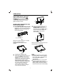
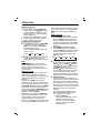
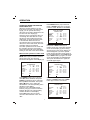
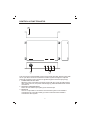
PLTV65R
OWNER'S MANUAL
Mobile Audio/Video System
AM/FM/MPX/TV-Tuner
PLL Synthesizer Stereo Radio
Built In Amplifier
Vertical Adjustable And Horizontal Rotatable Panel
Automatically Memory Storing
TFT Monitor
Remote Control
Optional TV Tuner (Separate Box)
CD Changer Control
4 x 40 Watts
www.pyleaudio.com
CONTENTS
Important Safety Instruction
3
Installation
4
DIN Front-Mount (Method A)
4
4
Installing the unit
Removing the unit
DIN Rear-Mount (Method B)
5
6
Wiring Connection
Operation
7
8
Location and function of keys
Switching on/off the unit
Automatic memory storing&
program scanning
Local/distant
Mono/stereo
Scan
CDC operation
Switching to CDC mode
Selecting tracks
Pausing playing
Previewing all tracks
Repeating the same track
Playing all tracks in random
Selecting disc
Operating when the monitor
stretching out
Menu control operation in
radio mode
Menu control operation in CDC
mode
TV operation
Switching to TV mode
Selecting receiving mode
Selecting channel
Menu control operation
Volume adjustment
Screen display
4:3/16:9 selector
Specification
Mobile TV Tuner Unit
Control & Function Keys
8
10
Open/close the monitor
Remote sensor
10
11
Liquid crystal display
11
6.5 inch TFT display
11
11
and angle adjustment
Reset function
Operating when the monitor not
stretching out
Sound mode selection
Adjusting the volume
11
11
11
Adjusting the treble
11
11
Adjusting the balance
11
Adjusting the fade
Adjusting the loud
11
12
Adjusting the equalization
Mute
12
12
Setting the clock
12
12
Adjusting the bass
Radio operation
Switching to radio mode
12
Selecting the frequency band
Selecting station
12
12
Setting memory
12
2
13
13
13
13
13
13
13
13
13
13
13
13
14
14
14
15
15
15
15
15
16
16
16
16
17
18
19
IMPORTANT SAFETY INSTRUCTION
CAUTION:
Please read and observe all warnings and
instructions given in this owner's manual.
Keep these instructions. Retain this
booklet for future reference.
Please read the following safety
instructions carefully.
1.This set has been designed and
manufactured to assure personal
safety. Improper use can result in
electric shock or fire hazard. The
safeguards incorporated in this unit
protect you if you observe the following
procedures for installation, use and
servicing. This unit doesn't contain any
parts that can be repaired by the user.
2.The monitor is operated automatically.
Do not draw the monitor out or turn it
upward or downward manually.
Otherwise, the mechanism
construction may be harmed to some
degree.
3.When you operate the monitor with
the remote handset, do not touch the
monitor by your hands. It may harm
your fingers.
3
INSTALLATION
TAKE OUT SCREW BEFORE
INSTALLATION
Notes:
Choose the mounting location where
the unit will not interfere with the
normal driving function of the driver.
Before finally installing the unit,
connect the wiring temporarily and
make sure it is all connected up
properly and the unit and the system
work properly.
Use only the parts included with the
unit to ensure proper installation. The
use of unauthorized parts can cause
Malfunctions.
Consult with your nearest dealer if
installation requires the drilling of
holes or other modifications of the
Vehicle.
Install the unit where it does not get
in the driver's way and cannot injure
the passenger if there is a sudden
stop,like an emergency stop.
If installation angle exceeds 30 from
horizontal, the unit might not give its
optimum performance.
Before install the unit, please remove
the two screws on the back of the unit.
Take out screw
before installation.
DIN FRONT-MOUNT (Method A)
Installation Opening
This unit can be installed in any
dashboard having an opening as show
below:
53mm
O
182mm
Installing the unit
Be sure you test all connections first, and
then follow these steps to install the unit.
30
Avoid installing the unit where it would
be subject to high temperature, such
as from direct sunlight, or from hot air,
from the heater, or where it would be
subject to dust, dirt or excessive
vibration.
DIN FRONT/REAR-MOUNT
This unit be can properly installed either
from "Front"(conventional DIN
Front-mount) or "Rear"(DIN Rear-mount
installation, utilizing threaded screw holes
at the sides of the unit chassis). For
details, refer to the following illustrated
installation methods.
4
1. Make sure the ignition is turned off,
and then disconnect the cable from the
vehicle battery's negative (-) terminal.
2. Disconnect the wire harness and the
Antenna.
3. Lift the top of the outer trim ring then
pull it out to remove it.
4. The two supplied keys release tabs
inside the unit's sleeve so you can
remove it. One key is for the right side
and the other is for the left side. Insert
the keys as far as they will go (with the
notches facing up) into the appropriate
slots at the middle left and right sides
of the unit. Then slide the sleeve off
the back of the unit.
INSTALLATION
(Tapping Screw (5x25mm) and Plain
Washer) to attach the other end of
metal strap to a solid metal part of the
vehicle under the dashboard. This
strap also helps ensure proper electrical
grounding of the unit.
Sleeve
L Key
Outer Trim Ring
R Key
Spring Washer Hex Nut
Metal Strap
5. Mount the sleeve by inserting the
sleeve into the opening of the
dashboard and bend open the tabs
located around the sleeve with a
screwdriver. Not all tabs will be able to
make contact, so examine which ones
will be most effective. Bending open
the appropriate tabs behind the
dashboard to secure the sleeve in
place.
Mounting Bolt
Plain Washer
Tapping Screw
9. Reconnect the cable to the vehicle
battery's negative (-) terminal. Then
replace the out trim ring.
Dashboard
Tabs
Removing the unit
1. Make sure the ignition is turned off,
then disconnect the cable from the
vehicle battery's negative (-) terminal.
2. Remove the metal strap attached the
back of the unit (if attached).
3. Lift the top of the outer trim ring then
pull it out to remove it.
4. Insert both of the supplied keys into the
slots at the middle left and right sides of
the unit, then pull the unit out of the
dashboard.
Screwdriver
any wires or cables.
Sleeve
6. Reconnect the wire harness and the
antenna and be careful not to pinch
any wires or cables.
7. Slide the unit into the sleeve until it
Locks into place.
8. To further secure the unit, use the
supplied metal strap to secure the back
of the unit in place. Use the supplied
hardware (Hex Nut (M5mm) and Spring
Washer) to attach one end of the strap
to the mounting bolt on the back of
the unit. If necessary, bend the metal
strap to fit your vehicle's mounting area.
Then use the supplied hardware
5
INSTALLATION
DIN REAR-MOUNT (Method B)
3
1
2
4
5
1.
2.
3.
4.
5.
Factory radio mounting bracket
Car radio mounting bracket
Screw
After aligning the car radio
mounting bracket with the factory
radio mounting bracket, tighten the
screws (5x5mm) at 2 places on
each side.
When fix the factory radio
mounting bracket with the screws,
use s standard-tipped screwdriver
to open the tabs of the car radio
mounting bracket to make them fit
into theholes in the factory radio
mounting bracket.
6
ELECTRICAL CONNECTION
MAIN UNIT
ANTENNA CONNECTOR
Rch RED
Lch WHITE
VIDEO YELLOW
Rch RED
Lch WHITE
VIDEO YELLOW
(BLACK)
CD CHANGER
CONNECTOR SOCKET
AV2 IN
(RED)
(GREY)
AV OUT
(GREEN)
R.G.B. IN
(BLUE)
EXTERNAL REMOTE CONTRL
IGNITION
SWITCH (ACC+)
MEMORY/
BATTERY(B+)
GROUND (B-)
(OPTIONAL)
(YELLOW)
SYNC IN
To the TV unit
with the 13-pin din Jack
(SEPARATE BOX)
(OPTIONAL)
PINK
RED
ORANGE
YELLOW
BLUE
BRAKE 1
BRAKE 2
POWER
ANTENNA
BLACK
FRONT Lch
SPEAKER
+
-
REAR Lch
SPEAKER
+
-
WHITE
GREY
WHITE/BLACK
GREY/BLACK
GREEN
VIOLET
GREEN/BLACK
VIOLET/BLACK
+
-
FRONT Rch
SPEAKER
+
-
REAR Rch
SPEAKER
Note: The Brake 1 wire is designed to connect to the ground wire, and the Brake 2
wire is designed to connect to CPU. Be sure that these two wires can't be connected
to other wires, especially the ACC+ wire and the B+ wire.
7
OPERATION
LOCATION AND FUNCTION OF KEYS
9
1
7
8
6
2
16
28
29
30 15 31
12
32
33
14
10
4
Fig.A
5
23
22
19
20
21
Fig.B
8
26
25 27 24
13
17
11
3
18
OPERATION
LOCATION AND FUNCTION OF KEYS
34
35
37
36
38
40
39
41
42
43
44
46
45
47
49
48
51
52
53
50
/
1.
2. OPEN/CLOSE
3. MUTE
4. LCD
5. TFT Monitor
6. SEL
7. VOLUME
8. VOLUME
9. Reset
10. IR
11. BND
12. MODE
13. TUNING
TUNING/TRACK (For CDC Version Only)
14. TUNING
TUNING/TRACK (For CDC Version Only)
15. M1~M6
16. MO/ST
17. AUDIO 1 IN
18. VIDEO 1 IN
19. MENU
20. DSP
21. TV/AV
22. VOLUME
23. VOLUME
24. CHANNEL
25. CHANNEL
26. IR
27. 4:3/16:9 Selector
28. PAU(For CDC Version Only)
29. INT(For CDC Version Only)
30. RPT(For CDC Version Only)
31. RDM(For CDC Version Only)
32. CD-(For CDC Version Only)
33. CD+(For CDC Version Only)
34.
POWER
35 OPEN
36. 0~9 Numeric Button
37. M1~M6
38. LOC
39. -/-- (SCAN)
40. BAND
41. TV/AV
42. MODE
43. MUTE
44. DISP
45. MENU
46. TUN/CH /
47. VOL /
48. AS/PS
49. PANEL+
50. PANEL51. EQ
52. LOUD
53. ST/MO
9
OPERATION
SWITCHING ON/OFF THE UNIT
Switch on the unit by pressing /
POWER button (1) on the front panel
or POWER button (34) on the remote
control. When system is on, press it
again to turn the unit off.
OPEN/CLOSE THE MONITOR AND
ANGLE ADJUSTMENT
Press OPEN/CLOSE button (2) on the
front panel or point the remote control
to IR (10) on the front panel and press
OPEN button (35), the monitor will
stretch automatically.
Fig.3
Return the monitor to the central
viewing position, then press
OPEN/CLOSE button (2) on the
front panel or press OPEN button
(35) on the remote control, the
monitor will turn downward
automatically.
OPEN/CLOSE button
Fig.1
When the monitor stretches to a certain
location, it will turn upward
automatically and stop at vertical
position.
Fig.4
When the monitor turns downward to a
certain angle, it will draw in.
Fig.5
Fig.2
Adjusting the viewing angle.
When the monitor doesn't move, you
can press ANGLE+ button (49) or
ANGLE button (50) on the remote
control to turn the monitor upward or
downward at fine steps to get a
desired viewing angle. And you can
rotate the monitor left and right from
the central viewing position at a
certain angle range manually.
Don't rotate the monitor forcibly to
avoid mechanical damage.
10
NOTE:
When the monitor is on the central
viewing position, switch the ignition
key to "ACC OFF", the monitor will
turn downward and draw in
automatically.
When the monitor is on the central
viewing position, disconnect the
battery cable and then reconnect the
battery cable, the monitor will turn
downward and draw in automatically.
OPERATION
REMOTE SENSOR
There is a remote sensor IR (10) on the
front panel. On the monitor, there is
another remote sensor IR (26) to
receive remote control signal. You can
point the remote control handset to IR
(10) (when the monitor doesn't stretch
out) or IR (26) (when the monitor
stretches out) and press function keys
on the remote control to control the TV
unit.
The unit is also connected to an
external remote receiver (See the
electrical connection diagrams on Page
7), and the function is the same with IR
(10) and (26).
Notes:
The external remote receiver is
placed near the monitor for the best
to receiver remote signal easily.
If the angle of the monitor from
vertical exceeds 20 (Especially the
distance exceeds 3m.), controlling
the TV through IR (10) or (26) cannot
get good effect. You are suggested to
use the external remote receiver.
LIQUID CRYSTAL DISPLAY
The LCD (4) can show the current state of
the unit.
6.5 inch TFT DISPLAY
When the monitor stretches out, the 6.5
inch color TFT display (5) can show the
current state of the unit.
RESET FUNCTION
Reset button (9) must be activated with
either a ballpoint pen or thin metal object.
The reset button is to be activated for the
following reasons:
Initial installation of the unit when all
wiring is completed.
All the function buttons do not
operate.
Error symbol on the display.
Note: When the monitor stretches out and
on the central viewing position,
activate the reset button (9), the monitor
will turn downward and draw in
automatically.
11
OPERATING WHEN THE MONITOR
NOT STRETCHING OUT
When the monitor doesn't stretch out,
the front panel of the unit is in state A
(see Fig.A), you can operate the unit
following the instructions below.
Sound mode selection
Press SEL button (6) on the front
panel or MENU button (45) on the
remote control to enter sound mode
then pres sTUNING / buttons
(13&14) or TUN/CH / buttons
(46) to switch between volume, bass,
treble, balance, fader, loud and
equalization mode.
When mode has not been adjusted
for several seconds, display returns
to previous display status.
VOL
BAS
(Volume) (Bass)
EQ mode
TRE
BAL
FAD
(Treble) (Balance) (Fader)
LOUD mode
Adjusting the volume
Press SEL button (6) or MENU button
(45) then press TUNING / buttons
(13&14) or TUN/CH / buttons (46)
to enter volume mode, and then adjust
volume level using VOLUME / buttons
(7&8) or VOL / buttons (47).
Adjusting the bass
In bass mode, adjust bass level using
VOLUME / buttons (7&8) or VOL /
buttons (47).
Adjusting the treble
In treble mode, adjust treble level using
VOLUME / buttons (7&8) or VOL /
buttons (47).
Adjusting the balance
In balance mode, adjust sound balance
between left and right speakers using
VOLUME / buttons (7&8) or VOL /
buttons (47).
Adjusting the fader
In fader mode, adjust sound balance
between front and rear speakers using
VOLUME / buttons (7&8) or VOL /
buttons (47).
OPERATION
Adjusting the loud
In loud mode, use VOLUME /
buttons (7&8) or VOL / buttons(47)
to switch between loud on and off.
When LOUD on, "LOUD" will show
on the display (4).
Directly press LOUD button (52) to
reinforce the bass output. Press it
again to release the function.
Adjusting the equalization
In equalization mode, use VOLUME
/ buttons (7&8) or VOL /
buttons (47) to switch between the
following mode and the
corresponding information appears
on the LCD (4).
FLAT POP JAZZ CLAS
LCD remains the previous state and the
clock will not appear. You should press
DISP button once again to display the
clock.
Radio operation
Switching to radio mode
Press MODE button (12) on the front
panel or MODE button (42) on the
remote control to select radio mode,
the radio mode appears in the display
together with the memory band and
frequency.
Selecting the frequency band
Press BND button (11) on the front
panel or BAND button (40) on remote
control to select desired band. The
reception band will change in the
following order:
Directly press EQ button (51) to turn
on equalization function and to
select desired audio mode as above.
Mute
Press MUTE button (3) on the front
panelor MUTE button (43) on remote
control to cut down sound output.
Press it again to resume the previous
volume mode.
Setting the clock
Press DISP button (44) to change the
display into clock display. While the
current time is appeared on the LCD (4),
press it again to return to frequency
showing.
Holding down DISP button (44) for
several seconds, and the time for hours
is blinking on the display (4), then press
VOLUME / buttons (7&8) or VOL /
buttons (47) to switch between hours
and minutes. Press TUNING / buttons
(13&14) or TUN/CH / buttons (46) to
adjust the hours or minutes.
Note: When you first press DISP button
(44), the clock will appear on the LCD,
after several seconds, the clock will
disappear and the LCD enter into
frequency showing if you don't operate it.
Then you press DISP button again, the
12
FM1
FM2
FM3
AM1
AM2
Selecting station
During radio mode, press TUNING
button (13) or TUN/CH button on
remote control to increase frequency
or TUNING button (14) or
TUN/CH button on remote control
to decrease frequency by one step of
channel spacing. Hold the button
longer for fast tuning. The frequency
is updated correspondingly on display.
Setting memory
Press preset memory buttons (1~6)
(15)on the front panel or Radio Preset
buttons(1~6) (37) on remote control
to preset stations at radio mode. With
this system, a total of 30 stations can
be stored in the memory of six buttons.
Each band stores up to six preset
stations.
The stations might be FM1, FM2,
FM3, AM1/MW and AM2/LW band.
The operation is as below:
- Store in Memory
Press and hold desired memory
location button for several
seconds. The current listening
station will be stored into the
number button.
OPERATION
-
signal and keep on each station for
several seconds. At this time, press
any one of the buttons (15) on the
front panel or (37) on remote control,
the current scanned station will be
stored into the corresponding number
button, then it keeps on scanning
other stations.
Retrieve a Preset Station
Press any one of the buttons (15)
on the front panel or (37) on
remote control to retrieve a
station which had been stored in
the memory in advance the
chosen number is shown on
display.
CDC operation
Switching to CDC mode
Press MODE button (12) on the front
panel or MODE button (42) on the
remote control to select CDC mode.
Selecting tracks
Press TUNING/TRACK button (14)
on the front panel to move to the
previous track; press TUNING/
TRACK button (13) on the front
pane lto move to the next track. The
track number shows on the display(4).
Pausing playing
Press PAU button (28) on the front
panel to pause CD play. Press it
again to resume play.
Previewing all tracks
Press INT button (29) on the front
panel to play the first 10 seconds of
each track on the current disc. Press
it again to stop intro and listen to
track.
Repeating the same track
Press RPT button (30) on the front
panel to continuously repeat the
same track on the current disc. Press
it again to stop repeating.
Playing all tracks in random
Press RDM button (31) on the front
panel to play all tracks on the current
CD in random order. Press it again to
cancel the mode. In the course of
playing a track, press TUN/CH /
buttons (46) to play another track in
random order.
Selecting disc
Press CD+ button (33) on the front
panel to select next disc and press
CD- button (32) on the front panel to
select previous disc.
Automatic memory storing &
program scanning
- Automatic memory storing
Press AS/PS button (48) for
several seconds, the radio
searches from the current
frequency and checks the signal
strength until one cycle search is
finished. And then 6 strongest
stations are stored into the
corresponding preset number
button.
- Program scanning
Press AS/PS button (48) shortly
to scan preset station. When the
field strength level is more than
the threshold level of stop level.
The radio is holding at that
preset number for several
seconds with release mute, then
searches again.
Local/distant
Press LOC button (38) on remote
control to select between local and
distant stations.
Local setting for reception of strong
station, and a distant setting for
reception of weaker stations. This
function is effect during AUTO SEEK
operation.
Mono/stereo
Press MO/ST button (16) on the front
panel or ST/MO button (53) on remote
control to select mono or stereo mode.
You can sometimes improve reception
of distant stations by selecting mono
operation.
Scan
Press -/-- (SCAN) button (39) on
remote control to set the function to
scan mode, which scanning to higher
frequency station with receivable
13
OPERATION
Press MO/ST button (16) on the front
panel or ST/MO button (53) on remote
control to select "MONO" or "STEREO".
OPERATING WHEN THE MONITOR
STRETCHING OUT
When the monitor stretches out, the
front panel of the unit is in state B (see
Fig.B), you can operate the unit by
using the current menu displayed on the
6.5 inch color TFT display (5).
And if the unit is connected to other TV
unit through the cable with the 13-pin
din plug on each terminal, there have
radio mode, TV mode and CDC mode
to be selected. When the unit isn't
connected to other TV unit through the
cable, there have radio mode, AV mode
and CDC mode to be selected.
The other operations are the same with
the operation when the front panel in
state A and those will not be described
below,you can refer to the above details.
FM1 98.10 MHz
MONO LOC
VOLUME
BASS
TREBLE
BALANCE
FADER
LOUD
EQ
Menu Control operation in radio mode
Press MODE button (12) on front panel or
MODE button (42) on remote control to
select radio mode. The following
information will appear on the display (5).
36
0
0
L-R
F-R
OFF
FLAT
M1 87.50
M2 90.10
M3 98.10
M4 106.10
M5 108.00
M6 87.50
When press DSP button (20) on the
front panel or DISP button (44) on
remote control, the current time appears
on the screen display (5) and LCD (4).
And the clock on the screen display (5)
will not disappear if you don't operate
it after several seconds, but the clock on
the LCD will disappear. Press DSP button
(20) or DISP button (44) again, the clock
on the screen display (5) will disappear.
Then press the button once again, the
clock will appear again.
FM1 87.5 MHz
STEREO DX
FM1 87.5 MHz
STEREO DX
VOLUME
BASS
TREBLE
BALANCE
FADER
LOUD
EQ
30
2
2
L-R
F-R
ON
POP
M1 87.50
M2 90.10
M3 98.10
M4 106.10
M5 108.00
M6 87.50
VOLUME
BASS
TREBLE
BALANCE
FADER
LOUD
EQ
Press MENU button (19) or (45), the
VOLUME will be selected, then press
TUN/CH / buttons (46) to select the
item upward or downward. Then press
VOL / buttons (47) to adjust the
selected item. The corresponding value
will show on the display.
Press any one of the Radio Preset
buttons (1~6) (37) to retrieve a station
between M1~M6. The corresponding
number will show on the display.
Press LOC button (38) on remote
contro lto select between "LOC" and
"DX".
36
0
0
L-R
F-R
OFF
FLAT
10:12:22
M1 87.50
M2 90.10
M3 98.10
M4 106.10
M5 108.00
M6 87.50
When the clock appears on the screen
display, hold DSP button (20) or DISP
button (44) to select 10 for hours:
FM1 87.5 MHz
STEREO DX
VOLUME
BASS
TREBLE
BALANCE
FADER
LOUD
EQ
14
36
0
0
L-R
F-R
OFF
FLAT
10:12:22
M1 87.50
M2 90.10
M3 98.10
M4 106.10
M5 108.00
M6 87.50
OPERATION
Then you can press VOL / buttons
(48) to select hour or minute and press
TUN/CH / buttons (47) to change the
corresponding item.
Menu Control operation in CDC mode
Press MODE button (12) on front panel
or MODE button (43) to select CDC
mode. The following information will
appear on the display (5).
CDC
PLAY
VOLUME
BASS
TREBLE
BALANCE
FADER
LOUD
EQ
00:12
36
0
0
L-R
F-R
OFF
FLAT
DISC
TRACK
01
01
Press MENU button (19) or (45), the
VOLUME will be selected, then press
TUN/CH / buttons (46) to select the
item upward or downward. Then press
VOL / buttons (48) to adjust the
selected item. The corresponding value
will show on the display.
Respectively press PAU (28), INT (29),
RPT (30), RDM (31), CD- (32), CD+ (33)
button on the panel to enter the
corresponding function referring to the
CDC operation described above, the
corresponding information (such as
PAUSE, INTRO, REPEAT, RANDOM and
the disc number) will appear on the
display (5).
CDC
PLAY
VOLUME
BASS
TREBLE
BALANCE
FADER
LOUD
EQ
00:24
36
0
0
L-R
F-R
OFF
FLAT
DISC
TRACK
03
02
REPEAT
15
Directly press TUNING/TRACK button
(14) on the panel to move to the s
previou track; press TUNING/TRACK
button (13) on the panel control to move
to the next track.
TV operation (when the unit is
connected to other TV unit through
the cable with the 13-pin din plug on
each terminal)
Switching to TV mode
Press MODE button (12) on the front
panel or MODE button (42) on remote
control to select TV mode and the
memory channel will show on the TFT
display (5).
Selecting receiving mode
In TV mode, press TV/AV button (21)
or (41) to select among TV/ AV1/AV2/
RGB (optional). The corresponding
state will show on the TFT display (5).
When you connect the RGB terminals
on the back of the unit to the
corresponding RGB system, then
press MODE button on remote
control to select RGB mode, the RGB
signal will appear on the screen.
Note: You can receive the TV/AV1
/AV2 mode when you brake the car.
If you are driving the car, you can't
receive the picture signal in TV/AV1
/AV2 just receive the sound signal, it
is blue screen then.
Selecting channel
- Press CHANNEL button (24) or
TUN/CH button on remote
control to choose channel upward
and or Press CHANNEL button
(25) or TUN/CH button on
remote control to choose channel
downward.
- The numeric buttons (0,1~9) (36)
allow you to select the
corresponding channel directly.
- Press digital select button (-/--) (39)
cooperatively used with numeric
buttons to select channel desired.
For example, when you want
select 16 channel, press -/-- (39)
to switch between "-" and "--",
when the "--" appears on the
OPERATION
display, you can press "1 "button
then press "6" button to select 16
channel.
Menu control operation
In TV mode:
Press MENU button (19) or (45). The
menu will show on the display (5).
Volume adjustment
Press VOLUME / buttons (23&22)
or VOL / buttons (47) to adjust
volume level.
Screen display
Press DSP button (20) on the front
panel or DISP button (44) on remote
control to display the current status
such as TVch /AV1/AV2. Press DSP
button (20) or DISP button (44) again
to show the current time. If you don't
operate over 5 seconds, the
information on the screen will
disappear.
4:3/16:9 Selector
Slide the 4:3/16:9 switch (27) on the
monitor panel to select appropriate
TV aspect (4:3 or 16:9).
(For the unit with NTSC system):
COLOR
BRIGHT
CONTRAST
TINT
SEARCH
40
40
40
40
Press TUN/CH / buttons (46) to
select the item upward or downward.
Then press VOL / buttons (47) to
adjust the selected item. The
corresponding value will show on the
display.
When select SEARCH item, press
VOL / buttons (47) to start auto
searching then press TUN/CH
button on remote control to stop
searching.
In AV mode:
Press MENU button (19) or (45). The
menu will show on the display (5).
(For the unit with NTSC system):
COLOR
BRIGHT
CONTRAST
TINT
40
40
40
40
Press TUN/CH / buttons (46) to
select the item upward or downward.
Then press VOL / buttons (47) to
adjust the selected item. The
corresponding value will show on the
display.
16
SPECIFICATION
GENERAL
Power Supply Requirements
Maximum Output Power
Current Drain
: DC 12 Volts, Negative Ground
: 4x40 watts
: 15 Ampere (max.)
TV
Monitor Screen Size
Resolution
TV Sensitivity
: 6.5" TFT
: 1440 x 234 dots
: 45dB V @CH25 in average
RADIO
Frequency Coverage
Sensitivity (S/N=30dB)
Image Rejection
Stereo Separation
FM
87.5 to 107.9 MHz
4 V
>45dB
>25dB
Frequency Coverage
Sensitivity (S/N=20dB)
Image Rejection
AM
530 to 1720 kHz
36 dBu
45 dB
17
MOBILE TV TUNER UNIT
18
CONTROL & FUNCTION KEYS
1
3
2
This unit can't be used separately and it must be used with other special system with
the 13 -pin cable. The unit is connected to another system through the 13-pin din
socket (3). And the unit can receive TV signal through the antenna input jack (2).
1 POWER INDICATOR LIGHT
When the unit is connected to the other system with the 13-pin din cable and the
other system turns on, the power indicator light (1) will be illuminated red and the
unit turns on.
2 DIVERSITY ANTENNA INPUT
There are four antenna input jacks (2) for antenna input.
3 MONITOR
Use one 13-pin cable to connect the unit and other system. One terminal is
connected to the 13-pin din socket (3) of the unit and the other terminal is
connected to other system.
19
www.pyleaudio.com
88-T1690-04