1
_________________________________________________________Zaxcom Deva User’s Manual
Table of Contents
TABLE OF FIGURES ............................................................................................................................................. 17
TABLE OF TABLES ............................................................................................................................................... 18
CHAPTER 1 – INTRODUCTION......................................................................................................................... 19
OVERVIEW .................................................................................................................................................................................................. 19
USER MANUAL CONVENTIONS ................................................................................................................................................................ 19
SYSTEM FEATURES ...................................................................................................................................................................................... 19
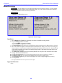
Deva-5.8 Specific ....................................................................................................................................................................................................... 19
Deva-16 Specific ........................................................................................................................................................................................................ 19
Common Features...................................................................................................................................................................................................... 20
WHAT’S INCLUDED WITH THE DEVA-5.8................................................................................................................................................ 20
Deva-5.8 Options ....................................................................................................................................................................................................... 20
WHAT’S INCLUDED WITH THE DEVA-16................................................................................................................................................. 21
Deva-16 Options ........................................................................................................................................................................................................ 21
DEVA SOFTWARE RECOMMENDATIONS .................................................................................................................................................. 21
MEDIA / ACCESSORY RECOMMENDATIONS ............................................................................................................................................. 21
Hard Disk Drives ....................................................................................................................................................................................................... 21
CompactFlash Cards ................................................................................................................................................................................................. 21
FireWire Devices ........................................................................................................................................................................................................ 22
Harddisk Drive ....................................................................................................................................................................................................... 22
CompactFlash Reader/Drive................................................................................................................................................................................ 22
Keyboards .................................................................................................................................................................................................................... 22
TOUCHSCREEN INTERFACE ....................................................................................................................................................................... 22
ANALOG INPUTS ........................................................................................................................................................................................ 22
ANALOG INPUT LIMITER............................................................................................................................................................................ 22
DIGITAL INPUTS ......................................................................................................................................................................................... 22
MIXING ....................................................................................................................................................................................................... 22
RECORDING ............................................................................................................................................................................................... 22
CAMERA / LINE IN CONNECTOR.............................................................................................................................................................. 22
Deva-5.8 ....................................................................................................................................................................................................................... 22
Deva-16 ........................................................................................................................................................................................................................ 23
METERING ................................................................................................................................................................................................... 23
FIREWIRE PORT.......................................................................................................................................................................................... 23
RF INTERFERENCE PROTECTION .............................................................................................................................................................. 23
TIMECODE .................................................................................................................................................................................................. 23
INPUT SAMPLING-RATE CONVERSION ..................................................................................................................................................... 23
SEQUENCE OF DEVA COMPONENTS ........................................................................................................................................................ 23
PRODUCT SUPPORT ................................................................................................................................................................................... 24
CHAPTER 2 – EXTERIOR DESCRIPTION ......................................................................................................... 25
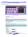
FRONT PANEL DESCRIPTION .................................................................................................................................................................... 25
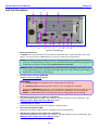
LEFT SIDE DESCRIPTION ............................................................................................................................................................................ 27
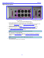
RIGHT SIDE DESCRIPTION ......................................................................................................................................................................... 29
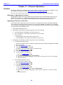
CHAPTER 3 – SOFTWARE GUIDE .................................................................................................................... 30
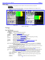
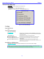
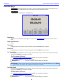
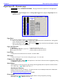
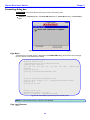
BOOT-UP SEQUENCE PAGE ....................................................................................................................................................................... 30
Page Notes................................................................................................................................................................................................................... 30
Page Level Shortcuts.................................................................................................................................................................................................. 30
Boot Keys ..................................................................................................................................................................................................................... 30
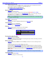
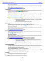
MENU NAVIGATION .................................................................................................................................................................................. 31
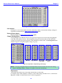
INDEX OF NOMAD PAGES ......................................................................................................................................................................... 31
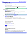
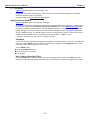
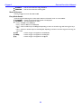
INDEX OF DEVA SCREEN OBJECTS ........................................................................................................................................................... 32
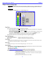
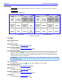
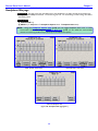
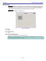
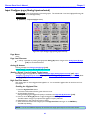
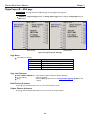
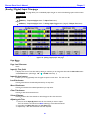
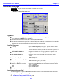
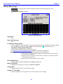
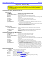
HOME PAGE ................................................................................................................................................................................................ 35
Page Notes................................................................................................................................................................................................................... 35
Page Level Shortcuts.................................................................................................................................................................................................. 35
2
Zaxcom Deva User’s Manual_________________________________________________________
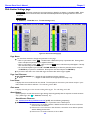
Using the Deva front panel: ................................................................................................................................................................................. 35
Using the Mix-12 embedded keyboard: ............................................................................................................................................................ 36
Using an attached keyboard: ................................................................................................................................................................................ 36
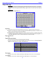
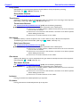
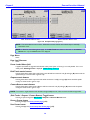
Enter Segment data entry field .............................................................................................................................................................................. 37
Enter Segment data entry field Shortcuts ......................................................................................................................................................... 37
Mode Status button................................................................................................................................................................................................... 37
View button .................................................................................................................................................................................................................. 37
Timecode button ........................................................................................................................................................................................................ 37
Disk icon ....................................................................................................................................................................................................................... 37
Remaining Recording Time field ............................................................................................................................................................................ 37
Battery icon button .................................................................................................................................................................................................... 37
Sampling-rate field ..................................................................................................................................................................................................... 37
Timecode Frame-rate field ...................................................................................................................................................................................... 38
Pre-record Duration field.......................................................................................................................................................................................... 38
Headphone button .................................................................................................................................................................................................... 38
Mirror Drive Status button ...................................................................................................................................................................................... 38
Cur Segs Folder button ............................................................................................................................................................................................. 38
Cur field.................................................................................................................................................................................................................... 38
Segs field ................................................................................................................................................................................................................... 38
Folder field ............................................................................................................................................................................................................... 38
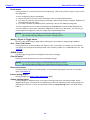
S: T: N: button.......................................................................................................................................................................................................... 39
Input (#) meters & buttons .................................................................................................................................................................................... 39
Solo Mode ................................................................................................................................................................................................................ 39
Arm / Disarm a Recording Track ....................................................................................................................................................................... 39
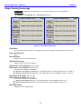
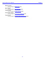
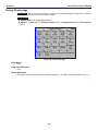
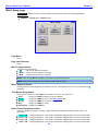
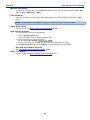
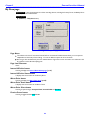
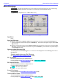
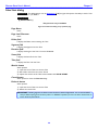
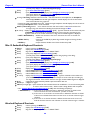
MAIN MENU PAGE ...................................................................................................................................................................................... 40
Page Notes................................................................................................................................................................................................................... 40
Page Level Shortcuts.................................................................................................................................................................................................. 40
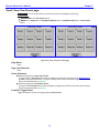
Mode Status button................................................................................................................................................................................................... 40
Disk Mix button.......................................................................................................................................................................................................... 40
Output Mix button..................................................................................................................................................................................................... 40
Faders button .............................................................................................................................................................................................................. 40
Time Code button ...................................................................................................................................................................................................... 40
Setup button ................................................................................................................................................................................................................ 40
Input Configure button ............................................................................................................................................................................................. 40
My Deva button ......................................................................................................................................................................................................... 41
Cue Mode button ....................................................................................................................................................................................................... 41
Tone button ................................................................................................................................................................................................................. 41
Head Phone Mix button........................................................................................................................................................................................... 41
Scene Take Note button .......................................................................................................................................................................................... 41
About Deva button .................................................................................................................................................................................................... 41
Additional Functionality ............................................................................................................................................................................................. 41
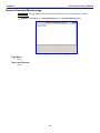
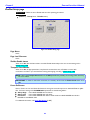
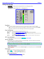
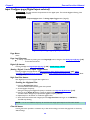
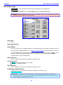
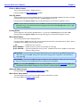
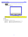
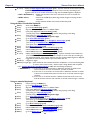
DISK MIX PAGE ........................................................................................................................................................................................... 42
Page Notes................................................................................................................................................................................................................... 42
Page Level Shortcuts.................................................................................................................................................................................................. 42
Disk Mix matrix buttons .......................................................................................................................................................................................... 42
Slate buttons ............................................................................................................................................................................................................... 42
Tone buttons ............................................................................................................................................................................................................... 42
Preset button ............................................................................................................................................................................................................... 43
(Analog / Digital) In Toggle button ........................................................................................................................................................................ 43
(Pre- / Post-) Fader button ....................................................................................................................................................................................... 43
-MORE- button ........................................................................................................................................................................................................... 43
Clear All button ........................................................................................................................................................................................................... 43
Phase Invert button ................................................................................................................................................................................................... 43
Limiter Settings button.............................................................................................................................................................................................. 43
Limiting button ............................................................................................................................................................................................................ 44
(Up / Down) Arrow button (Deva-16 only) .................................................................................................................................................... 44
Limit buttons................................................................................................................................................................................................................ 44
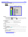
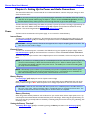
DISK LIMITER SETTINGS PAGE ................................................................................................................................................................... 45
Page Notes................................................................................................................................................................................................................... 45
Page Level Shortcuts.................................................................................................................................................................................................. 45
3
_________________________________________________________Zaxcom Deva User’s Manual
Level meter .................................................................................................................................................................................................................. 45
Gain meter ................................................................................................................................................................................................................... 45
Attack button .............................................................................................................................................................................................................. 45
Attack button Shortcuts ....................................................................................................................................................................................... 45
Decay button ............................................................................................................................................................................................................... 46
Decay button Shortcuts........................................................................................................................................................................................ 46
Thresh button .............................................................................................................................................................................................................. 46
Thresh button Shortcuts ...................................................................................................................................................................................... 46
Ratio button ................................................................................................................................................................................................................. 46
Ratio button Shortcuts ......................................................................................................................................................................................... 46
Gain button .................................................................................................................................................................................................................. 46
Gain button Shortcuts........................................................................................................................................................................................... 46
Inc button ..................................................................................................................................................................................................................... 46
Dec button ................................................................................................................................................................................................................... 46
OUTPUT MIX PAGE .................................................................................................................................................................................... 47
Page Notes................................................................................................................................................................................................................... 47
Page Level Shortcuts.................................................................................................................................................................................................. 47
Output Mix matrix buttons ..................................................................................................................................................................................... 47
Slate buttons ............................................................................................................................................................................................................... 47
Tone buttons ............................................................................................................................................................................................................... 47
Preset button ............................................................................................................................................................................................................... 48
(Analog / Digital) In Toggle button ........................................................................................................................................................................ 48
(Pre- / Post-) Fader button ....................................................................................................................................................................................... 48
-MORE- button ........................................................................................................................................................................................................... 48
Clear All button ........................................................................................................................................................................................................... 48
Phase Invert button ................................................................................................................................................................................................... 48
Limiter Settings button.............................................................................................................................................................................................. 48
Output Limiting button ............................................................................................................................................................................................. 48
Limit buttons................................................................................................................................................................................................................ 49
Routing Presets button .............................................................................................................................................................................................. 49
Output Routing button.............................................................................................................................................................................................. 49
Play buttons ............................................................................................................................................................................................................. 49
Stop buttons ............................................................................................................................................................................................................ 50
Rec buttons ............................................................................................................................................................................................................. 50
OUTPUT LIMITER SETTINGS PAGE ............................................................................................................................................................. 51
Page Notes................................................................................................................................................................................................................... 51
Page Level Shortcuts.................................................................................................................................................................................................. 51
Level meter .................................................................................................................................................................................................................. 51
Gain meter ................................................................................................................................................................................................................... 51
Attack button .............................................................................................................................................................................................................. 51
Attack button Shortcuts ....................................................................................................................................................................................... 51
Decay button ............................................................................................................................................................................................................... 52
Decay button Shortcuts........................................................................................................................................................................................ 52
Thresh button .............................................................................................................................................................................................................. 52
Thresh button Shortcuts ...................................................................................................................................................................................... 52
Ratio button ................................................................................................................................................................................................................. 52
Ratio button Shortcuts ......................................................................................................................................................................................... 52
Gain button .................................................................................................................................................................................................................. 52
Gain button Shortcuts........................................................................................................................................................................................... 52
Inc button ..................................................................................................................................................................................................................... 52
Dec button ................................................................................................................................................................................................................... 52
OUTPUT ROUTING PRESETS PAGE ............................................................................................................................................................ 53
Page Notes................................................................................................................................................................................................................... 53
Page Level Shortcuts.................................................................................................................................................................................................. 53
Normal button ............................................................................................................................................................................................................ 53
Play Switches button.................................................................................................................................................................................................. 53
Play Tracks 1-6, 15-16 button (Deva-16 only) ................................................................................................................................................ 53
Play Tracks 1-6, 9-10 button (Deva-5.8 only).................................................................................................................................................. 53
Play Tracks 9-16 button (Deva-16 only)............................................................................................................................................................ 53
Play Tracks 3-10 button (Deva-5.8 only)........................................................................................................................................................... 53
4
Zaxcom Deva User’s Manual_________________________________________________________
Mute Play button........................................................................................................................................................................................................ 53
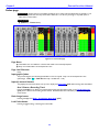
FADERS PAGE .............................................................................................................................................................................................. 54
Page Notes................................................................................................................................................................................................................... 54
Page Level Shortcuts.................................................................................................................................................................................................. 54
Input graphic faders .................................................................................................................................................................................................. 54
Input (#) meters & buttons .................................................................................................................................................................................... 54
Arm / Disarm a Recording Track ....................................................................................................................................................................... 54
Fader Assign button ................................................................................................................................................................................................... 54
Lock Faders button .................................................................................................................................................................................................... 54
(KNOB / TOUCH) FADER ASSIGN PAGE ................................................................................................................................................... 55
Page Notes................................................................................................................................................................................................................... 55
Page Level Shortcuts.................................................................................................................................................................................................. 56
Knob Assign matrix buttons .................................................................................................................................................................................... 56
Touch Fader Assign matrix buttons ...................................................................................................................................................................... 56
Preset button ............................................................................................................................................................................................................... 56
(Analog / Digital) In Toggle button ........................................................................................................................................................................ 56
(Fader / ZaxNet Trim) button ................................................................................................................................................................................ 56
Clear All button ........................................................................................................................................................................................................... 56
Fader Assign Toggle button ..................................................................................................................................................................................... 56
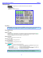
TIMECODE PAGE ......................................................................................................................................................................................... 57
Page Notes................................................................................................................................................................................................................... 57
Page Level Shortcuts.................................................................................................................................................................................................. 57
Reader T.C. field ......................................................................................................................................................................................................... 57
Reader U.B. field ........................................................................................................................................................................................................ 57
Generator T.C. field ................................................................................................................................................................................................... 57
Generator U.B. field ................................................................................................................................................................................................... 57
Timecode Out button ................................................................................................................................................................................................ 57
Timecode Displayed button..................................................................................................................................................................................... 58
Timecode Run Mode button ................................................................................................................................................................................... 58
Frame Rate button .................................................................................................................................................................................................... 58
Enter Timecode button ............................................................................................................................................................................................. 58
Enter Timecode button Shortcuts ..................................................................................................................................................................... 58
Enter User Bits button .............................................................................................................................................................................................. 58
Enter User-Bits button Shortcuts....................................................................................................................................................................... 58
Increment User Bits button ..................................................................................................................................................................................... 58
JAM T.C. button .......................................................................................................................................................................................................... 58
JAM U.B. button ......................................................................................................................................................................................................... 58
JAM Date button ........................................................................................................................................................................................................ 58
JAM Time button ........................................................................................................................................................................................................ 58
DUAL RATE TIMECODE ......................................................................................................................................................................................... 58
TIMECODE RUN MODE PAGE .................................................................................................................................................................... 59
Page Notes................................................................................................................................................................................................................... 59
Page Level Shortcuts.................................................................................................................................................................................................. 59
Timecode Runmode buttons ................................................................................................................................................................................... 59
Auto JAM Date at Midnight button....................................................................................................................................................................... 59
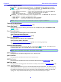
SETUP PAGE................................................................................................................................................................................................. 60
Page Notes................................................................................................................................................................................................................... 60
Page Level Shortcuts.................................................................................................................................................................................................. 60
Sample Rate button .................................................................................................................................................................................................. 60
Record Channels button ........................................................................................................................................................................................... 60
Pre-Record Time button ........................................................................................................................................................................................... 60
Tone Level button ...................................................................................................................................................................................................... 60
Operating Modes button.......................................................................................................................................................................................... 60
Meters button ............................................................................................................................................................................................................. 60
Headphone Options button .................................................................................................................................................................................... 60
Clock button ................................................................................................................................................................................................................ 60
Memory button ........................................................................................................................................................................................................... 61
Mix12 button .............................................................................................................................................................................................................. 61
ZaxNet button ............................................................................................................................................................................................................ 61
5
_________________________________________________________Zaxcom Deva User’s Manual
User Interface button................................................................................................................................................................................................ 61
Service button ............................................................................................................................................................................................................. 61
SAMPLE RATE PAGE .................................................................................................................................................................................... 62
Page Notes................................................................................................................................................................................................................... 62
Page Level Shortcuts.................................................................................................................................................................................................. 62
Sample-rate buttons .................................................................................................................................................................................................. 62
Sample Rate Reference button .............................................................................................................................................................................. 62
RECORD TRACK SELECT PAGE .................................................................................................................................................................. 63
Page Notes................................................................................................................................................................................................................... 63
Page Level Shortcuts.................................................................................................................................................................................................. 63
Two Track button ...................................................................................................................................................................................................... 63
Four Track button ...................................................................................................................................................................................................... 63
Tracks Mixed To button........................................................................................................................................................................................... 63
All Tracks button ........................................................................................................................................................................................................ 63
Tracks to Record buttons......................................................................................................................................................................................... 63
OPERATING MODE PAGE........................................................................................................................................................................... 64
Page Notes................................................................................................................................................................................................................... 64
Page Level Shortcuts.................................................................................................................................................................................................. 64
Transport Operation button .................................................................................................................................................................................... 64
GPi1 Remote Roll button ......................................................................................................................................................................................... 64
Serial Remote Roll button ........................................................................................................................................................................................ 64
Serial Port Mode button ........................................................................................................................................................................................... 64
Slate Source button ................................................................................................................................................................................................... 65
B-Format button ......................................................................................................................................................................................................... 65
Command Monitor button....................................................................................................................................................................................... 65
REMOTE COMMAND MONITOR PAGE...................................................................................................................................................... 66
Page Notes................................................................................................................................................................................................................... 66
Page Level Shortcuts.................................................................................................................................................................................................. 66
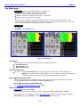
METER MENU PAGE .................................................................................................................................................................................... 67
Page Notes................................................................................................................................................................................................................... 67
Page Level Shortcuts.................................................................................................................................................................................................. 67
Number of Home Screen Meters button ............................................................................................................................................................ 67
Meter Vertical / Horizontal button ....................................................................................................................................................................... 67
Color Schemes button ............................................................................................................................................................................................... 68
Meter Labels button .................................................................................................................................................................................................. 68
Display Inputs button ................................................................................................................................................................................................ 68
Display Outputs button ............................................................................................................................................................................................ 68
Meter Mode button................................................................................................................................................................................................... 68
Meter Assigns button ................................................................................................................................................................................................ 68
METER LABELS PAGE ................................................................................................................................................................................... 69
Page Notes................................................................................................................................................................................................................... 69
Page Level Shortcuts.................................................................................................................................................................................................. 69
Meter (#) Label buttons........................................................................................................................................................................................... 69
Meter (#) Label buttons Shortcuts .................................................................................................................................................................... 69
INPUT METER MENU PAGE ........................................................................................................................................................................ 70
Page Notes................................................................................................................................................................................................................... 70
Page Level Shortcuts.................................................................................................................................................................................................. 70
Input Level meters ..................................................................................................................................................................................................... 70
OUTPUT METER MENU PAGE .................................................................................................................................................................... 71
Page Notes................................................................................................................................................................................................................... 71
Page Level Shortcuts.................................................................................................................................................................................................. 71
Output Level meters.................................................................................................................................................................................................. 71
METER ASSIGNMENTS PAGE....................................................................................................................................................................... 72
Page Notes................................................................................................................................................................................................................... 72
Page Level Shortcuts.................................................................................................................................................................................................. 72
Meter (#) Assignment buttons ............................................................................................................................................................................... 72
METER (#) ASSIGNMENT PAGE .................................................................................................................................................................. 73
Page Notes................................................................................................................................................................................................................... 73
Page Level Shortcuts.................................................................................................................................................................................................. 73
6
Zaxcom Deva User’s Manual_________________________________________________________
Meter Insertion Point buttons ................................................................................................................................................................................. 73
Channel to Meter buttons ....................................................................................................................................................................................... 73
HEADPHONE OPTIONS PAGE .................................................................................................................................................................... 74
Page Notes................................................................................................................................................................................................................... 74
Page Level Shortcuts.................................................................................................................................................................................................. 74
Headphone Alarm Tone button ............................................................................................................................................................................. 74
Headphone Mix button ............................................................................................................................................................................................ 74
Mute Unrecorded Tracks button ........................................................................................................................................................................... 74
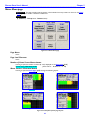
HEADPHONE MIX PAGE ............................................................................................................................................................................. 75
Page Notes................................................................................................................................................................................................................... 76
Page Level Shortcuts.................................................................................................................................................................................................. 76
Preset Loaded Name field ....................................................................................................................................................................................... 76
Disk Tracks matrix buttons ..................................................................................................................................................................................... 76
Outputs matrix buttons ............................................................................................................................................................................................ 76
Camera Returns matrix buttons ............................................................................................................................................................................ 76
(Disk Tracks / Outputs / Camera Returns) Toggle button ............................................................................................................................. 76
Factory Presets button .............................................................................................................................................................................................. 76
User Presets button ................................................................................................................................................................................................... 76
Toggle On Recorded Tracks button ...................................................................................................................................................................... 77
Phase Invert button ................................................................................................................................................................................................... 77
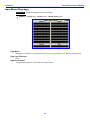
FACTORY PRESETS PAGE ............................................................................................................................................................................ 78
Page Notes................................................................................................................................................................................................................... 78
Page Level Shortcuts.................................................................................................................................................................................................. 78
Preset (#) buttons ...................................................................................................................................................................................................... 78
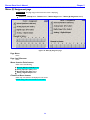
(LOAD / SAVE) USER PRESETS PAGE .......................................................................................................................................................... 79
Page Notes................................................................................................................................................................................................................... 79
Page Level Shortcuts.................................................................................................................................................................................................. 79
Preset (#) buttons ...................................................................................................................................................................................................... 79
Load/Save Toggle button.......................................................................................................................................................................................... 79
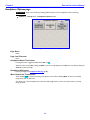
TIME/DATE PAGE ........................................................................................................................................................................................ 80
Page Notes................................................................................................................................................................................................................... 80
Page Level Shortcuts.................................................................................................................................................................................................. 80
Time field ..................................................................................................................................................................................................................... 80
Date field...................................................................................................................................................................................................................... 80
Set Time button .......................................................................................................................................................................................................... 80
Set Time button Shortcuts ................................................................................................................................................................................... 80
Set Date button .......................................................................................................................................................................................................... 80
Set Date button Shortcuts ................................................................................................................................................................................... 80
Time mode button ..................................................................................................................................................................................................... 81
Date mode button ..................................................................................................................................................................................................... 81
Daylight Savings Time button ................................................................................................................................................................................. 81
MEMORY PAGE............................................................................................................................................................................................ 82
Page Notes................................................................................................................................................................................................................... 82
Page Level Shortcuts.................................................................................................................................................................................................. 82
Restore Factory Defaults button ............................................................................................................................................................................ 82
MIX12 SETUP PAGE .................................................................................................................................................................................... 83
Page Notes................................................................................................................................................................................................................... 83
Page Level Shortcuts.................................................................................................................................................................................................. 83
Mix-12 Support button............................................................................................................................................................................................. 83
Meter Brightness button .......................................................................................................................................................................................... 83
Tone Button Assign button ...................................................................................................................................................................................... 83
Fader Channel Assignment button ........................................................................................................................................................................ 83
ZAXNET SETUP PAGE ................................................................................................................................................................................ 84
Page Notes................................................................................................................................................................................................................... 84
Page Level Shortcuts.................................................................................................................................................................................................. 84
ZaxNet Enable button .............................................................................................................................................................................................. 84
Transport Slaved button........................................................................................................................................................................................... 84
Power Roll button ....................................................................................................................................................................................................... 84
USER INTERFACE SETTINGS PAGE ............................................................................................................................................................. 85
7
_________________________________________________________Zaxcom Deva User’s Manual
Page Notes................................................................................................................................................................................................................... 85
Page Level Shortcuts.................................................................................................................................................................................................. 85
Start-Up Screen button ............................................................................................................................................................................................ 85
Hold Key Time button .............................................................................................................................................................................................. 85
False Start button....................................................................................................................................................................................................... 85
Default STN Edit Position button .......................................................................................................................................................................... 85
Color Theme button .................................................................................................................................................................................................. 86
Big STN button ........................................................................................................................................................................................................... 86
Backlight Brightness button ..................................................................................................................................................................................... 86
Location button ........................................................................................................................................................................................................... 86
INPUT CONFIGURE PAGE (ANALOG INPUTS SELECTED) ......................................................................................................................... 87
Page Notes................................................................................................................................................................................................................... 87
Page Level Shortcuts.................................................................................................................................................................................................. 87
Analog (#) buttons ..................................................................................................................................................................................................... 87
(Analog / Digital / Line Lvl) Inputs Toggle button.............................................................................................................................................. 87
High Pass Filter button ............................................................................................................................................................................................. 87
Enabling the Highpass Filter ................................................................................................................................................................................. 87
Mic/Line Level button ................................................................................................................................................................................................ 88
Clear All button ........................................................................................................................................................................................................... 88
Adjust Delay button ................................................................................................................................................................................................... 88
High Pass (#) Hz button ......................................................................................................................................................................................... 88
High Pass (#) Hz button Shortcuts .................................................................................................................................................................... 88
Adjust Trim button ..................................................................................................................................................................................................... 88
ANALOG INPUT (#) PAGE ......................................................................................................................................................................... 89
Page Notes................................................................................................................................................................................................................... 89
Page Level Shortcuts.................................................................................................................................................................................................. 89
(Mic / Line) Level button .......................................................................................................................................................................................... 89
48V (On / Off) button .............................................................................................................................................................................................. 89
Setting Phantom Power ........................................................................................................................................................................................ 89
Delay button ................................................................................................................................................................................................................ 89
Delay button Shortcuts......................................................................................................................................................................................... 89
HPF button................................................................................................................................................................................................................... 90
HPF button Shortcuts ........................................................................................................................................................................................... 90
Limiter (On / Off) button ......................................................................................................................................................................................... 90
Trimmer graphic fader ............................................................................................................................................................................................. 90
Level meter .................................................................................................................................................................................................................. 90
Digital Output button ................................................................................................................................................................................................ 90
Dynamics button ........................................................................................................................................................................................................ 90
EQ button..................................................................................................................................................................................................................... 90
BUS button .................................................................................................................................................................................................................. 90
Mix12 Input Trim Select button ............................................................................................................................................................................ 90
ANALOG INPUT (#) – DYNAMICS PAGE .................................................................................................................................................. 91
Page Notes................................................................................................................................................................................................................... 91
Page Level Shortcuts.................................................................................................................................................................................................. 91
Level meter .................................................................................................................................................................................................................. 91
Gain meter ................................................................................................................................................................................................................... 91
Compress (On / Off) button.................................................................................................................................................................................... 91
Attack button .............................................................................................................................................................................................................. 91
Attack button Shortcuts ....................................................................................................................................................................................... 91
Decay button ............................................................................................................................................................................................................... 92
Decay button Shortcuts........................................................................................................................................................................................ 92
Thresh button .............................................................................................................................................................................................................. 92
Thresh button Shortcuts ...................................................................................................................................................................................... 92
Ratio button ................................................................................................................................................................................................................. 92
Ratio button Shortcuts ......................................................................................................................................................................................... 92
Gain button .................................................................................................................................................................................................................. 92
Gain button Shortcuts........................................................................................................................................................................................... 92
Copy Compress button ............................................................................................................................................................................................. 92
Inc button ..................................................................................................................................................................................................................... 92
Dec button ................................................................................................................................................................................................................... 93
8
Zaxcom Deva User’s Manual_________________________________________________________
ANALOG INPUT (#) – EQ PAGE ............................................................................................................................................................... 94
Page Notes................................................................................................................................................................................................................... 94
EQ page Level Shortcuts .......................................................................................................................................................................................... 94
EQ Memory view Shortcuts..................................................................................................................................................................................... 95
(Band / Notch) (#) field ........................................................................................................................................................................................... 95
Level field...................................................................................................................................................................................................................... 95
Level field Shortcuts .............................................................................................................................................................................................. 95
(BYPASSED / INLINE) flag ...................................................................................................................................................................................... 95
Band Type flag ............................................................................................................................................................................................................ 95
Freq field ....................................................................................................................................................................................................................... 95
Freq field Shortcuts ............................................................................................................................................................................................... 95
Q field............................................................................................................................................................................................................................ 95
Q field Shortcuts .................................................................................................................................................................................................... 95
Equalization graph..................................................................................................................................................................................................... 95
Band (#) buttons ........................................................................................................................................................................................................ 96
Notch (#) buttons ...................................................................................................................................................................................................... 96
Entry Mode button .................................................................................................................................................................................................... 96
ANALOG INPUT (#) – BUS PAGE ............................................................................................................................................................. 97
Page Notes................................................................................................................................................................................................................... 97
Page Level Shortcuts.................................................................................................................................................................................................. 97
Disk Channel (#) buttons ........................................................................................................................................................................................ 97
Output Channel (#) buttons ................................................................................................................................................................................... 97
INPUT CONFIGURE PAGE (DIGITAL INPUTS SELECTED) .......................................................................................................................... 98
Page Notes................................................................................................................................................................................................................... 98
Page Level Shortcuts.................................................................................................................................................................................................. 98
Digital (#) buttons ..................................................................................................................................................................................................... 98
(Analog / Digital / Line Lvl) Inputs Toggle button.............................................................................................................................................. 98
High Pass Filter button ............................................................................................................................................................................................. 98
Enabling the Highpass Filter ................................................................................................................................................................................. 98
Clear All button ........................................................................................................................................................................................................... 98
Adjust Delay button ................................................................................................................................................................................................... 99
High Pass (#) Hz button ......................................................................................................................................................................................... 99
High Pass button Shortcuts.................................................................................................................................................................................. 99
Adjust Trim button ..................................................................................................................................................................................................... 99
DIGITAL INPUT (#) PAGE ......................................................................................................................................................................... 100
Page Notes................................................................................................................................................................................................................. 100
Page Level Shortcuts................................................................................................................................................................................................ 100
Delay button .............................................................................................................................................................................................................. 100
Delay button Shortcuts....................................................................................................................................................................................... 100
HPF button................................................................................................................................................................................................................. 100
HPF button Shortcuts ......................................................................................................................................................................................... 100
Trimmer graphic fader ........................................................................................................................................................................................... 100
Level meter ................................................................................................................................................................................................................ 101
Dynamics button ...................................................................................................................................................................................................... 101
EQ button................................................................................................................................................................................................................... 101
BUS button ................................................................................................................................................................................................................ 101
Mix12 Input Trim Select button .......................................................................................................................................................................... 101
DIGITAL INPUT (#) – DYNAMICS PAGE .................................................................................................................................................. 102
Page Notes................................................................................................................................................................................................................. 102
Page Level Shortcuts................................................................................................................................................................................................ 102
Level meter ................................................................................................................................................................................................................ 102
Gain meter ................................................................................................................................................................................................................. 102
Compress (On / Off) button.................................................................................................................................................................................. 102
Attack button ............................................................................................................................................................................................................ 102
Attack button Shortcuts ..................................................................................................................................................................................... 102
Decay button ............................................................................................................................................................................................................. 102
Decay button Shortcuts...................................................................................................................................................................................... 103
Thresh button ............................................................................................................................................................................................................ 103
Thresh button Shortcuts .................................................................................................................................................................................... 103
Ratio button ............................................................................................................................................................................................................... 103
9
_________________________________________________________Zaxcom Deva User’s Manual
Ratio button Shortcuts ....................................................................................................................................................................................... 103
Gain button ................................................................................................................................................................................................................ 103
Gain button Shortcuts......................................................................................................................................................................................... 103
Copy Compress button ........................................................................................................................................................................................... 103
Inc button ................................................................................................................................................................................................................... 103
Dec button ................................................................................................................................................................................................................. 103
DIGITAL INPUT (#) – EQ PAGE............................................................................................................................................................... 104
Page Notes................................................................................................................................................................................................................. 104
EQ page Level Shortcuts ........................................................................................................................................................................................ 104
EQ Memory view Shortcuts................................................................................................................................................................................... 105
(Band / Notch) (#) field ......................................................................................................................................................................................... 105
Level field.................................................................................................................................................................................................................... 105
Level field Shortcuts ............................................................................................................................................................................................ 105
(BYPASSED / INLINE) flag .................................................................................................................................................................................... 105
Band Type flag .......................................................................................................................................................................................................... 105
Freq field ..................................................................................................................................................................................................................... 105
Freq field Shortcuts ............................................................................................................................................................................................. 105
Q field.......................................................................................................................................................................................................................... 105
Q field Shortcuts .................................................................................................................................................................................................. 105
Equalization graph................................................................................................................................................................................................... 105
Band (#) buttons ...................................................................................................................................................................................................... 105
Notch (#) buttons .................................................................................................................................................................................................... 106
Entry Mode button .................................................................................................................................................................................................. 106
DIGITAL INPUT (#) – BUS PAGE ............................................................................................................................................................. 107
Page Notes................................................................................................................................................................................................................. 107
Page Level Shortcuts................................................................................................................................................................................................ 107
Disk Channel (#) buttons ...................................................................................................................................................................................... 107
Output Channel (#) buttons ................................................................................................................................................................................. 107
INPUT CONFIGURE PAGE (LINE LVL INPUTS SELECTED) (DEVA-16 ONLY) ........................................................................................ 108
Page Notes................................................................................................................................................................................................................. 108
Page Level Shortcuts................................................................................................................................................................................................ 108
Line Level Channel buttons ................................................................................................................................................................................... 108
(Analog / Digital / Line Lvl) Inputs Toggle button............................................................................................................................................ 108
Route Line Lvl Input button ................................................................................................................................................................................... 108
Clear All button ......................................................................................................................................................................................................... 108
(ANALOG / DIGITAL) INPUT DELAY PAGE ............................................................................................................................................. 109
Page Notes................................................................................................................................................................................................................. 109
Page Level Shortcuts................................................................................................................................................................................................ 109
Channel (#) buttons ................................................................................................................................................................................................ 109
More Delay button .................................................................................................................................................................................................. 109
Less Delay button..................................................................................................................................................................................................... 109
Enter Delay button .................................................................................................................................................................................................. 109
Enter Delay button Shortcuts ........................................................................................................................................................................... 109
Clear Delay button .................................................................................................................................................................................................. 109
Delay Mode button ................................................................................................................................................................................................. 110
Adjusting the Delay.................................................................................................................................................................................................. 110
(ANALOG / DIGITAL) INPUT TRIM PAGE ................................................................................................................................................ 111
Page Notes................................................................................................................................................................................................................. 111
Page Level Shortcuts................................................................................................................................................................................................ 111
Input (#) Trim fields ................................................................................................................................................................................................ 111
Input (#) Level meters ............................................................................................................................................................................................ 111
Less Gain button....................................................................................................................................................................................................... 111
More Gain button .................................................................................................................................................................................................... 111
Clear Trim button .................................................................................................................................................................................................... 111
Select All button........................................................................................................................................................................................................ 111
Adjusting the Trim.................................................................................................................................................................................................... 111
MY DEVA PAGE......................................................................................................................................................................................... 112
Page Notes................................................................................................................................................................................................................. 112
Page Level Shortcuts................................................................................................................................................................................................ 112
10
Zaxcom Deva User’s Manual_________________________________________________________
Internal HD drive button ....................................................................................................................................................................................... 112
Internal HD drive Status button .......................................................................................................................................................................... 112
Mirror Drive button ................................................................................................................................................................................................. 112
Mirror Drive Status button .................................................................................................................................................................................... 112
Mirror Drive Select button..................................................................................................................................................................................... 112
Firewire Power button ............................................................................................................................................................................................. 112
INTERNAL DISK UTILITIES PAGE .............................................................................................................................................................. 113
Page Notes................................................................................................................................................................................................................. 113
Page Level Shortcuts................................................................................................................................................................................................ 113
Erase Current Folder button ................................................................................................................................................................................. 113
Current Folder button ............................................................................................................................................................................................. 113
Delete Last Segment button ................................................................................................................................................................................. 113
Format Drive button ................................................................................................................................................................................................ 113
DISK FOLDERS PAGE................................................................................................................................................................................. 114
Page Notes................................................................................................................................................................................................................. 114
Page Level Shortcuts................................................................................................................................................................................................ 114
Folder buttons ........................................................................................................................................................................................................... 114
Up Arrow button ...................................................................................................................................................................................................... 114
Sort Order button..................................................................................................................................................................................................... 114
Page Up button ........................................................................................................................................................................................................ 114
Enable Mirror Playback button ............................................................................................................................................................................ 114
Page Down button ................................................................................................................................................................................................... 115
Name Folder button ................................................................................................................................................................................................ 115
Name Folder button Shortcuts ......................................................................................................................................................................... 115
Down Arrow button ................................................................................................................................................................................................. 115
Erase Folder button ................................................................................................................................................................................................. 115
FOLDER “???” CONTENTS PAGE.............................................................................................................................................................. 116
Page Notes................................................................................................................................................................................................................. 116
Page Level Shortcuts................................................................................................................................................................................................ 116
#:# Segs field ............................................................................................................................................................................................................ 116
Take buttons ............................................................................................................................................................................................................. 116
Up Arrow button ...................................................................................................................................................................................................... 116
Page Up button ........................................................................................................................................................................................................ 116
Enter Seg # button .................................................................................................................................................................................................. 116
Enter Seg # button Shortcuts ............................................................................................................................................................................ 116
Page Down button ................................................................................................................................................................................................... 116
Edit STN (Scene, Take, Note) button ................................................................................................................................................................ 116
Down Arrow button ................................................................................................................................................................................................. 117
FORMAT MENU WARNING PAGE ........................................................................................................................................................... 118
Page Notes................................................................................................................................................................................................................. 118
Page Level Shortcuts................................................................................................................................................................................................ 118
Format Drive button ................................................................................................................................................................................................ 118
Do Not Format Drive button ................................................................................................................................................................................ 118
FORMATTING DIALOG BOX..................................................................................................................................................................... 119
Page Notes................................................................................................................................................................................................................. 119
Page Level Shortcuts................................................................................................................................................................................................ 119
MIRROR DRIVE PAGE ................................................................................................................................................................................ 120
Page Notes................................................................................................................................................................................................................. 120
Page Level Shortcuts................................................................................................................................................................................................ 120
Segment number data entry field........................................................................................................................................................................ 120
Segment number data entry field Shortcuts ................................................................................................................................................... 120
File Type button ........................................................................................................................................................................................................ 120
File Resolution button.............................................................................................................................................................................................. 120
Format Drive button ................................................................................................................................................................................................ 120
Tracks to Mirror button ......................................................................................................................................................................................... 120
Folder to Mirror button........................................................................................................................................................................................... 121
Start Seg button ....................................................................................................................................................................................................... 121
End Seg button ......................................................................................................................................................................................................... 121
Mirror Mode button ................................................................................................................................................................................................ 121
11
_________________________________________________________Zaxcom Deva User’s Manual
Advanced Options button ...................................................................................................................................................................................... 121
Mirror Drive Status button .................................................................................................................................................................................... 121
MIRROR FILE TYPE PAGE .......................................................................................................................................................................... 122
Page Notes................................................................................................................................................................................................................. 122
Page Level Shortcuts................................................................................................................................................................................................ 122
File Type buttons ...................................................................................................................................................................................................... 122
Pull Up / Down buttons .......................................................................................................................................................................................... 122
FORMAT MIRROR DRIVE CAUTION PAGE .............................................................................................................................................. 123
Page Notes................................................................................................................................................................................................................. 123
Page Level Shortcuts................................................................................................................................................................................................ 123
Format Drive FAT32 button .................................................................................................................................................................................. 123
Do Not Format Drive button ................................................................................................................................................................................ 123
TRACKS TO MIRROR PAGE ...................................................................................................................................................................... 124
Page Notes................................................................................................................................................................................................................. 124
Page Level Shortcuts................................................................................................................................................................................................ 124
Tracks to Mirror buttons........................................................................................................................................................................................ 124
MIRROR FOLDERS PAGE ........................................................................................................................................................................... 125
Page Notes................................................................................................................................................................................................................. 125
Page Level Shortcuts................................................................................................................................................................................................ 125
Folder buttons ........................................................................................................................................................................................................... 125
Up Arrow button ...................................................................................................................................................................................................... 125
Sort Order button..................................................................................................................................................................................................... 125
Page Up button ........................................................................................................................................................................................................ 125
Page Down button ................................................................................................................................................................................................... 125
Mirroring Mode button........................................................................................................................................................................................... 125
Down Arrow button ................................................................................................................................................................................................. 125
ADVANCED MIRROR OPTIONS PAGE ..................................................................................................................................................... 126
Page Notes................................................................................................................................................................................................................. 126
Page Level Shortcuts................................................................................................................................................................................................ 126
Timecode Offset button ......................................................................................................................................................................................... 126
Write Sound Report button................................................................................................................................................................................... 126
CUE MODE PAGE ..................................................................................................................................................................................... 127
Page Notes................................................................................................................................................................................................................. 127
Page Level Shortcuts................................................................................................................................................................................................ 127
Enter Segment data entry field ............................................................................................................................................................................ 127
Enter Segment data entry field Shortcuts ....................................................................................................................................................... 127
Mode Status button................................................................................................................................................................................................. 127
View button ................................................................................................................................................................................................................ 128
Timecode button ...................................................................................................................................................................................................... 128
Disk icon ..................................................................................................................................................................................................................... 128
Remaining Recording Time field .......................................................................................................................................................................... 128
Battery icon button .................................................................................................................................................................................................. 128
Prev Seg button......................................................................................................................................................................................................... 128
Next Seg button ....................................................................................................................................................................................................... 128
Enter Seg button ...................................................................................................................................................................................................... 128
<< REW button ....................................................................................................................................................................................................... 128
>> FFWD button ..................................................................................................................................................................................................... 129
Cue Toggle button ................................................................................................................................................................................................... 129
Set ZaxNet UB button ........................................................................................................................................................................................... 129
Wireless ReRec button ........................................................................................................................................................................................... 129
Wireless Audition button ........................................................................................................................................................................................ 129
Cur Segs Folder button ........................................................................................................................................................................................... 129
Cur field.................................................................................................................................................................................................................. 129
Segs field ................................................................................................................................................................................................................. 129
Folder field ............................................................................................................................................................................................................. 129
S: T: N: button........................................................................................................................................................................................................ 129
Input (#) meters & buttons .................................................................................................................................................................................. 129
Arm / Disarm a Recording Track ..................................................................................................................................................................... 130
SCENE TAKE NOTE PAGE ........................................................................................................................................................................ 131
12
Zaxcom Deva User’s Manual_________________________________________________________
Page Notes................................................................................................................................................................................................................. 131
Page Level Shortcuts................................................................................................................................................................................................ 131
Enter Segment data entry field ............................................................................................................................................................................ 131
Enter Segment data entry field Shortcuts ....................................................................................................................................................... 131
#:# Segs field ............................................................................................................................................................................................................ 132
Scene button ............................................................................................................................................................................................................. 132
Scene button Shortcuts ...................................................................................................................................................................................... 132
Inc Scene button....................................................................................................................................................................................................... 132
Take button ............................................................................................................................................................................................................... 132
Take button Shortcuts ........................................................................................................................................................................................ 132
Reset Take button ................................................................................................................................................................................................... 132
Note button ............................................................................................................................................................................................................... 132
Note button Shortcuts ....................................................................................................................................................................................... 132
Store Note button .................................................................................................................................................................................................... 132
Clear Note button .................................................................................................................................................................................................... 132
Segment button ........................................................................................................................................................................................................ 132
Segment button Shortcuts ................................................................................................................................................................................. 132
Left Arrow button ..................................................................................................................................................................................................... 132
Right Arrow button .................................................................................................................................................................................................. 132
Stored Note buttons ................................................................................................................................................................................................ 132
Up Arrow button ...................................................................................................................................................................................................... 133
Down Arrow button ................................................................................................................................................................................................. 133
ABOUT DEVA PAGE.................................................................................................................................................................................. 134
Page Notes................................................................................................................................................................................................................. 134
Page Level Shortcuts................................................................................................................................................................................................ 134
KEYBOARD PAGE ...................................................................................................................................................................................... 135
Page Notes................................................................................................................................................................................................................. 135
Page Level Shortcuts................................................................................................................................................................................................ 135
Bsp button .................................................................................................................................................................................................................. 135
Ent button (Enter) .................................................................................................................................................................................................... 135
Shift button ................................................................................................................................................................................................................ 135
Caps button ............................................................................................................................................................................................................... 135
Left Arrow button ..................................................................................................................................................................................................... 135
Right Arrow button .................................................................................................................................................................................................. 136
BATTERY MENU PAGE .............................................................................................................................................................................. 137
Page Notes................................................................................................................................................................................................................. 137
Page Level Shortcuts................................................................................................................................................................................................ 137
Low Battery Voltage button ................................................................................................................................................................................... 137
Low Battery Voltage button Shortcuts ........................................................................................................................................................... 137
Reset Graph button ................................................................................................................................................................................................. 137
Battery Type field ..................................................................................................................................................................................................... 137
Voltage field ............................................................................................................................................................................................................... 137
Voltage vs. Time graph ........................................................................................................................................................................................... 137
HEADPHONE VOLUME PAGE ................................................................................................................................................................... 138
Page Notes................................................................................................................................................................................................................. 138
Page Level Shortcuts................................................................................................................................................................................................ 138
Headphone Linear graphic fader ........................................................................................................................................................................ 138
FALSE START DIALOG............................................................................................................................................................................... 139
Page Notes................................................................................................................................................................................................................. 139
Page Level Shortcuts................................................................................................................................................................................................ 139
Folder field ................................................................................................................................................................................................................. 139
Segment field ............................................................................................................................................................................................................ 139
Duration field ............................................................................................................................................................................................................ 139
Scene field .................................................................................................................................................................................................................. 139
Take field ................................................................................................................................................................................................................... 139
Mark it button .......................................................................................................................................................................................................... 139
Cancel button ............................................................................................................................................................................................................ 139
Delete it button ........................................................................................................................................................................................................ 139
DEVA SERVICE MENU WARNING PAGE.................................................................................................................................................. 140
13
_________________________________________________________Zaxcom Deva User’s Manual
Page Notes................................................................................................................................................................................................................. 140
Page Level Shortcuts................................................................................................................................................................................................ 140
Software Options button ........................................................................................................................................................................................ 140
Processor Speed button .......................................................................................................................................................................................... 140
Load ProgFile button................................................................................................................................................................................................ 140
Load From CD-R button ......................................................................................................................................................................................... 140
Burn Program ROM button ................................................................................................................................................................................... 140
DEBUG SCREEN DIALOG BOX ................................................................................................................................................................. 141
Page Notes................................................................................................................................................................................................................. 141
Page Level Shortcuts................................................................................................................................................................................................ 141
*B AND *P DIAGNOSTIC FLAGS ............................................................................................................................................................. 142
*B Flag ........................................................................................................................................................................................................................ 142
*P Flag......................................................................................................................................................................................................................... 142
CHAPTER 4 – SETTING UP THE POWER AND AUDIO CONNECTIONS .............................................. 143
POWER ...................................................................................................................................................................................................... 143
Internal Power ........................................................................................................................................................................................................... 143
External Power .......................................................................................................................................................................................................... 143
Battery Display.......................................................................................................................................................................................................... 143
Battery Chemistry ................................................................................................................................................................................................ 143
Setting the Battery Threshold ............................................................................................................................................................................... 143
TIME AND DATE ....................................................................................................................................................................................... 144
ANALOG / DIGITAL AUDIO INPUTS ....................................................................................................................................................... 144
Switching Between Mic- and Line-Level Input (Analog Only)...................................................................................................................... 145
Enabling the High Pass Filter (Analog / Digital) ............................................................................................................................................. 145
Setting the High Pass Filter value ...................................................................................................................................................................... 145
Setting the High Pass Filter Frequency on Multiple Channels .................................................................................................................... 145
Enabling 48 VDC Phantom Power (Analog Only) .......................................................................................................................................... 145
Adjusting the Trim (Analog / Digital) ................................................................................................................................................................. 145
Adjusting the Trim using the Analog / Digital Input Trim page ................................................................................................................. 145
Adjusting Individual Trim Levels Using the Input (#) page ......................................................................................................................... 146
Adjusting the Delay (Analog / Digital) ............................................................................................................................................................... 146
Adjusting the Delay Using the Input Delay page ........................................................................................................................................... 146
Adjusting the Delay Using the Input (#) page ................................................................................................................................................ 146
ANALOG AUDIO OUTPUTS .................................................................................................................................................................... 146
DIGITAL AUDIO OUTPUTS ...................................................................................................................................................................... 147
CAMERA / LINE IN CONNECTOR............................................................................................................................................................ 147
Deva-5.8 ..................................................................................................................................................................................................................... 147
Deva-16 ...................................................................................................................................................................................................................... 147
Configuring Analog Inputs 9 – 12 (Deva-16 only) ........................................................................................................................................ 147
ASSIGNING INPUTS TO RECORDING TRACKS AND OUTPUTS ............................................................................................................. 148
Assigning Inputs to Recording Tracks ................................................................................................................................................................. 148
Setting the Number of Tracks Recorded ........................................................................................................................................................... 148
Set the Sampling-rate for Recorded Tracks ...................................................................................................................................................... 148
Assign Inputs to Output Channels ....................................................................................................................................................................... 148
OVERVIEW OF INPUT SIGNALS ................................................................................................................................................................ 149
OVERVIEW OF OUTPUT SIGNALS ........................................................................................................................................................... 149
CHAPTER 5 – SETTINGS FOR RECORDING ................................................................................................. 150
STORING THE DATA ................................................................................................................................................................................ 150
Selecting a folder ...................................................................................................................................................................................................... 150
SETTING THE PRE-RECORD DURATION ................................................................................................................................................. 150
SET THE TONE LEVEL AND DESTINATIONS ........................................................................................................................................... 150
Set the Tone output ................................................................................................................................................................................................ 150
Enable the Tone ....................................................................................................................................................................................................... 150
HOME PAGE METERS ................................................................................................................................................................................ 150
Set the Number of Meters .................................................................................................................................................................................... 151
Set the Meter Labels ............................................................................................................................................................................................... 151
Change the Meter’s Appearance ......................................................................................................................................................................... 151
Change the Meter Orientation ......................................................................................................................................................................... 151
14
Zaxcom Deva User’s Manual_________________________________________________________
Meter Color Schemes ......................................................................................................................................................................................... 151
Screen Backlight Brightness .................................................................................................................................................................................. 151
MONITORING WITH HEADPHONES ....................................................................................................................................................... 151
Fader #8..................................................................................................................................................................................................................... 151
Load a Factory Preset ............................................................................................................................................................................................. 152
Build Your Own Headphone Mix (Working Preset) ....................................................................................................................................... 152
Invert Phase ........................................................................................................................................................................................................... 152
Retaining Your Headphone Mix with a User Preset ...................................................................................................................................... 152
Storing the Mix in a User Preset ...................................................................................................................................................................... 152
Loading a Mix Saved in a User Preset.............................................................................................................................................................. 152
Camera Input (Deva-5.8 only) ............................................................................................................................................................................ 152
TIMECODE PAGE ....................................................................................................................................................................................... 154
Timecode Displayed on the Home page ........................................................................................................................................................... 154
Timecode Output ..................................................................................................................................................................................................... 154
Entering User-bit Data ........................................................................................................................................................................................... 154
Entering Timecode ................................................................................................................................................................................................... 154
Frame-rate ................................................................................................................................................................................................................. 154
CHAPTER 6 – USING ZAXNET ........................................................................................................................ 155
ZAXNET SETUP ........................................................................................................................................................................................ 155
ZAXNET ENABLE ...................................................................................................................................................................................... 155
SLAVED / NON-SLAVED OPERATION ...................................................................................................................................................... 155
TRANSMITTER GAIN SETUP ...................................................................................................................................................................... 155
WIRELESS AUDITION & WIRELESS RE-RECORD .................................................................................................................................... 156
CHAPTER 7 – NEW SYSTEM CAPABILITIES ................................................................................................ 157
INTRODUCTION ....................................................................................................................................................................................... 157
IMPROVEMENTS......................................................................................................................................................................................... 157
Power Roll feature.................................................................................................................................................................................................... 157
Folder Recovery function ........................................................................................................................................................................................ 157
New Processor Speed Selection feature ............................................................................................................................................................ 157
Saving and restoring Deva's configuration INI files ........................................................................................................................................ 157
Simultaneous Mirror feature ................................................................................................................................................................................. 158
“Mirror All Folders” feature .................................................................................................................................................................................. 158
KNOWN FIRMWARE ISSUES ..................................................................................................................................................................... 158
CHAPTER 8 – SHORTCUT KEYS ..................................................................................................................... 159
COMMON DATA ENTRY FIELD SHORTCUTS LIST ................................................................................................................................. 159
Keyboard Keys .......................................................................................................................................................................................................... 159
Front Panel Keys ....................................................................................................................................................................................................... 159
COMMON KEYBOARD PAGE SHORTCUTS LIST ..................................................................................................................................... 159
FRONT PANEL SHORTCUTS .................................................................................................................................................................... 159
MIX-12 EMBEDDED KEYBOARD SHORTCUTS ........................................................................................................................................ 160
ATTACHED KEYBOARD SHORTCUTS ..................................................................................................................................................... 160
BOOT-UP SHORTCUTS ............................................................................................................................................................................ 161
Page Level Shortcuts................................................................................................................................................................................................ 161
Boot Keys ................................................................................................................................................................................................................... 161
HOME PAGE SHORTCUTS ........................................................................................................................................................................ 161
Using the Deva front panel: .................................................................................................................................................................................. 161
Using the Mix-12 embedded keyboard: ............................................................................................................................................................ 162
Using an attached keyboard: ................................................................................................................................................................................ 162
DISK LIMITER SETTINGS PAGE SHORTCUTS............................................................................................................................................ 163
OUTPUT LIMITER SETTINGS PAGE SHORTCUTS ..................................................................................................................................... 163
Attack button Shortcuts.......................................................................................................................................................................................... 163
Decay button Shortcuts .......................................................................................................................................................................................... 163
Thresh button Shortcuts ......................................................................................................................................................................................... 163
Ratio button Shortcuts ............................................................................................................................................................................................ 163
Gain button Shortcuts ............................................................................................................................................................................................. 163
TIMECODE PAGE SHORTCUTS ................................................................................................................................................................. 163
15
_________________________________________________________Zaxcom Deva User’s Manual
Enter Timecode button Shortcuts ........................................................................................................................................................................ 163
Enter User Bits button Shortcuts ......................................................................................................................................................................... 164
METER LABELS PAGE SHORTCUTS ........................................................................................................................................................... 164
Meter (#) Label buttons Shortcuts...................................................................................................................................................................... 164
TIME/DATE PAGE SHORTCUTS ................................................................................................................................................................ 164
Set Time button Shortcuts ..................................................................................................................................................................................... 164
Set Date button Shortcuts ..................................................................................................................................................................................... 164
INPUT CONFIGURE PAGE SHORTCUTS ................................................................................................................................................... 164
High Pass (#) Hz button Shortcuts..................................................................................................................................................................... 164
(ANALOG / DIGITAL / LINELVL) INPUT (#) PAGE SHORTCUTS ............................................................................................................ 164
Delay button Shortcuts ........................................................................................................................................................................................... 164
HPF button Shortcuts .............................................................................................................................................................................................. 164
(ANALOG / DIGITAL) INPUT (#) – DYNAMICS PAGE SHORTCUTS ...................................................................................................... 164
Attack button Shortcuts.......................................................................................................................................................................................... 164
Decay button Shortcuts .......................................................................................................................................................................................... 164
Thresh button Shortcuts ......................................................................................................................................................................................... 165
Ratio button Shortcuts ............................................................................................................................................................................................ 165
Gain button Shortcuts ............................................................................................................................................................................................. 165
(ANALOG / DIGITAL) INPUT (#) – EQ PAGE SHORTCUTS ................................................................................................................... 165
Level field Shortcuts ................................................................................................................................................................................................. 165
Freq field Shortcuts .................................................................................................................................................................................................. 166
Q field Shortcuts ....................................................................................................................................................................................................... 166
EQ Memory view Shortcuts................................................................................................................................................................................... 166
(ANALOG / DIGITAL) INPUT (#) – BUS PAGE SHORTCUTS ................................................................................................................. 166
(ANALOG / DIGITAL) INPUT DELAY PAGE SHORTCUTS ....................................................................................................................... 166
Enter Delay button Shortcuts ............................................................................................................................................................................... 166
DISK FOLDERS PAGE SHORTCUTS........................................................................................................................................................... 166
Name Folder button Shortcuts ............................................................................................................................................................................. 166
FOLDER “???” CONTENTS PAGE SHORTCUTS........................................................................................................................................ 166
Enter Seg # button Shortcuts ............................................................................................................................................................................... 166
MIRROR DRIVE PAGE SHORTCUTS .......................................................................................................................................................... 166
Start Seg field Shortcuts ......................................................................................................................................................................................... 166
End Seg field Shortcuts........................................................................................................................................................................................... 166
CUE MODE PAGE SHORTCUTS................................................................................................................................................................ 167
Enter Segment data entry field Shortcuts ......................................................................................................................................................... 167
SCENE TAKE NOTE PAGE SHORTCUTS .................................................................................................................................................. 167
Enter Segment data entry field Shortcuts ......................................................................................................................................................... 167
Scene button Shortcuts........................................................................................................................................................................................... 167
Take button Shortcuts ............................................................................................................................................................................................ 167
Note button Shortcuts ............................................................................................................................................................................................ 167
Segment button Shortcuts ..................................................................................................................................................................................... 167
BATTERY MENU PAGE SHORTCUTS ........................................................................................................................................................ 167
Low Battery Voltage button Shortcuts ................................................................................................................................................................ 167
HEADPHONE VOLUME PAGE SHORTCUTS ............................................................................................................................................. 168
DEBUG SCREEN (1967) PAGE SHORTCUTS ........................................................................................................................................... 168
CHAPTER 9 – EQUIPMENT SPECIFICATIONS ............................................................................................. 169
CHAPTER 10 – CONNECTOR PINOUTS ....................................................................................................... 173
POWER CONNECTOR (XLR-4) ............................................................................................................................................................. 173
HEADPHONE OUTPUT CONNECTOR (1/4” STEREO PLUG) ................................................................................................................. 173
ANALOG INPUT / OUTPUT CONNECTORS (XLR-3) ........................................................................................................................... 174
ANALOG OUTPUT CONNECTOR (DB-25) ........................................................................................................................................... 175
SERIAL/GPI CONNECTOR (DB-9).......................................................................................................................................................... 175
LINE IN / CAMERA CONNECTOR (HIROSE-10) ..................................................................................................................................... 176
Deva-5.8 ..................................................................................................................................................................................................................... 176
Deva-16 ...................................................................................................................................................................................................................... 176
TIMECODE CONNECTOR (LEMO-5) ..................................................................................................................................................... 177
AES DIGITAL INPUT / OUTPUT CONNECTORS (DB-15)..................................................................................................................... 177
16
Zaxcom Deva User’s Manual_________________________________________________________
CHAPTER 11 – FIRMWARE INFORMATION ................................................................................................. 178
FIRMWARE................................................................................................................................................................................................. 178
Advantages to Upgrading the Firmware ............................................................................................................................................................ 178
Upgrading the Firmware in Each Unit ............................................................................................................................................................... 178
FIRMWARE HISTORY ................................................................................................................................................................................ 180
CHAPTER 12 – ZAXCOM WARRANTY POLICY AND LIMITATIONS ..................................................... 183
Table of Figures
FIGURE 2-1 FRONT PANEL IMAGE .................................................................................................................................................................25
FIGURE 2-2 LEFT SIDE IMAGE .........................................................................................................................................................................27
FIGURE 2-3 DEVA-16 & DEVA-5.8 RIGHT SIDE IMAGES ..............................................................................................................................29
FIGURE 3-1 BOOT-UP SEQUENCE PAGE ........................................................................................................................................................30
FIGURE 3-2 HOME PAGE .................................................................................................................................................................................35
FIGURE 3-3 MAIN MENU PAGE ......................................................................................................................................................................40
FIGURE 3-4 DISK MIX PAGE ...........................................................................................................................................................................42
FIGURE 3-5 DISK MIX – LIMITER COLUMN PAGE ..........................................................................................................................................44
FIGURE 3-6 DISK LIMITER SETTINGS PAGE ....................................................................................................................................................45
FIGURE 3-7 OUTPUT MIX PAGE .....................................................................................................................................................................47
FIGURE 3-8 OUTPUT MIX – LIMIT COLUMN PAGE .......................................................................................................................................49
FIGURE 3-9 OUTPUT MIX – OUTPUT ROUTING COLUMNS PAGE..............................................................................................................49
FIGURE 3-10 OUTPUT LIMITER SETTINGS PAGE ...........................................................................................................................................51
FIGURE 3-11 OUTPUT ROUTING PRESETS PAGE ..........................................................................................................................................53
FIGURE 3-12 TOUCH FADER PAGE ................................................................................................................................................................54
FIGURE 3-13 KNOB / TOUCH FADER ASSIGN PAGE ....................................................................................................................................55
FIGURE 3-14 TIMECODE PAGE .......................................................................................................................................................................57
FIGURE 3-15 TIMECODE RUN MODE PAGE ..................................................................................................................................................59
FIGURE 3-16 SETUP PAGE ...............................................................................................................................................................................60
FIGURE 3-17 SAMPLE RATE PAGE ...................................................................................................................................................................62
FIGURE 3-18 RECORD TRACK SELECT PAGE ................................................................................................................................................63
FIGURE 3-19 OPERATING MODE PAGE .........................................................................................................................................................64
FIGURE 3-20 COMMAND MONITOR PAGE ...................................................................................................................................................66
FIGURE 3-21 METER MENU PAGE ..................................................................................................................................................................67
FIGURE 3-22 EXAMPLES OF HOME PAGE LAYOUTS ......................................................................................................................................67
FIGURE 3-23 EFFECTS OF THE COLOR SCHEMES BUTTON ..........................................................................................................................68
FIGURE 3-24 METER LABELS PAGE .................................................................................................................................................................69
FIGURE 3-25 INPUT METER MENU PAGE .......................................................................................................................................................70
FIGURE 3-26 OUTPUT METER MENU PAGE ..................................................................................................................................................71
FIGURE 3-27 METER ASSIGNMENTS PAGE .....................................................................................................................................................72
FIGURE 3-28 METER (#) ASSIGNMENT PAGE ................................................................................................................................................73
FIGURE 3-29 HEADPHONE OPTIONS PAGE ..................................................................................................................................................74
FIGURE 3-30 HEADPHONE MIX PAGE (PART 1) ...........................................................................................................................................75
FIGURE 3-31 HEADPHONE MIX PAGE (PART 2) ...........................................................................................................................................76
FIGURE 3-32 FACTORY PRESETS PAGE ..........................................................................................................................................................78
FIGURE 3-33 (LOAD / SAVE) USER PRESETS PAGE ........................................................................................................................................79
FIGURE 3-34 TIME/DATE PAGE ......................................................................................................................................................................80
FIGURE 3-35 MEMORY PAGE ..........................................................................................................................................................................82
FIGURE 3-36 MIX-12 SETUP PAGE .................................................................................................................................................................83
FIGURE 3-37 ZAXNET SETUP PAGE ...............................................................................................................................................................84
FIGURE 3-38 USER INTERFACE SETTINGS PAGE ............................................................................................................................................85
FIGURE 3-39 EFFECTS OF THE COLOR THEME BUTTON..............................................................................................................................86
FIGURE 3-40 EFFECTS OF THE BIG STN BUTTON ........................................................................................................................................86
FIGURE 3-41 INPUT CONFIGURE PAGE (ANALOG INPUTS SELECTED) .......................................................................................................87
FIGURE 3-42 ANALOG INPUT (#) PAGE ........................................................................................................................................................89
FIGURE 3-43 ANALOG INPUT (#) - DYNAMICS PAGE..................................................................................................................................91
FIGURE 3-44 ANALOG INPUT (#) - EQ PAGE ..............................................................................................................................................94
FIGURE 3-45 ANALOG INPUT (#) - BUS PAGE.............................................................................................................................................97
FIGURE 3-46 INPUT CONFIGURE PAGE (DIGITAL INPUTS SELECTED) .........................................................................................................98
17
_________________________________________________________Zaxcom Deva User’s Manual
FIGURE 3-47
FIGURE 3-48
FIGURE 3-49
FIGURE 3-50
FIGURE 3-51
FIGURE 3-52
FIGURE 3-53
FIGURE 3-54
FIGURE 3-55
FIGURE 3-56
FIGURE 3-57
FIGURE 3-58
FIGURE 3-59
FIGURE 3-60
FIGURE 3-61
FIGURE 3-62
FIGURE 3-63
FIGURE 3-64
FIGURE 3-65
FIGURE 3-66
FIGURE 3-67
FIGURE 3-68
FIGURE 3-69
FIGURE 3-70
FIGURE 3-71
FIGURE 3-72
FIGURE 3-73
FIGURE 3-74
FIGURE 3-75
FIGURE 10-1
FIGURE 10-2
FIGURE 10-3
FIGURE 10-4
FIGURE 10-5
FIGURE 10-6
FIGURE 10-7
FIGURE 10-8
FIGURE 11-1
FIGURE 11-2
DIGITAL INPUT (#) PAGE ...................................................................................................................................................... 100
DIGITAL INPUT (#) - DYNAMICS PAGE ................................................................................................................................ 102
DIGITAL INPUT (#) - EQ PAGE ............................................................................................................................................. 104
DIGITAL INPUT (#) - BUS PAGE ........................................................................................................................................... 107
INPUT CONFIGURE PAGE (LINE LEVEL INPUTS SELECTED) ................................................................................................. 108
(ANALOG / DIGITAL) INPUT DELAY PAGE .......................................................................................................................... 109
(ANALOG / DIGITAL) INPUT TRIM PAGE ............................................................................................................................. 111
MY DEVA PAGE ...................................................................................................................................................................... 112
INTERNAL DISK UTILITIES PAGE............................................................................................................................................ 113
DISK FOLDERS PAGE .............................................................................................................................................................. 114
FOLDER “???” CONTENTS PAGE ........................................................................................................................................... 116
FORMAT MENU WARNING PAGE......................................................................................................................................... 118
FORMATTING DIALOG BOX ON TOP OF FORMAT MENU WARNING PAGE ..................................................................... 119
SCREEN DISPLAY OF THE PRIMARY DRIVE FORMAT PROCESS ............................................................................................ 119
MIRROR DRIVE PAGE ............................................................................................................................................................. 120
MIRROR FILE TYPE PAGE ....................................................................................................................................................... 122
FORMAT MIRROR DRIVE PAGE ............................................................................................................................................. 123
TRACKS TO MIRROR PAGE.................................................................................................................................................... 124
MIRROR FOLDERS PAGE ........................................................................................................................................................ 125
ADVANCED MIRROR OPTIONS PAGE .................................................................................................................................. 126
CUE MODE PAGE ................................................................................................................................................................... 127
SCENE TAKE NOTE PAGE ...................................................................................................................................................... 131
ABOUT DEVA PAGE ............................................................................................................................................................... 134
GENERIC KEYBOARD PAGE ................................................................................................................................................... 135
BATTERY MENU PAGE ........................................................................................................................................................... 137
HEADPHONE VOLUME PAGE................................................................................................................................................. 138
FALSE START DIALOG ON TOP OF HOME PAGE .................................................................................................................. 139
DEVA SERVICE MENU PAGE................................................................................................................................................... 140
DEBUG SCREEN PAGE ............................................................................................................................................................ 141
XLR-4F POWER CONNECTOR PIN NUMBERING .............................................................................................................. 173
HEADPHONE PLUG CONNECTIONS .................................................................................................................................... 173
XLR-3M (LEFT) AND XLR-3F (RIGHT) AUDIO INPUT & OUTPUT CONNECTOR PIN NUMBERING ............................ 174
DB-25M ANALOG OUTPUT CONNECTOR PIN NUMBERING .......................................................................................... 175
MINI DB-9 15M SERIAL/GPI CONNECTOR PIN NUMBERING .......................................................................................... 175
HIROSE-10M LINE IN / CAMERA CONNECTOR PIN NUMBERING .................................................................................... 176
LEMO-5M TIMECODE CONNECTOR PIN NUMBERING .................................................................................................... 177
MINI DB-15M DIGITAL INPUT AND OUTPUT CONNECTORS PIN NUMBERING............................................................. 177
FIRMWARE INSTALL PART 1 .................................................................................................................................................. 179
FIRMWARE INSTALL PART 2 .................................................................................................................................................. 179
Table of Tables
TABLE 3-1 INDEX OF NOMAD PAGES ...........................................................................................................................................................31
TABLE 3-2 DISK ICON COLOR CODE...........................................................................................................................................................37
TABLE 3-3 INDICATOR DESCRIPTIONS .........................................................................................................................................................42
TABLE 3-4 INDICATOR DESCRIPTIONS .........................................................................................................................................................47
TABLE 3-5 INDICATOR DESCRIPTIONS .........................................................................................................................................................56
TABLE 3-6 INDICATOR DESCRIPTIONS .........................................................................................................................................................97
TABLE 3-7 INDICATOR DESCRIPTIONS ...................................................................................................................................................... 107
TABLE 3-8 MIRROR STORAGE MEDIA FORMAT TIME................................................................................................................................ 123
TABLE 3-9 DISK ICON COLOR CODE........................................................................................................................................................ 128
TABLE 10-1 XLR-4F PIN DESCRIPTION..................................................................................................................................................... 173
TABLE 10-2 HEADPHONE PLUG PIN DESCRIPTION .................................................................................................................................. 173
TABLE 10-3 XLR-3 PIN DESCRIPTION ....................................................................................................................................................... 174
TABLE 10-4 DB-25M PIN DESCRIPTION ................................................................................................................................................... 175
TABLE 10-5 MINI DB-9M PIN DESCRIPTION ............................................................................................................................................ 175
TABLE 10-6 HIROSE 10-PIN DESCRIPTION ................................................................................................................................................ 176
TABLE 10-7 LEMO-5M PIN DESCRIPTION................................................................................................................................................ 177
TABLE 10-8 MINI DB-15M PIN DESCRIPTION .......................................................................................................................................... 177
18
Zaxcom Deva User’s Manual_______________________________________________________ Chapter 1
Chapter 1 – Introduction
Overview
The Zaxcom Deva is a high-resolution audio mixer and recorder for reality television surround recording and
ENG. Lightweight and power efficient, it replaces multiple mixers and portable recorders that are currently used
to mix audio for recording to camera via RF link or hardwired cable.
The Deva has an extensive software and hardware history based on the continuous refinement of our location
recording technology.
The functions of mixing, recording and audio effects are seamlessly integrated providing features, functionality and
audio quality unobtainable with separate solutions. Deva's eight mix busses are a perfect match for the new
generation of ENG cameras that record four to eight tracks of audio.
The Deva is ideal for use with Holophone™ and SoundField™ microphones.
This section describes the Deva’s physical features and their location.
User Manual Conventions
Throughout this manual, the following conventions are used:
button
– refers to an on-screen (VIRTUAL) object that represents a parameter that can be changed
and/or viewed.
CF card
– refers to any CompactFlash card that meets the tests outlined in CompactFlash Cards
{p.21}.
cycle
– is used when the selection rotates through several different possible selections.
cycle the power – refers to turning power to the unit ‘OFF’, waiting a few seconds and then turning the
power ‘ON’.
default setting – refers to the value that is loaded into the associated parameter, in the event that the
Restore Factory Defaults button {p.82} is pressed. The value is highlighted.
key
– refers to a PHYSICAL object on the unit for the Operator to change and/or view a
parameter or to navigate through the menu pages.
(A key) + (B key) – Simultaneously press the two keys.
(key press shortcut sequence) – It is necessary to move through the menu pages to get to the page where
changes are to be made. The most efficient way to indicate this is through the sequence
of keys/buttons to be pressed. For example: (SHIFT + SETUP keys Meters button)
means to simultaneously press the SHIFT and SETUP keys then press the Meters button
in the page that is displayed.
{p.##}
– refers to the page number on which the item is described.
toggle
– is used when the selection switches between two possible selections.
NOTE: A green NOTE is a helpful hint or bit of information.
IMPORTANT: A blue IMPORTANT note indicates something more important than a green NOTE.
CAUTION: A yellow CAUTION note indicates a situation that, if ignored, could cause a significant problem.
WARNING: A red WARNING note indicates a situation that, if ignored, could cause damage to you, your
equipment and/or your reputation.
System Features
Deva-5.8 Specific
10 recording tracks
10-pin Hirose connector for direct connection to supported cameras
6 analog outputs
Deva-16 Specific
16 recording tracks
10-pin Hirose connector for an additional 4 line-level analog inputs
8 analog outputs
19
Chapter 1_______________________________________________________Zaxcom Deva User’s Manual
Common Features
Tracks are recorded onto an internal hard-disk drive
Track archiving is available using:
o Internal CompactFlash™
o Internal DVD-RAM drive
o External FireWire™ 400 device
Bit-depth: 24-bits
Timecode frame-rates available: 23.98, 24, 25, 29.97NDF, 29.97DF, 30NDF, 30DF
Sample-rates available (KB): 44.1, 47.952, 48, 48.048, 88.2, 96, 96.096, 192
8 analog mic / line inputs with 48V phantom power, each 10 mA max
8 digital inputs
8 digital outputs
8 hardware faders
Built-in 16-channel mixer
Mix to disk or outputs, pre- or post-fader, with or without phase inversion
The Deva makes it possible for you to keep your recorded audio on the set, allowing Production to instantly
reference previous recordings. Disputes with Post regarding recording issues can be cleared up immediately and
extra copies of recorded audio can be produced in case of lost, damaged or stolen material.
Record to an external FireWire device without an additional computer.
It can generate 4 versions of AES-31 Broadcast Wave Format files for use in Post:
o Polyphonic – 24-bit
o Polyphonic – 16-bit
o Monophonic – 24-bit
o Monophonic – 16-bit
The Deva offers direct Avid and ProTools compatibility. This saves a tremendous amount of time loading files
for Post Production.
Metadata (Scene, Take, Note, Roll Number) can be entered into the Deva using the touchscreen display, Mix-12
control surface, Cameo mixer or external keyboard. This data is contained within the audio recording and is
transferred with the audio into the Avid Post Production system. All metadata can be easily edited on the Deva
to assure Post gets the correct information for each Take.
The Deva supports the FAT-32 disk format. Archive media created using the Deva is directly accessible using
either Macintosh or Windows computers without the necessity of using third-party software drivers.
Lightweight rugged design
Weight: 7.4 lbs (2.76 kg) without battery
Size, while looking at the screen (H x W x D): 3.78” x 10.8” x 8.1” (96 mm x 274.3 mm x 205.7 mm)
Battery runtime: up to 6 hours on a Lithium-Ion NP1
Full color, backlit graphic liquid crystal display – daylight viewable
What’s included with the Deva-5.8
Hard-disk drive in caddy case (Primary Storage)
CompactFlash slot (Secondary Storage)
Built-in DVD-RAM drive (Archive Storage)
FireWire 400 connection (for External Storage)
AES input/output cables
External 110/220 volt power supply
Effects package (EQ, notch filter, compressor and delay on each channel)
CD-ROM containing this PDF User’s Manual
Deva-5.8 Options
Spare HD caddy case
Deva HD caddy to USB adapter
PortaBrace bag
Six channel analog output cable
Mix-8
Mix-12
20
Zaxcom Deva User’s Manual_______________________________________________________ Chapter 1
What’s included with the Deva-16
Hard-disk drive in caddy case (Primary Storage)
CompactFlash slot (Secondary Storage)
Built-in DVD-RAM drive (Archive Storage)
FireWire 400 connection (for External Storage)
AES input/output cables
Channel 9 – 12 analog input cable
External 110/220 volt power supply
Effects package (EQ, notch filter, compressor and delay on each channel)
CD-ROM containing this PDF User’s Manual
Deva-16 Options
Spare HD caddy case
Deva HD caddy to USB adapter
PortaBrace bag
Eight channel analog output cable
Mix-8
Mix-12
Deva Software Recommendations
The currently recommended versions are:
The latest version on the Zaxcom website.
7.52
6.03U
5.44O
WARNING: Do NOT use any version before 5.44O.
Media / Accessory Recommendations
Hard Disk Drives
We currently ship the Western Digital WD1600BEVE 2.5” 160GB drive (they’re currently available on
Amazon.com).
CompactFlash Cards
We recommend SanDisk and Transcend cards. Don’t use cards with “double write speed” features. Any modern
card, 8 GB and larger, should work equally well. Do not use cards from questionable manufacturers as they will
wear out quickly due to the lack of a good wear leveling algorithm.
If you are planning to record at 96 kHz or 192 kHz, choose a card that claims 10 MB per second SUSTAINED
write speed (MAX write speed does NOT count).
Once you have the cards in hand, you should test their ability to keep up with the recording process:
sampling-rates lower than 96 kHz – record all tracks for 10 minutes with pre-record set to 10 seconds at a
higher sampling-rate than you expect to use.
sampling-rates 96 kHz and 192 kHz – record 6 – 8 tracks for 10 minutes with pre-record set to 10 seconds at
the desired sampling-rate.
If the unit kicks out of record, the card could not keep up.
Also, after recording, check how long the Disk icon (on the Home page {p.35}) stays Red after you press the
STOP key. It should stay Red for about 0.5 seconds as it finishes writing the last bit of data to the card. If it stays
Red for 1 second or more, you will want to be careful to not go into record while it is still Red, otherwise the
Deva may become confused (nothing serious, it just may still say Stop in the Home page {p.35} while it’s still
recording with the REC key lit up).
21
Chapter 1_______________________________________________________Zaxcom Deva User’s Manual
FireWire Devices
Harddisk Drive
We recommend Lacie drives, at the moment. From the Apple store the G-Tech Mini Drive and Smartdisk Firelite
have been reported to work.
Some FireWire drives may need to have the Firewire Power button cycled to have them recognized. Some nonbus powered drives still require FireWire Power to be ON in order to work reliably.
CompactFlash Reader/Drive
The Lexar FireWire 800 with an 800 400 cable has been reported to work.
Keyboards
Here are our recommendations:
PS/2 keyboard from Cherry Corp: G84-4100LCMUS-2 from www.cherrycorp.com
89-Key Mini-USB Keyboard from Micro Center: 810739 from www.MicroCenter.com
Touchscreen Interface
Deva’s full color touchscreen interface is the key to ultimate functionality. It provides instant control of over 300
mixer cross-points and over 200 user parameters. It’s easy to read in direct sunlight and offers a lock feature to
prevent accidental operation.
Analog Inputs
Deva incorporates eight very low noise, low distortion microphone preamps with 48V phantom power. Many
Emmy® and Oscar® winning productions have been recorded with the Zaxcom preamp. The transformerless
design enhances audio quality by eliminating low frequency distortion common in transformer-based microphone
preamps. Each of the eight inputs can be switched between mic-level and line-level operation and feature a
powerful 48V phantom power supply.
Analog Input Limiter
The Deva's analog input limiter prevents high-level audio from clipping the A/D converter in the analog domain.
Digital Inputs
The Deva has four AES input pairs with sample-rate conversion, allowing each input to have a different samplingrate. This is key on location, where it’s not always possible to lock external AES sources.
Mixing
Deva can mix sixteen inputs to eight output busses and record up to sixteen tracks* on the internal hard-disk
drive. The mixer has infinite routing capability. Any input can be routed to any output pre-fader, post-fader, with
or without the phase inverted. The Mix-12 control surface can also be used to form an all digital location
recording and mixing package.
* Deva-5.8 – maximum 10 tracks, Deva-16 – maximum 16 tracks
NOTE: Deva does all of the mixing, the attached Mix-8 / Mix-12 is a control surface only and does not do any
mixer processing. The connection between the Deva and the Mix-8 / Mix-12 carries control surface
communications only.
Recording
The Deva records to the Primary Drive using the Mobile Audio Recording Format (MARF) II. MARF was
developed to be fault tolerant, ensuring that should power be lost while recording, ALL audio up to that point will
be recoverable. The MARF system and its audio-centric operation have eliminated several of the reliability issues
associated with FAT32 recording.
While the backup process is enabled, the audio files are copied to the Mirror Drive, which is in standard FAT32
format. The Mirror media can be given to Post or copied to any computer.
Camera / Line In Connector
Deva-5.8
The Camera connector (10-pin Hirose) connects directly to the 10-pin Hirose audio connector located on most
cameras, providing a two-channel camera feed (a copy of line outputs 5 & 6) and a mono audio return. In addition,
22
Zaxcom Deva User’s Manual_______________________________________________________ Chapter 1
with the appropriate cabling, it can be connected through an STA100/150 Stereo Adapter to a TRX900AA
transmitter to provide a two-channel camera RF link with return audio and timecode transmission.
All audio connections are balanced line-level, which eliminates the mic level ground loop noise common in FM
wireless systems. It outputs the signal at 0 dBu, making it directly compatible with most cameras without the use
of external amplification.
Deva-16
The Line In connector (10-pin Hirose) provides for line-level inputs 9 – 12. When activated they are patched into
and replace digital inputs 1 – 4, respectively.
Metering
The Deva provides metering of all input channels and output busses in four different formats, based on user
preference. Channel metadata is superimposed on meters to aid in meter identification. Signal levels are color
coded to aid in rapid identification of overload conditions. Touching a meter selects individual channels for PFL
solo monitoring.
FireWire Port
The Deva acts as a master to control and supply power for an external FireWire device.
RF Interference Protection
The Deva was designed from the ground up to operate in close proximity to sensitive receivers. Wireless devices
can coexist in the sound bag with the Deva running from the same power source.
Timecode
A full-featured SMPTE timecode interface is standard. All common frame-rates and timecode sampling-rates are
supported. In addition, the Deva includes the auto-load function, allowing the unit to automatically enter Record
and Stop modes based on incoming timecode. Be aware, unlike other manufacturer’s equipment, the Deva’s
timecode clock continues to run and maintain accurate timecode after the power is turned ‘OFF’.
Input Sampling-rate Conversion
The Deva will accept any unlocked AES signal with a sampling-rate of 44.1 to 192 kHz. The dynamic range of the
sample-rate conversion is 124 dB, offering completely transparent conversion of digital audio from one sample-rate
to another.
Sequence of Deva Components
To better aid the user in using and understanding his Deva recorder, the following list describes the Analog to
Analog sequence for each component that sees your audio:
1.
2.
3.
4.
5.
6.
7.
8.
9.
10.
11.
12.
13.
14.
15.
16.
17.
18.
19.
20.
Input connector
Input Limiter
Input Gain
Analog-to-Digital Converter
Prefader Meter
Input Compressor
Delay Processor
Equalization Processor
Linear Fader
Digital Input Router
Disk Limiter
Input Meter
Home Meter
Recorder Track
Digital Output Router
Output Fader
Output Limiter
Output Meter
Digital-to-Analog Converter
Output Connector
23
Chapter 1_______________________________________________________Zaxcom Deva User’s Manual
Obviously, a digital input or output is going to follow the same sequence, bypassing the analog input or output
portion (highlighted), as appropriate.
Product Support
Download the latest Firmware from:
Download the latest User Manuals from:
Submit Technical Questions at:
Submit information for Repair Services at:
Join the Zaxcom Forum at:
http://www.zaxcom.com/software-updates
http://www.zaxcom.com/instruction-manuals
http://www.zaxcom.com/submit-a-technical-question
http://www.zaxcom.com/repairs
http://www.zaxcom.com/forum
24
Zaxcom Deva User’s Manual_______________________________________________________Chapter 2
Chapter 2 – Exterior Description
Front Panel Description
1.
6.
2.
7.
8.
3.
9.
10.
4.
5.
11.
Figure 2-1 Front Panel Image
1.
Internal DVD Drive
The button will request that the media be eject.
2.
Faders 1 – 7
These are seven dedicated hardware faders. Each can be assigned to any channel or combination of channels
in your Deva.
NOTE: For those of you that have wanted to tighten loose faders, it takes a 1.27mm Allen wrench.
3.
Internal CompactFlash Media Slot
Pressing the button (on the left side) once puts it in the extended position. Pressing it again will eject the
currently installed CompactFlash card.
4.
Color Touchscreen
The touchscreen is the Deva’s main interface. Most selections are made and displayed using it. You can use
either a PDA stylus or your finger to make selections.
NOTE: If you should find the touchscreen freezing (and not because of the temperature), it could be caused
by dust or dirt sneaking in along the edge of the touchscreen. Try sliding a business card around the edge
and gently sweeping out under the bezel.
5.
Slate Microphone
6.
Function keys
CUE key
Pressing this takes you to the Cue Mode page {p.127}.
C.TAKE key
Pressing this marks the current Take as a Circled Take.
FALSE START key
Pressing this takes you to the False Start dialog {p.139}.
MENU / ESC key
When this key is pressed determines what its action will be:
o While in the Home page {p.35}, it displays the Main Menu page {p.40}.
o While in a parameter page, such as the Sample Rate page {p.62}, it will navigate to the previous page
level. In this example, that is the Setup page {p.60}.
25
Chapter 2_______________________________________________________Zaxcom Deva User’s Manual
o While in a data entry field, such as the Meter (#) Label buttons on the Meter Labels page {p.69} and
you’re making a change, it functions as the Escape key by discarding the unsaved change you have started
and closing, in this example, the Keyboard page {p.135} that was opened to make the change.
TIME CODE key
This takes you to the Timecode page {p.57}.
S.T.N. (Scene Take Note) key
Pressing this takes you to the Scene Take Note page {p.131}.
HEADPHONE key
If Fader 8 is assigned to a channel, the first press displays the Headphone Volume page {p.138}.
The next press displays the Headphone Mix page {p.75}.
The next press, the previously displayed page is re-displayed.
ENTER key
This confirms data entry.
7.
Transport Control keys
REC key – Sets the operating mode to RECORD
PLAY key – Sets the operating mode to PLAY
STOP key – Sets the operating mode to STOP
NOTE: If the Headphone Alarm Tone button {p.74} is set to ON, pressing the REC key will sound a single
beep in the headphones only. Pressing the STOP key will sound two beeps.
8.
SHIFT / BACKSPACE key
This key is used in conjunction with others to perform additional tasks. For example, if it is pressed and held
while pressing one of the Input (#) meters & buttons {p.39}, it allows one or more recording channels to be
armed / disarmed.
9.
Numeric keypad
These provide an alternative means of entering numeric data such as timecode, metadata and equalization
values.
10. Headphone volume / Fader 8
This is the eighth fader. When it is not assigned to a channel, it controls the headphone volume. When
assigned to a channel, the headphone volume can be adjusted using the HPH key and the Headphone
Volume page {p.138}.
11. Slate Mic Activation
26
Zaxcom Deva User’s Manual_______________________________________________________Chapter 2
Left Side Description
1.
2.
5.
3.
6.
4.
7.
8.
9.
10.
11. 12.
Figure 2-2 Left Side Image
1.
Battery Compartment
The Black knob rotates clockwise to lock the battery compartment door. It will only accept an NP-1 type
battery. You can use Li-Ion or NiMH batteries, as long as you observe the warnings below.
NOTE: It is possible to insert the battery incorrectly. The only indication it is in wrong is the unit will not
power up. To install the battery correctly, turn it so the contact end is facing toward the opening and the
surface with the contacts is turned toward the External Power connector.
NOTE: Consider, once you have inserted the battery and closed the door, pushing the battery ejector pin
on the opposite side just a bit. This will press the battery against the inside of the battery door helping to
keep the door from unlatching and opening-up.
2.
External Power connector (XLR-4M)
(See Power Connector (XLR-4) {p.173}.)
WARNINGS:
1) Do NOT install an internal battery with a voltage higher than 16.8 VDC.
2) Do NOT connect the external power connector to a source higher than 18.0 VDC.
Those are the ABSOLUTE upper limits. If you exceed either of these limits by even 0.1 VDC, you will
BLOW the unit’s power supply and require it to be sent in for maintenance. The warranty will be
VOID if it is determined that the power supply was blown by violating either of these warnings.
3.
AES (digital) input connector (DE-15 or mini DB-15)
Connect the supplied AES input cable to this connector. The cable provides four pairs of AES input. (See
AES Digital Input / Output Connectors (DB-15) {p.177}.)
4.
Hard Disk Drive in Carrier
The carrier holds the Primary Drive where all audio is initially recorded.
5.
Power Switch and Power LED
When the power switch is ‘ON’ and power is available, the green LED illuminates.
6.
AES (digital) output connector (DE-15 or mini DB-15)
Connect the supplied AES output cable to this connector. The cable provides four pairs of AES output. (See
AES Digital Input / Output Connectors (DB-15) {p.177}.)
27
Chapter 2_______________________________________________________Zaxcom Deva User’s Manual
7.
IEEE 1394 (FireWire) connector
Connect any FireWire 400 device (external HDD or CD/DVD-RAM drive) here. If required, power for the
device can be turned ‘ON’ from the My Deva page {p.112}.
8.
Reference 1 connector (BNC)
Reserved for the future.
9.
Wordclock Output connector (BNC)
Connect an external device requiring Wordclock output here.
10. Serial / GPI connector
Connect an external control device, such as the Mix-12 control surface here.
11. Timecode connector (LEMO-5)
(See Timecode Connector (LEMO-5) {p.176}.)
12. USB port
Connect a Zaxcom approved USB keyboard here.
NOTE: What appears to be a USB port is REALLY a PS2 keyboard connector in USB camouflage.
28
Zaxcom Deva User’s Manual_______________________________________________________Chapter 2
Right Side Description
1.
2.
3.
Deva-16 Right Side
4.
5.
1.
3.
Deva-5.8 Right Side Differences
Figure 2-3 Deva-16 & Deva-5.8 Right Side Images
1.
Analog Outputs (Deva-16 = 8 channels, Deva-5.8 = 6 channels) (DB-25)
This connector outputs 8 (or 6) channels of line-level audio. You can select the channels assigned to these
outputs from the My Deva page {p.112}. (See Analog Output Connector (DB-25) {p.175})
2.
Headphone Output (1/4” stereo jack)
Optimal 100 ohm impedance. (See Headphone Output Connector (1/4” stereo plug) {p.173}.)
3.
Line Inputs 9-12 Connector (Deva-16) / Camera Connector (Deva-5.8) (Hirose-10)
(See Line In / Camera Connector (Hirose-10) {p.175}.)
NOTE: For the Deva-5.8, the two return monitor feeds are summed to mono.
4.
Mic / Line Inputs 1 through 8 (XLR-3M)
Each balanced input is internally padded to handle either mic-level or line-level signals. The signal level is
selected using the Analog Input (#) page {p.89}. (See Analog Input / Output Connectors (XLR-3)
{p.174}.)
NOTE: Lower headphone impedance results in a higher headphone output level.
5.
Battery Ejection Pin
This pin ejects the NP-1 battery from its compartment.
29
Chapter 3_______________________________________________________Zaxcom Deva User’s Manual
Chapter 3 – Software Guide
The Deva is a very sophisticated recording device. The heart of the system is the software used to operate the
device. This chapter describes every Deva page and the parameters within each.
Boot-up Sequence page
Page purpose: This page shows the processing necessary to initialize the Deva.
How to get here: Turn ‘ON’ the Deva.
=== Ver: vX.XX <MMM DD YYYY HH:MM:SS> ===
SMALL ROM ID=014F IsAtmel=0
CDReadSects:55AA BlockSize=512(15872MB)
INT=0.00V EXT=12.28V FW=12.10V VCC=4.95V
Flash system init…(AudPLD=B)(MainPLD=D)
KEYPRESS = 672
Loading saved settings…
====DSP SPEED = 294.912 ====
Initializing battery backed clock…
Synchronizing clocks…
Initializing audio…
HD S#=SB144GGRKRRE7V
HD Model=Hitachi HTS541616J9AT00
Capacity=137.4 GB
DVD drive test: passed
waiting for Menu key release…
Figure 3-1 Boot-up Sequence page
Page Notes
Referring to Figure 3-1 (above):
The first line indicates information about the firmware version currently installed: the version #, and the date
and time the version was created.
The third line only appears if an internal backup CF card is installed. On the right side, the size of the currently
installed card is displayed (in parentheses). It does NOT indicate the remaining free space on the card.
In the fifth line:
o AudPLD= refers to the hardware revision for the Audio Board. In this example, it is the 2nd revision.
o MainPLD= refers to the hardware revision for the Main Processor Board. In this example, it is the 4th
revision.
The fourth line from the bottom displays the Primary Drive’s capacity.
The second line from the bottom displays the Primary Drive folder currently selected to hold your audio files.
Consider verifying it is correct, as needed.
NOTE: The battery voltage is checked during boot up. If it is less than 9 V, the Deva will ask if you want to
continue. This prevents the Deva from corrupting the current recording folder, should it reboot continuously
with a dying battery.
Page Level Shortcuts
MENU key – Press and hold it to pause the startup sequence until you release it, allowing you to read all of the
information.
Boot Keys
Holding down one of the following keys during bootup changes the Deva’s behavior:
F6 key
– causes the Deva (v6.06C or later) to reconstruct corrupted folders. This should allow folders to
be mirrored in the normal way.
0 key
– forces 48 kHz mode (in v3.56 and later) (also forces Deva to read corrupted folders).
9 key
– enables 192 kHz recording speed. This is somewhat obsolete. The current approach is to run the
DSP in fast mode and enable the 192 kHz selection.
STOP key – forces a restore to factory defaults.
30
Zaxcom Deva User’s Manual_______________________________________________________ Chapter 3
Menu Navigation
The Deva uses a high-resolution PDA-style touchscreen to access all software functions. In most cases, you can
use your finger to make selections; however, you may use any PDA stylus.
There are two ways to navigate from page to page. One is to press the MENU key on the front panel. The other
is to touch the Mode Status button at the top right corner of each page. The Mode Status button indicates the
Deva’s current operating mode (Stop, Play or Record).
NOTE: Touching the Mode Status button or pressing the MENU key does not change the Deva’s current mode.
It is safe to make either selection while recording.
Index of Nomad Pages
About Deva page
{p.134}
Advanced Mirror Options page
{p.126}
(Analog / Digital) Input Delay page
{p.109}
(Analog / Digital) Input Trim page
{p.111}
Analog Input (#) – BUS page
{p.97}
Analog Input (#) – Dynamics page
{p.91}
Analog Input (#) – EQ page
{p.94}
Analog Input (#) page
{p.89}
Battery Menu page
{p.137}
Cue Mode page
{p.127}
Debug Screen dialog box
{p.141}
Deva Service Menu Warning page
{p.140}
Digital Input (#) – BUS page
{p.107}
Digital Input (#) – Dynamics page
{p.102}
Digital Input (#) – EQ page
{p.104}
Digital Input (#) page
{p.100}
Disk Folders page
{p.114}
Disk Limiter Settings page
{p.45}
Disk Mix page
{p.42}
Factory Presets page
{p.78}
Faders page
{p.54}
False Start dialog
{p.139}
Folder “???” Contents page
{p.116}
Format Menu Warning page
{p.118}
Format Mirror Drive Caution page
{p.123}
Formatting dialog box
{p.119}
Headphone Mix page
{p.75}
Headphone Options page
{p.74}
Headphone Volume page
{p.138}
Home page
{p.35}
Input Configure page (Analog Inputs selected) {p.87}
Input Configure page (Digital Inputs selected) {p.98}
Input Configure page (Line Lvl Inputs selected)
(Deva-16 only)
{p.108}
Input Meter Menu page
{p.70}
Internal Disk Utilities page
{p.113}
Keyboard page
{p.135}
(Knob / Touch) Fader Assign page {p.55}
(Load / Save) User Presets page
{p.79}
Main Menu page
{p.40}
Memory page
{p.82}
Meter (#) Assignment page
{p.73}
Meter Assignments page
{p.72}
Meter Labels page
{p.69}
Meter Menu page
{p.67}
Mirror Drive page
{p.120}
Mirror File Type page
{p.122}
Mirror Folders page
{p.125}
Mix12 Setup page
{p.83}
My Deva page
{p.112}
Operating Mode page
{p.64}
Output Meter Menu page
{p.71}
Output Mix page
{p.47}
Output Limiter Settings page
{p.51}
Output Routing Presets page
{p.53}
Record Track Select page
{p.63}
Remote Command Monitor page {p.66}
Sample Rate page
{p.62}
Scene Take Note page
{p.131}
Setup page
{p.60}
Time/Date page
{p.80}
Timecode page
{p.57}
Timecode Run Mode page
{p.59}
Tracks to Mirror page
{p.124}
User Interface Settings page
{p.85}
ZaxNet Setup page
{p.84}
Table 3-1 Index of Nomad Pages
31
Chapter 3_______________________________________________________Zaxcom Deva User’s Manual
Index of Deva Screen Objects
OBJECT NAME
PAGE IT APPEARS ON
44100 button
Sample Rate page
47952 button
Sample Rate page
48000 button
Sample Rate page
48048 button
Sample Rate page
88200 button
Sample Rate page
96000 button
Sample Rate page
96096 button
Sample Rate page
192000 button
Sample Rate page
<< REW button
Cue Mode page
>> FFWD button
Cue Mode page
About Deva button
Main Menu page
Adjust Delay button
Input Configure page (Analog Inputs selected)
Adjust Delay button
Input Configure page (Digital Inputs selected)
Adjust Trim button
Input Configure page (Analog Inputs selected)
Adjust Trim button
Input Configure page (Digital Inputs selected)
Advanced Options button
Mirror Drive page
All Tracks button
Record Track Select page
Alphanumeric buttons
Keyboard page
Analog Channel buttons
Input Configure page (Analog Inputs selected)
Analog Input (Pre-fader) button
Meter (#) Assignment page
Analog Inputs Toggle button Input Configure page (Analog Inputs selected)
Analog/Digital In Toggle button
Disk Mix page
Analog/Digital In Toggle button
(Knob / Touch) Fader Assign page
Analog/Digital In Toggle button
Output Mix page
Analog/Digital Output button
Meter (#) Assignment page
Attack button
Analog Input (#) – Dynamics page
Attack button
Digital Input (#) – Dynamics page
Attack button
Disk Limiter Settings page
Attack button
Output Limiter Settings page
Audio Gain meter
Disk Limiter Settings page
Audio Gain meter
Output Limiter Settings page
Audio Input graphic faders
Faders page
Audio Level Input meters
Input Meter Menu page
Audio Level meter
Analog Input (#) page
Audio Level meter
Disk Limiter Settings page
Audio Level meter
Output Limiter Settings page
Audio Level meters & buttons
Cue Mode page
Audio Level meters & buttons
Faders page
Audio Level meters & buttons
Home page
Audio Level Output meters
Output Meter Menu page
Auto Jam Date at Midnight
Timecode Run Mode page
Backlight Brightness button
User Interface Settings page
Band buttons
Analog Input (#) – EQ page
Band buttons
Digital Input (#) – EQ page
Band Type flag
Analog Input (#) – EQ page
Band Type flag
Digital Input (#) – EQ page
Band/Notch # field
Analog Input (#) – EQ page
Band/Notch # field
Digital Input (#) – EQ page
Battery icon button
Cue Mode page
Battery icon button
Home page
Battery Type field
Battery Menu page
B-Format button
Operating Mode page
Big STN button
User Interface Settings page
Burn Program ROM button
Deva Service Menu Warning page
BUS button
Analog Input (#) page
BUS button
Digital Input (#) page
Bypassed/Inline flag
Analog Input (#) – EQ page
Bypassed/Inline flag
Digital Input (#) – EQ page
Camera Returns Matrix buttons
Headphone Mix page
Cancel button
False Start dialog
Channel buttons
(Analog / Digital) Input Delay page
Channel to Meter buttons
Meter (#) Assignment page
Clear All button
Disk Mix page
Clear All button
(Knob / Touch) Fader Assign page
Clear All button
Input Configure page (Analog Inputs selected)
Clear All button
Input Configure page (Digital Inputs selected)
Clear All button
Input Configure page (Line Lvl Inputs selected)
Clear All button
Output Mix page
Clear Delay button
(Analog / Digital) Input Delay page
Clear Note button
Scene Take Note page
Clear Trim button
(Analog / Digital) Input Trim page
Clock button
Setup page
Color Schemes button
Meter Menu page
OBJECT NAME
PAGE IT APPEARS ON
Color Theme button
User Interface Settings page
Command Monitor button
Operating Mode page
Compress button
Analog Input (#) – Dynamics page
Compress button
Digital Input (#) – Dynamics page
Continuous Jam All button
Timecode Run Mode page
Continuous Jam Timecode button
Timecode Run Mode page
Continuous Jam User Bits button
Timecode Run Mode page
Copy Compress button
Analog Input (#) – Dynamics page
Copy Compress button
Digital Input (#) – Dynamics page
Cue Mode button
Main Menu page
Cue Toggle button
Cue Mode page
Cur Segs Folder button
Cue Mode page
Cur Segs Folder button
Home page
Current Folder button
Internal Disk Utilities page
Date field
Time/Date page
Date Mode button
Time/Date page
Daylight Savings Time button
Time/Date page
Dec button
Analog Input (#) – Dynamics page
Dec button
Digital Input (#) – Dynamics page
Dec button
Disk Limiter Settings page
Dec button
Output Limiter Settings page
Decay button
Analog Input (#) – Dynamics page
Decay button
Digital Input (#) – Dynamics page
Decay button
Disk Limiter Settings page
Decay button
Output Limiter Settings page
Default STN Edit Position button
User Interface Settings page
Delay button
Analog Input (#) page
Delay button
Digital Input (#) page
Delay Mode button
(Analog / Digital) Input Delay page
Delete It button
False Start dialog
Delete Last Segment button
Internal Disk Utilities page
Digital Channel buttons
Input Configure page (Digital Inputs selected)
Digital Input (Pre-fader) button
Meter (#) Assignment page
Digital Inputs Toggle button Input Configure page (Digital Inputs selected)
Digital Output button
Analog Input (#) page
Disk Channel buttons
Analog Input (#) – BUS page
Disk Channel buttons
Digital Input (#) – BUS page
Disk icon
Cue Mode page
Disk icon
Home page
Disk Mix button
Main Menu page
Disk Mix Matrix buttons
Disk Mix page
Disk Tracks Matrix buttons
Headphone Mix page
Disk Tracks Toggle button
Headphone Mix page
Display Inputs button
Meter Menu page
Display Outputs button
Meter Menu page
Do Not Format Drive button
Format Menu Warning page
Do Not Format Drive button
Format Mirror Drive Caution page
Down Arrow button
Disk Folders page
Down Arrow button
Folder “???” Contents page
Down Arrow button
Mirror Folders page
Down Arrow button
Scene Take Note page
Duration field
False Start dialog
Dynamics button
Analog Input (#) page
Dynamics button
Digital Input (#) page
Edit STN button
Folder “???” Contents page
End Seg button
Mirror Drive page
Enter Delay button
(Analog / Digital) Input Delay page
Enter Seg # button
Folder “???” Contents page
Enter Seg button
Cue Mode page
Enter Timecode button
Timecode page
Enter User Bits button
Timecode page
Entry Mode button
Analog Input (#) – EQ page
Entry Mode button
Digital Input (#) – EQ page
EQ button
Analog Input (#) page
EQ button
Digital Input (#) page
Equalization graph
Analog Input (#) – EQ page
Equalization graph
Digital Input (#) – EQ page
Erase Current Folder button
Internal Disk Utilities page
Erase Folder button
Disk Folders page
Factory Preset buttons
Factory Presets page
Factory Presets button
Headphone Mix page
Fader Assign button
Faders page
Fader Assign Toggle button
(Knob / Touch) Fader Assign page
32
Zaxcom Deva User’s Manual_______________________________________________________ Chapter 3
OBJECT NAME
PAGE IT APPEARS ON
Fader Channel Assignment button
Mix12 Setup page
Fader/ZaxNet Trim button
(Knob / Touch) Fader Assign page
Faders button
Main Menu page
False Start button
User Interface Settings page
File Resolution button
Mirror Drive page
File Type button
Mirror Drive page
Firewire Power button
My Deva page
Folder buttons
Disk Folders page
Folder buttons
Mirror Folders page
Folder field
False Start dialog
Folder to Mirror button
Mirror Drive page
Format Drive button
Format Menu Warning page
Format Drive button
Internal Disk Utilities page
Format Drive button
Mirror Drive page
Format Drive FAT32 button
Format Mirror Drive Caution page
Four Track button
Record Track Select page
Frame Rate button
Timecode page
Free Run button
Timecode Run Mode page
Frequency field
Analog Input (#) – EQ page
Frequency field
Digital Input (#) – EQ page
Gain button
Analog Input (#) – Dynamics page
Gain button
Digital Input (#) – Dynamics page
Gain button
Disk Limiter Settings page
Gain button
Output Limiter Settings page
Generator T.C. field
Timecode page
Generator U.B. field
Timecode page
GPi1 Remote Roll button
Operating Mode page
Head Phone Mix button
Main Menu page
Headphone Alarm Tone button
Headphone Options page
Headphone button
Home page
Headphone Linear graphic fader
Headphone Options page
Headphone Mix button
Headphone Options page
Headphone Options button
Setup page
High Pass Filter button
Input Configure page (Analog Inputs selected)
High Pass Filter button
Input Configure page (Digital Inputs selected)
High Pass Hz button
Input Configure page (Analog Inputs selected)
High Pass Hz button
Input Configure page (Digital Inputs selected)
Hold Key Time button
User Interface Settings page
HPF Hz button
Analog Input (#) page
HPF Hz button
Digital Input (#) page
Inc button
Analog Input (#) – Dynamics page
Inc button
Digital Input (#) – Dynamics page
Inc button
Disk Limiter Settings page
Inc button
Output Limiter Settings page
Inc Scene button
Scene Take Note page
Increment User Bits button
Timecode page
Input Configure button
Main Menu page
Input Gain meter
Analog Input (#) – Dynamics page
Input Gain meter
Digital Input (#) – Dynamics page
Input Level meter
Analog Input (#) – Dynamics page
Input Level meter
Digital Input (#) – Dynamics page
Input Level meter
Digital Input (#) page
Input Level meters
(Analog / Digital) Input Trim page
Input Trim fields
(Analog / Digital) Input Trim page
Input Trimmer graphic fader
Analog Input (#) page
Input Trimmer graphic fader
Digital Input (#) page
Internal HD drive button
My Deva page
Internal HD drive Status button
My Deva page
Jam Date button
Timecode page
Jam T.C. button
Timecode page
Jam Time button
Timecode page
Jam U.B. button
Timecode page
Knob Assign Matrix buttons
(Knob / Touch) Fader Assign page
Left Arrow button
Scene Take Note page
Less Delay button
(Analog / Digital) Input Delay page
Less Gain button
(Analog / Digital) Input Trim page
Level field
Analog Input (#) – EQ page
Level field
Digital Input (#) – EQ page
Limiter button
Analog Input (#) page
Limiter Matrix buttons
Disk Mix page
Limiter Matrix buttons
Output Mix page
Limiter Settings button
Disk Mix page
Limiter Settings button
Output Mix page
Limiting button
Disk Mix page
Line Level Channel buttons Input Configure page (Line Lvl Inputs selected)
OBJECT NAME
PAGE IT APPEARS ON
Line Lvl Inputs Toggle button Input Configure page (Line Lvl Inputs selected)
Load From CD-R button
Deva Service Menu Warning page
Load ProgFile button
Deva Service Menu Warning page
Load/Save Toggle button
(Load / Save) User Presets page
Location button
User Interface Settings page
Lock Faders button
Faders page
Low Battery Voltage button
Battery Menu page
Mark It button
False Start dialog
Memory button
Setup page
Meter Assignment buttons
Meter Assignments page
Meter Assigns button
Meter Menu page
Meter Brightness button
Mix12 Setup page
Meter Label buttons
Meter Labels page
Meter Labels button
Meter Menu page
Meter Mode button
Meter Menu page
Meter Vertical/Horizontal button
Meter Menu page
Meters button
Setup page
Mic/Line Level button
Analog Input (#) page
Mic/Line Level button
Input Configure page (Analog Inputs selected)
Mirror Drive button
My Deva page
Mirror Drive Select button
My Deva page
Mirror Drive Status button
Mirror Drive page
Mirror Drive Status button
My Deva page
Mirror Mode button
Mirror Drive page
Mirror Playback button
Disk Folders page
Mirror Status button
Home page
Mirroring Mode button
Mirror Folders page
Mix12 button
Setup page
Mix12 Input Trim button
Analog Input (#) page
Mix12 Input Trim button
Digital Input (#) page
Mix-12 Support button
Mix12 Setup page
Mode Status button
Cue Mode page
Mode Status button
Home page
-MORE- button
Disk Mix page
-MORE- button
Output Mix page
More Delay button
(Analog / Digital) Input Delay page
More Gain button
(Analog / Digital) Input Trim page
Mute Play button
Output Routing Presets page
Mute Unrecorded Tracks button
Headphone Options page
My Deva button
Main Menu page
Name Folder button
Disk Folders page
Next Seg button
Cue Mode page
Normal (Monitors Disk Bus) button
Meter (#) Assignment page
Normal button
Output Routing Presets page
Notch buttons
Analog Input (#) – EQ page
Notch buttons
Digital Input (#) – EQ page
Note button
Scene Take Note page
Number of Home Screen Meters button
Meter Menu page
Operating Modes button
Setup page
Output Channel buttons
Analog Input (#) – BUS page
Output Channel buttons
Digital Input (#) – BUS page
Output Limiting button
Output Mix page
Output Mix button
Main Menu page
Output Mix Matrix buttons
Output Mix page
Output Routing button
Output Mix page
Outputs Matrix buttons
Headphone Mix page
Page Down button
Disk Folders page
Page Down button
Folder “???” Contents page
Page Down button
Mirror Folders page
Page Up button
Disk Folders page
Page Up button
Folder “???” Contents page
Page Up button
Mirror Folders page
Phantom Power button
Analog Input (#) page
Phase Invert button
Disk Mix page
Phase Invert button
Headphone Mix page
Phase Invert button
Output Mix page
Play buttons
Output Mix page
Play Switches button
Output Routing Presets page
Play Tracks 1-6, 9-10 button
Output Routing Presets page
Play Tracks 1-6, 15-16 button
Output Routing Presets page
Play Tracks 3-10 button
Output Routing Presets page
Play Tracks 9-16 button
Output Routing Presets page
Power Roll button
ZaxNet Setup page
Pre-/Post-Fader button
Disk Mix page
Pre-/Post-Fader button
Output Mix page
33
Chapter 3_______________________________________________________Zaxcom Deva User’s Manual
OBJECT NAME
PAGE IT APPEARS ON
Pre-record Duration field
Home page
Pre-Record Time button
Setup page
Preset button
Disk Mix page
Preset button
(Knob / Touch) Fader Assign page
Preset button
Output Mix page
Prev Seg button
Cue Mode page
Processor Speed button
Deva Service Menu Warning page
Q field
Analog Input (#) – EQ page
Q field
Digital Input (#) – EQ page
Ratio button
Analog Input (#) – Dynamics page
Ratio button
Digital Input (#) – Dynamics page
Ratio button
Disk Limiter Settings page
Ratio button
Output Limiter Settings page
Reader T.C. field
Timecode page
Reader U.B. field
Timecode page
Rec buttons
Output Mix page
Record Channels button
Setup page
Record Run button
Timecode Run Mode page
Remaining Recording Time field
Cue Mode page
Remaining Recording Time field
Home page
Reset Graph button
Battery Menu page
Reset Take button
Scene Take Note page
Restore Factory Defaults button
Memory page
Right Arrow button
Scene Take Note page
Route Line Lvl Input button Input Configure page (Line Lvl Inputs selected)
Routing Presets button
Output Mix page
S: T: N: button
Cue Mode page
S: T: N: button
Home page
Sample Rate button
Setup page
Sample Rate Reference button
Sample Rate page
Sampling-rate field
Home page
Scene button
Scene Take Note page
Scene field
False Start dialog
Scene Take Note button
Main Menu page
Segment button
Scene Take Note page
Segment field
False Start dialog
Segment of Segments field
Folder “???” Contents page
Segment of Segments field
Scene Take Note page
Select All button
(Analog / Digital) Input Trim page
Serial Port Mode button
Operating Mode page
Serial Remote Roll button
Operating Mode page
Service button
Setup page
Set Date button
Time/Date page
Set Time button
Time/Date page
Set ZaxNet UB button
Cue Mode page
Setup button
Main Menu page
Slate Matrix buttons
Disk Mix page
Slate Matrix buttons
Output Mix page
Slate Source button
Operating Mode page
Software Options button
Deva Service Menu Warning page
Sort Order button
Disk Folders page
Sort Order button
Mirror Folders page
Start Seg button
Mirror Drive page
Start-Up Screen button
User Interface Settings page
Stop buttons
Output Mix page
Store Note button
Scene Take Note page
Stored Note buttons
Scene Take Note page
Take button
Scene Take Note page
Take buttons
Folder “???” Contents page
Take field
False Start dialog
Text output area
Remote Command Monitor page
Thresh button
Analog Input (#) – Dynamics page
Thresh button
Digital Input (#) – Dynamics page
Thresh button
Disk Limiter Settings page
Thresh button
Output Limiter Settings page
Time Code button
Main Menu page
Time field
Time/Date page
Time Mode button
Time/Date page
Timecode button
Cue Mode page
Timecode button
Home page
Timecode Displayed button
Timecode page
Timecode Frame-rate field
Home page
Timecode Offset button
Advanced Mirror Options page
Timecode Out button
Timecode page
Timecode Run Mode button
Timecode page
OBJECT NAME
Timecode Stamp Pull Down button
Timecode Stamp Pull Up button
Toggle On Recorded Tracks button
Tone button
Tone Button Assign button
Tone Level button
Tone Matrix buttons
Tone Matrix buttons
Touch Fader Assign Matrix buttons
Tracks Mixed To button
Tracks to Mirror button
Tracks to Mirror buttons
Tracks to Record buttons
Transport Operation button
Transport Slaved button
Two Track button
Up Arrow button
Up Arrow button
Up Arrow button
Up Arrow button
Up/Down Arrow button
User Interface button
User Preset buttons
User Presets button
View button
View button
Voltage field
Voltage vs Time graph
Wav Mono button
Wav Mono F button
Wav Poly button
Wav Poly F button
Wireless Audition button
Wireless ReRec button
Write Sound Report button
ZAX File button
ZaxNet button
ZaxNet button
34
PAGE IT APPEARS ON
Mirror File Type page
Mirror File Type page
Headphone Mix page
Main Menu page
Mix12 Setup page
Setup page
Disk Mix page
Output Mix page
(Knob / Touch) Fader Assign page
Record Track Select page
Mirror Drive page
Tracks to Mirror page
Record Track Select page
Operating Mode page
ZaxNet Setup page
Record Track Select page
Disk Folders page
Folder “???” Contents page
Mirror Folders page
Scene Take Note page
Disk Mix page
Setup page
(Load / Save) User Presets page
Headphone Mix page
Cue Mode page
Home page
Battery Menu page
Battery Menu page
Mirror File Type page
Mirror File Type page
Mirror File Type page
Mirror File Type page
Cue Mode page
Cue Mode page
Advanced Mirror Options page
Mirror File Type page
Setup page
ZaxNet Setup page
Zaxcom Deva User’s Manual_______________________________________________________ Chapter 3
Home page
Page purpose: This page displays the current status for the recorder and its major components.
How to get here:
Turn the power on and let the system initialize. If another page is designated as the start page, press the
MENU key a few times until this page appears.
Deva-16 view
Deva-5.8 view
Figure 3-2 Home page
Page Notes
None
Page Level Shortcuts
Using the Deva front panel:
ENTER key – (hold for 2 second) Lock the touchscreen.
o MENU key
– press to unlock the touchscreen.
F1 key
– displays the Cue Mode page {p.127}.
F2 key
– flags the currently displayed Take as a “CIRCLE TAKE”.
F3 key
– (first press) displays the False Start dialog {p.139}.
(second press) closes the False Start dialog without doing anything to the dialog.
F4 key
– (first press) displays the Timecode page {p.57}.
(second press) displays the Timecode Diagnostics page.
F5 key
– displays the Scene Take Note page {p.131}.
F6 key
– (first press, if Fader-8 assigned) displays the Headphone Volume page {p.138}.
(next press) displays the Headphone Mix page {p.75}.
(next press) return to previously displayed page.
Pressing a Recording channel for about 2 seconds – solos that channel to the headphones, the Headphone
button displays SOLO, the left and right headphone channels display the solo’d track and the
other track audio bars are grayed out.
o Pressing any other track SOLOs that track. The left and right headphone channels display the solo’d track’s #.
o Pressing the Headphone button, cancels the SOLO.
SHIFT key+Recording channel – arms / disarms the track that was touched. A disarmed track has a line
through it long wise and the bar indicating the audio level changes to Blue.
0 – 9 keys – opens the Enter Segment data entry field, {p.37}. Type the remainder of the number and press
the ENTER key. Once entered, the system attempts to move to the day’s recording, by the
segment # entered. If the number entered is too high, the last available segment is displayed.
o SHIFT / BACKSPACE key – deletes one character at the cursor and moves the cursor to the left one
character.
o MENU / ESC key
– functions as the ESC key by discarding unsaved changes and closing the data
entry field.
o ENTER key
– accepts the data, validates it and closes the data entry field.
35
Chapter 3_______________________________________________________Zaxcom Deva User’s Manual
Using the Mix-12 embedded keyboard:
ESC key
F1 key
F2 key
F3 key
– same as pressing the MENU key.
– displays the Cue Mode page {p.127}.
– flags the currently displayed Take as a “CIRCLE TAKE”.
– (first press) displays the False Start dialog {p.139}.
(second press) closes the False Start dialog without doing anything to the dialog.
F4 key
– (first press) displays the Timecode page {p.57}.
(second press) displays the Timecode Diagnostics page.
F5 key
– go to Scene Take Note page {p.131}.
F6 key
– (first press, if Fader-8 assigned) displays the Headphone Volume page {p.138}.
(next press) displays the Headphone Mix page {p.75}.
(next press) return to previously displayed page.
F7 key
– displays the Meter Labels page {p.69}.
F8 key
– edit the Scene button in the Scene Take Note page {p.131}.
F9 key
– edit the Take button in the Scene Take Note page {p.131}.
F10 key
– edit the Note button in the Scene Take Note page {p.131}.
0 – 9 keys – opens the Enter Segment data entry field, {p.37}. Type the remainder of the number and
press the ENTER key. Once entered, the system attempts to move to the day’s recording, by
the segment # entered. If the number entered is too high, the last available segment is displayed.
M key
– toggle Mix-12 meters between prefader input level and the disk mix.
Arrow keys – navigation in pages.
CRTL key & single digit – opens the label for the associated channel for modification. Correct the existing label
or enter a new one from scratch. While a meter is being edited it will not update.
o See: Common Data Entry Field Shortcuts List {p.159}, with the following exception(s):
BACKSPACE key – 1) If the cursor is on the last character, it deletes the character to the left of the
cursor and moves the cursor and character 1 position to the left.
2) If the cursor is not on the first or last character, it deletes the character to the left
of the cursor and shifts all characters from the cursor to the end of the text right 1
character.
3) If the cursor is on the first character, it deletes the character at the cursor and
shifts all characters from the next character to the end of the text right 1 character.
Using an attached keyboard:
ESC key
F1 key
F2 key
F3 key
– same as pressing the MENU key.
– displays the Cue Mode page {p.127}.
– flags the currently displayed Take as a “CIRCLE TAKE”.
– (first press) displays the False Start dialog {p.139}.
(second press) closes the False Start dialog without doing anything to the dialog.
F4 key
– (first press) displays the Timecode page {p.57}.
(second press) displays the Timecode Diagnostics page.
F5 key
– displays the Scene Take Note page {p.131}.
F6 key
– (first press, if Fader-8 assigned) displays the Headphone Volume page {p.138}.
(next press) displays the Headphone Mix page {p.75}.
(next press) return to previously displayed page.
F7 key
– displays the Meter Labels page {p.69}.
F8 key
– edit the Scene button in the Scene Take Note page {p.131}.
F9 key
– edit the Take button in the Scene Take Note page {p.131}.
F10 key
– edit the Note button in the Scene Take Note page {p.131}.
INS key
– displays the Home page {p.35} from anywhere.
0 – 9 keys – opens the Enter Segment data entry field, {p.37}. Type the remainder of the number and
press the ENTER key. Once entered, the system attempts to move to the day’s recording, by
the segment # entered. If the number entered is too high, the last available segment is displayed.
M key
– toggle Mix-12 meters between prefader input level and the disk mix.
Arrow keys – navigation in pages.
36
Zaxcom Deva User’s Manual_______________________________________________________ Chapter 3
Enter Segment data entry field
This field only appears on top of the Disk icon after a number has been entered. This field is tied to the audio
recording segment displayed in the Segs field of the Cur Segs Folder button.
Enter Segment data entry field Shortcuts
See: Common Data Entry Field Shortcuts List {p.159}
Mode Status button
(Figure 3-2 {p.35} displays STOP)
Located at the top of the page, it displays the current operating mode (RECORD, PLAY or STOP).
Pressing this button from here, takes you to the Main Menu page {p.40}. From any other page, pressing the
Mode Status button (or the MENU key on the front panel) takes you back one level.
NOTE: Pressing the Mode Status button does not change the Deva’s operating mode. It only brings you back
one page or level within a page.
View button
(Figure 3-2 {p.35} displays V)
Pressing it cycles through four Home page display layouts (see Figure 3-22 {p.67}).
Timecode button
(Figure 3-2 {p.35} displays 00:00:00:00)
Pressing it displays the Timecode page {p.57}.
Disk icon
(Figure 3-2 {p.35} displays a rotating disk with a Yellow highlight.)
The color indicates the current state of the mirror process.
Disk Color
White
Yellow
Green
Red
Description
Mirror process is looking for work.
Mirror process is in standby.
Mirror process is active.
In record mode, mirror process suspended.
Table 3-2 Disk icon Color Code
Remaining Recording Time field
(Figure 3-2 {p.35} displays 02:46:40.)
It displays the remaining recording time based on the remaining drive space, number of tracks being recorded and
the sampling-rate & bit-depth of the track(s).
Battery icon button
(Figure 3-2 {p.35} displays 12.0V Ext. inside of the Battery icon button and a color bar, indicating the state of
charge.)
It displays the voltage and the source (Int or Ext) at that moment.
Pressing it displays the Battery Menu page {p.137}. Deva automatically switches if it is running on an internal
battery, and an external power source, greater than 9.5 VDC, is applied. If the Deva is running on external power
and a battery is inserted, it will automatically switch to the internal battery when the external power drops below
9.5 VDC. When the voltage drops below the level set in the Battery Menu page {p.137}, the text changes from
Black to Red.
IMPORTANT: Because of the variety of battery chemistries, the Deva does not charge the internal battery.
Sampling-rate field
(Figure 3-2 {p.35} displays 48000)
It displays the sampling-rate used while recording.
37
Chapter 3_______________________________________________________Zaxcom Deva User’s Manual
Timecode Frame-rate field
(Figure 3-2 {p.35} displays 30NDF)
It displays the timecode frame-rate used while recording.
Pre-record Duration field
(Figure 3-2 {p.35} displays Pre: Off)
It displays the currently selected pre-record duration. Deva has a memory buffer. If pre-record is enabled and
audio is coming in, Deva will record up to 10 seconds of audio prior to when the REC key was pressed.
NOTE: The pre-record buffer will only work with a sampling-rate of 48048 or less. If a higher rate is selected,
this field will display Off and cannot be changed.
Headphone button
(Figure 3-2 {p.35} displays on its first line Fctry:2)
The first line indicates which headphone mix is currently in use by type and name. If it has not been saved,
Working Preset is displayed.
The second line indicates which track(s) are being sent to the left headphone channel.
The third line indicates which track(s) are being sent to the right headphone channel.
Pressing it displays the Headphone Mix page {p.75}.
NOTE: Individual tracks can be monitored. See Solo Mode {p.39}.
Mirror Drive Status button
(Figure 3-2 {p.35} displays Mirror status)
While the mirror process is caught up:
The first line indicates “Ready” and the available space on the selected mirror media.
The second line indicates “Mirroring...” and that the process mirrored everything it has been told to mirror.
The third line indicates whether or not the mirror process is enabled.
While the mirror process is active:
The first line indicates the available space on the selected mirror media.
The second line indicates the progress of the mirror process on the current file (if mirror is catching-up but is
not on the current recording in progress).
The third line indicates the file out of files progress of the mirror and the folder being mirrored (not necessarily
the current recording folder).
Pressing it displays the My Deva page {p.112}.
Cur Segs Folder button
(Figure 3-2 {p.35} displays on the first line Cur Segs Folder)
Pressing it displays the Disk Folders page {p.114}.
Cur field
Displays the index number of the current Take (either being recorded or played back).
Segs field
Displays the total number of Takes in the current folder.
Folder field
Displays the name of the currently selected Primary Drive folder, which is where audio recording files are stored.
Normally, a new folder is set up for each Sound Roll (each day’s work). The Folder Name is the Sound Roll
Number. You can rename the folder to anything with a maximum of 6 characters. The name in this field is the
default folder when mirroring audio files to the DVD media, CF card or external FireWire device.
NOTE: The current firmware allows each folder to be any size, up to the total capacity of the drive.
38
Zaxcom Deva User’s Manual_______________________________________________________ Chapter 3
S: T: N: button
(Figure 3-2 {p.35} displays on the first line S:1
T:1)
Displays the user entered metadata (Scene, Take, Note) for the current Take (during playback or metadata
review) or the NEXT Take to be recorded.
Pressing it displays the Scene Take Note page {p.131}.
Input (#) meters & buttons
(Figure 3-2 {p.35} displays on the right half of the page)
Up to sixteen* tracks can be displayed. Unarmed tracks are displayed with a line through them. Individual tracks
can be shown or hidden using the Number of Home Screen Meters button on the Meter Menu page {p.67}.
The meters use PPM / Peak Hold ballistics. The Peak Hold Bar remains for 5 seconds. The color of the audio
level bar changes from Green to Yellow when the level reaches -20 dBFS or above, and changes to Red when it
reaches -10 dBFS or above. The channel number on the far right changes from Green to Yellow when the Peak
Hold Bar reaches -20 dBFS or above, and changes to Red when it reaches -10 dBFS or above.
* Deva-5.8 – maximum 10 tracks, Deva-16 – maximum 16 tracks
Solo Mode
You can solo any input channel by touching the meter display for the desired track for 2 seconds. The display will
enter ‘solo’ mode (“SOLO” and the number of the solo’d track is displayed in the Headphone button). Then,
touching any other track instantly solos the new track.
To exit ‘SOLO’ mode:
touch the Headphone button, or
touch any track for 2 seconds, or
exit the page.
Arm / Disarm a Recording Track
Pressing the SHIFT key on Deva’s front panel while pressing the appropriate meter on the Home page, arms /
disarms the recording of that channel. Disarmed tracks are indicated by a line drawn through the track’s meter.
39
Chapter 3_______________________________________________________Zaxcom Deva User’s Manual
Main Menu page
Page purpose: This page provides access to all of Deva’s operating functions and parameter adjustments.
How to get here:
(MENU key)
(Mode Status button)
Figure 3-3 Main Menu page
Page Notes
None
Page Level Shortcuts
None
Mode Status button
(Figure 3-3 displays STOP)
This button appears on ALL remaining pages.
Located at the top right corner of EVERY page (except on the Home page {p.35}), it displays the current
operating mode (RECORD, PLAY or STOP).
Pressing this button (or the MENU key on the front panel) takes you back one level.
NOTE: Pressing the Mode Status button does not change the Deva’s operating mode. It only brings you back
one page or level within a page.
Disk Mix button
Pressing it displays the Disk Mix page {p.42}.
Output Mix button
Pressing it displays the Output Mix page {p.47}.
Faders button
Pressing it displays the Faders page {p.54}.
Time Code button
Pressing it displays the Timecode page {p.57}.
Setup button
Pressing it displays the Setup page {p.60}.
Input Configure button
Pressing it displays the Input Configure page (Analog Inputs selected) {p.87}.
40
Zaxcom Deva User’s Manual_______________________________________________________ Chapter 3
My Deva button
Pressing it displays the My Deva page {p.112}.
Cue Mode button
Pressing it displays the Cue Mode page {p.127}.
Tone button
Pressing it toggles the Reference Tone ‘ON’ or ‘OFF’.
Head Phone Mix button
Pressing it displays the Headphone Mix page {p.75}.
Scene Take Note button
Pressing it displays the Scene Take Note page {p.131}.
About Deva button
Pressing it displays the About Deva page {p.134}.
Additional Functionality
1.
2.
To activate the Service button in the bottom right of the Setup page {p.60}, enter 036 while in this page.
To activate the Debug Screen dialog box {p.141}, enter 1967 while in this page.
41
Chapter 3_______________________________________________________Zaxcom Deva User’s Manual
Disk Mix page
Page purpose: This page routes the 8 analog inputs, 8 digital inputs, slate mic and the reference tone to the 16
(or 10) recording tracks.
How to get here:
(MENU key Disk Mix button)
Deva-16 Top view
Deva-5.8 view
Deva-16 Bottom view
Figure 3-4 Disk Mix page
Page Notes
In this page, the top line shows the 8 available input channels (In1 – In8) plus the slate mic and the tone
generator. The vertical line of numbers on the right shows the 12 available recording tracks. The bottom row
of buttons controls the parameters of the matrix selections.
Figure 3-4 {above} shows a Deva-16 set up to record 8 analog pre-fader inputs to tracks 1 through 8, 2 digital
pre-fader inputs recorded to tracks 9 and 10 and a post-fader mix to tracks 11 and 12. Analog input #1 and
digital input #2 are inverted. The slate-mic and the tone generator are enabled for all tracks except 13 - 16.
Page Level Shortcuts
None
Disk Mix matrix buttons
Connects the Input Channel to the Recording Channel.
Pressing one of them cycles through the available choices, based on the setting of the (Analog / Digital) In Toggle
button, Phase Invert button and (Pre- / Post-) Fader button.
Indicator
Black A
Black A with Line
White A
White A with Line
Black D
Black D with Line
White D
White D with Line
Description
Analog input post-fader
Analog input post-fader with signal phase inverted
Analog input pre-fader
Analog input pre-fader with signal phase inverted
Digital input post-fader
Digital input post-fader with signal phase inverted
Digital input pre-fader
Digital input pre-fader with signal phase inverted
Table 3-3 Indicator Descriptions
Slate buttons
Pressing one of them selects / deselects (indicated by an X) sending the slate source on the associated path.
Tone buttons
Pressing one of them selects / deselects (indicated by an X) sending tone on the associated path.
42
Zaxcom Deva User’s Manual_______________________________________________________ Chapter 3
Preset button
Pressing it allows you to save and recall up to five saved settings. Think of each preset as a page on which to write
the configuration.
To save a configuration, perform the following:
1) Move to the Preset # you want to build. Normally, the first to be built would be Preset 1.
2) If you have not previously saved anything into the preset, it will be a blank slate. Establish all of the required
items for this preset.
3) If you need to establish any additional presets, repeat steps 1 & 2 for each additional configuration.
To load a configuration once it has been saved, simply press the Preset button until the number displayed is the
one you’re expecting. At that point, examine the configuration; it will be as you had saved it. If, at any time, you
need to update the configuration, inset your changes, they are automatically saved.
NOTE: The Limit column settings are not saved in a specific preset #.
(Analog / Digital) In Toggle button
Press it to select either analog or digital inputs. Selecting the button once changes it, selecting it again changes it
back.
(Pre- / Post-) Fader button
Pressing it allows you to choose whether each selection is pre- or post-fader. For example, you can record the
microphone on one channel of the Deva post-fader and on another pre-fader, so it is unaffected by the mix.
Pre-Fader: “A” or “D” – White letter.
Post-Fader: “A” or “D” – Black letter.
-MORE- button
Pressing it cycles the buttons displayed on the bottom of the page.
Clear All button
Pressing it removes all selections from the matrix and empties the contents of the current preset.
NOTE: The Limit column settings are not cleared when this button is pressed.
Phase Invert button
Pressing it reverses the phase of the selected input. A reversed phase input appears with a bar over the letter (A
or D).
Limiter Settings button
Pressing it displays the Disk Limiter Settings page {p.45}.
43
Chapter 3_______________________________________________________Zaxcom Deva User’s Manual
Limiting button
Pressing it displays an additional column on the right used to flag which tracks have limiting enabled. With it
displayed, pressing any of the boxes will turn ON limiting for that track, indicated by an X. Pressing it again turns
OFF limiting for that track. The one set of parameters under the Limiter Settings button is used by all of these
limiters.
Deva-16 Top view
Deva-5.8 view
Deva-16 Bottom view
Figure 3-5 Disk Mix – Limiter column page
(Up / Down) Arrow button (Deva-16 only)
Pressing it toggles the display of the tracks. 1 – 10 on the first page and 11 – 16 on the last page.
Limit buttons
Pressing these buttons control which tracks will have their associated limiter enabled (indicated by an X).
44
Zaxcom Deva User’s Manual_______________________________________________________ Chapter 3
Disk Limiter Settings page
Page purpose: The limiter prevents the input signal (analog or digital) from clipping or exceeding 0 dBFS. When
the signal exceeds the threshold value, the limiter automatically reduces the input signal while it is above the
threshold.
How to get here:
(MENU key Disk Mix button Limiter Settings button)
Deva-16 view
Deva-5.8 view
Figure 3-6 Disk Limiter Settings page
Page Notes
You have three methods to change each parameter on this page:
o Click on a parameter, it turns White. The Inc button or Dec button pick up a parameter title. Pressing either
button will adjust the parameter in its respective direction.
o Click on a parameter, it turns White. Click on the now White button and a data entry field appears. Directly
enter the value and press the ENTER key.
o On an attached keyboard, press the UP or DOWN ARROW key to select the parameter button and press
the ENTER key to open it for modification. Directly enter the value and press the ENTER key.
If you enter a value that is out of the valid range, the closest value within range is applied.
Page Level Shortcuts
UP / DOWN ARROW keys – navigate through the left hand column of buttons
0 - 9 keys
– navigate to view the level of the appropriate channel (0 = 10).
Level meter
It displays the current audio level for this channel. The view point for this meter is post trimmer and pre- / postfader, based on the disk mix selection. The scale being used is dBFS.
Gain meter
It displays the total gain on the channel including make-up gain. The scale being used is dB.
Attack button
(Attack Speed) It controls the amount of gain slewing which will generally slow the response to attack transients
only. (Valid range: 0.1 – 5.0 – 100.0 ms, Value step: 0.1)
Attack button Shortcuts
See: Common Data Entry Field Shortcuts List {p.159}, with the following exception(s):
BACKSPACE key – 1) The first time the backspace is pressed it enters a decimal point.
2) If the cursor is on the last character, it deletes the character at the cursor and moves
the cursor left one character.
3) If the cursor is not on the first or last character, it moves the cursor left one position,
without deleting the character.
4) If the cursor is on the first character, it has no effect.
45
Chapter 3_______________________________________________________Zaxcom Deva User’s Manual
Decay button
(Decay Speed) It controls the decay speed of the peak detector used by the dynamics processing.
(Valid range: 10 – 100 – 1000 ms, Value step: 1)
Decay button Shortcuts
See: Common Data Entry Field Shortcuts List {p.159}
Thresh button
(Compressor Threshold) It sets the threshold above which gain reduction occurs according to the Compressor
Ratio setting. (Valid range: -20.0 dB – -6.0 – 0.0 dB, Value step: 0.1)
Thresh button Shortcuts
See: Common Data Entry Field Shortcuts List {p.159}, with the following exception(s):
BACKSPACE key – 1) The first time the backspace is pressed it enters a decimal point.
2) If the cursor is on the last character, it deletes the character at the cursor and moves
the cursor left one character.
3) If the cursor is not on the first or last character, it moves the cursor left one position,
without deleting the character.
4) If the cursor is on the first character, it has no effect.
Ratio button
(Compressor Ratio) It sets the compressor ratio, i.e. 4.0:1 means for every 1 dB above the Compressor
Threshold the gain will be reduced 4 dB. (Valid range: 4.0:1 – 20.0:1, Value step: 0.1)
Ratio button Shortcuts
See: Common Data Entry Field Shortcuts List {p.159}
BACKSPACE key – 1) The first time the backspace is pressed it enters a decimal point.
2) If the cursor is on the last character, it deletes the character at the cursor and moves
the cursor left one character.
3) If the cursor is not on the first or last character, it moves the cursor left one position,
without deleting the character.
4) If the cursor is on the first character, it has no effect.
Gain button
(Make up Gain Setting) It is used to compensate for the gain reduction caused by the action of the compressor.
(Valid range: 0.0 – 3.0 – 6.0 dB, Value step: 0.1)
Gain button Shortcuts
See: Common Data Entry Field Shortcuts List {p.159}, with the following exception(s):
BACKSPACE key – 1) The first time the backspace is pressed it enters a decimal point.
2) If the cursor is on the last character, it deletes the character at the cursor and moves
the cursor left one character.
3) If the cursor is not on the first or last character, it moves the cursor left one position,
without deleting the character.
4) If the cursor is on the first character, it has no effect.
Inc button
Pressing it increments the selected parameter by its step value.
Dec button
Pressing it decrements the selected parameter by its step value.
46
Zaxcom Deva User’s Manual_______________________________________________________ Chapter 3
Output Mix page
Page purpose: This page routes the 8 analog inputs and 8 digital inputs directly to the outputs. The analog and
digital outputs for each channel receive identical signals. This can be used to feed monitors, video recorders,
Comtek transmitters, Ear Wig feeds, additional analog or digital recorders or any other device that accepts the
signals.
How to get here:
(MENU key Output Mix button)
Figure 3-7 Output Mix page
Page Notes
In this page, the top line shows the 8 available input channels (In1 – In8) plus the slate mic and the tone
generator. The vertical line of numbers on the right shows the 8 available output channels. The bottom row of
buttons controls the parameters of the matrix selections.
In Figure 3-7 {above}, pre-fader analog input #1 is routed to output #1 (i.e. Boom-1), pre-fader analog input #2
is routed to output #2 pre-fader (i.e. Boom-2) and the ten track mix, consisting of post-fader analog inputs 1 – 8
and pre-fader digital inputs 1 and 2, are routed to Output #3 (i.e. the Director’s feed).
Page Level Shortcuts
None
Output Mix matrix buttons
They connect the Input Channel to the appropriate Output Channel(s).
Pressing one of the buttons cycles through the available choices, based on the setting of the (Analog / Digital) In
Toggle button, Phase Invert button and (Pre- / Post-) Fader button.
Indicator
Black A
Black A with Line
White A
White A with Line
Black D
Black D with Line
White D
White D with Line
Description
Analog input post-fader
Analog input post-fader with signal phase inverted
Analog input pre-fader
Analog input pre-fader with signal phase inverted
Digital input post-fader
Digital input post-fader with signal phase inverted
Digital input pre-fader
Digital input pre-fader with signal phase inverted
Table 3-4 Indicator Descriptions
Slate buttons
Pressing one of them selects / deselects (indicated by an X) sending the slate source on the associated path.
Tone buttons
Pressing one of them selects / deselects (indicated by an X) sending tone on the associated path.
47
Chapter 3_______________________________________________________Zaxcom Deva User’s Manual
Preset button
Pressing it allows you to save and recall up to five saved settings. Think of each preset as a page on which to write
the configuration.
To save a configuration, perform the following:
1) Move to the Preset # you want to build. Normally, the first to be built would be Preset 1.
2) If you have not previously saved anything into the preset, it will be a blank slate (pun intended). Establish all of
the required items for this preset.
3) If you need to establish any additional presets, repeat steps 1 & 2 for each additional configuration.
To load a configuration once it has been saved, simply press the Preset button until the number displayed is the
one you’re expecting. At that point, examine the configuration; it will be as you had saved it. If, at any time, you
need to update the configuration, inset your changes, they are automatically saved.
NOTES: 1) The Limit column settings are not saved in a specific preset #.
2) The Output Routing settings are not saved in a specific preset #.
(Analog / Digital) In Toggle button
Press it to select either analog or digital inputs. Selecting a box once enables it, selecting it again disables it.
(Pre- / Post-) Fader button
Pressing it allows you to choose whether each selection is pre- or post-fader. For example, you can record the
microphone on one channel of the Deva post-fader and on another pre-fader, so it is unaffected by the mix. (See
Table 3-4)
-MORE- button
Pressing it pages through the buttons displayed on the bottom of the page.
Clear All button
Pressing it removes all selections in the matrix and empties the page.
NOTES: 1) The Limit column settings are not cleared when this button is pressed.
2) The Output Routing settings are not cleared when this button is pressed.
Phase Invert button
Pressing it reverses the phase of the selected input. A reversed phase input appears with a bar over the letter
(A/D). (See Table 3-4)
Limiter Settings button
Pressing it displays the Output Limiter Settings page {p.51}.
Output Limiting button
Pressing it displays an additional column on the right used to flag which tracks have limiting enabled. With it
displayed, pressing any of the boxes will turn ON limiting for that track, indicated by an X. Pressing it again turns
OFF limiting for that track. The one set of parameters under the Limiter Settings button is used by all of these
limiters.
48
Zaxcom Deva User’s Manual_______________________________________________________ Chapter 3
Figure 3-8 Output Mix – Limit column page
Limit buttons
Pressing one or more of them enables the limiter (indicated by an X) for the associated channel(s). Settings for
the limiter are maintained by the Output Limiter Settings page {p.51}.
Routing Presets button
Pressing it displays the Output Routing Presets page {p.53}.
Output Routing button
Pressing it displays three additional columns on the right used to flag the source of each output during Playback
mode, Stop mode and Record mode. With it displayed, pressing any of the boxes will turn ON / OFF audio
coming from the channel during each operation mode, indicated by a number if ON. The Routing Presets button
displays the page that manages the Playback routings, as a group.
Normal
Play Switches
Play Tracks
1-6, 15-16
Play Tracks
9-16
Mute Play
Figure 3-9 Output Mix – Output Routing columns page
NOTE: The Analog and Digital Outputs are essentially identical, with the exception that there are 6 Analog
Outputs and 8 Digital Outputs. Outputs 1 through 6 are the same in both groups.
Play buttons
These indicate what will be sent to each output while the Deva is in Play mode.
For example, if I have a Boom Operator on Output 1, and his audio is being recorded on track 1, I would set his
Play button to Trk1 so he will be able to hear his audio during playback.
49
Chapter 3_______________________________________________________Zaxcom Deva User’s Manual
Stop buttons
These indicate what will be sent to each output while the Deva is in Stop mode.
For example, if I don’t want to have anyone hear any audio while in Stop mode, I can clear out all of the Stop
buttons (leaving all of the Stop buttons blank).
Rec buttons
These indicate what will be sent to each output while the Deva is in Record mode.
For example, if I have the mix being recorded on track 3 and I want to send it to the Director and Script
Supervisor on Output 3, I would set it to 03 and they will hear the audio while we are recording a Take.
50
Zaxcom Deva User’s Manual_______________________________________________________ Chapter 3
Output Limiter Settings page
Page purpose: The limiter prevents the output signal (analog or digital) from clipping or exceeding 0 dBFS. When
the signal exceeds the threshold value, the limiter automatically reduces the input signal while it is above this
limit.
How to get here:
(MENU key Output Mix button Limiter Settings button)
Figure 3-10 Output Limiter Settings page
Page Notes
You have three methods to change each parameter on this page:
o Click on a parameter, it turns White. The Inc button or Dec button pick up a parameter title. Pressing either
button will adjust the parameter in its respective direction.
o Click on a parameter, it turns White. Click on the White button and a value field appears. Directly enter the
value and press the ENTER key.
o Use the UP or DOWN ARROW key to select the parameter button and press the ENTER key (on the
keyboard) to open it for modification. Directly enter the value and press the ENTER key.
If you enter a value that is out of the valid range, the closest in range value is applied.
Page Level Shortcuts
UP / DOWN ARROW keys – navigate through the left hand column of buttons
1 – 8 keys
– navigate to view the level of the appropriate channel.
Level meter
It displays the current audio level for this channel. The view point for this meter is post trimmer and pre- / postfader, based on the output mix selection. The scale is in dBFS.
Gain meter
It displays the total gain on the channel including make-up gain. The scale is in dB.
Attack button
(Attack Speed) It controls the amount of gain slewing which will generally slow the response to attack transients
only. (Valid range: 0.1 – 5.0 – 100.0 ms, Value step: 0.1)
Attack button Shortcuts
See: Common Data Entry Field Shortcuts List {p.159}, with the following exception(s):
BACKSPACE key – 1) The first time the backspace is pressed it enters a decimal point.
2) If the cursor is on the last character, it deletes the character at the cursor and moves
the cursor left one character.
3) If the cursor is not on the first or last character, it moves the cursor left one position,
without deleting the character.
4) If the cursor is on the first character, it has no effect.
51
Chapter 3_______________________________________________________Zaxcom Deva User’s Manual
Decay button
(Decay Speed) It controls the decay speed of the peak detector used by the dynamics processing.
(Valid range: 10 – 100 – 1000 ms, Value step: 1)
Decay button Shortcuts
See: Common Data Entry Field Shortcuts List {p.159}
Thresh button
(Compressor Threshold) It sets the threshold above which gain reduction occurs according to the Compressor
Ratio setting. (Valid range: -20.0 – -6.0 – 0.0 dB, Value step: 0.1)
Thresh button Shortcuts
See: Common Data Entry Field Shortcuts List {p.159}, with the following exception(s):
BACKSPACE key – 1) The first time the backspace is pressed it enters a decimal point.
2) If the cursor is on the last character, it deletes the character at the cursor and moves
the cursor left one character.
3) If the cursor is not on the first or last character, it moves the cursor left one position,
without deleting the character.
4) If the cursor is on the first character, it has no effect.
Ratio button
(Compressor Ratio) It sets the compressor ratio, i.e. 4.0:1 means for every 1 dB above the Compressor
Threshold the gain will be reduced 4 dB. (Valid range: 4.0:1 – 20.0:1, Value step: 0.1)
Ratio button Shortcuts
See: Common Data Entry Field Shortcuts List {p.159}
BACKSPACE key – 1) The first time the backspace is pressed it enters a decimal point.
2) If the cursor is on the last character, it deletes the character at the cursor and moves
the cursor left one character.
3) If the cursor is not on the first or last character, it moves the cursor left one position,
without deleting the character.
4) If the cursor is on the first character, it has no effect.
Gain button
(Make up Gain Setting) It is used to compensate for the gain reduction caused by the action of the compressor.
(Valid range: 0.0 – 3.0 – 6.0 dB, Value step: 0.1)
Gain button Shortcuts
See: Common Data Entry Field Shortcuts List {p.159}, with the following exception(s):
BACKSPACE key – 1) The first time the backspace is pressed it enters a decimal point.
2) If the cursor is on the last character, it deletes the character at the cursor and moves
the cursor left one character.
3) If the cursor is not on the first or last character, it moves the cursor left one position,
without deleting the character.
4) If the cursor is on the first character, it has no effect.
Inc button
Pressing it increments the selected parameter by its step value.
Dec button
Pressing it decrements the selected parameter by its step value.
52
Zaxcom Deva User’s Manual_______________________________________________________ Chapter 3
Output Routing Presets page
Page purpose: This page sets-up the Play column of the Output Routing section for the Output Mix.
How to get here:
(MENU key Output Mix button Routing Presets button)
Deva-16 view
Deva-5.8 view
Figure 3-11 Output Routing Presets page
Page Notes
Once you have made your selection on this page, go to the previous page to see what effect your choice had.
Page Level Shortcuts
None
Normal button
Outputs come from the Output Mix bus.
Play Switches button
Outputs come from the disk on playback.
Play Tracks 1-6, 15-16 button (Deva-16 only)
Play Tracks 1-6, 9-10 button (Deva-5.8 only)
This button varies based on the hardware:
Deva-16: Play Tracks 1-6, 15-16 button. As the label indicates, it sets the playback tracks to 1-6, 15 & 16.
Deva-5.8: Play Tracks 1-6, 9-10 button. As the label indicates, it sets the playback tracks to 1-6, 9 & 10.
Play Tracks 9-16 button (Deva-16 only)
Play Tracks 3-10 button (Deva-5.8 only)
This button varies based on the hardware:
Deva-16: Play Tracks 9-16 button. As the label indicates, it sets the playback tracks to 9-16.
Deva-5.8: Play Tracks 3-10 button. As the label indicates, it sets the playback tracks to 3-10.
Mute Play button
Outputs are muted during playback.
53
Chapter 3_______________________________________________________Zaxcom Deva User’s Manual
Faders page
Page purpose: Displays the four touch faders and allows you to assign and lock adjustments to the faders. The
touch faders operate the same way the hardware faders do. You can use your finger or any PDA stylus to
adjust the on-screen faders.
How to get here:
(MENU key Faders button)
Deva-16 view
Deva-5.8 view
Figure 3-12 Touch Fader page
Page Notes
These faders are not suitable for a channel that needs to be constantly adjusted.
Only one of these faders can be adjusted at a time.
Page Level Shortcuts
None
Input graphic faders
They can be assigned, just like the physical faders on the front panel. Only one can be adjusted at a time.
(Valid range: +10.0 – 0.0 – -58.0 dB, Value step: variable 0.25 – 1.00)
Input (#) meters & buttons
They display all of the track levels, since you can’t display the Home page {p.35} while working with these faders.
Arm / Disarm a Recording Track
Pressing the SHIFT key on Deva’s front panel while pressing the appropriate meter on the Touch Fader page
{p.54}, arms / disarms the recording of that channel. Disarmed tracks are indicated by a line drawn through the
track’s meter.
Fader Assign button
Pressing it displays the (Knob / Touch) Fader Assign page {p.55}.
Lock Faders button
Pressing it toggles locking / unlocking the touch faders.
54
Zaxcom Deva User’s Manual_______________________________________________________ Chapter 3
(Knob / Touch) Fader Assign page
Page purpose: This page allows you to assign any of the 8 analog and 8 digital inputs to any or all of the 4 faders.
You can assign any of the inputs to either touch or hardware faders.
How to get here:
(MENU key Faders button Fader Assign button)
Deva-16 Knob Fader 1-4 Assign view
Deva-5.8 Knob Fader 1-4 Assign view
Deva-16 Knob Fader 5-8 Assign view
Deva-5.8 Touch Fader 5-8 Assign view
Deva-16 Touch Fader 9-12 Assign view
Figure 3-13 Knob / Touch Fader Assign page
NOTE: If you will be riding the level of an input, you should not assign it to a touch fader.
Page Notes
In this page, the top line shows the 8 available input channels (In1 – In8). The vertical line of numbers on the right
shows the 12 available faders (1 – 8 are the rotary faders on the Front Panel Description {p.25}, 9 – 12 are the
touch faders on the Faders page {p.54}). The bottom row of buttons controls the parameters of the matrix
selections.
55
Chapter 3_______________________________________________________Zaxcom Deva User’s Manual
Indicator
A
Tx
A
D
Tx
D
Description
Analog input path, recorder’s pre-amp is assigned
Analog input path, transmitter’s pre-amp is assigned
Digital input path, recorder’s input is assigned
Digital input path, transmitter’s pre-amp is assigned
Table 3-5 Indicator Descriptions
Page Level Shortcuts
None
Knob Assign matrix buttons
Pressing it cycles through the available indicators to control which input(s) are assigned to which front panel
fader(s). It is possible to assign one or more inputs to a single fader. It is also possible to assign one input to two
or more faders.
Touch Fader Assign matrix buttons
Pressing it cycles through the available indicators to control which input(s) are assigned to which of the touch
fader(s). It is possible to assign one or more inputs to a single fader. It is also possible to assign one input to two
or more faders.
Preset button
Pressing it allows you to save and recall up to five saved settings. Think of each preset as a page on which to write
the configuration.
To save a configuration, perform the following:
1) Move to the Preset # you want to build. Normally, the first to be built would be Preset 1.
2) If you have not previously saved anything into the preset, it will be a blank slate (pun intended). Establish all of
the required items for this preset.
3) If you need to establish any additional presets, repeat steps 1 & 2 for each additional configuration.
To load a configuration once it has been saved, simply press the Preset button until the number displayed is the
one you’re expecting. At that point, examine the configuration; it will be as you had saved it. If, at any time, you
need to update the configuration, inset your changes, they are automatically saved.
(Analog / Digital) In Toggle button
Pressing it toggles between the analog and digital inputs. You can assign any combination of digital and/or analog
inputs to each fader.
(Fader / ZaxNet Trim) button
Fader
– Indicates any change made to the fader affects the Deva’s preamp for this channel.
ZaxNet Trim – Indicates any change made to the fader will send a ZaxNet command to adjust the
transmitter’s preamp associated with this channel.
Clear All button
Pressing it clears all inputs on the page.
Fader Assign Toggle button
Pressing it cycles through several screens within the page to allow all hardware faders and touchscreen faders to
be assigned.
56
Zaxcom Deva User’s Manual_______________________________________________________ Chapter 3
Timecode page
Page purpose: This page allows you to maintain timecode and user-bits related data.
How to get here:
(TIME CODE key)
(MENU key Time Code button)
Figure 3-14 Timecode page
Page Notes
IMPORTANT: While this page is displayed, Deva STOPS transmitting on ZaxNet. Once this page is closed,
communications over ZaxNet resume. This allows you to jam a non-ZaxNet compatible slate.
Page Level Shortcuts
None
Reader T.C. field
It displays TC from an external source. If no external TC is present, you may temporarily see three Green
question marks (???). They indicate that no external TC is being sensed by the Deva. When a TC source is
connected, the Reader T.C. field will also display the estimated frame-rate.
Reader U.B. field
It displays any external source’s user-bits, if any.
Generator T.C. field
It displays the Deva’s locally generated TC.
Generator U.B. field
It displays the Deva’s locally generated user-bits.
Timecode Out button
Generator – TC comes from the internal generator.
Disk
– TC comes from the file being recorded or played-back. The Generator T.C. field contains:
o While in Playback
– TC at the current place in the Take.
o While in Playback and press Stop – TC at the point where playback will re-start (by pressing PLAY key)
o While in Record
– TC being recorded during the Take, as it happens.
o While in Record and press Stop – TC for the start of the last Take.
NOTE: When you have a timecode device attached (i.e. IFB100) that is forwarding timecode to recorders (i.e.
TRX900) and you want to use the Auto-Load setting in the distant recorders, use Disk here.
57
Chapter 3_______________________________________________________Zaxcom Deva User’s Manual
Timecode Displayed button
Generator – TC comes from the internal generator. The Generator T.C. field displays the running TC.
Disk
– TC comes from the file being recorded or played-back. The Generator T.C. field contains:
o While in Playback
– TC at the current point in the Take.
o While in Playback and press Stop – TC at the point where playback will re-start (by pressing PLAY key)
o While in Record
– TC being recorded during the Take, as it happens.
o While in Record and press Stop – TC for the start of the last Take.
Gen Stop – TC comes from the Primary Drive or the playback source. The Generator T.C. field contains:
o While in Playback – TC at the current point in the Take.
o While in Record – TC being recorded during the Take, as it happens.
o While in Stop
– Running TC coming from the internal generator.
NOTE: When you want to see the start timecode after a Take has completed, use Disk here.
Timecode Run Mode button
Pressing it displays the Timecode Run Mode page {p.59}.
Frame Rate button
Pressing it cycles through the following timecode frame-rates: 23.98 (23.976), 24, 25, 29.97NDF, 29.97DF,
30NDF and 30DF.
Enter Timecode button
Pressing it loads the timecode generator with a specified value.
Enter Timecode button Shortcuts
See: Common Data Entry Field Shortcuts List {p.159}
Enter User Bits button
Pressing it loads the user-bit store with a specified value.
Enter User-Bits button Shortcuts
See: Common Data Entry Field Shortcuts List {p.159}, with the following exception(s):
o F1 – F6 keys – are mapped to the hex letters A – F.
Increment User Bits button
Pressing it toggles between incrementing (On) and not incrementing (Off) the user-bits. When On, the Deva
increments the last digit in the user-bits each time you go into Record mode.
NOTE: When incrementing is turned ON, it will increment the entire length.
JAM T.C. button
Pressing it jams the internal timecode generator from an external source.
JAM U.B. button
Pressing it jams the internal user-bits store from an external source.
JAM Date button
Pressing it jams the internal user-bits store from the Deva’s date, entered in the Time/Date page {p.80}.
JAM Time button
Pressing it jams the timecode generator from Deva’s Time-of-Day clock, entered in the Time/Date page {p.80}.
DUAL RATE TIMECODE
A feature of the Deva allows it to sync to one timecode frame-rate and record another. For instance, you can
input 23.98 timecode from an HD camera and record 29.97 timecode derived from it. The two frame-rates will
be in perfect sync matching up at frame one of each second. Deva will hold perfect timecode sync even when
cycling power. Many other timecode clocks can gain or lose a frame each time power is cycled.
58
Zaxcom Deva User’s Manual_______________________________________________________ Chapter 3
Timecode Run Mode page
Page purpose: This page manages the timecode generator.
How to get here:
(TIME CODE key Timecode Run Mode button)
(MENU key Time Code button Timecode Run Mode button)
Figure 3-15 Timecode Run Mode page
Page Notes
None
Page Level Shortcuts
None
Timecode Runmode buttons
Select one of the following:
Free Run button
– Timecode runs continuously from either 00:00:00:00 or whatever valid
timecode number you enter (you can also jam timecode from the Deva's
'Time of Day' clock).
Record Run button
– Timecode starts and stops as you Record and Stop.
Continuous JAM ALL button
– Continuously jams timecode and user-bits from an external source.
Continuous JAM Timecode button – Continuously jams only the timecode. The user-bits can be set
independently.
Continuous JAM User Bits button – Continuously jams the user-bits, while the timecode Free Runs
independently. This mode allows a second timecode to be input as userbits from an external source.
Auto JAM Date at Midnight button
It indicates whether or not the Deva will automatically jam the user-bits with the date at midnight.
Default value: not selected
NOTE: If you are shooting dusk to dawn, don’t enable Auto Jam Date at Midnight. This will ensure that all
recorded Takes from the same production day have the same date in the user-bits.
59
Chapter 3_______________________________________________________Zaxcom Deva User’s Manual
Setup page
Page purpose: It sets the main operating parameters such as sample-rate, number of channels, sync reference,
etc.
How to get here:
(MENU key Setup button)
Standard view
With Service button
Figure 3-16 Setup page
Page Notes
None
Page Level Shortcuts
None
Sample Rate button
Pressing it displays the Sample Rate page {p.62}.
Record Channels button
Pressing it displays the Record Track Select page {p.63}.
Pre-Record Time button
Pressing it cycles through Off, 1 Secs, 2 Secs, 3 Secs, 4 Secs, 5 Secs, 6 Secs, 7 Secs, 8 Secs, 9 Secs and 10
Secs. This means that the Deva, using a memory buffer, begins recording a set number of seconds before the
REC key is pressed. This eliminates 'pre-roll' problems at video transfer houses, and is invaluable in documentary
recording where events are not predictable.
IMPORTANT: Pre-record time is only available when recording at 48.048 kHz and below. It is disabled at
higher sampling-rates.
Tone Level button
Pressing it cycles the level through -20, -18, -16, -14 and -12 dB. The scale is in dBFS.
Operating Modes button
Pressing it displays the Operating Mode page {p.64}.
Meters button
Pressing it displays the Meter Menu page {p.67}.
Headphone Options button
Pressing it displays the Headphone Options page {p.74}.
Clock button
Pressing it displays the Time/Date page {p.80}.
60
Zaxcom Deva User’s Manual_______________________________________________________ Chapter 3
Memory button
Pressing it displays the Memory page {p.82}.
Mix12 button
Pressing it displays the Mix12 Setup page {p.83}.
ZaxNet button
Pressing it displays the ZaxNet Setup page {p.84}.
User Interface button
Pressing it displays the User Interface Settings page {p.85}.
Service button
Pressing it displays the Deva Service Menu Warning page {p.140}.
61
Chapter 3_______________________________________________________Zaxcom Deva User’s Manual
Sample Rate page
Page purpose: Selects the sampling-rate being used to record audio.
How to get here:
(MENU key Setup button Sample Rate button)
Figure 3-17 Sample Rate page
Page Notes
When using 192000, it is recommended that you do a Factory Restore Defaults to erase all possible settings that
may be draining digital signal processing horsepower. If the unit does NOT boot, hold the 0 (zero) key while
booting to force 48 kHz.
Page Level Shortcuts
None
Sample-rate buttons
NOTE: You should select the highest sampling-rate that will be used on any device.
Except for when recording at the ’pull up' or 'pull down' sampling-rates, where you can mix and match any of
those sampling-rates among any of the drives, use the highest sampling-rate that will be used on any device. For
example, if you want to write a FireWire DVD at 96 kHz, then this setting must be at least 96 kHz. All other
sampling-rates will be extrapolated from this one. If you record at 48 kHz on the Primary Drive, but wish to
mirror a DVD-RAM at 48.048 kHz, that is perfectly acceptable. But when using two vastly different sampling-rates,
set the Primary Drive to the higher of those rates. Default setting: 48000
Sample Rate Reference button
Internal – This locks the Deva to its own internal reference. Select this mode when recording using the
analog inputs.
AES 1/2 – In this mode, Deva syncs with the timing signal being received on digital input 1 or 2. If the AES
signal is lost or not present, it defaults to Internal. Make sure Deva’s sample-rate setting ALWAYS
matches that of the incoming AES signal
62
Zaxcom Deva User’s Manual_______________________________________________________ Chapter 3
Record Track Select page
Page purpose: This page determines which tracks will be recorded.
How to get here:
(MENU key Setup button Record Channels button)
Deva-16 view
Deva-5.8 view
Figure 3-18 Record Track Select page
Page Notes
For MOST situations, you can leave this page set to TRACKS MIXED TO.
Page Level Shortcuts
None
Two Track button
Pressing it enables tracks one and two.
Four Track button
Pressing it enables tracks one through four.
Tracks Mixed To button
Pressing it automatically enables any tracks that are selected in the Disk Mix page {p.42}.
All Tracks button
Pressing it enables all of the available tracks. Default setting
Tracks to Record buttons
Press each track button to individually enable it, as necessary.
63
Chapter 3_______________________________________________________Zaxcom Deva User’s Manual
Operating Mode page
Page purpose: This page manages several of the Deva’s operating parameters.
How to get here:
(MENU key Setup button Operating Modes button)
Figure 3-19 Operating Mode page
Page Notes
None
Page Level Shortcuts
None
Transport Operation button
Normal
– All functions are controlled by the main transport buttons.
Auto-load – The Deva REC key is disabled. The Deva is now looking for an external TC source to control
going into and out of Record mode, such as an HD camera’s recorder. When the camera goes
into Record mode, the Deva also goes into Record mode.
NOTE: While in Auto-load mode, the REC key blinks at regular intervals (~6 secs) to remind you of the choice.
IMPORTANT: Obviously, as part of the Auto-load selection, this requires the appropriate timecode cable /
wireless kit connection with the camera that will be controlling the recording.
NOTE: As part of the Auto-load selection, the Deva jams the local Reader / Generator with the incoming TC.
GPi1 Remote Roll button
Pressing it enables / disables external transport control using a contact closure switch:
Off
– Normal Deva Operating mode.
Rising Edge – Places the Deva into Record mode when the contact is opened.
Falling Edge – Places the Deva into Record mode when the contact is closed.
NOTE: See Chapter 10 {p.173}) for information about pin-outs for the connector. This includes GPi1, RS-232
and RS-422.
Serial Remote Roll button
Pressing it enables (On) or disables (Off) the remote control of the Deva using the serial port.
Serial Port Mode button
It is used in conjunction with the Serial Remote Roll. Pressing it toggles the protocol used over the serial port:
RS-232 or RS-422.
64
Zaxcom Deva User’s Manual_______________________________________________________ Chapter 3
Slate Source button
Pressing it toggles the slate source between the Deva’s Built in Mic and the Camera In connector.
B-Format button
Pressing it enables (On) or disables (Off) the B-Format decoder.
Command Monitor button
Pressing it displays the Remote Command Monitor page {p.66}.
65
Chapter 3_______________________________________________________Zaxcom Deva User’s Manual
Remote Command Monitor page
Page purpose: This page displays communications between the Deva and the connected Mix-12 / Mix-8.
How to get here:
(MENU key Setup button Operating Modes button Command Monitor button)
Figure 3-20 Command Monitor page
Page Notes
None
Page Level Shortcuts
None
66
Zaxcom Deva User’s Manual_______________________________________________________ Chapter 3
Meter Menu page
Page purpose: This page provides metering options, which includes how many meters are shown on the Home
page {p.35}, the meter’s orientation and their size.
How to get here:
(MENU key Setup button Meters button)
Figure 3-21 Meter Menu page
Page Notes
None
Page Level Shortcuts
None
Number of Home Screen Meters button
Pressing it cycles the number of meters (4 – 16*) displayed on the Home page {p.35}.
Default setting: Max track count
(*Deva-5.8 = 4 – 10, Deva-16 = 4 – 16)
Meter Vertical / Horizontal button
Pressing it cycles the Home page {p.35} through the following layouts:
Horizontal
Big Horizontal
Big Vertical
Vertical
Figure 3-22 Examples of Home page layouts
67
Chapter 3_______________________________________________________Zaxcom Deva User’s Manual
NOTE: Due to space restrictions, only horizontal meters have labels.
Color Schemes button
Pressing it changes the appearance of the Audio Level meters only. The following examples are based on the
Horizontal layout, for illustration purpose:
Normal
Black & White
Bright
Figure 3-23 Effects of the Color Schemes button
Meter Labels button
Pressing it displays the Meter Labels page {p.69}.
Display Inputs button
Pressing it displays the Input Meter Menu page {p.70}.
Display Outputs button
Pressing it displays the Output Meter Menu page {p.71}.
Meter Mode button
Normal
– The meters operate normally.
WARNING: The following choices cause the meters to display audio that is not present.
Do NOT select any of them while you are actively recording.
Demo
Show Full Scale
Show 0dB
Show Stepped
– Shows a continuously variable display, without any audio source
– Shows all tracks at full scale
– Shows all tracks at the 0dB point (-20 dBFS)
– Show the first six tracks in stair-step fashion. Track 1 is 0 dBFS and Track 6 is –50 dBFS.
Meter Assigns button
Pressing it displays the Meter Assignments page {p.72}.
68
Zaxcom Deva User’s Manual_______________________________________________________ Chapter 3
Meter Labels page
Page purpose: Opens a window that allows you to enter descriptive text for any or all of the meters.
How to get here:
(MENU key Setup button Meters button Meter Labels button)
Deva-16 view
Deva-5.8 view
Figure 3-24 Meter Labels page
Page Notes
None
Page Level Shortcuts
0 – 9 keys – displays the Keyboard page {p.135} for entry of the label text (0 = 10).
Meter (#) Label buttons
Pressing any button displays the Keyboard page {p.135} for entry of the label text.
Maximum characters per label: 16 Default setting: ‘Ch’ & (the channel number)
Meter (#) Label buttons Shortcuts
See: Keyboard page {p.135}, with the following exception(s):
TAB key – advances the data entry field to the next label in sequence.
69
Chapter 3_______________________________________________________Zaxcom Deva User’s Manual
Input Meter Menu page
Page purpose: Simultaneously displays all of the input levels.
How to get here:
(MENU key Setup button Meters button Display Inputs button)
Figure 3-25 Input Meter Menu page
Page Notes
Although all of the meters can be pressed, there is no action programmed to occur because of being pressed.
Page Level Shortcuts
None
Input Level meters
They graphically display the current level in each input channel.
70
Zaxcom Deva User’s Manual_______________________________________________________ Chapter 3
Output Meter Menu page
Page purpose: Simultaneously displays all of the output levels.
How to get here:
(MENU key Setup button Meters button Display Outputs button)
Figure 3-26 Output Meter Menu page
Page Notes
Although all of the meters can be pressed, there is no action programmed to occur because of being pressed.
The Output Faders 1 – 4 (on the Mix-12) are after their respective meters. The end result: you will NOT see a
change in output level for those channels if you adjust their faders.
WARNING: Since Outputs 1 – 4 are the way they are, their audio could be drastically different from what is
indicated. ALWAYS turn down the levels before listening to any of them.
Page Level Shortcuts
None
Output Level meters
They graphically display the current level of each output channel.
71
Chapter 3_______________________________________________________Zaxcom Deva User’s Manual
Meter Assignments page
Page purpose: This page displays what type of track source is assigned to each meter.
How to get here:
(MENU key Setup button Meters button Meter Assigns button)
Deva-16 view
Deva-5.8 view
Figure 3-27 Meter Assignments page
Page Notes
None
Page Level Shortcuts
None
Meter (#) Assignment buttons
Pressing any button displays the Meter (#) Assignment page {p.73} for that meter position.
Default setting: Disk Bus & (Meter Number)
72
Zaxcom Deva User’s Manual_______________________________________________________ Chapter 3
Meter (#) Assignment page
Page purpose: This page assigns which track each meter is displaying.
How to get here:
(MENU key Setup button Meters button Meter Assigns button Meter (#) Assignment buttons)
Deva-16 view
Deva-5.8 view
Figure 3-28 Meter (#) Assignment page
Page Notes
None
Page Level Shortcuts
None
Meter Insertion Point buttons
Select one of the following:
Normal (Monitors Disk Bus) button
Analog Input (Pre fader) button
Digital Input (Pre fader) button
Analog / Digital Output button
Channel to Meter buttons
Select only one channel to be displayed on this meter.
Default setting: X on the Channel # of the meter
73
Chapter 3_______________________________________________________Zaxcom Deva User’s Manual
Headphone Options page
Page purpose: Opens a new window providing additional options for the headphones when monitoring.
How to get here:
(MENU key Setup button Headphone Options button)
Figure 3-29 Headphone Options page
Page Notes
None
Page Level Shortcuts
None
Headphone Alarm Tone button
Pressing this button toggles all audible alarms On or Off.
With this button turned On, pressing the REC key causes a single beep at the headphones only while pressing the
STOP key causes two beeps.
Headphone Mix button
Pressing it displays the Headphone Mix page {p.75}.
Mute Unrecorded Tracks button
When enabled (YES), all tracks not being recorded are muted. When disabled (NO), all tracks are included,
except those that are disarmed.
This allows you to have multiple inputs to the Deva still configured, but monitor only those that are currently
being recorded.
74
Zaxcom Deva User’s Manual_______________________________________________________ Chapter 3
Headphone Mix page
Page purpose: This page routes the recorded tracks to the headphones. An audio channel can be placed in the
left, right, or both headphone channels. The monitoring is E to E. You are listening to what is being recorded to
the Primary Drive.
How to get here:
(HEADPHONE key)
(MENU key Setup button Headphone Options button Headphone Mix button)
NOTE: Using the Headphone Options page {p.74}, you can toggle headphone alarm tone, or Mute
Unrecorded Tracks. Also, using the Operating Mode page {p.64}, you can enable the surround field
monitor for monitoring the B format produced by the SoundField microphone.
Deva-16 Disk Tracks view
Deva-5.8 Disk Tracks view
Deva-16 Outputs view
Deva-5.8 Outputs view
Figure 3-30 Headphone Mix page (part 1)
75
Chapter 3_______________________________________________________Zaxcom Deva User’s Manual
Deva-16 Camera Returns view
Deva-5.8 Camera Returns view
Figure 3-31 Headphone Mix page (part 2)
NOTE: The camera feed is a mono return. While there are two camera return feeds, they are internally
summed to mono.
NOTE: In Deva-5.8, the following limits apply. In the Disk Tracks view, there are 10 tracks. In the Camera
Returns view, only the Camera buttons are displayed.
Page Notes
None
Page Level Shortcuts
None
Preset Loaded Name field
It appears just below the page title and indicates which preset (User or Factory) is currently loaded. If it is not a
saved preset, Working Preset is displayed. Default setting: Factory 2
Disk Tracks matrix buttons
Pressing them selects which disk track(s) being recorded will be monitored. Left (L) and right (R) buttons send the
specific track(s) to the left and/or right ear cups.
Outputs matrix buttons
Pressing them selects which output channels will be monitored. Left (L) and right (R) buttons send the specific
track(s) to the left and/or right ear cups.
Camera Returns matrix buttons
Pressing them selects which Camera Returns will be monitored. Left (L) and right (R) buttons send the specific
track(s) to the left and/or right ear cups.
NOTE: To monitor a single channel in both the left and right headphone mix, select it in both the left and right sides.
(Disk Tracks / Outputs / Camera Returns) Toggle button
Pressing it cycles through the Disk Tracks, Outputs and Camera Returns views.
Factory Presets button
Pressing it displays the Factory Presets page {p.78}.
User Presets button
Pressing it displays the (Load / Save) User Presets page {p.79}.
76
Zaxcom Deva User’s Manual_______________________________________________________ Chapter 3
Toggle On Recorded Tracks button
Pressing it automatically selects all tracks that are being recorded.
Phase Invert button
Pressing it reverses the phase of the monitored channel. This does not change the phase of the recorded channel,
it only reverses phase in the monitor. The selected matrix button will have a line over the X.
NOTE: The phase invert follows any previous phase adjustment done in the recording matrices. If you have
reversed the phase for a channel, you do not have to reverse the phase here. It is already reversed.
77
Chapter 3_______________________________________________________Zaxcom Deva User’s Manual
Factory Presets page
Page purpose: Allows you to quickly access any of the 20 commonly used headphone configurations. These are
pre-programmed into the Deva and are always available.
How to get here:
(HEADPHONE key Factory Presets button)
(MENU key Setup button Headphone Options button Headphone Mix button Factory Presets
button)
Figure 3-32 Factory Presets page
Page Notes
None
Page Level Shortcuts
None
Preset (#) buttons
Pressing one of them loads the selected headphone configuration. The LED in the selected preset turns Green.
78
Zaxcom Deva User’s Manual_______________________________________________________ Chapter 3
(Load / Save) User Presets page
Page purpose: You can set and name up to twelve user presets for headphone monitoring.
How to get here:
(HEADPHONE key User Presets button)
(MENU key Setup button Headphone Options button Headphone Mix button User Presets
button)
Load User Preset view
Save User Preset view
Figure 3-33 (Load / Save) User Presets page
Page Notes
None
Page Level Shortcuts
None
Preset (#) buttons
While the page title says Save User Preset:
Pressing one of the Preset (#) buttons saves the headphone configuration and brings up the Keyboard page
{p.135} to enter the preset’s name. The name of each preset can have a maximum of eight characters. The
LED in the selected preset turns Green.
While the page title says Load User Preset:
Pressing one of Preset (#) buttons loads the headphone configuration previously saved in that preset and the
LED in the selected preset turns Green.
Load/Save Toggle button
Toggles the function and title of the page between Load and Save.
79
Chapter 3_______________________________________________________Zaxcom Deva User’s Manual
Time/Date page
Page purpose: This page maintains the source for the time and date stamp placed within the metadata of each
recorded track; it is also the clock that can be used to jam timecode with Time of Day.
How to get here:
(MENU key Setup button Clock button)
Figure 3-34 Time/Date page
Page Notes
The date and time maintained by this page is only used in the Timecode page {p.57} to jam the Date, Time or
both.
Page Level Shortcuts
None
Time field
It displays the current time and is used to maintain it when the Set Time button is pressed.
Date field
It displays the current date and is used to maintain it when the Set Date button is pressed.
Set Time button
Pressing it opens the Time field to allow changes. Use the numeric keys to enter the time and press this button
again (or the ENTER key) to accept the new time.
Set Time button Shortcuts
See: Common Data Entry Field Shortcuts List {p.159}, with the following exceptions:
LEFT / RIGHT ARROW keys – do not have any effect
BACKSPACE key
– The cursor moves left without deleting any characters.
IMPORTANT: When you start entering a new time, the clock freezes until the Set Time button (or the ENTER
key) is pressed. The clock will then continue from the value you entered.
Set Date button
Pressing it opens the Date field to allow changes. Use the numeric keys to enter the date and press this button
again (or the ENTER key) to accept the new date.
Set Date button Shortcuts
See: Common Data Entry Field Shortcuts List {p.159}, with the following exceptions:
LEFT / RIGHT ARROW keys – do not have any effect
BACKSPACE key
– The cursor moves left without deleting any characters.
80
Zaxcom Deva User’s Manual_______________________________________________________ Chapter 3
Time mode button
12 HR – Displays the time in 12-hour format with AM / PM indication.
24 HR – Displays the time in 24-hour format.
IMPORTANT: When sending time to an external device, use the 24 HR value.
Date mode button
USA
– Sets the date format to (month / day / year).
EUROPE – Sets the date format to (day / month / year).
IMPORTANT: When using Time-of-Day to jam Aaton devices, use the Europe setting.
Daylight Savings Time button
Pressing it enables (On) / disables (Off) the automatic change in-to and out-of Daylight Savings Time.
NOTE: The Daylight Savings Time button is not currently implemented.
81
Chapter 3_______________________________________________________Zaxcom Deva User’s Manual
Memory page
Page purpose: While many of the configuration items on the Deva have their own save option, so they can be
recalled later, some do not. This page allows you to save and recall every setting that has been previously saved.
After performing firmware updates, you will sometimes be required to press the Restore Factory Defaults
button. The instructions with the firmware update will usually state if it is required.
How to get here:
(MENU key Setup button Memory button)
Figure 3-35 Memory page
Page Notes
None.
Page Level Shortcuts
None
Restore Factory Defaults button
Pressing it resets all settings to the factory established defaults.
NOTE: Not all firmware updates require you to press the Restore Factory Defaults button. Information with
the firmware update will indicate if it is necessary.
82
Zaxcom Deva User’s Manual_______________________________________________________ Chapter 3
Mix12 Setup page
Page purpose: Enables the use of a control surface with the Deva and sets a few operating parameters.
How to get here:
(MENU key Setup button Mix12 button)
Figure 3-36 Mix-12 Setup page
Page Notes
None
Page Level Shortcuts
None
Mix-12 Support button
This button has three settings:
Off
– No control surface is connected
Mix12 – A Mix-12 control surface is connected
Mix8 – A Mix-8 control surface is connected
NOTE: After turning On Mix-12 support, you need to cycle the Deva’s power.
NOTE: After disconnecting a Mix-12, you need to cycle the Deva’s power.
Meter Brightness button
Pressing it adjusts the LED brightness on the Mix-12 console. The brightness can be set from 1 (dimmest) to 8
(brightest).
Tone Button Assign button
Pressing it sets the action of the TONE key on the Mix-12 console. The options are:
Tone
Home
Escape
Play
Unassigned
– Leaves the TONE key assigned to the tone function
– Assigns the TONE key to go to the Home page {p.35}.
– Assigns the TONE key to go back one page.
– Assigns the TONE key to Play
– Disables the TONE key
Fader Channel Assignment button
Pressing it changes the breakout of analog vs. digital channels controlled by the Mix-12 control surface. The
options are:
1-8 A, 1-4 D
1-6 A, 1-6 D
1-4 A, 1-8 D
1-8 D, 1-4 A
– Assigns Analog inputs 1-8 to the first 8 channels and Digital inputs 1-4 to the last 4 channels.
– Assigns Analog inputs 1-6 to the first 6 channels and Digital inputs 1-6 to the last 6 channels.
– Assigns Analog inputs 1-4 to the first 4 channels and Digital inputs 1-8 to the last 8 channels.
– Assigns Digital inputs 1-8 to the first 8 channels and Analog inputs 1-4 to the last 4 channels.
83
Chapter 3_______________________________________________________Zaxcom Deva User’s Manual
ZaxNet Setup page
Page purpose: Enables the use of ZaxNet and sets a few operating parameters.
How to get here:
(MENU key Setup button ZaxNet button)
Figure 3-37 ZaxNet Setup page
Page Notes
None
Page Level Shortcuts
None
ZaxNet Enable button
When set to On, tells the Deva software to enable ZaxNet functionality and to start communicating with it.
Default setting: Off
Transport Slaved button
When set to On, the appropriate Start / Stop Record commands are sent on ZaxNet to control each
transmitter’s recorder in sync with the Deva starting and stopping recording. Default setting: Off
NOTE: Having the Transport Slaved button turned ON precludes the possibility of recording Talent when they
are not in a Take.
IMPORTANT: In order for this button to function, it is necessary to also have the ZaxNet Enable button set to
On.
Power Roll button
Deva or Fusion can now send Power Roll state info through its timecode output via an attached IFB100 or QRXIFB. The Deva’s setting of the POWER ROLL parameter has the following effects:
Always High – send a HIGH POWER state at all times.
Always Low – send a LOW POWER state at all times.
Power Roll
– send a LOW POWER state while in STOP mode and a HIGH POWER state while in
RECORD or PLAYBACK mode.
For additional information, see Power Roll feature {p.157}.
84
Zaxcom Deva User’s Manual_______________________________________________________ Chapter 3
User Interface Settings page
Page purpose: This page allows you to configure some of the Deva’s operations.
How to get here:
(MENU key Setup button User Interface button)
Figure 3-38 User Interface Settings page
Page Notes
None
Page Level Shortcuts
None
Start-Up Screen button
Allows you to select the first page you see after the Deva has completed the initialization process:
Home Screen
Cue Screen
Main Menu
My Deva
Time Code
– See:
– See:
– See:
– See:
– See:
Home page {p.35}
Cue Mode page {p.127}
Main Menu page {p.40}
My Deva page {p.112}
Timecode page {p.57}
Hold Key Time button
Allows you to set the amount of delay before the Deva keys repeat a character. Available values are: Off, 100
msec, 200 msec, 300 msec, 400 msec, 500 msec, 600 msec, 700 msec, 800 msec, 900 msec, 1 secs, 2
secs. If Off is selected, each individual key press will result in only action being taken, irrespective of the time the
button is pressed. Default setting: 250 msec
NOTE: Pressing and holding the MENU key when in any page eventually takes you back to the Home page
{p.35}. When setting this button, press and hold the MENU key to evaluate the setting.
False Start button
Allow Delete – Displays the Delete it button on the False Start dialog.
No delete
– Hides the Delete it button on the False Start dialog.
Alters the capability of the False Start dialog {p.139}. The end result is whether or not the operator can, as part
of the False Start dialog, delete the false start now or has to take care of it later. It could be that Post wants to
receive all false starts. If so, selecting No delete aids you in meeting this requirement.
Default STN Edit Position button
Current note – Opens the current audio recording’s metadata (i.e. Scene, Take, Note) for editing.
Next note
– Opens the metadata that will be used during the next recording.
85
Chapter 3_______________________________________________________Zaxcom Deva User’s Manual
Color Theme button
Pressing this button toggles between the old and new color themes. The new color theme makes most buttons
and some backgrounds have more of a White color to them.
Old
New
Figure 3-39 Effects of the Color Theme button
NOTE: You must power cycle your Deva for the color theme change to take effect.
Big STN button
This button only affects the metadata portion of the Home page {p.35}. It toggles between Off (Normal STN)
and On (Big STN). STN stands for Scene, Take and Note. When the Big STN option is enabled, the text of the
folder name, current segment number and total number of segments are also enlarged and the Headphone button
is removed.
On Top – Normal STN
On Left Side – Normal STN
On Left Side – Big STN
On Top – Big STN
Figure 3-40 Effects of the Big STN button
Backlight Brightness button
It controls the Deva’s backlight intensity and cycles between 1 and 10. In the old LCD module, 1 is darkest and 10
is brightest. In the new high intensity LCD module, 1 is the brightest and 10 is the darkest. Default setting: 10
Location button
USA
Europe
UK
LA
– Metadata viewed as Scene, Take, Note
– N/A
– Metadata viewed as Slate, Take, Note
– N/A
86
Zaxcom Deva User’s Manual_______________________________________________________ Chapter 3
Input Configure page (Analog Inputs selected)
Page purpose: It sets the parameters of the analog inputs. This includes Mic / Line Level, Highpass Filtering, Mic
Powering, Gain Trim and Digital Delay.
How to get here:
(MENU key Input Configure button)
Figure 3-41 Input Configure page (Analog Inputs selected)
Page Notes
None
Page Level Shortcuts
1 – 8 keys – equivalent to pressing the appropriate Analog (#) buttons, changes to the Analog Input (#) page
{p.89} for the selected channel.
Analog (#) buttons
Pressing it displays the Analog Input (#) page {p.89}.
Default settings: Line level, HPF Off, 48V Off, Limiter Off
(Analog / Digital / Line Lvl) Inputs Toggle button
Pressing it toggles this page between the Input Configure page (Analog Inputs selected) {p.87}, Input
Configure page (Digital Inputs selected) {p.98} and Input Configure page (Line Lvl Inputs selected) (Deva16 only) {p.108}.
High Pass Filter button
Each analog input can have a highpass filter applied to it. You can enable a highpass filter for both line- and miclevel inputs.
Enabling the Highpass Filter
1. Press the High Pass Filter button.
The button’s LED indicator flashes green while it is active.
2. Set the Highpass Frequency.
Setting and changing the Highpass Frequency is outlined in the High Pass (#) Hz button {p.88}.
3. Press one of the Analog (#) buttons to apply the highpass filter settings.
The HPF indicator changes to purple with the highpass frequency indicated.
4. Repeat Step 3 for each channel you want to change.
5. Once the last channel has been changed, press the High Pass Filter button again or the ENTER key.
The LED stops flashing.
NOTE: You can use a different frequency for each channel, simply repeat steps 2 and 3 for each channel.
87
Chapter 3_______________________________________________________Zaxcom Deva User’s Manual
Mic/Line Level button
To set the mic / line input gain, press the Mic/Line Level button, then select the individual Input Channels. MIC
appears in Blue. LINE appears in Black.
Clear All button
This button provides a convenient way to clear all the settings, and resets this page back to the factory default
settings.
NOTE: Pressing this button does NOT do anything to the following settings: limiters, trim, delay.
Adjust Delay button
Pressing it displays the (Analog / Digital) Input Delay page {p.109}.
High Pass (#) Hz button
To set the Highpass Frequency, do the following:
1. Press the High Pass (#) Hz button.
You are prompted to enter the highpass frequency in Hz.
2. Use the numeric keys to enter the frequency.
The valid range is 30 to 240 Hz. Default setting: 70 Hz
Any value outside this range is placed near the closest valid number within this range.
3. Press High Pass (#) Hz button or the ENTER key to finish entering the Cutoff Frequency.
High Pass (#) Hz button Shortcuts
See: Common Data Entry Field Shortcuts List {p.159}
Adjust Trim button
Pressing it displays the (Analog / Digital) Input Trim page {p.111}.
88
Zaxcom Deva User’s Manual_______________________________________________________ Chapter 3
Analog Input (#) page
Page purpose: This page maintains several parameters for each analog input channel.
How to get here:
(MENU key Input Configure button Analog (#) buttons)
Figure 3-42 Analog Input (#) page
Page Notes
You have two methods to change each parameter on this page (does not apply to values that toggle):
o Click on a parameter button and a data entry field appears. Directly enter the value and press the ENTER
key.
o If you enter a value that is out of the valid range, the closest value in range is applied.
Page Level Shortcuts
1 – 8 keys – the same as clicking on analog channel buttons 1 – 8.
D key
– goes to the Analog Input (#) – Dynamics page {p.91} for the current channel.
E key
– goes to the Analog Input (#) – EQ page {p.94} for the current channel. This functions the same
as the EQ key on the Mix-12.
B key
– goes to the Analog Input (#) – BUS page {p.97} for the current channel. This functions the
same as the BUS key on the Mix-12.
(Mic / Line) Level button
Pressing it toggles this channel’s level between LINE LEVEL and MIC LEVEL.
48V (On / Off) button
Phantom power works in cooperation with the mic / line level settings. If you have a channel set to Line-Level,
you can’t turn On that channel’s phantom power.
NOTE: If you change a channel from microphone input (Mic) to line input (Line), the phantom power for that
channel is turned ‘OFF’ and the 48V On button is changed to 48V Off.
Setting Phantom Power
To turn ‘ON’ 48V phantom power, select the 48V (On / Off) button. When phantom power is enabled, 48V Off
changes to 48V On.
Delay button
Press it to enter a value for the duration of this input’s delay.
Unit = msec
– (Valid range: 0 – 40, Value step: 1)
Unit = samples – (Valid range: 0 – 1920, Value step: 1)
Delay button Shortcuts
See: Common Data Entry Field Shortcuts List {p.159}
89
Chapter 3_______________________________________________________Zaxcom Deva User’s Manual
HPF button
Press it to enter a value for the cutoff frequency for this input’s high-pass filter.
Off
(Valid range: 30 – 240 Hz, Value step: 1)
HPF button Shortcuts
See: Common Data Entry Field Shortcuts List {p.159}
Limiter (On / Off) button
Pressing it toggles the limiter for this channel On or Off. This limiter’s settings cannot be adjusted.
Trimmer graphic fader
Adjusting it sets the pre-amp level for this channel to optimize this channel’s performance. If you look at the
bottom of the fader background, you’ll see the numeric representation of the slider’s position, within 0.25 dB.
This makes it easy to repeat a setting, if necessary. (Valid range: -20 – 0 – +30 dB, Value step: 0.25)
NOTE: The scale is NOT dBFS and it is NOT dBu. It is a purely relative comparison to the input value arriving
at the fader.
Level meter
It displays the current audio level for this channel. The view point for this meter is post trimmer and pre-fader.
The scale is dBFS.
Digital Output button
Pressing it enables (On) / disables (Off) the digital output for this channel.
Dynamics button
Pressing it displays the Analog Input (#) – Dynamics page {p.91}.
EQ button
Pressing it displays the Analog Input (#) – EQ page {p.94}.
NOTE: Unlike the Fusion-10, the Effects Package is included in both the Deva-5.8 and Deva-16.
BUS button
Pressing it displays the Analog Input (#) – BUS page {p.97}.
Mix12 Input Trim Select button
Normal
– Indicates any changes made to this channel’s Mix-12 Input Trim knob will adjust the Deva’s
preamp for this channel.
Tx ZaxNet – Indicates any changes made to this channel’s Mix-12 Input Trim knob will send a ZaxNet
command to adjust this channel’s transmitter preamp.
90
Zaxcom Deva User’s Manual_______________________________________________________ Chapter 3
Analog Input (#) – Dynamics page
Page purpose: Requires EFFECTS PACKAGE – This page maintains the compressor for each analog input
channel.
How to get here:
(MENU key Input Configure button Analog (#) buttons Dynamics button)
Figure 3-43 Analog Input (#) - Dynamics page
Page Notes
You have two methods to change each parameter on this page:
o Click on a parameter, it turns White. The Inc button or Dec button pick up a parameter title. Pressing either
button will adjust the parameter in its respective direction.
o Click on a parameter, it turns White. Click on the now White button and a data entry field appears. Directly
enter the value and press the ENTER key.
If you enter a value that is out of the valid range, the closest value in range is applied.
Page Level Shortcuts
ENTER key
– toggles the compressor on / off
UP or DOWN ARROW key (keyboard) – cycles through the compressor buttons.
2 or 8 key (front panel)
– cycles through the compressor buttons.
Level meter
It displays the current audio level for this channel. The scale is dBFS.
Gain meter
It displays the total gain on the channel including make-up gain. The scale is dB.
Compress (On / Off) button
Pressing it enables (On) / disables (Off) the compressor for this channel. When this button is highlighted, pressing
the ENTER key toggles the setting.
Attack button
(Attack Speed) It controls the amount of gain slewing which will generally slow the response to attack transients
only. (Valid range: 1 – 4 – 100 ms, Value step: 1)
Attack button Shortcuts
Clicking the button the first time selects it. This allows the value to be modified by the Inc button or Dec button.
Clicking it a second time opens it for direct access.
See: Common Data Entry Field Shortcuts List {p.159}
91
Chapter 3_______________________________________________________Zaxcom Deva User’s Manual
Decay button
(Decay Speed) It controls the decay speed of the peak detector used by the dynamics processing.
(Valid range: 50 – 100 – 1000 ms, Value step: 1)
Decay button Shortcuts
Clicking the button the first time selects it. This allows the value to be modified by the Inc button or Dec button.
Clicking it a second time opens it for direct access.
See: Common Data Entry Field Shortcuts List {p.159}
Thresh button
(Compressor Threshold) It sets the threshold above which gain reduction occurs according to the Compressor
Ratio setting. (Valid range: -60.0 – -20.0 – 0.0 dB, Value step: 0.1)
Thresh button Shortcuts
Clicking the button the first time selects it. This allows the value to be modified by the Inc button or Dec button.
Clicking it a second time opens it for direct access.
See: Common Data Entry Field Shortcuts List {p.159}, with the following exception(s):
BACKSPACE key – 1) The first time the backspace is pressed it enters a decimal point.
2) If the cursor is on the last character, it deletes the character at the cursor and moves
the cursor left one character.
3) If the cursor is not on the first or last character, it moves the cursor left one position,
without deleting the character.
4) If the cursor is on the first character, it has no effect.
Ratio button
(Compressor Ratio) It sets the compressor ratio, i.e. 4.0:1 means for every 1 dB above the Compressor
Threshold the gain will be reduced 4 dB. (Valid range: 1.0:1 – 20.0:1, Value step: 0.1)
Ratio button Shortcuts
Clicking the button the first time selects it. This allows the value to be modified by the Inc button or Dec button.
Clicking it a second time opens it for direct access.
See: Common Data Entry Field Shortcuts List {p.159}
Gain button
(Make up Gain Setting) It is used to compensate for the gain reduction caused by the action of the compressor.
(Valid range: 0.0 – 30.0 dB, Value step: 0.1)
Gain button Shortcuts
Clicking the button the first time selects it. This allows the value to be modified by the Inc button or Dec button.
Clicking it a second time opens it for direct access.
See: Common Data Entry Field Shortcuts List {p.159}, with the following exception(s):
BACKSPACE key – 1) The first time the backspace is pressed it enters a decimal point.
2) If the cursor is on the last character, it deletes the character at the cursor and moves
the cursor left one character.
3) If the cursor is not on the first or last character, it moves the cursor left one position,
without deleting the character.
4) If the cursor is on the first character, it has no effect.
Copy Compress button
This is used to save you time and copy all compressor settings to the current channel from another specified
channel. To copy the settings from one compressor to another, perform the following:
1. Go to the channel you want to copy the settings to.
2. Press the Copy Compress button. (A data entry field is displayed.)
3. Using the keypad, enter the channel that you want to copy the compression settings from and press the
ENTER key. (The settings are copied and the page is updated.)
4. Repeat 1 – 3 for each additional channel you want to copy settings to.
Inc button
Pressing it increments the selected parameter by its step value.
92
Zaxcom Deva User’s Manual_______________________________________________________ Chapter 3
Dec button
Pressing it decrements the selected parameter by its step value.
93
Chapter 3_______________________________________________________Zaxcom Deva User’s Manual
Analog Input (#) – EQ page
Page purpose: Requires EFFECTS PACKAGE – This page maintains the EQ settings for each analog input
channel.
How to get here:
(MENU key Input Configure button Analog (#) buttons EQ button)
Figure 3-44 Analog Input (#) - EQ page
Page Notes
While in this page with the Entry Mode button set to CHANNEL, pressing a number (1 – 8) causes the
appropriate Analog channel EQ to be displayed.
Once all of the parameters for an input have been entered, press the ENTER key. The status indicator (upper
right corner), changes to INLINE, meaning that it is now active. If you press ENTER once again, the status
indicator changes back to BYPASSED, meaning that it is now inactive.
Default settings:
o Band #1
– Type: Lo Shelf, Level: 0.0 dB, Freq: 300 Hz, Q: 1.0
o Band #2
– Type: Peaking, Level: 0.0 dB, Freq: 2000 Hz, Q: 1.0
o Band #3
– Type: Hi Shelf, Level: 0.0 dB, Freq: 5000 Hz, Q: 1.0
o Notch #1
– Type: Off,
Level: -96.0 dB, Freq: 60 Hz,
Q: 9.9
o Notch #2
– Type: Off,
Level: -96.0 dB, Freq: 120 Hz, Q: 9.9
EQ page Level Shortcuts
ENTER key
– alternately enables (inline) and disables (bypassed) ALL EQ settings for the current
channel. When a channel's EQ has been bypassed, the settings are still maintained until
they are specifically modified.
RIGHT ARROW key – advances to the next filter band (note the green light in the buttons on the bottom of
the page).
LEFT ARROW key – advances to the previous filter band.
UP ARROW key
– changes the current band’s filter type:
o Band 1 – 3 are band filters selectable as Lo Shelf, Hi Shelf, Peaking or Off.
o Notch 1 & 2 are notch filters selectable as Off or On.
U key
– resets the Level field of all bands of the current channel to unity (0.0), effectively
negating them.
L key
– changes focus to the Level field.
F key
– changes focus to the Freq field.
Q key
– changes focus to the Q field.
E key
– advances to the EQ Memory view.
R key
– resets the Level field, Freq field and Q field.
BACKSPACE key
– advances to the EQ Memory view.
94
Zaxcom Deva User’s Manual_______________________________________________________ Chapter 3
While the Entry Mode button is set to LVL/FREQ, the following keys are active:
2 key – adds 0.4 to the Level field.
8 key – subtracts 0.4 from the Level field.
6 key – adds 200 to the Freq field.
4 key – subtracts 200 from the Freq field.
EQ Memory view Shortcuts
1 – 5 keys
– pressing one of them loads / saves (depending on the mode) the respective memory.
E key
– exits the EQ page and returns to the Analog Input (#) page {p.89} for this channel.
BACKSPACE key – returns to the EQ page.
(Band / Notch) (#) field
It indicates which band / notch of the current equalization filter is currently being displayed
Level field
Pressing it establishes / stores the level used by the associated band.
(Valid range: -24.0 – +24.0 dB, Value step: 0.1)
Level field Shortcuts
See: Common Data Entry Field Shortcuts List {p.159}, with the following exception(s):
BACKSPACE key – 1) The first time the backspace is pressed it enters a decimal point.
2) If the cursor is on the last character, it deletes the character at the cursor and moves
the cursor left one character.
3) If the cursor is not on the first or last character, it moves the cursor left one position,
without deleting the character.
4) If the cursor is on the first character, it has no effect.
(BYPASSED / INLINE) flag
Pressing the ENTER key alternately enables (INLINE) / disables (BYPASSED) the current input’s EQ
processing.
Band Type flag
It displays the current band’s type, as selected by the Band (#) buttons or Notch (#) buttons.
Freq field
Pressing it establishes / stores the frequency used by the associated band.
(Valid range: 30 – 20000 Hz, Value step: 1)
Freq field Shortcuts
See: Common Data Entry Field Shortcuts List {p.159}
Q field
Pressing it establishes / stores the Q factor used by the associated band.
(Valid range: 0.5 – 9.9, Value step: 0.1)
Q field Shortcuts
See: Common Data Entry Field Shortcuts List {p.159}, with the following exception(s):
BACKSPACE key – 1) The first time the backspace is pressed it enters a decimal point.
2) If the cursor is on the last character, it deletes the character at the cursor and moves
the cursor left one character.
3) If the cursor is not on the first or last character, it moves the cursor left one position,
without deleting the character.
4) If the cursor is on the first character, it has no effect.
Equalization graph
It displays, in graphic format while INLINE, the result of all components of the associated equalization filter.
95
Chapter 3_______________________________________________________Zaxcom Deva User’s Manual
Band (#) buttons
Pressing it cycles through the type of band to be applied to that band:
Off
LO SHELF
HI SHELF
PEAKING
– turns off the current band
– sets the current band to a Low Shelf filter
– sets the current band to a High Shelf filter
– sets the current band to a Peaking filter.
Notch (#) buttons
Pressing it toggles the notch filter On or Off.
Entry Mode button
Pressing it cycles through the following list to select which element of the band / notch is to be modified:
CHANNEL – causes the appropriate EQ channel to be displayed.
LVL/FREQ – the following keys are active:
o 2 key – adds 0.4 to the Level field.
o 8 key – subtracts 0.4 from the Level field.
o 6 key – adds a variable step to the Freq field, depending on where in the value range and how long the key is
held.
o 4 key – subtracts a variable step from the Freq field, depending on where in the value range and how long the
key is held.
LVL
– causes changes to be applied to the Level field.
FREQ
– causes changes to be applied to the Freq field.
Q
– causes changes to be applied to the Q field.
96
Zaxcom Deva User’s Manual_______________________________________________________ Chapter 3
Analog Input (#) – BUS page
Page purpose: This page maintains the BUS settings for each analog recording track.
How to get here:
(MENU key Input Configure button Analog (#) buttons BUS button)
Deva-16 view
Deva-5.8 view
Figure 3-45 Analog Input (#) - BUS page
Page Notes
The indicator’s meaning:
Indicator
Black A
Black A with Line
White A
White A with Line
Description
Analog input post-fader
Analog input post-fader with signal phase inverted
Analog input pre-fader
Analog input pre-fader with signal phase inverted
Table 3-6 Indicator Descriptions
Page Level Shortcuts
LEFT / RIGHT ARROW keys – select which bus (Disk Channel vs. Output Channel)
1 – 9 and 0 keys
– cycles cross-points
E key
– exits the BUS page and returns to the Analog Input (#) page {p.89} for this
channel
B key
– cycles through the Output Channel # page, Analog Input (#) page {p.89} and
this page.
Disk Channel (#) buttons
Pressing each button assigns the associated input to one or more of the recorder’s tracks.
Output Channel (#) buttons
Pressing each button assigns the associated input directly to one or more of the output channels.
97
Chapter 3_______________________________________________________Zaxcom Deva User’s Manual
Input Configure page (Digital Inputs selected)
Page purpose: This page maintains the parameters for the digital inputs. This includes Highpass Filtering, Gain
Trim and Digital Delay.
How to get here:
(MENU key Input Configure button Analog Inputs Toggle button {=Digital})
Figure 3-46 Input Configure page (Digital Inputs selected)
Page Notes
None
Page Level Shortcuts
1 – 8 keys – equivalent to pressing one of the Digital (#) buttons, changes to the Analog Input (#) page {p.89}
for the selected channel.
Digital (#) buttons
Pressing it displays the Digital Input (#) page {p.100}. Default settings: HPF Off
(Analog / Digital / Line Lvl) Inputs Toggle button
Pressing it toggles this page between the Input Configure page (Analog Inputs selected) {p.87}, Input
Configure page (Digital Inputs selected) {p.98} and Input Configure page (Line Lvl Inputs selected) (Deva16 only) {p.108}.
High Pass Filter button
Each digital input can have a highpass filter applied to it.
Enabling the Highpass Filter
1. Press the High Pass Filter button
The button’s LED indicator flashes green when pressed.
2. Set the Highpass Frequency.
Setting and changing the Highpass Frequency is outlined in the High Pass (#) Hz button {p.99}.
3. Press one of the Digital (#) buttons to apply the highpass filter settings.
The HPF indicator changes to purple with the highpass frequency indicated.
4. Repeat Step 3 for all channels, to enable the highpass filter.
5. Once the last channel has been changed, press the High Pass Filter button again or the ENTER key.
The LED stops flashing.
NOTE: You can use a different frequency for each channel, simply repeat steps 2 and 3 for each channel.
Clear All button
Pressing this button provides a convenient way to clear all the settings, and resets this page back to the factory
default settings.
98
Zaxcom Deva User’s Manual_______________________________________________________ Chapter 3
NOTE: Pressing this button does NOT do anything to the following settings: limiters, trim, delay.
Adjust Delay button
Pressing it displays the (Analog / Digital) Input Delay page {p.109}.
High Pass (#) Hz button
To set the Highpass Frequency, perform the following:
1. Press the High Pass (#) Hz button
You are prompted to enter the highpass frequency in Hz.
2. Use the numeric keys to enter the frequency.
The valid range is 30 – 70 – 240 Hz.
3. Press High Pass (#) Hz button
This sets the frequency.
High Pass button Shortcuts
See: Common Data Entry Field Shortcuts List {p.159}
Adjust Trim button
Pressing it displays the (Analog / Digital) Input Trim page {p.111}.
99
Chapter 3_______________________________________________________Zaxcom Deva User’s Manual
Digital Input (#) page
Page purpose: This page maintains several parameters for each digital input channel.
How to get here:
(MENU key Input Configure button Analog Inputs Toggle button {=Digital} Digital (#) buttons)
Figure 3-47 Digital Input (#) page
Page Notes
None
Page Level Shortcuts
1 – 8 keys – the same as clicking on analog channel buttons 1 – 8.
D key
– goes to the Digital Input (#) – Dynamics page {p.102} for the current channel.
E key
– goes to the Digital Input (#) – EQ page {p.104} for the current channel. This functions the same
as the EQ key on the Mix-12.
B key
– goes to the Digital Input (#) – BUS page {p.107} for the current channel. This functions the
same as the BUS key on the Mix-12.
Delay button
Press it to enter a value for the duration of this input’s delay.
(Valid range: 0 – 40 ms, Value step: 1)
Delay button Shortcuts
See: Common Data Entry Field Shortcuts List {p.159}
HPF button
Press it to enter a value for the cutoff frequency for this input’s high-pass filter.
Off
(Valid range: 30 – 240 Hz, Value step: 1)
HPF button Shortcuts
See: Common Data Entry Field Shortcuts List {p.159}
Trimmer graphic fader
It sets the pre-amp level for this channel to optimize this channel’s performance. If you look at the bottom of the
fader background, you’ll see the numeric representation of the slider’s position, within 0.25 dB. This makes it easy
to repeat a setting, if necessary. (Valid range: -20 – 0 – +30 dB, Value step: 0.25)
NOTE: The scale is NOT dBFS and it is NOT dBu. It is a purely relative comparison to the input value arriving
at the fader.
100
Zaxcom Deva User’s Manual_______________________________________________________ Chapter 3
Level meter
It displays the current audio level for this channel. The view point for this meter is post trimmer and pre-fader.
The scale is dBFS.
Dynamics button
Pressing it displays the Digital Input (#) – Dynamics page {p.102}.
EQ button
Pressing it displays the Digital Input (#) – EQ page {p.104}.
NOTE: Unlike the Fusion-10, the Effects Package is included in both the Dva-5.8 and Deva-16.
BUS button
Pressing it displays the Digital Input (#) – BUS page {p.107}.
Mix12 Input Trim Select button
Normal
– Indicates any changes made to this channel’s Mix-12 Input Trim knob will affect Zaxcom’s
preamp for this channel.
Tx ZaxNet – Indicates any changes made to this channel’s Mix-12 Input Trim knob will send a ZaxNet
command to adjust this channel’s transmitter pre-amp.
101
Chapter 3_______________________________________________________Zaxcom Deva User’s Manual
Digital Input (#) – Dynamics page
Page purpose: Requires EFFECTS PACKAGE – This page maintains the compressor for each digital input
channel.
How to get here:
(MENU key Input Configure button Analog Inputs Toggle button {=Digital} Digital (#) buttons
Dynamics button)
Figure 3-48 Digital Input (#) - Dynamics page
Page Notes
You have two methods to change each parameter on this page:
o Click on a parameter, it turns White. The Inc button or Dec button pick up a parameter title. Pressing either
button will adjust the parameter in its respective direction.
o Click on a parameter, it turns White. Click on the now White button and a data entry field appears. Directly
enter the value and press the ENTER key.
Page Level Shortcuts
ENTER key
– toggles the compressor on / off
UP or DOWN ARROW key (keyboard) – cycles through the compressor buttons.
2 or 8 key (front panel)
– cycles through the compressor buttons.
Level meter
It displays the current audio level for this channel. The scale is dBFS.
Gain meter
It displays the total gain on the channel including make-up gain. The scale is dB.
Compress (On / Off) button
Pressing it enables (On) / disables (Off) the compressor for this channel. When this button is highlighted, pressing
the ENTER key toggles the setting.
Attack button
(Attack Speed) It controls the amount of gain slewing which will generally slow the response to attack transients
only. (Valid range: 1 – 4 – 100 ms, Value step: 1)
Attack button Shortcuts
Clicking the button the first time selects it. This allows the value to be modified by the Inc button or Dec button.
Clicking it a second time opens it for direct access.
See: Common Data Entry Field Shortcuts List {p.159}
Decay button
(Decay Speed) It controls the decay speed of the peak detector used by the dynamics processing.
(Valid range: 50 – 100 – 1000 ms, Value step: 1)
102
Zaxcom Deva User’s Manual_______________________________________________________ Chapter 3
Decay button Shortcuts
Clicking the button the first time selects it. This allows the value to be modified by the Inc button or Dec button.
Clicking it a second time opens it for direct access.
See: Common Data Entry Field Shortcuts List {p.159}
Thresh button
(Compressor Threshold) It sets the threshold above which gain reduction occurs according to the Compressor
Ratio setting. (Valid range: -60.0 – -20.0 – 0.0 dB, Value step: 0.1)
Thresh button Shortcuts
Clicking the button the first time selects it. This allows the value to be modified by the Inc button or Dec button.
Clicking it a second time opens it for direct access.
See: Common Data Entry Field Shortcuts List {p.159}, with the following exception(s):
BACKSPACE key – 1) The first time the backspace is pressed it enters a decimal point.
2) If the cursor is on the last character, it deletes the character at the cursor and moves
the cursor left one character.
3) If the cursor is not on the first or last character, it moves the cursor left one position,
without deleting the character.
4) If the cursor is on the first character, it has no effect.
Ratio button
(Compressor Ratio) It sets the compressor ratio, i.e. 4.0:1 means for every 1 dB above the Compressor
Threshold the gain will be reduced 4 dB. (Valid range: 1.0:1 – 20.0:1, Value step: 0.1)
Ratio button Shortcuts
Clicking the button the first time selects it. This allows the value to be modified by the Inc button or Dec button.
Clicking it a second time opens it for direct access.
See: Common Data Entry Field Shortcuts List {p.159}
Gain button
(Make up Gain Setting) It is used to compensate for the gain reduction caused by the action of the compressor.
(Valid range: 0.0 – 20.0 dB, Value step: 0.1)
Gain button Shortcuts
Clicking the button the first time selects it. This allows the value to be modified by the Inc button or Dec button.
Clicking it a second time opens it for direct access.
See: Common Data Entry Field Shortcuts List {p.159}, with the following exception(s):
BACKSPACE key – 1) The first time the backspace is pressed it enters a decimal point.
2) If the cursor is on the last character, it deletes the character at the cursor and moves
the cursor left one character.
3) If the cursor is not on the first or last character, it moves the cursor left one position,
without deleting the character.
4) If the cursor is on the first character, it has no effect.
Copy Compress button
It is used to save you time and copy all compressor values to the current channel from another specified channel.
To copy the settings from one compressor to another, perform the following:
1. Go to the channel you want to copy the settings to.
2. Press the Copy Compress button. (A data entry field is displayed.)
3. Using the keypad, enter the channel that you want to copy the compression settings from and press the ENTER
key. (The settings are copied and the page is updated.)
4. Repeat 1 – 3 for each additional channel you want to copy settings to.
Inc button
Pressing it increments the selected parameter by its step value.
Dec button
Pressing it decrements the selected parameter by its step value.
103
Chapter 3_______________________________________________________Zaxcom Deva User’s Manual
Digital Input (#) – EQ page
Page purpose: Requires EFFECTS PACKAGE – This page maintains the EQ settings for each digital input
channel.
How to get here:
(MENU key Input Configure button Analog Inputs Toggle button {=Digital} Digital (#) buttons
EQ button)
Figure 3-49 Digital Input (#) - EQ page
Page Notes
While in this page with the Entry Mode button set to CHANNEL, pressing a number (1 – 8) causes the
appropriate Analog channel EQ to be displayed.
Once the parameters for an input have been entered, press the ENTER key. The status indicator (upper right
corner), changes to INLINE, meaning that it is now active. If you press ENTER once again, the status indicator
changes back to BYPASSED, meaning that it is now inactive.
Default settings:
o Band #1
– Type: Lo Shelf, Level: 0.0 dB, Freq: 300 Hz, Q: 1.0
o Band #2
– Type: Peaking, Level: 0.0 dB, Freq: 2000 Hz, Q: 1.0
o Band #3
– Type: Hi Shelf, Level: 0.0 dB, Freq: 5000 Hz, Q: 1.0
o Notch #1
– Type: Off,
Level: -96.0 dB, Freq: 60 Hz,
Q: 9.9
o Notch #2
– Type: Off,
Level: -96.0 dB, Freq: 120 Hz, Q: 9.9
EQ page Level Shortcuts
ENTER key
– alternately enables (inline) and disables (bypassed) ALL EQ settings for the current
channel. When a channel's EQ has been bypassed, the settings are still maintained until
they are specifically modified.
RIGHT ARROW key – advances to the next filter band (note the green light in the buttons on the bottom of
the page).
LEFT ARROW key – moves to the previous filter band.
UP ARROW key
– changes the current band’s filter type:
o Band 1 – 3 are band filters selectable as Lo Shelf, Hi Shelf, Peaking or Off.
o Notch 1 & 2 are notch filters selectable as Off or On.
U key
– resets the Level field of all bands of the current channel to unity (0.0), effectively
negating them.
L key
– changes focus to the Level field.
F key
– changes focus to the Freq field.
Q key
– changes focus to the Q field.
E key
– advances to the EQ Memory view.
R key
– resets the Level field, Freq field and Q field.
BACKSPACE key
– advances to the EQ Memory view.
104
Zaxcom Deva User’s Manual_______________________________________________________ Chapter 3
While the Entry Mode button is set to LVL/FREQ, the following keys are active:
2 key – adds 0.4 to the Level field.
8 key – subtracts 0.4 from the Level field.
6 key – adds 200 to the Freq field.
4 key – subtracts 200 from the Freq field.
EQ Memory view Shortcuts
1 – 5 keys
– loads / saves (depending on the mode) in the respective memory.
E key
– exits the EQ page and returns to the Digital Input (#) page {p.100} for this channel.
BACKSPACE key – returns to the EQ page.
(Band / Notch) (#) field
It indicates which band / notch filter of the current channel is currently being displayed
Level field
Pressing it establishes / stores the level used by the associated band.
(Valid range: -24.0 – +24.0 dB, Value step: 0.1)
Level field Shortcuts
See: Common Data Entry Field Shortcuts List {p.159}, with the following exception(s):
BACKSPACE key – 1) The first time the backspace is pressed it enters a decimal point.
2) If the cursor is on the last character, it deletes the character at the cursor and moves
the cursor left one character.
3) If the cursor is not on the first or last character, it moves the cursor left one position,
without deleting the character.
4) If the cursor is on the first character, it has no effect.
(BYPASSED / INLINE) flag
Pressing the ENTER key alternately enables (INLINE) / disables (BYPASSED) the current input’s EQ
processing.
Band Type flag
It displays the current band’s type, as selected by the Band (#) buttons or Notch (#) buttons.
Freq field
Pressing it establishes / stores the frequency used by the associated band.
(Valid range: 20 – 20000 Hz, Value step: 1)
Freq field Shortcuts
See: Common Data Entry Field Shortcuts List {p.159}
Q field
Pressing it establishes / stores the Q factor used by the associated band.
(Valid range: 0.5 – 9.9, Value step: 0.1)
Q field Shortcuts
See: Common Data Entry Field Shortcuts List {p.159}, with the following exception(s):
BACKSPACE key – 1) The first time the backspace is pressed it enters a decimal point.
2) If the cursor is on the last character, it deletes the character at the cursor and moves
the cursor left one character.
3) If the cursor is not on the first or last character, it moves the cursor left one position,
without deleting the character.
4) If the cursor is on the first character, it has no effect.
Equalization graph
It displays, in graphic format, the result of all equalization components on the channel.
Band (#) buttons
Pressing it cycles through the type of band to be applied to that band:
Off
– Turns off the current band
LO SHELF – Sets the current band to a Low Shelf filter
105
Chapter 3_______________________________________________________Zaxcom Deva User’s Manual
HI SHELF
PEAKING
– sets the current band to a High Shelf filter
– sets the current band to a Peaking filter.
Notch (#) buttons
Pressing it toggles the notch filter On or Off.
Entry Mode button
Cycles through the following list to select which element of the band / notch is to be modified:
CHANNEL – Causes the appropriate EQ channel to be displayed.
LVL/FREQ – The following keys are active:
o 2 key – adds 0.4 to the Level field.
o 8 key – subtracts 0.4 from the Level field.
o 6 key – adds a variable step to the Freq field, depending on where in the value range and how long the key is
held.
o 4 key – subtracts a variable step from the Freq field, depending on where in the value range and how long the
key is held.
LVL
– Causes changes to be applied to the Level field.
FREQ
– Causes changes to be applied to the Freq field.
Q
– Causes changes to be applied to the Q field.
106
Zaxcom Deva User’s Manual_______________________________________________________ Chapter 3
Digital Input (#) – BUS page
Page purpose: This page maintains the BUS settings for each digital recording track.
How to get here:
(MENU key Input Configure button Analog Inputs Toggle button {=Digital} Digital (#) buttons
BUS button)
Deva-16 view
Deva-5.8 view
Figure 3-50 Digital Input (#) - BUS page
Page Notes
The indicator’s meaning:
Indicator
Black D
Black D with Line
White D
White D with Line
Description
Digital input post-fader
Digital input post-fader with signal phase inverted
Digital input pre-fader
Digital input pre-fader with signal phase inverted
Table 3-7 Indicator Descriptions
Page Level Shortcuts
LEFT / RIGHT ARROW keys – select which bus (Disk Channel vs. Output Channel)
1 – 9 and 0 keys
– cycles cross-points
E key
– exits the BUS page and returns to the Digital Input (#) page {p.100} for this
channel
Disk Channel (#) buttons
They assign the associated input to one or more of the recorder’s tracks.
Output Channel (#) buttons
They assign the associated input directly to one or more of the output channels.
107
Chapter 3_______________________________________________________Zaxcom Deva User’s Manual
Input Configure page (Line Lvl Inputs selected)
(Deva-16 only)
Page purpose: It sets the parameters of the line-level inputs.
How to get here:
(MENU key > Input Configure button > Analog Inputs Toggle button {=Line Lvl})
Figure 3-51 Input Configure page (Line Level Inputs selected)
Page Notes
None
Page Level Shortcuts
1 – 8 keys – the same as clicking on analog channel buttons 1 – 8.
Line Level Channel buttons
Pressing it re-routes a Line-Level Input to the appropriate Digital Input, but only after the Route Line Lvl Input
button has been pressed. Default settings: DISABLED
NOTE: Since pressing this button routes each line-level input to the appropriate digital input, you will need to
use the associated digital filtering and effects package for those inputs.
(Analog / Digital / Line Lvl) Inputs Toggle button
Pressing it toggles this page between the Input Configure page (Analog Inputs selected) {p.87}, Input
Configure page (Digital Inputs selected) {p.98} and Input Configure page (Line Lvl Inputs selected) (Deva16 only) {p.108}.
Route Line Lvl Input button
Pressing it allows routing analog line inputs 9 – 12 through the digital inputs 1 – 4.
Clear All button
Pressing it provides a convenient way to clear all the settings, and reset this page back to the factory default
settings.
108
Zaxcom Deva User’s Manual_______________________________________________________ Chapter 3
(Analog / Digital) Input Delay page
Page purpose: This page allows you to set a digital delay for any of the analog or digital inputs.
How to get here:
Analog
(MENU key Input Configure button Adjust Delay button)
Digital
(MENU key Input Configure button Analog Inputs Toggle button {=Digital} Adjust Delay button)
Analog Input Delay view
Digital Input Delay view
Figure 3-52 (Analog / Digital) Input Delay page
Page Notes
None
Page Level Shortcuts
0 – 9 keys – opens the data entry field for the currently selected (highlighted) button (see Enter Delay button
Shortcuts). Type the remainder of the number and press the ENTER key.
Channel (#) buttons
Unit = msec
– (Valid range: 0 – 40, Value step: 1)
Unit = samples – Valid range based on Sampling-rate
0 – 1764
44100
0 – 1919
47952
0 – 1920
48000
0 – 1922
48048
0 – 3528
88200
0 – 3840
96000
0 – 3844
96096
0 – 7680
192000
More Delay button
Pressing it increments the selected parameter by its step value.
Less Delay button
Pressing it decrements the selected parameter by its step value.
Enter Delay button
Press it to directly enter the value and press the ENTER key.
Enter Delay button Shortcuts
See: Common Data Entry Field Shortcuts List {p.159}
Clear Delay button
Pressing it resets all of the channels to zero at one time.
109
Chapter 3_______________________________________________________Zaxcom Deva User’s Manual
Delay Mode button
Pressing it toggles between msec and samples.
NOTE: It is not possible to have the channels’ delay values in different units (msec and samples). If you enter a
value on one of the buttons and change the unit, the previously entered value(s) will be rounded (up or down)
to fit the new unit. So, pick one of the units and stick with it!
Adjusting the Delay
1. Press one of the Channel (#) buttons for the channel you want to adjust.
The button changes to White indicating it is the selected channel.
2. Press either the More Delay button, Less Delay button or Enter Delay button.
3. Repeat steps 1 & 2 until all channels have been adjusted.
NOTE: When using radio microphones, which have an inherent 0 to 8 ms delay, you can minimize phasing
anomalies between digital and analog equipment by adding the appropriate delay to the analog inputs.
110
Zaxcom Deva User’s Manual_______________________________________________________ Chapter 3
(Analog / Digital) Input Trim page
Page purpose: This page allows you to individually adjust the gain on each of the 8 analog inputs and the camera
return input.
How to get here:
Analog
(MENU key Input Configure button Adjust Trim button)
Digital
(MENU key Input Configure button Analog Inputs Toggle button {=Digital} Adjust Trim button)
Analog Input Trim view
Digital Input Trim view
Figure 3-53 (Analog / Digital) Input Trim page
Page Notes
None
Page Level Shortcuts
None
Input (#) Trim fields
It displays the current Trim value and by clicking on it allows you to change the value with the More Gain button
or Less Gain button. (Valid range: -20 – 0 – +30 dB, Value step: 1)
Input (#) Level meters
It allows you to see graphically how the signals compare to each other. The scale is in dB.
Less Gain button
Pressing it decrements the selected parameter by its step value.
More Gain button
Pressing it increments the selected parameter by its step value.
Clear Trim button
Pressing it clears all the entered trims.
Select All button
Pressing it selects all of the channels to make changes to all at the same time.
Adjusting the Trim
1. Press one of the Input (#) Level meters for the channel you want to adjust.
The Trim value for the channel turns Blue indicating it is the selected channel.
2. Press either the More Gain button or Less Gain button.
3. Repeat steps 1 & 2 until all channels have been adjusted.
111
Chapter 3_______________________________________________________Zaxcom Deva User’s Manual
My Deva page
Page purpose: It sets the parameters for all the recording devices, including the Primary Drive, the Backup Drive
and any external FireWire device.
How to get here:
(MENU key My Deva button)
Figure 3-54 My Deva page
Page Notes
The selections for the CF card drive, Internal DVD or the external FireWire device allows you to set options
independent of the Primary Drive settings. You can set different options for all of the drives.
Mirroring is done simultaneously onto the selected device. Eight tracks can be mirrored to it in real time at 24bit resolution with a 48 kHz sampling-rate.
Page Level Shortcuts
None
Internal HD drive button
Pressing it displays the Internal Disk Utilities page {p.113}.
Internal HD drive Status button
It displays the current status of the Primary Drive.
Mirror Drive button
Pressing it displays the Mirror Drive page {p.120}.
Mirror Drive Status button
It displays the current status of the Mirror Drive.
Mirror Drive Select button
Pressing it cycles through: Compact Flash, Internal DVD and Firewire.
Firewire Power button
Pressing it toggles between Off and On.
112
Zaxcom Deva User’s Manual_______________________________________________________ Chapter 3
Internal Disk Utilities page
Page purpose: This page provides options for managing folders and files on the Primary Drive.
How to get here:
(MENU key My Deva button Internal HD drive button)
Figure 3-55 Internal Disk Utilities page
Page Notes
None
Page Level Shortcuts
None
Erase Current Folder button
Pressing it erases the currently selected folder. Once you press it, a confirmation dialog box is displayed to
prevent accidentally erasing material.
NOTE: Erasing the folder is not the same as deleting the folder. Only the folder’s contents are erased. The
folder and its name remain. If you are using Sound Roll Numbers, you will need to change the folder’s name
to the appropriate Sound Roll Number.
Current Folder button
The currently selected folder name is displayed above it
Pressing it displays the Disk Folders page {p.114}.
Delete Last Segment button
Pressing it deletes the last Take in the current folder. Once you press it, a confirmation dialog box is displayed to
prevent accidentally deleting material.
Format Drive button
Pressing it displays the Format Menu Warning page {p.118}.
113
Chapter 3_______________________________________________________Zaxcom Deva User’s Manual
Disk Folders page
Page purpose: Lists all of the folders on the Primary Drive and allows you to manage them.
How to get here:
(MENU key My Deva button Internal HD drive button Current Folder button)
WARNING: Do not change folders while mirroring is turned ‘ON’. Doing so may cause the mirroring process
to skip files or cause the Deva to stop responding.
Figure 3-56 Disk Folders page
Page Notes
None
Page Level Shortcuts
None
Folder buttons
Pressing it once while it is not highlighted selects it as the destination folder for audio files recorded from then on.
Pressing it while it is highlighted takes you to the Folder “???” Contents page {p.116}, and displays its contents.
Each of the Folder buttons contains information about the contents of the folder it represents, including: name of
the folder, number of segments in the folder, total size of all Segments, and its file format (always MARF).
The Folder Name is the Sound Roll Number.
Up Arrow button
Press it to navigate up through the list of folders, one folder at a time.
Sort Order button
Native – Sorted by the sequence it was created.
By Name – Sorted by the name.
Page Up button
Press it to navigate up through the list of folders, five folders at a time.
Enable Mirror Playback button
If the Deva has a CF card installed, this enables you to playback mirrored data from it.
Default setting: disabled.
IMPORTANT: This playback feature is limited and is only for periodic checking of files. Playback from an
external FireWire device may not be able to keep up with the playback data rate and may stop after several
seconds of playback if the data buffer underruns.
114
Zaxcom Deva User’s Manual_______________________________________________________ Chapter 3
Page Down button
Press it to navigate down through the list of folders, five folders at a time.
Name Folder button
Pressing it opens the Keyboard page {p.135} so you can apply an alphanumeric name to the current folder. This
name is the Sound Roll Number. This is currently limited to 8 characters. At the same time that the folder in the
Primary Drive is renamed, it is also renamed in the Mirror Drive.
Name Folder button Shortcuts
See: Keyboard page {p.135}.
Down Arrow button
Press it to navigate down through the list of folders, one folder at a time.
Erase Folder button
Pressing it erases the currently selected folder. Once you press it, a confirmation dialog box is displayed to
prevent accidentally erasing material.
When it comes time to delete folders, you can sort by date to easily select the oldest folder for deletion.
NOTE: Erasing the folder is not the same as deleting the folder. Only the folder’s contents are erased. The
folder and its name remain. If you are using Sound Roll Numbers, you will need to change the folder’s name
to the appropriate Sound Roll Number.
115
Chapter 3_______________________________________________________Zaxcom Deva User’s Manual
Folder “???” Contents page
Page purpose: This page displays and maintains data for each Take.
How to get here:
(MENU key My Deva button Internal HD drive button Current Folder button Folder buttons)
Figure 3-57 Folder “???” Contents page
Page Notes
None
Page Level Shortcuts
None
#:# Segs field
It displays the current segment # and the total number of segments in the current folder. If the current segment #
is larger than the total, the data will be applied to the next take, when recording starts.
Take buttons
Pressing it while it is not highlighted, highlights it.
Pressing it while it is highlighted, takes you to the Scene Take Note page {p.131} for that file.
Each of the Take buttons contains information about one Take, including: the segment # (i.e., 001), number of
recorded tracks (i.e., 10 Ch), sampling-rate (i.e., 44100Hz), duration (i.e., Dur 00:01:08), timecode start (i.e.,
TC:01:18:52:12), user-bits (UB:00:00:00:00), Scene number (i.e., S:1), Take number (i.e., T:1) and a Note (i.e.,
N:Good).
Up Arrow button
Press it to navigate up through the list of files, one file at a time.
Page Up button
Press it to navigate up through the list of files, four files at a time.
Enter Seg # button
Press it to navigate directly to a specified audio Take (segment).
Enter Seg # button Shortcuts
See: Common Data Entry Field Shortcuts List {p.159}
Page Down button
Press it to navigate down through the list of files, four files at a time.
Edit STN (Scene, Take, Note) button
Pressing it displays the Scene Take Note page {p.131}.
116
Zaxcom Deva User’s Manual_______________________________________________________ Chapter 3
Down Arrow button
Press it to navigate down through the list of files, one file at a time.
117
Chapter 3_______________________________________________________Zaxcom Deva User’s Manual
Format Menu Warning page
Page purpose: This page is the next to last safety check to prevent accidentally erasing and reformatting the
Primary Drive, preparing it to accept new data.
How to get here:
(MENU key My Deva button Internal HD drive button Format Drive button)
Figure 3-58 Format Menu Warning page
Page Notes
None
Page Level Shortcuts
None
Format Drive button
Once you press it, a dialog box is displayed asking”ARE YOU SURE?” and “OK to FORMAT?”.
If you press the OK button, the screen displays the Formatting dialog box {p.119}.
If you press the Cancel button, the screen displays the Mirror Drive page {p.120}.
Do Not Format Drive button
Pressing it takes you back to the Internal Disk Utilities page {p.113}.
118
Zaxcom Deva User’s Manual_______________________________________________________ Chapter 3
Formatting dialog box
Page purpose: Performs the Erase and Format process for the Primary Drive.
How to get here:
(MENU key My Deva button Internal HD drive button Format Drive button) Format Drive
button
Figure 3-59 Formatting dialog box on top of Format Menu Warning page
Page Notes
The following is an example of what is displayed in the FORMATTING dialog. Be aware that this will change
based on the size of the media being formatted:
Formatting Internal Disk
Mounting Internal Disk
BytesPerSector=512 SectorsPerCluster=64
Counting Free Clusters…
10% 20% 30% 40% 50% 60% 70% 80% 90% 100%
489345 Free
Clusters
Creating ZDIR.ZZZ
Creating </INTHD/ZFILES/ZBLK0000.ZAX>
.
.
.
Creating </INTHD/ZFILES/ZBLK0131.ZAX>
Creating final wrapper file </INTHD/ZFILES/ZBLK0132.ZAX>
Copying FAT…
Erasing Folder z001
.
.
.
Erasing Folder z127
WrDimg2Disk folder[1] Seg 000
Format is complete. RE-START Deva NOW
Figure 3-60 Screen Display of the Primary Drive Format process
NOTE: It takes about 7 minutes to reformat a 137 GB HDD.
Page Level Shortcuts
None
119
Chapter 3_______________________________________________________Zaxcom Deva User’s Manual
Mirror Drive page
Page purpose: This page sets the options for mirroring data from the Primary Drive onto other media through
the Internal DVD drive, the Internal CF card drive or an externally connected FireWire device.
How to get here:
(MENU key My Deva button Mirror Drive button)
Figure 3-61 Mirror Drive page
Page Notes
None
Page Level Shortcuts
Typing a number opens a Segment number data entry field (this is the same as pressing the Start Seg button).
Type the remainder of the number and press the ENTER key. Once entered, the system accepts it as the Start
Seg button data.
Typing a second number opens a second Segment number data entry field (this is the same as pressing the End
Seg button). Type the remainder of the number and press the ENTER key. Once entered, the system accepts it
as the End Seg button data.
Segment number data entry field
This field appears above the Start Seg button. It’s tied to the values displayed above the Start Seg button and the
End Seg button.
Segment number data entry field Shortcuts
See: Common Data Entry Field Shortcuts List {p.159}
File Type button
The currently selected file type is displayed above it.
Pressing it displays the Mirror File Type page {p.122}. Default setting: Wav Poly
File Resolution button
The currently selected resolution is displayed above it.
Pressing it toggles between the following:
24 Bits – the mirror copy is 24 bits.
16 Bits – the mirror copy is 16 bits.
Format Drive button
Pressing it displays the Format Mirror Drive Caution page {p.123}.
Tracks to Mirror button
The currently selected track(s) are displayed above it.
Pressing it displays the Tracks to Mirror page {p.124}. Default setting: All
120
Zaxcom Deva User’s Manual_______________________________________________________ Chapter 3
Folder to Mirror button
The currently selected folder is displayed above it.
Pressing it displays the Mirror Folders page {p.125}.
Start Seg button
The first segment to be archived is displayed above it. The setting is automatically updated when a disc is inserted.
If the Deva sees segment 5 is already on the disc, the Start Seg button is set to 6.
Pressing it opens the Segment number data entry field, allowing you to enter the first segment to mirror.
NOTE: A quick method to ensure your disc is readable is to eject and re-insert your mirrored disc after you are
finished mirroring. Then check that the Deva recognizes the format and the Start Seg button is set to 1 past
the last recorded segment.
End Seg button
The last segment to be archived is displayed above it. In most cases, the End Seg button can be left at 999.
Pressing it opens the Segment number data entry field, allowing you to select the last segment to mirror.
Mirror Mode button
The currently selected mode is displayed above it.
Pressing it enables / disables the 'Mirroring' process, which writes the audio to the selected mirror device. Once it
is turned On, it immediately starts the mirror process.
Off
– Disables the mirror process.
On-NORMAL – Enables the mirror process, but only while not recording.
On-CONTIN. – (continuous) Enables the mirror process. If adequate resources are available, it will continue
while recording the audio.
IMPORTANT: You must set the mirroring parameters before you turn On mirroring. Do not change folders
while mirroring is turned On. Doing so can cause the mirroring process to skip files or cause the Deva to
stop responding.
IMPORTANT: You must turn Off mirroring to change any of the parameters. When the mirror process is
active, all other buttons are disabled until the mirroring process has completed.
NOTE: If you select On-CONTIN. and start recording, the Disk icon color, on the Home page {p.35}), will
shift between Green and Red, indicating the mirror process is running and pausing.
Advanced Options button
Pressing it displays the Advanced Mirror Options page {p.126}.
Mirror Drive Status button
This button displays the current status of the Mirror Drive and the Mirror process.
Pressing it displays the My Deva page {p.112}.
121
Chapter 3_______________________________________________________Zaxcom Deva User’s Manual
Mirror File Type page
Page purpose: This page maintains the file format to be used for the audio files copied to the Mirror Drive.
How to get here:
(MENU key My Deva button Mirror Drive button File Type button)
Figure 3-62 Mirror File Type page
Page Notes
None
Page Level Shortcuts
None
File Type buttons
Select the file type to be written to the mirrored device:
Wav Mono button
– (BWF-M) This creates a separate WAV file for each track recorded. When using this
option with UDF formatted DVD-RAM discs, the files and discs may not be readable on
Mac OS computers.
Wav Poly button
– (BWF-P) This creates a single file containing all of the tracks recorded for a given Take.
Wav Mono F button – This format is a custom format to ensure recorded audio will playback correctly on
Fostex DV40 equipment.
Wav Poly F button – This creates a single file containing all of the tracks recorded for a given Take with the
custom changes necessary to playback correctly on a Fostex DV40.
NOTE: The Wav Poly F mode always stamps the WAV file at 48000 Hz even if the file was recorded at
48048 Hz. Selecting this mode when recording at 48000 Hz has no effect.
ZAX File button
– This format is a custom non-lossy format. Creates .ZAX files, which require the use
of Zaxcom’s ZAX File Utility to convert to standard broadcast wave or MP3 files.
Pull Up / Down buttons
Select one of these only if the timecode on the mirrored files needs to be pulled up or down:
Timecode stamp pull up button
– Pulls up timecode on mirrored audio. This option is used in conjunction
with the file type.
Timecode stamp pull down button – Pulls down timecode on mirrored audio. This option is used in
conjunction with the file type.
Default setting: neither selected
122
Zaxcom Deva User’s Manual_______________________________________________________ Chapter 3
Format Mirror Drive Caution page
Page purpose: This page warns the operator before s/he formats the mirror drive.
How to get here:
(MENU key My Deva button Mirror Drive button Format Drive button)
Figure 3-63 Format Mirror Drive page
Page Notes
This page will format:
Media
CompactFlash
DVD-RAM
Format Time
< 10 seconds
< 12 seconds
Table 3-8 Mirror Storage Media Format Time
Page Level Shortcuts
None
Format Drive FAT32 button
Once you press it, a dialog box is displayed asking “OK to FORMAT the drive FAT32?”.
If you press OK:
1. The screen displays the Mirror Drive page {p.120}.
2. The Mirror Drive Status button (lower right corner) displays the steps necessary to format the drive.
If you press Cancel, the screen displays the Mirror Drive page {p.120} and nothing else happens.
IMPORTANT: DVD-RAM discs come pre-formatted as UDF 2.0. While Deva can write to these discs, many
computers cannot read UDF 2.0 discs. Always format discs using this button before attempting to use them.
The Deva displays “Unrecognized disk format” in any Mirror Drive Status button {p.38} when the Deva sees
a disc that it did not format.
Do Not Format Drive button
Pressing it takes you back to the Mirror Drive page {p.120}.
123
Chapter 3_______________________________________________________Zaxcom Deva User’s Manual
Tracks to Mirror page
Page purpose: This page maintains which tracks are to be written to the mirror drive.
How to get here:
(MENU key My Deva button Mirror Drive button Tracks to Mirror button)
Deva-16 view
Deva-5.8 view
Figure 3-64 Tracks to Mirror page
Page Notes
If you have an audio Take with 3 tracks and you have all 16 tracks marked to mirror, the mirror will only create 3
tracks in the mirror copy. The lesson to take away from this: Barring other concerns, always set this page to
mirror all of the tracks.
Page Level Shortcuts
None
Tracks to Mirror buttons
Pressing one or more of them selects the track(s) you wish to mirror. Default setting: all tracks
124
Zaxcom Deva User’s Manual_______________________________________________________ Chapter 3
Mirror Folders page
Page purpose: Selects which folder you want to mirror.
How to get here:
(MENU key My Deva button Mirror Drive button Folder to Mirror button)
Figure 3-65 Mirror Folders page
Page Notes
None
Page Level Shortcuts
None
Folder buttons
Clicking on one of the folders, highlighting it, identifies it as the folder to mirror, or the folder to start mirroring.
Each of the Folder buttons contains information about the contents of the folder it represents, including: folder
name, number of segments in the folder, total size of all Segments, and its file format (always MARF).
The Folder Name is the Sound Roll Number.
Up Arrow button
Press it to navigate up through the list of folders, one folder at a time.
Sort Order button
Native
– Sorted by the sequence it was created.
By Name – Sorted by the name.
Page Up button
Press it to navigate up through the list of folders, five folders at a time.
Page Down button
Press it to navigate down through the list of folders, five folders at a time.
Mirroring Mode button
Single Folder – Tells the system to mirror (copy) the one identified folder.
All Folders
– Tells the system to mirror all folders that have not been previously mirrored.
Down Arrow button
Press it to navigate down through the list of folders, one folder at a time.
125
Chapter 3_______________________________________________________Zaxcom Deva User’s Manual
Advanced Mirror Options page
Page purpose: This page maintains the timecode offset and to create the Sound Report on the mirror drive.
How to get here:
(MENU key My Deva button Mirror Drive button Advanced Options button)
Figure 3-66 Advanced Mirror Options page
Page Notes
None
Page Level Shortcuts
None
Timecode Offset button
Pressing it opens up a dialog to accept the offset value.
(Valid range: –200 to 0 (None) to +200 ms, Value step: 1)
NOTE: To enter a minus sign (–) press the zero key first, then the remainder of the number.
Write Sound Report button
Press it to create a sound report on the mirror drive. Once it has completed, Done is displayed.
NOTE: If there is no writeable media inserted into the device identified by the Mirror Drive Select button
(p.112), No Disk is displayed above the button.
NOTE: It is necessary to set the Mirror Mode button (p.121) to Off before the Sound Report can be created.
126
Zaxcom Deva User’s Manual_______________________________________________________ Chapter 3
Cue Mode page
Page purpose: This is the main playback page. It has several uses:
playback a Take for purposes of reviewing it for usability
playback a Take to answer a question for another Take
playback a Take from a wireless that had a “Hit”, to re-record it
playback a Take for the purpose of re-mixing it
To that end, you can select a Take by segment (index) number, timecode or to just Fast Forward or Fast
Reverse. When you playback on Deva you do not have to re-cue to where you where recording. You can hit
record at anytime without fear of erasing a previously recorded Take.
How to get here:
(CUE key)
(MENU key Cue Mode button)
Recorder view
Wireless view
Figure 3-67 Cue Mode page
Page Notes
If ZaxNet has not been enabled, the following buttons are disabled (grayed-out):
Set ZaxNet UB button
Wireless ReRec button
Wireless Audition button
Page Level Shortcuts
0 – 9 keys – opens the Enter Segment data entry field. Type the remainder of the number and press the
ENTER key. Once entered, the system attempts to move to the day’s recording, by the segment #
entered. If the number entered is too high, the last available segment is displayed.
Enter Segment data entry field
This field only appears on top of the Disk icon after a number has been entered. This field is tied to the audio
recording segment displayed in the Cur field of the Cur Segs Folder button.
Enter Segment data entry field Shortcuts
See: Common Data Entry Field Shortcuts List {p.159}
Mode Status button
(Figure 3-67 {p.127} displays STOP)
Located at the top of the page, it displays the current operating mode (RECORD, PLAY or STOP).
Pressing this button from here, takes you to the Main Menu page {p.40}. From any other page, pressing the
Mode Status button (or the MENU key on the front panel) takes you back one level.
127
Chapter 3_______________________________________________________Zaxcom Deva User’s Manual
NOTE: Pressing the Mode Status button does not change the Deva’s operating mode. It only brings you back
one page or level within a page.
View button
(Figure 3-67 {p.127} displays V)
Pressing it cycles through four Home page display layouts (see Figure 3-22 {p.67}).
Timecode button
(Figure 3-67 {p.127} displays 00:00:00:00)
Displays the timecode for the tracks being played.
Pressing it displays the Timecode page {p.57} which has the current timecode.
Disk icon
(Figure 3-67 {p.127} displays a rotating disk with a Yellow highlight.)
The color indicates the current state of the mirror process.
Disk Color
White
Yellow
Green
Red
Description
Mirror process is looking for work.
Mirror process is in standby.
Mirror process is active.
In record mode, mirror process suspended.
Table 3-9 Disk icon Color Code
Remaining Recording Time field
(Figure 3-67 {p.127} displays 02:46:40.)
It displays the remaining recording time based on the remaining drive space, number of tracks being recorded and
the sampling-rate & bit-depth of the track(s).
Battery icon button
(Figure 3-67 {p.127} displays 12.0V Ext. inside of the Battery icon button and a color bar, indicating the state of
charge.)
It displays the voltage and the source (Int or Ext) at that moment.
Pressing it displays the Battery Menu page {p.137}. Deva automatically switches if it is running on an internal
battery, and an external power source, greater than 9.5 VDC, is applied. If the Deva is running on external power
and a battery is inserted, it will automatically switch to the internal battery when the external power drops below
9.5 VDC. When the voltage drops below the level set in the Battery Menu page {p.137}, the text changes from
Black to Red.
IMPORTANT: Because of the variety of battery chemistries, the Deva does not charge the internal battery.
Prev Seg button
Press it to navigate to the previous segment.
Next Seg button
Press it to navigate to the next segment.
Enter Seg button
Pressing it opens a window to directly enter a segment number.
<< REW button
For each click on the button, it moves backward ~4 seconds and immediately starts playing the Take forward.
Hold the button down and the auto-repeat action activates, the current point moves backward (at 4 secs per
repeat), until released. At that point, it starts playing forward at normal speed. If held down long enough, the
current point will move into the previous Take, and start playing from the point of release.
128
Zaxcom Deva User’s Manual_______________________________________________________ Chapter 3
>> FFWD button
For each click on the button, it moves forward ~4 seconds and immediately starts playing the Take. Hold the
button down and the auto-repeat action activates, the current point moves forward (at 4 secs per repeat), until
released. At that point, it starts playing at normal speed. . If held down long enough, the current point will move
into the next Take, and start playing from the point of release.
Cue Toggle button
Deva Cue Toggle
– allows listening to the Deva’s audio.
Wireless Cue Toggle – allows listening to and re-recording of the audio recorded on the wireless
transmitter(s).
Set ZaxNet UB button
Press it to set the User-bits that are broadcast with the ZaxNet timecode signal. This needs to be a unique value
for the day, because it is one of the attributes (including starting timecode) used to locate the correct audio for
Wireless Audition and Wireless Re-record.
Wireless ReRec button
Pressing it causes each transmitter to playback the audio for the selected segment and starts the Deva’s recorder
to re-record the audio. Playback and recording does not stop at the end of the current segment; it will continue
until you press the STOP key or the last recorded segment finishes.
Wireless Audition button
Pressing it replays the audio from each transmitter, for the currently selected segment without going into record.
Cur Segs Folder button
(Figure 3-67 {p.127} displays on the first line Cur Segs Folder)
Pressing it displays the Disk Folders page {p.114}.
Cur field
Displays the index number of the current Take (either being recorded or played back).
Segs field
Displays the total number of Takes in the current folder.
Folder field
Displays the name of the currently selected Primary Drive folder, which is where audio recording files are stored.
Normally, a new folder is set up for each Sound Roll (each day’s work). The Folder Name is the Sound Roll
Number. You can rename the folder to anything with a maximum of 6 characters. The name in this field is the
default folder when mirroring audio files to the DVD media, CF card or external FireWire device.
NOTE: The current firmware allows each folder to be any size, up to the total capacity of the drive.
S: T: N: button
(Figure 3-67 {p.127} displays on the first line S:1
T:7)
Displays the user entered metadata (Scene, Take, Note) for the current Take (during playback or metadata
review) or the NEXT Take to be recorded.
Pressing it displays the Scene Take Note page {p.131}.
Input (#) meters & buttons
(Figure 3-67 {p.127} displays on the right half of the page)
Up to sixteen* tracks can be displayed. Unarmed tracks are displayed with a line through them. Individual tracks
can be shown or hidden using the Number of Home Screen Meters button on the Meter Menu page {p.67}.
The meters use PPM / Peak Hold ballistics. The Peak Hold Bar remains for 5 seconds. The color of the audio
level bar changes from Green to Yellow when the level reaches -20 dBFS or above, and changes to Red when it
reaches -10 dBFS or above. The channel number on the far right changes from Green to Yellow when the Peak
Hold Bar reaches -20 dBFS or above, and changes to Red when it reaches -10 dBFS or above.
* Deva-5.8 – maximum 10 tracks, Deva-16 – maximum 16 tracks
129
Chapter 3_______________________________________________________Zaxcom Deva User’s Manual
Arm / Disarm a Recording Track
Pressing the SHIFT key on Deva’s front panel while pressing the appropriate meter on the Home page, arms /
disarms the recording of that channel. Disarmed tracks are indicated by a line drawn through the track’s meter.
130
Zaxcom Deva User’s Manual_______________________________________________________ Chapter 3
Scene Take Note page
Page purpose: This page maintains the metadata associated with each Take.
How to get here:
(MENU key Scene Take Note button)
Figure 3-68 Scene Take Note page
Page Notes
While in any field on this page, if you discover you don’t want to commit the change you just made to the
current field, press the MENU key or the ESC key.
The Scene’s Info continues from one Take to the next Take, until changed.
The Take # is incremented from one Take to the next Take, until it is changed or reset, then it will automatically
increment from the new starting point.
The Note’s info does not automatically continue from one Take to the next Take.
Page Level Shortcuts
0 – 9 keys
LEFT / RIGHT ARROW keys
UP / DOWN ARROW keys
CTRL key + single digit
CTRL key + SHIFT key + single digit
ALT key + single digit
ALT key + SHIFT key + single digit
F8 key
F9 key
F10 key
– opens the Enter Segment data entry field. Type the remainder of the
number and press the ENTER key. Once entered, the system
attempts to move to the day’s recording, by the segment # entered. If
the number entered is too high, the segment NEXT is displayed.
– navigates from the current recording segment to the previous / next
segment.
– scrolls up / down through the stored notes in the bottom of the
screen.
– inserts the stored note associated with the number into the current
Note button (0=10).
– inserts the stored note associated with the number into the current
Note button, starting at 11 (1=11, 0=20).
– stores the current Note button into the specified stored note (0=10).
– stores the current Note button into the specified stored note, starting
at 11 (1=11, 0=20).
– opens the Scene button.
– opens the Take button.
– opens the Note button.
Enter Segment data entry field
This field only appears on top of the Store Note button after a number has been entered. This field is tied to the
first number in the #:# Segs field and the Segment button.
Enter Segment data entry field Shortcuts
See: Common Data Entry Field Shortcuts List {p.159}
131
Chapter 3_______________________________________________________Zaxcom Deva User’s Manual
#:# Segs field
It displays the current segment # and the total number of segments in the current folder. If the current segment #
is larger than the total, the data will be applied to the next take, when recording starts.
This is reinforced with the Segment button containing NEXT.
Scene button
Pressing it displays the Keyboard page {p.135} for Enter Scene. You can enter up to 12 characters.
Scene button Shortcuts
See: Keyboard page {p.135}, with the following exception(s):
TAB key – jumps to the Take button for data entry.
Inc Scene button
Pressing it increments the Scene number by one. It will even increment a letter (upper or lower case) to the next
letter in the same case.
Take button
Pressing it displays the Keyboard page {p.135} for Enter Take. You can enter up to 6 characters.
Take button Shortcuts
See: Keyboard page {p.135}, with the following exception(s):
TAB key – jumps to the Note button for data entry.
Reset Take button
Pressing it resets the Take # to 1.
Note button
Pressing it displays the Keyboard page {p.135} for Enter Note. You can enter up to 20 characters.
Note button Shortcuts
See: Keyboard page {p.135}, with the following exception(s):
TAB key – jumps to the Scene button for data entry.
Store Note button
It allows you to store custom notes. To store a note do the following:
1. Press the Note button to open the Keyboard page {p.135} for Enter Note.
2. Press the Store Note button.
3. Press one of the Stored Note buttons where you want to store the note.
Stored notes can be used in any segment and folder.
Clear Note button
Pressing it allows you to clear any custom notes. You cannot clear any of the default notes stored in Note 1 –
Note 8.
Segment button
Pressing it allows you to select any existing segment to update the metadata. This data can be edited at any time.
In order to update the metadata after the fact it must be stored on re-writeable media, i.e. DVD-RAM, HDD, etc.
If segment NEXT is selected, the data will be applied to the next take, when recording starts.
Segment button Shortcuts
See: Common Data Entry Field Shortcuts List {p.159}
Left Arrow button
Press it to navigate to the previous segment.
Right Arrow button
Press it to navigate to the next available segment.
Stored Note buttons
Pressing one of these, places the note into the segment’s Note button. There are 20 Stored Note buttons to hold
the most common notes, instead of manually retyping them each time.
132
Zaxcom Deva User’s Manual_______________________________________________________ Chapter 3
Up Arrow button
Press it to scroll up through the stored notes.
Down Arrow button
Press it to scroll down through the stored notes.
133
Chapter 3_______________________________________________________Zaxcom Deva User’s Manual
About Deva page
Page purpose: This page displays the current hardware and software information, including: currently installed
firmware version, serial number, options installed (Mix-12, EQ, etc.), total number of hours the unit has been
powered up, hardware revision and memory information.
How to get here:
(MENU key About Deva button)
Deva-16 view
Deva-5.8 view
Figure 3-69 About Deva page
Page Notes
On the Options: line, Tracks = is followed by the number of available recording channels.
o If you see EQ, equalization is enabled.
o If you see COMP, compression is enabled.
o If you see UDF, writing UDF files is enabled.
The Serial Number: line is the same as on the Zaxcom sticker located next to the USB connector on the left
side. This number also appears in the Sound report and each audio file. Why? you ask. If you are running 2 or
more recorders on a show and one of them has a problem, this will tell you which unit it was. Also, If your unit
is ever stolen and the files are turned in, Post facilities and personnel can be notified of the theft and be on the
lookout for the serial number.
The Total power on time: line (not shown above) indicates how many hours and minutes the unit has been
running. This value can NOT be reset.
The Hardware Revision: line (not shown above) indicates which version of hardware is installed. *
The Memory used: line (not shown above) indicates how much memory is being used. *
The Largest free block: line (not shown above) displays the size of the largest single block of memory
currently available. *
* You may be asked for this info as part of an error report.
Page Level Shortcuts
None
134
Zaxcom Deva User’s Manual_______________________________________________________ Chapter 3
Keyboard page
Page purpose: This page makes it easier to enter alphanumeric data for those data fields requiring it.
How to get here: Any field that requires alphanumeric data entry.
Figure 3-70 Generic Keyboard page
Page Notes
This page appears and overlaps the bottom portion of the screen for which the user wishes to enter data.
Immediately above this is displayed a dialog box that describes what data is expected and a textbox to accept
those characters.
When you have finished typing, press the Ent button (Enter) or the ENTER key to accept the data. That closes
this page and returns to the previous page.
Page Level Shortcuts
HOME key
– moves the cursor to the first character in the field.
END key
– moves the cursor to the last character in the field.
LEFT / RIGHT ARROW keys – move the cursor left / right.
ESC key
– discards unsaved changes and closes the data entry field.
DEL key
– deletes the character at the cursor and left shifts all characters on the right side
of the cursor.
INS key
– moves the cursor to the first character in the field.
ENTER key
– accepts the data, validates it and closes the data entry field.
TAB key
– same as ENTER key but, advances to the next text field (Scene, Take, Note).
BACKSPACE key
– 1) If the cursor is on the last character, it deletes the character at the cursor
and moves the cursor left one character.
2) If the cursor is not on the first or last character, it deletes the character to
the left of the cursor, moves the cursor to the left one character and left
shifts the characters on the right of the deleted character by one character.
3) If the cursor is on the first character, it deletes the character at the cursor
and moves the characters right of the cursor to the left one character.
Bsp button
If you press it, one character is removed from the current position in the typing area.
Ent button (Enter)
If you press it, the data is validated, and the data entry field is closed.
Shift button
If you press it, the first on-screen (OS) character button pressed after that is capitalized and the remaining
characters are not.
Caps button
If you press it, all OS character buttons pressed after that are capitalized until the Caps button is pressed again.
Left Arrow button
If you press it, the cursor moves to the left.
135
Chapter 3_______________________________________________________Zaxcom Deva User’s Manual
Right Arrow button
If you press it, the cursor moves to the right.
136
Zaxcom Deva User’s Manual_______________________________________________________ Chapter 3
Battery Menu page
Page purpose: This page maintains the alert voltage and a profile of the battery discharge over time.
How to get here:
(Home page Battery icon button)
Figure 3-71 Battery Menu page
Page Notes
None
Page Level Shortcuts
None
Low Battery Voltage button
Press it to adjust the threshold voltage level. Once the voltage drops below the specified level, the battery voltage
text in the Battery icon button changes from Black to Red. (Valid range: 10.0 – 13.5, Value step: 0.1)
Low Battery Voltage button Shortcuts
Pressing it opens a data entry field to accept the new value.
See: Common Data Entry Field Shortcuts List {p.159}, with the following exception(s):
BACKSPACE key – 1) The first time the backspace is pressed it enters a decimal point.
2) If the cursor is on the last character, it deletes the character at the cursor and moves
the cursor left one character.
3) If the cursor is not on the first or last character, it moves the cursor left one position,
without deleting the character.
4) If the cursor is on the first character, it has no effect.
Reset Graph button
Pressing it clears any data being displayed in the Voltage vs. Time graph.
Battery Type field
It indicates where the power is coming from, Internal or External.
Voltage field
It displays the power source’s current real-time voltage.
Voltage vs. Time graph
It displays, in graphic form, the progression over time of the power source’s voltage.
137
Chapter 3_______________________________________________________Zaxcom Deva User’s Manual
Headphone Volume page
Page purpose: This page provides alternate access to adjust the headphone level and appears when Fader 8 has
been assigned to a track.
How to get here:
(HEADPHONE button)
Figure 3-72 Headphone Volume page
Page Notes
As long as the level is being adjusted, this page will continue to be displayed. As soon as the adjustments stop, or
were never done, a 3.5 second timer starts counting down. When it reaches zero, this page is closed.
Page Level Shortcuts
LEFT ARROW key (keyboard)
UP ARROW key (keyboard)
RIGHT ARROW key (keyboard)
DOWN ARROW key (keyboard)
– decreases the headphone volume by ~4 dB.
– decreases the headphone volume by ~4 dB.
– increases the headphone volume by ~4 dB.
– increases the headphone volume by ~4 dB.
Headphone Linear graphic fader
It is used to adjust the headphone audio level in lieu of Fader 8. The scale is in dB.
138
Zaxcom Deva User’s Manual_______________________________________________________ Chapter 3
False Start dialog
Page purpose: This dialog appears over the Home page {p.35} and gives the operator the ability to mark a Take
as a False Start or just delete it.
How to get here:
(FALSE START key)
This picture is not yet available
Figure 3-73 False Start dialog on top of Home page
Page Notes
None
Page Level Shortcuts
None
Folder field
It displays the Folder name containing this Take.
Segment field
It displays the Segment # for this Take.
Duration field
It displays the length of this Take. Format is HH:MM:SS.
Scene field
It displays the Scene ID for this Take.
Take field
It displays the Take # for this Take.
Mark it button
When pressed:
1) copies the current Take # to the next Take.
2) adds an X to the end of the current Take #.
3) replaces the contents of this Take’s Note metadata with FALSE START.
Cancel button
When pressed, it closes the False Start dialog.
Delete it button
When pressed:
1) copies the current Take # to the next Take.
2) deletes the current Take.
IMPORTANT: Deleting segments or folders causes the drive to become fragmented. It is not recommended
that you delete anything from the drive (unless it’s a FORMAT operation) to insure the drive remains linear to
insure maximum performance.
139
Chapter 3_______________________________________________________Zaxcom Deva User’s Manual
Deva Service Menu Warning page
Page purpose: This page allows new software to be installed and allows the owner / operator to make changes
to Deva’s functionality.
How to get here:
(MENU key Type 036 Setup button Service button)
(Mode Status button Type 036 Setup button Service button)
Figure 3-74 Deva Service Menu page
Page Notes
None
Page Level Shortcuts
None
Software Options button
This allows the purchasable options to be enabled in the field, instead of having to send the Unit in to Zaxcom.
Processor Speed button
Normal – Runs the processor at 245.76 MHz.
High
– Runs the processor at 294.912 MHz.
This allows the owner / operator to change the operating speed of the processor. (These processor speeds are
based on the software and hardware configuration used to create this User Manual. YMMV!)
NOTE: High – Increases the mirroring process performance by 20%.
Load ProgFile button
Load From CD-R button
Burn Program ROM button
See the section: Upgrading the Firmware in Each Unit {p.178}.
140
Zaxcom Deva User’s Manual_______________________________________________________ Chapter 3
Debug Screen dialog box
Page purpose: It allows you to upgrade the firmware and perform some basic diagnostic routines.
How to get here:
(MENU key Type 1967)
(Mode Status button Type 1967)
Figure 3-75 Debug Screen page
CAUTION: Once you have finished working in 1967 mode, you SHOULD reboot the machine or it may
become UNSTABLE.
Page Notes
None
Page Level Shortcuts
Here is a summary of the available F5 key commands:
F5 key then 1
F5 key then 4
F5 key then 5
– Restart the Deva. This can help some FireWire devices mount properly.
– NEW – Import settings (INI files) FROM the Mirror Drive.
– NEW – Export settings TO the Mirror Drive (and print debug info).
141
Chapter 3_______________________________________________________Zaxcom Deva User’s Manual
*B and *P Diagnostic Flags
On very rare occasions a *B or *P may appear either during the recording process or mirroring process. Both
diagnostic flags continue to display until the unit is powered ‘OFF’. If either of these diagnostic flags occurs, you
should contact Zaxcom’s technical support department.
NOTE: The *B flag and *P flag appear in the Mirror Drive Status button.
*B Flag
The *B flag is a minor problem and means the Deva hit a breakpoint instruction. This happens when the Deva
comes across an error it does not know how to handle.
*P Flag
The *P flag is a serious problem and usually occurs if the FireWire drive is unplugged in the middle of an access. If
this flag is displayed, REBOOT IMMEDIATELY.
142
Zaxcom Deva User’s Manual_______________________________________________________Chapter 4
Chapter 4 – Setting Up the Power and Audio Connections
This section describes how to connect external mic- and line-level devices, and enter the proper settings to make
these connections work.
NOTE: If you aren’t sure how to get to any of the menu pages mentioned in the remainder of this user manual,
refer back to the specific reference page in chapter 2. There, in an item titled How to get here:, you will
find the sequence of key / button presses to move through the menu to get to that specific page.
The Deva has factory default settings that allow the operator to power up and start recording in approximately 14
seconds. One of the defaults causes the Home page {p.35} to appear once the Deva has finished its startup
sequence. This can be changed with the User Interface Settings page {p.85}.
Power
The Deva can be connected to an A/C power supply, or to an internal or external battery.
Internal Power
The Deva uses a single NP-1 style battery. All chemistries are supported, including the newer Lithium-Ions. See
the Left Side Description {p.27} for the Battery Compartment’s location and POWER SOURCE WARNINGS.
IMPORTANT: Although all battery chemistries are supported, this is only for accepting power from them. The
Deva does not have a built-in charger.
External Power
The Deva can use external power, connected to the XLR-4M, as long as it supplies the proper voltage. See the
Left Side Description {p.27} for the External Power connector’s location and POWER SOURCE WARNINGS.
Whenever the power input connector has an adequate power source connected, it is the source of power for the
Deva.
NOTE: If you need to run on battery power for an extended period of time, and need to record during this time,
connect an external battery to Deva when the internal battery is low. When an external power source is
used, the Deva automatically switches to this power source. This enables you to continue recording while
you swap out the internal battery.
NOTE: Alternatively, if you are down to your last battery and you don’t completely trust the external power
source, install your battery and connect the external power source. If the external source should fail, the
Deva will automatically switch to internal power until the external source returns.
Battery Display
The Home page {p.35} displays the source of power and its voltage.
When the voltage of any internal or external power source drops below the user-defined level, the color of the
battery indicator changes to Red. When the power source voltage drops below 9.5 volts, the unit shuts down.
IMPORTANT: When the unit shuts itself ‘OFF’ due to power loss or insufficient power, the audio tracks are
left in the “open” state. When turned back ‘ON’, it automatically scans for those files and closes them. This
process can take several minutes and nothing else can be done until it has completed.
Battery Chemistry
When using newer chemistry batteries, such as Lithium-Ion, you must be aware of their unique power curve. Up
until the point where these batteries are exhausted, they show a full-charge. When using this type of battery, it is
best to test how long it normally takes for the battery to discharge fully, and use this time as your guide along with
the battery meter.
Setting the Battery Threshold
The Battery Menu page {p.137} is accessed by pressing the Battery icon button on the Home page {p.35}.
143
Chapter 4_______________________________________________________Zaxcom Deva User’s Manual
The graph displays the power source voltage as it varies over time. The curve is unique for each battery chemistry
(Li-Ion, NiMH). To change the threshold when the battery indicator (on the Home page {p.35}) changes to Red,
perform the following:
1. Press the Low Battery Voltage button.
2. Using the numeric keys, enter the new threshold voltage. To enter a decimal point, press the SHIFT key on
the front panel or keyboard.
3. Either press the Low Battery Voltage button again, or press the ENTER key on the front panel or keyboard.
4. Press the Mode Status button or the MENU key to return to the Home page {p.35}.
Time and Date
The Deva has a time and date store, accessed through the Time/Date page {p.80}.
Enter the current time using the Set Time button. Unless there is a really good reason to the contrary, insure that
the Time mode button is set to 24 HR.
Unless you are syncing with Aaton equipment, insure that the Date mode button is set to USA. Enter the current
date using the Set Date button. If the Date mode button has USA, the sequence to enter is month / day / year. If
it has EUROPE, the sequence is day / month / year.
Analog / Digital Audio Inputs
The Deva supports both analog and digital audio inputs. The right side has eight XLR-3F analog inputs. See the
Right Side Description {p.29} for the location of these connectors. The left side has a DB-15F digital input
connector. See the Left Side Description {p.27} for the location of this connector. A breakout cable is required
to use the digital inputs.
NOTE: A breakout cable can be purchased from Zaxcom as an option, or through many retailers. If you want to
manufacture your own, pin-outs for the connectors are provided (see Chapter 10 – Connector Pinouts
{p.173})
Each of the eight analog inputs can be used with a mic- or line-level signal.
The AES input breakout cable has a DB-15 connector that fans out to four separate XLR style inputs. Each input is
a stereo pair (Input 1,2; Input 3,4; Input 5,6; Input 7,8). You can use any combination of these inputs with your
Deva. The input number is written on each cable. You can assign these inputs to any channel or combinations of
channels.
CAUTION: Prior to connecting any analog input to the Deva, you should ensure the mic / line input connectors
are setup correctly in the Input Configure page (Analog Inputs selected) {p.87}. When connecting
microphones, you should always connect them with the Deva powered down (turned OFF).
The Input Configure page (Analog Inputs selected) {p.87} and its child pages contain parameters to
independently:
set each input’s signal level (mic / line)
enable and adjust each input’s highpass filter
enable each input’s phantom power
adjust each input’s trim
enable and adjust each input’s delay time
enable each input’s limiter
enable and adjust each inputs compression settings
enable and adjust each input’s equalization settings
assign output routing for each input
(Analog Only)
(Analog / Digital)
(Analog Only)
(Analog / Digital)
(Analog / Digital)
(Analog Only)
(Analog / Digital)
(Analog / Digital)
(Analog / Digital)
Pressing the Mode Status button in the upper-right corner or MENU key brings you back to the Main Menu
page {p.40}.
Pressing one of the Analog (#) buttons, displays the Analog Input (#) page {p.89} for that channel. All functions
for a single input channel can be adjusted from within the Analog Input (#) page.
144
Zaxcom Deva User’s Manual_______________________________________________________Chapter 4
Switching Between Mic- and Line-Level Input (Analog Only)
To toggle a channel between Mic-level and Line-level, perform the following, on the Input Configure page
(Analog Inputs selected) {p.87}:
1. Press the Mic/Line Level button on the page. The LED on it flashes green indicating it’s active.
2. Press one of the Analog (#) buttons for the channel you want to change. It displays the current mic / line level
setting.
3. Repeat #2 for each additional channel you want to change.
4. Once the last channel has been changed, press the Mic/Line Level button again. The LED stops flashing.
Enabling the High Pass Filter (Analog / Digital)
Setting the High Pass Filter value
To set the Highpass Frequency, perform the following, on the Input Configure page (Analog Inputs selected)
{p.87}:
1. Press the High Pass (#) Hz button. You are prompted to enter the highpass frequency in Hz.
2. Enter the frequency using the numeric keys. The valid frequency range is 30 Hz to 240 Hz.
Any value outside this range is placed near the closest valid number within this range.
3. Press High Pass (#) Hz button or the ENTER key to finish entering the Cutoff Frequency.
NOTE: The Cutoff Frequency value last entered becomes the default value for the next Cutoff Frequency.
Setting the High Pass Filter Frequency on Multiple Channels
To copy the Cutoff Frequency from part #1 to the appropriate channels, perform the following on the Input
Configure page (Analog Inputs selected) {p.87}:
1. Press the High Pass Filter button. (The button’s LED indicator flashes green while it is active.)
2. Press one of the Analog (#) buttons for the channel to which you want the highpass filter applied.
(The HPF indicator on the button changes to the selected Cutoff Frequency.)
3. Repeat #2 for each channel you want to change.
4. Once the last channel has been changed, press the High Pass Filter button again. (The LED stops flashing.)
NOTE: To disable the highpass filter, press the High Pass Filter button on the Input Configure page (Analog
Inputs selected) {p.87}, and then press the channel(s) you want to disable.
Enabling 48 VDC Phantom Power (Analog Only)
Some microphones require external power to operate. The Deva supplies the full power and current allowed by
the phantom power specification (48 VDC up to 1.0 A). The Deva does not supply 12T power, which is required
by some older microphones. If you use microphones requiring 12T power, check with your local audio dealer for
phantom to 12T power converters.
To enable phantom power, perform the following:
1. Press one of the Analog (#) buttons on the Input Configure page (Analog Inputs selected) {p.87}.
(The Analog Input (#) page {p.89} for that channel is displayed.)
2. Press the 48V (On / Off) button. (The text changes to 48V On indicating it is active.)
IMPORTANT: To protect equipment from damage, the Deva does not allow you to apply power to any channel
set as a line-level input.
Adjusting the Trim (Analog / Digital)
There are two ways to adjust the input trim on channels. If you have multiple inputs, the (Analog / Digital) Input
Trim page {p.111} allows you adjust all of them from a single page. However, if you are making individual
adjustments to channels, the trim can be adjusted using the on-screen fader in the Analog Input (#) page {p.89}.
Adjusting the Trim using the Analog / Digital Input Trim page
1. Press the Adjust Trim button on the Input Configure page (Analog Inputs selected) {p.87}.
(The (Analog / Digital) Input Trim page {p.111} is displayed.)
2. Press the meter for the channel you want to adjust.
(When a channel is activated, Trim: ?? dB changes to Trim: ?? dB.)
145
Chapter 4_______________________________________________________Zaxcom Deva User’s Manual
3. Press the Less Gain button or More Gain button to adjust the selected channel(s).
4. Repeat steps 2 and 3 for each additional channel, as appropriate.
All Trim settings can be reset to 0 dB by pressing the Clear Trim button. A dialog appears after pressing the
Clear Trim button requesting confirmation that you want to clear all of the trim settings.
NOTE: If all channels are going to be set at the same level, you can save time by changing them at the same time.
Press the Select All button. Any change made to the level is applied simultaneously to all of the channels.
Pressing either the Mode Status button in the upper-right corner of the page or using the MENU key exits the
(Analog / Digital) Input Trim page {p.111} and returns you to the Input Configure page (Analog Inputs
selected) {p.87}.
Adjusting Individual Trim Levels Using the Input (#) page
1. Press one of the Analog (#) buttons on the Input Configure page (Analog Inputs selected) {p.87}.
(The Analog Input (#) page {p.89} for that channel is displayed.)
2. Slide the graphic fader to the desired position.
Adjusting the Delay (Analog / Digital)
The delay in the Deva provides a way to monitor various input sources that may come into the Deva at slightly
different times. For example, wireless microphones typically require 0 to 8 ms of delay to avoid phasing associated
with mixing wired and wireless sources to a common mix track. The delay does not affect the input signals actual
timecode; it simply allows the signal to align with other sources mixed with it. Both analog and digital inputs can
have a delay added to them.
There are two ways to adjust the delay on channels. If you have multiple inputs, the (Analog / Digital) Input
Delay page {p.109} allows you to adjust all channels from a single page. However, if you are making individual
adjustments to channels, the delay can be adjusted using the Delay button in the Analog Input (#) page {p.89}.
Adjusting the Delay Using the Input Delay page
1. Press the Adjust Delay button on the Input Configure page (Analog Inputs selected) {p.87}.
(The (Analog / Digital) Input Delay page {p.109} is displayed.)
2. Press one of the Channel (#) buttons for the channel that requires a delay. (The button changes to White.)
3. Press the More Delay button to add delay. If Delay has been added to a channel, the Less Delay button is
active and can be used to reduce the amount of delay. A maximum of 40 ms of delay can be added to each
channel.
4. Repeat Steps 2 and 3 for additional channel(s).
As an alternative to pressing the More Delay button or Less Delay button, you can press the Enter Delay button
and manually enter the delay using the keypad.
Pressing the Mode Status button in the upper-right corner of the page or using the MENU key exits the (Analog /
Digital) Input Delay page {p.109} and brings you back to the Input Configure page (Analog Inputs selected)
{p.87}.
Adjusting the Delay Using the Input (#) page
1. Press one of the Analog (#) buttons on the Input Configure page (Analog Inputs selected) {p.87}.
(The Analog Input (#) page {p.89} for that channel is displayed.)
2. Press the Delay button. (A dialog appears requesting the amount of delay.)
3. Enter the amount of delay using the numeric keys.
4. Press the ENTER key to complete entering the delay amount.
Pressing either the Mode Status button in the upper-right corner of the page or the MENU key exits the Analog
Input (#) page {p.89} and returns you to the Input Configure page (Analog Inputs selected) {p.87}.
Analog Audio Outputs
The Deva has an optional analog output cable, with a DB-25 connector. This cable connects to the right side of
the Deva. See the Right Side Description {p.29} for the location of this connector.
The DB-25 connector fans out to six separate XLR outputs. A breakout cable can be purchased from Zaxcom as
an option, or through many retailers. A wiring diagram is also provided in this manual if you want to manufacture
your own breakout cable (see Chapter 9 – Equipment Specifications {p.169}).
The eight outputs (six outputs in Deva-5.8) can be assigned from any combination of channels.
146
Zaxcom Deva User’s Manual_______________________________________________________Chapter 4
Digital Audio Outputs
The Deva has an optional AES output cable, with a DB-15 connector. This cable connects to the left side of the
Deva. See the Left Side Description {p.27} for the location of this connector.
The DB-15 connector fans out to four separate XLR style outputs. Each output is an interleaved AES3 pair
(Output 1,2; Output 3,4; Output 5,6; Output 7,8). You can use any combination of these outputs with your Deva.
The output channel number is written on each cable. You can assign these outputs to any channel(s).
A breakout cable can be purchased from Zaxcom as an option, or through many retailers. A wiring diagram for
the connector is provided in this manual if you want to manufacture your own breakout cable (see Chapter 10 –
Connector Pinouts {p.173}).
The eight outputs can be assigned from any combination of channels.
Camera / Line In Connector
Deva-5.8
The Camera connector is a 10-pin Hirose connector and is located on the Deva’s right side. Only output channels
5 and 6 are available through it.
A monitor return from the camera’s headphone output is available using the camera connector. This audio can be
monitored using the Deva-5.8. The return channels on the camera cable are summed into a mono feed.
The Camera break-out cable is available from retailers. Pin-outs for it are provided in this manual if you want to
manufacture your own (see Line In / Camera Connector (Hirose-10) {p.176} on the right side).
Deva-16
The Line In connector is a 10-pin Hirose connector and is located on the Deva’s right side. It is associated with
analog inputs 9 – 12. When activated they are patched into and replace digital inputs 1 – 4, respectively.
The Line In break-out cable is available from retailers. Pin-outs for it are provided in this manual if you want to
manufacture your own (see Line In / Camera Connector (Hirose-10) {p.176} on the left side).
Configuring Analog Inputs 9 – 12 (Deva-16 only)
NOTE: If you are new to the Deva way of doing things, WE HIGHLY RECOMMEND that you learn how to
setup a normal analog channel before implementing the instructions in this section. Trust us, it will be easier
in the long run.
By default, digital inputs 1 – 4 are just that … DIGITAL. But, it is possible to connect them to the analog side and
make them analog inputs 9 – 12. “Why?”, I hear you ask. Well … I don’t know why you would need them. If it
was me, I could connect 4 more wireless analog microphone receivers. In fact, I could connect any line-level
source.
So now the question is: “How do I reassign those digital inputs to the analog inputs?” Follow the sequence below:
1.
2.
3.
4.
5.
6.
7.
8.
9.
10.
11.
12.
13.
Plug the channel 9 – 12 analog input cable into the Line-in Connector (located on the right side of the unit).
Connect your Line-level source to the appropriate connector of the cable you just plugged-in.
Display the Input Configure page (Analog Inputs selected) (p.87}.
Repeatedly press the (Analog / Digital / Line Lvl) Inputs Toggle button until its text changes to Line Lvl
Inputs Toggle. (Across the top of the page the Line 9 – Line 12 buttons are displayed.)
Press the Route Line Lvl Input button. (The light in the corner of the button starts blinking.)
Press the Line 9 button. (The Line 9 and Line 10 buttons indicate they have been “Routed to” the appropriate
digital channels.)
Press the Line 11 button. (The Line 11 and Line 12 buttons indicate they have been “Routed to” the
appropriate digital channels.)
Press the Route Line Lvl Input button again to turn OFF the blinking light.
If you display the Input Meter Menu page {p.70}, you should see the audio coming in on the appropriate
digital input meter.
(Remember, although it says digital, it is really an analog channel plugged-into the source.)
Display the Disk Mix page {p.42}.
Press the (Analog / Digital) In Toggle button to change the text to Digital In Toggle.
Assign the appropriate inputs (of In1 – In4) as you would normally setup the analog side.
147
Chapter 4_______________________________________________________Zaxcom Deva User’s Manual
14. Display the Input Configure page (Digital Inputs selected) {p.98}.
15. Configure the appropriate inputs (of In1 – In4) as you would normally setup the analog side (remembering that
these inputs will only support a line-level source).
16. You’re done. Now enjoy those extra analog line-level inputs!
Assigning Inputs to Recording Tracks and Outputs
The flexibility of the Deva is highlighted in the way it handles the routing. Routing on the Deva allows you to
assign any combination of inputs to any combination of channels and outputs. This section describes how to assign
both inputs and outputs.
Assigning Inputs to Recording Tracks
A single digital or analog input can be assigned to any number of recording tracks, including sharing the same
recording channel, using the Disk Mix page {p.42}.
The top line shows the 8 available input channels (In1 – In8) plus the slate mic and the tone generator. The
vertical line of numbers on the right shows the 16 (or 10) available recording tracks. The bottom row of buttons
controls the parameters of the matrix selections.
Each track’s input can be pre- or post-fader, with or without the phase being inverted. This can be done for both
analog and digital signals. Since there are many options, some of the following steps can be skipped.
To assign an input to a track, perform the following:
1. Press the (Analog / Digital) In Toggle button to select the input source you are assigning.
(The button changes indicating which input is currently active.)
2. Press the (Pre- / Post-) Fader button to select what type of signal you want recorded.
(The button changes to indicate what is selected.) Pre-fader inputs are not affected by any changes made using
the linear faders, however all EQ, Trim and delay settings for that track are used.
3. Press the button in the matrix, at the intersection of the input channel and output track, where you want to
record that specific input.
4. To invert any of the input’s phase, perform the following:
a. Press the Phase Invert button to invert the input’s phase.
(The LED changes to green when Phase Invert is active.)
b. Press one of the Disk Mix matrix buttons for each signal you want to phase invert. (The button now
includes an overscore character.) You can invert the signal on one or both of the digital and analog inputs.
c. Once you have finished inverting the phase on tracks, press the Phase Invert button again.
(The LED turns OFF to indicate it has been disabled.)
Setting the Number of Tracks Recorded
Once the routing is assigned, you use the Record Track Select page {p.63} to enable which tracks are recorded.
Any track that has an input assigned to it, displays the track number in Blue, in the bottom half of the page. You
can record any combination of tracks; however, you must have at least one track enabled for recording. Four
buttons are available which enable you to quickly setup the number of tracks recorded.
Perform the following to enable tracks for recording:
1. Press the button below each track that has a Blue track number.
(An X is placed in the button indicating it is enabled for recording.)
2. Once a track is enabled for recording, pressing the button again disables recording of that track.
NOTE: Pressing the SHIFT key, then pressing the appropriate meter on the Home page {p.35} toggles the
recording of that track. This is also known as arming the track.
Set the Sampling-rate for Recorded Tracks
Display the Sample Rate page {p.62} and press the button with the desired sample-rate.
NOTE: After changing the sampling-rate, timecode may need to be re-jammed.
Assign Inputs to Output Channels
The Output Mix page {p.47} makes assigning the audio inputs to output channels, identical to assigning audio
inputs to recording channels. They use the same style matrix and have all the same settings.
148
Zaxcom Deva User’s Manual_______________________________________________________Chapter 4
Like the Disk Mix page {p.42}, any combination of signals can be assigned to a vast number of output possibilities.
Overview of Input Signals
The Input Meter Menu page {p.70} provides a quick overview of all input signals. Because of the flexibility of
the routing, you may run into situations where you need to try to determine if a signal is actually coming into the
Deva on a particular input.
Overview of Output Signals
The Output Meter Menu page {p.71} provides a quick overview of all output signals. Because of the flexibility
of the routing, you may run into situations where you need to try to determine if a signal is actually going out of
the Deva on a particular output.
149
Chapter 5_______________________________________________________Zaxcom Deva User’s Manual
Chapter 5 – Settings for Recording
Once the input cables are connected, there are many setup decisions to be made. In the previous section, the
basic settings for the input and output channels were explained. This section describes recording settings.
NOTE: There is no one way to setup a Deva correctly, nor do any of the settings described here have to be
done in any certain order.
Storing the Data
The size of the hard-disk drive determines how much data can be stored.
Selecting a folder
Display the Disk Folders page {p.114} to indicate which folder will be used to store the audio files. By clicking on
one of the folders, and indicated by it turning White, all audio will be sent to that one folder.
While there, if you don’t like the folder name, you can press the Name Folder button to change it. You have eight
characters available. One option is to use the date of recording (i.e. YYYYMMDD format).
Setting the Pre-record Duration
From the point the Deva is powered up, it is always processing data. Any sound coming in from any input is
always being processed. When pre-record time is enabled, the signal is held in a buffer with a length specified by
you until you press the REC key. At that time, all audio in the buffer is stored in the current Take. Once that is
done, the audio coming from each of the inputs is stored in the current Take until the STOP key is pressed.
IMPORTANT: In order to use the pre-record functionality, you must have previously selected 48048 or lower
in the Sample Rate page {p.62}.
To adjust the pre-record time, display the Setup page {p.60} and press the Pre-Record Time button. Every time
you press the button it increments by 1 second, starting at OFF (0 seconds) and going up to 10 seconds.
NOTE: The pre-record buffer is discarded after any of the following settings are changed:
Sample Rate Reference
• Sampling-rate
• Timecode
User-bits
• Frame-rate
Set the Tone Level and Destinations
The Deva provides a calibrated tone level, which can be placed on any output channel or recorded track. This
tone level is used to calibrate cameras to the audio sent from the Deva, and Post Production facilities to ensure all
levels are correct.
To adjust the tone level, display the Setup page {p.60} and press the Tone Level button. Every time you press
the button it increments by 2 dB, starting at -20 dB and going up to -12 dB.
Set the Tone output
Once the tone’s level has been selected, you have to tell Deva where the tone will be used. Unless you set a
record track or output channel, tone is being generated, but not used.
Setting the tone on the recording track and output channel are identical. Perform the following to set the track or
channel:
1. Display the Disk Mix page {p.42} or Output Mix page {p.47}.
2. On the far right column (Tone), press the matrix button next to the record track or output channel you want
to receive tone. (An X appears in the button you pressed.)
Enable the Tone
Tone is enabled by pressing the SHIFT key (
sequence again.
) followed by the TONE key. To disable Tone, repeat the
Home page Meters
You can display up to sixteen meters (ten on Deva-5.8) on the Home page {p.35}. Each of these meters can be
labeled. The label information is stored in the audio file’s metadata.
150
Zaxcom Deva User’s Manual_______________________________________________________Chapter 5
Set the Number of Meters
IMPORTANT: Make sure to have every armed channel displayed on the Home page {p.35}. It is possible, but
not a good idea, to record and mix tracks without displaying its meter.
To adjust the number of meters, display the Meter Menu page {p.67} and press the Number of Home Screen
Meters button. (Every time you press the button, it increments by 1 starting at 4.)
Set the Meter Labels
Meter labels do more than just provide an easy reference of what is on each track when meters are displayed
horizontally. This information is saved in the audio file’s metadata, it can be used in automated sound reports and
is available to Post Production to identify each track. You have 16 characters available.
To change the meter labels, display the Meter Labels page {p.69} and press one of the Meter (#) Label buttons.
Once pressed, that track’s label is opened with the Keyboard page {p.135}, allowing the efficient entry of the
label.
NOTE: Use a PDA stylus, external keyboard or the Mix-12 with its built-in keyboard to increase the accuracy
and speed of entering labels.
Change the Meter’s Appearance
There are several adjustments that can be made to the Deva meters, including their brightness and orientation on
the Home page {p.35}.
Change the Meter Orientation
The orientation can be changed from two different places. If you want to see the new layout as it is selected, use
the View button. Otherwise, use the Meter Vertical / Horizontal button on the Meter Menu page {p.67}.
Pressing either button produces exactly the same results, in the same sequence.
Meter Color Schemes
The color scheme can be changed by the pressing the Color Theme button on the User Interface Settings page
{p.85}. The Bright and Black & White settings are designed for use in full sunlight. Both allow you to see and
use the touchscreen when viewing conditions are less than ideal.
Screen Backlight Brightness
The brightness of the screen can be changed by pressing the Backlight Brightness button on the User Interface
Settings page {p.85}.
Monitoring with Headphones
One of the strengths of the Deva is its flexibility in routing, which is evident in the input, output and recording
options. This flexibility is extended to the headphone monitoring area as well. Many common headphonemonitoring options come preset from Zaxcom. You can add up to 12 custom presets in addition to the factory
presets. Also, you can build a headphone monitoring configuration on-the-fly without saving it, as well as
temporarily monitor a single channel. The headphone audio you are listening to is what is being recorded onto the
Primary Drive. Checksum Error Correction ensures that what is being sent to the Primary Drive is being
recorded there.
There are two shortcuts to getting to the Headphone Mix page {p.75}:
Press the HEADPHONE key.
Press the Headphone button on the Home page {p.35}.
Both of these immediately bring you to the Headphone Mix page {p.75}, as long as Fader #8 is not assigned to a
track.
Fader #8
Fader #8 serves two purposes on the Deva. When no track is assigned to it, it functions as the headphone volume
control. However, when a track is assigned to it, it functions as a normal fader. To adjust the headphone volume
when fader #8 is assigned, the Headphone Volume page {p.138} is used.
To adjust the headphone volume with fader 8 assigned perform the following:
1. Press the HEADPHONE key on the front panel.
151
Chapter 5_______________________________________________________Zaxcom Deva User’s Manual
2. Use the on-screen fader to adjust the volume.
Load a Factory Preset
To load a factory preset, perform the following:
1. Display the Headphone Mix page {p.75} by pressing:
the HEADPHONE key on the front panel, or
the Headphone button on the Home page {p.35}, or
the Head Phone Mix button on the Main Menu page {p.40}.
2. Press the Factory Presets button on the Headphone Mix page {p.75}.
3. Press one of the Preset (#) buttons on the Factory Presets page {p.78}.
Build Your Own Headphone Mix (Working Preset)
On this page, all armed tracks have Blue numbers and all disarmed tracks have Black numbers and a Red slash
through the button.
To build your own headphone mix, perform the following:
Press the button in the left or right headphone output to assign that headphone output channel.
(An X is placed in the button.)
Invert Phase
If for some reason, you need to invert the phase on a channel (M/S monitoring, etc), use the Phase Invert button
on the appropriate channel(s). (The Deva displays a bar on top of the X, indicating the channel’s phase is
inverted.)
IMPORTANT: Invert Phase only inverts the playback phase; it does not affect the recorded audio in any way.
Retaining Your Headphone Mix with a User Preset
In a lot of cases once you have setup monitoring options, you don’t need to change them that often. But once
changed, the Deva allows you to restore those settings with the press of a button. When stored, these become
known as User Presets.
Storing the Mix in a User Preset
You can have up to 12 presets. To store a preset, perform the following:
1. Press the User Presets button on the Headphone Mix page {p.75}.
2. Press the Load/Save Toggle button at the bottom to change the title to Save User Preset.
3. Press one of the unassigned Preset (#) buttons on the (Load / Save) User Presets page {p.79}.
(The Keyboard page {p.135} is displayed to aid in entering the Preset button’s name.)
4. Enter the name (maximum 8 characters.) and press the ENTER key.
NOTE: The preset name does not immediately appear on the button. However, the next time you go into the
(Load / Save) User Presets page {p.79}, the name will appear on the button.
5. Press the MENU key to return to the Headphone Mix page {p.75}.
(The preset # and the name you entered appear below the page title.)
The User Preset number and the user entered name also appear on the Home page {p.35} in the Headphone
button.
Loading a Mix Saved in a User Preset
To load a preset, perform the following:
1. Press the Headphone button on the Home page {p.35}. (The Headphone Mix page {p.75} is displayed)
2. Press the User Presets button (The (Load / Save) User Presets page {p.79} is displayed.)
3. Press one of the Preset (#) buttons with the preset you want to use. (The LED in the upper left corner turns
green.)
4. Press and hold the MENU key until you return to the Home page {p.35}.
Camera Input (Deva-5.8 only)
To switch between listening to the mix and the camera return, press the F3 key on the keyboard at any time.
152
Zaxcom Deva User’s Manual_______________________________________________________Chapter 5
NOTE: The Camera In connector on the Deva-5.8 internally sums the camera return to mono. This summing
occurs only on the return audio, not audio sent to the camera.
153
Chapter 5_______________________________________________________Zaxcom Deva User’s Manual
Timecode page
Settings for the Timecode page {p.57} are project specific. What follows should be considered with a grain of
salt!
Timecode Displayed on the Home page
If you need to see the timecode for the start of each Take, for example to log it on a sound report, set the
Timecode Displayed button to Disk.
If you want to see the current running timecode while in Stop, set the Timecode Displayed button to Gen Stop.
Timecode Output
If you just need to send running timecode to another device, set the Timecode Out button to Generator.
If you want to control another timecode device with an Auto-Load capability, set the Timecode Out button to
Disk.
Entering User-bit Data
There are a few themes for entering User-bits, usually determined by what Post wants. Some follow:
Load the shooting date (e.g. MM:DD:YY:xx, MM:DD:xx:xx) {x = doesn’t matter or zero}
Load the shooting date with the Take # (MM:DD:00:00)
Load the Take # (00:00:00:00)
If you are storing the date (either MM:DD:YY:xx or DD:MM:YY:xx format) in the user-bits, consider setting the
Auto JAM Date at Midnight button on the Timecode Run Mode page {p.59}.
If you want to load some version of the date, assuming the date/time clock is accurate, press the JAM Date button.
This will jam the user-bits with the current MM:DD:YY:00. If you want to remove the year bits, press the Enter
User Bits button and make the necessary change. A side effect of this is the timecode generator will be jammed
with the current real-time clock.
If you want to load 00:00:00:00 at the start of the shoot and you don’t have an external clock connected, press
the JAM U.B. button. Since there is no user-bit source to jam with, it will load the UB storage with 00:00:00:00.
To have the user-bits count the Takes, press the Increment User Bits button to change it from Off to On.
Entering Timecode
Generally, your primary soundcart recorder will be the Master Clock for the set and your timecode will be
counting in Free-Run mode, so be sure to set the Timecode Run Mode page {p.59} to Free Run.
There are a couple of common themes for entering timecode:
Enter local real-time – this allows your timecode to indicate when Takes where actually shot.
o Assuming the local date/time clock is accurate, press the JAM Time button. This will tell the Deva to Jam the
TC generator with the current clock time and count from there.
Enter 00:00:00:00 at the start of the workday – this allows you to see how long you have been working today.
o If you don’t have an external clock connected, press the JAM T.C. button. Since there is no TC source to jam
with, it will load the TC generator with 00:00:00:00 and count from there.
o If you have an external clock connected, set it to 00:00:00:00.
Frame-rate
To enter a frame, press the Frame Rate button until the desired value is displayed.
154
Zaxcom Deva User’s Manual_______________________________________________________Chapter 6
Chapter 6 – Using ZaxNet
ZaxNet setup
ZaxNet only requires a hardware connection from the timecode output of the Deva to the timecode input of the
IFB100 transmitter. The IFB transmitter must be set to a unique Group ID that matches the Group ID in the
wireless transmitters.
Each wireless transmitter in the ZaxNet system must have a unique Unit ID. The Unit ID associates the
transmitter with the matching input on the recorder that the receiver for that transmitter is connected to. For
example, a receiver that is listening to a transmitter with ID code #4 will be connected to analog input number 4
on the recorder and will be controlled by fader #4 on a Mix-12 or Mix-8. The recorder’s analog inputs use Unit
IDs 1 – 8 and digital inputs use Unit IDs 9 – 16. If a Deva-16 is being used, line inputs 1 – 4 use Unit IDs 9 – 12.
The transmitter’s Group ID must match the IFB100’s Group ID. See the Wireless User Manual for the Group ID
and Unit ID parameters.
Each wireless transmitter must have a MiniSD card (or MicroSD card, as appropriate) installed and must have the
recording option enabled for the ZaxNet system to control the recorder that is integrated into the transmitter.
ZaxNet enable
The ZaxNet signal is embedded in the timecode output of the recorder. Enabling ZaxNet starts the commands
flowing to the IFB transmitter through its timecode input.
The ZaxNet Enable button is on the ZaxNet Setup page {p.84}. Turn it “ON” to enable the function.
Slaved / Non-slaved operation
The Transport Slaved button is on the ZaxNet Setup page {p.84}. If the wireless recorder’s transport is slaved
to the Deva, the wireless record / stop function will be in sync with the Deva. This is desirable if Actor privacy is
the most important concern. If the wireless transport is not slaved to the Deva, the wireless will be in record
mode all of the time. This is the safest way to use ZaxNet as the wireless will back up the audio even if the Deva
does not go into record. If the system is not slaved, the IFB transmitter must be used to restart wireless
recording if the wireless is required to replay audio. If the slave mode is enabled, the wireless will go into record
each time the Deva goes into record.
Note that the IFB100’s Pacifier page has 4 transport modes selectable by the UP or DOWN key: PLAY, STOP,
REC and “----“. The “----“ mode allows the TRX and/or Deva to adjust the transport mode in whatever way might
be appropriate. Otherwise the IFB will try to force a specific transport mode. When forcing the units to go back
into record after a ZaxNet playback operation, pressing the UP key forces the units into record while pressing the
DOWN key restores the IFB to its default state of “----“.
Transmitter gain setup
The microphone pre-amp gain of the TRX series transmitters can be remotely controlled from either the
recorder’s faders or from the trim knobs on the Mix-12 or Mix-8.
To control the wireless gain from the trim knobs on the Mix-12 or Mix-8, enter the Input Configure page
(Analog Inputs selected) {p.87} and select one of the analog or digital channels. The Mix12 Input Trim Select
button selects whether the trim knob on the mixer controls the transmitter input gain (Tx ZaxNet) or the Deva
pre-amp for the channel (Normal):
Tx ZaxNet – the on-screen graphic trim pot in the Analog Input (#) page {p.89} controls the recorder’s
pre-amp for the associated channel, the Mix-12 trim knob for the channel controls the
transmitter’s pre-amp for the channel and the Mix-12 linear fader controls the channel’s
contribution to the recording channel’s level.
Normal
– ZaxNet is not enabled for this channel and the wireless kit associated with it, if any.
To control the transmitter’s pre-amp gain from the recorder’s faders, select the Faders page {p.54}. Then select
the Fader Assign button. Press the (Fader / ZaxNet Trim) button to change it to ZaxNet Trim. Pressing a
cross-point will route the transmitter’s pre-amp gain to the hardware fader on the recorder. Any hardware fader
can control any of the transmitters. Multiple transmitters can be assigned to a single pot. Master faders are not
allowed in this mode.
A transmitter cannot be assigned to a recorder’s fader and a Mix-12 / Mix-8 fader at the same time. The last
assignment will automatically disable the assignment from the other device.
155
Chapter 6_______________________________________________________Zaxcom Deva User’s Manual
If the transmitter gain is under remote control it cannot be controlled locally until the wireless transmitter is out
of range of the IFB signal, the IFB signal is shut down or the recorder is on the Timecode page {p.57}.
NOTE: Once the transmitter comes back into range, the current remote gain setting will once again take effect.
Wireless Audition & Wireless Re-Record
Each wireless transmitter will replay from its memory card, based on the timecode and user-bits recorded with
the Take. Be sure to change the user-bits each day so that the audio files do not contain the same user-bits on
different days.
When a segment is cued in the Cue Mode page {p.127}, the timecode and user-bits are automatically transferred
to the wireless cue buffer so the wireless system knows where to locate the audio on the wireless memory card.
The Cue Mode page contains the Cue Toggle button. Pressing this button once opens the Wireless view, pressing
it again reopens the Recorder view.
The Recorder view is used to replay the audio from the Deva’s local drive.
The Wireless view is used to replay the audio from the wireless system (Wireless Audition) and to re-broadcast
and re-record the audio stored on the wireless transmitters (Wireless Re-Record).
If timecode and user-bits are manually entered in the Wireless view, the wireless will cue to the exact location
entered, provided the timecode location exists in the available audio files. This direct entry of timecode and userbits will remain active until a segment is entered in the Cue Mode page.
Pressing the Wireless Audition button in the Wireless view will cause each transmitter to replay the audio in its
memory card. The audio will replay in sync from all of the transmitters that were used during the original
recording. The recorder’s STOP key must be pressed to manually stop the playback from the transmitters. The
transmitters will continue to play into the next segment until the end of the last segment available is reached.
Pressing the Wireless ReRec button in the Wireless view will cause each transmitter to playback the audio in its
memory card. The Deva will go into record mode and will re-record the tracks as if they were being recorded
live. A note in the new file will be automatically generated to indicate the timecode offset that should be entered
into the telecine controller in Post to play the re-recorded file.
The audio will replay in sync from all of the transmitters that were used during the original recording. The
recorder’s STOP key must be pressed to manually stop the playback from the transmitters and to stop the ReRecord process on the recorder. The transmitters will continue to play into the next segment and the recorder
will continue to record until the end of the last segment is reached.
156
Zaxcom Deva User’s Manual_______________________________________________________Chapter 7
Introduction
Chapter 7 – New System Capabilities
Our Software Engineers make changes to the firmware to make it easier to use or to correct a problem that an
Operator has encountered. But, every once-in-a-while, they come up with some truly ground-breaking additions
to the system. This chapter is dedicated to letting all of you, the Owners and Operators, know about all of these
new capabilities. As part of that, I will do my best to explain how to use them.
Improvements
Power Roll feature
When was it introduced:
Deva/Fusion
v7.46 (2011-06-20)
TRX & IFB100
v7.35 (2011-06-20)
QRX-IFB
v1.36 (2011-05-10)
Deva and Fusion can now send the Power Roll state with its timecode through an attached IFB100 or QRX-IFB.
The POWER ROLL parameter setting has the following effects:
ALWAYS HIGH
– send a HIGH POWER state at all times.
ALWAYS LOW
– send a LOW POWER state at all times.
POWER ROLL
– send a LOW POWER state while in STOP mode and a HIGH POWER state while
in RECORD or PLAYBACK mode.
The ALLOW POWER ROLL parameter (in the TRXxxx) determines what effect (if any), the Power Roll state
has:
OFF
– the Power Roll state is ignored
RECORD TRIGGER – when the unit goes into RECORD mode, the transmit power is set to 120 mW and
when it goes into STOP mode, the transmit power is set to its local power setting.
DEVA TRIGGER
– the Power Roll state determines the transmit power.
Folder Recovery function
When was it introduced:
Deva/Fusion
v6.06C (2009-06-26)
Boot up while pressing the F6 key (INPUT key). Once the system has settled down, go to the folder that was
recovered and press the REC key, wait 5 seconds and press the STOP key. This causes the recovered data to be
written to the drive.
New Processor Speed Selection feature
When was it introduced:
Deva/Fusion
v5.42U (2008-07-11)
DSP boards labeled REVB in the About Deva page {p.134} might not be able to run reliably at the high processor
speed.
Type 036 in the Main Menu page {p.40} and display the Deva Service Menu Warning page {p.140}.
There is a new Processor Speed button. If the processor speed is set to HIGH, the 192000 button in the Sample
Rate page {p.62} should remain enabled. If not, the 9 key must be held during power up in order to allow 192
kHz recording.
The higher speed will increase the mirroring speed by about 20% and will allow the user to enable more effects
before the screen becomes sluggish.
NOTE: Older Devas may NOT run reliability at the higher processor speed.
Saving and restoring Deva's configuration INI files
When was it introduced:
Deva/Fusion
v5.14 (2008-04-22)
The Export Settings feature was added to allow Users to save and restore all their settings to or from any (FAT32
formatted) mirror disk.
157
Chapter 7_______________________________________________________Zaxcom Deva User’s Manual
To save the current configuration settings to a CF card:
1. Turn Off mirroring and insert a formatted mirror disk or card.
2. Go to the Main Menu page {p.40} and type 1967 to display the Debug Screen dialog box {p.141}.
3. Press the TRIM key then the 5 key. This will copy your configuration memory files to the mirror disk.
To load configuration settings from a CF card:
1. Turn Off mirroring and insert a mirror disk or card containing the INI files to be loaded.
2. Go to the Main Menu page {p.40} and type 1967 to display the Debug Screen dialog box {p.141}.
3. Press the TRIM key then the 4 key. This will load the INI files into the unit’s configuration memory.
Simultaneous Mirror feature
When was it introduced:
Deva
v4.00
Go to the Mirror Drive page {p.120} and change the Mirror Mode button to On-CONTIN. to enable the
continuous mirror mode. Deva will mirror the currently selected mirror folder while in record (not during
playback). When mirroring more than 8 tracks at 48 kHz, Deva may slowly fall behind the mirror process and may
take a few minutes to catch up after the recording stops.
“Mirror All Folders” feature
When was it introduced:
Deva
v3.69
Erase your mirror drive (FireWire hard drive) and then select a starting folder in the Mirror Folders page
{p.125}. Press the Mirroring Mode button to select All Folders. Then go back to the Mirror Drive page
{p.120} and change the Mirror Mode button to On-NORMAL to start mirroring. The Deva will mirror starting
at the currently selected mirror folder and will mirror all folders until the end of the disk. Deva will over-write
any matching segments that are already on the mirror disk.
Known Firmware Issues
NOTE: Turn ‘OFF’ all effects before switching to a higher sampling-rate. If you want to use 192 kHz mode, then
you should perform a factory restore defaults to insure all effects are turned ‘OFF’.
When changing from 192 kHz to 48 kHz sample-rate, select 96 kHz first as an intermediate step to prevent a
possible freeze. Holding the 0 key while booting will force the Deva back into 48 kHz mode.
NOTE: Mirror Disk Playback must NOT be enabled while mirror mode is on. Doing so will cause the unit to
appear to be in playback when it is not. The Play key may not update properly until the current page is
exited.
NOTE: Playback from a DVD-RAM disk or FireWire drive often will not be fast enough to sustain the Deva’s
playback buffer. This will often result in only partial playback of a file. Press the STOP key periodically to
allow the playback buffer to refill.
WARNING: If you install software versions lower than z3.55 onto a Deva, the internal DVD drive and CF card
slot will not function. This may make it difficult to install a newer version.
NOTE: As of V4.00, you must select the folder to mirror. Deva will no longer assume that you want to mirror
the current RECORD folder. You may also change the RECORD folder without affecting the currently
mirroring folder.
158
Zaxcom Deva User’s Manual_______________________________________________________Chapter 8
Chapter 8 – Shortcut Keys
CAUTION: Be very careful to mark a Take as a False Start only once. If you should mark it more than once,
each additional marking will cause that number of following Takes to also be marked as a False Start.
For example: If you mark the last Take as a False Start 3 times, that Take and the following 2 Takes will all be
marked as False Starts.
Common Data Entry Field Shortcuts List
Keyboard Keys
HOME key
– moves the cursor to the first character in the field.
END key
– moves the cursor to the last character in the field.
LEFT / RIGHT ARROW keys – move the cursor left / right.
ESC key
– discards unsaved changes and closes the data entry field.
DEL key
– deletes the character at the cursor and left shifts all characters on the right side
of the cursor.
INS key
– moves the cursor to the first character in the field.
ENTER key
– accepts the data, validates it and closes the data entry field.
TAB key
– same as ENTER key
BACKSPACE key
– 1) If the cursor is on the last character, it deletes the character at the cursor
and moves the cursor left one character.
2) If the cursor is not on the first or last character, it moves the cursor left one
position, without deleting the character.
3) If the cursor is on the first character, it has no effect.
Front Panel Keys
SHIFT / BACKSPACE key
MENU / ESC key
ENTER key
– deletes one character at the cursor and moves the cursor to the left one
character.
– functions as the ESC key by discarding unsaved changes and closing the data
entry field.
– accepts the data, validates it and closes the data entry field.
Common Keyboard page Shortcuts List
HOME key
– moves the cursor to the first character in the field.
END key
– moves the cursor to the last character in the field.
LEFT / RIGHT ARROW keys – move the cursor left / right.
ESC key
– discards unsaved changes and closes the data entry field.
DEL key
– deletes the character at the cursor and left shifts all characters on the right side
of the cursor.
INS key
– moves the cursor to the first character in the field.
ENTER key
– accepts the data, validates it and closes the data entry field.
TAB key
– same as ENTER key but, advances to the next text field (Scene, Take, Note).
BACKSPACE key
– 1) If the cursor is on the last character, it deletes the character at the cursor
and moves the cursor left one character.
2) If the cursor is not on the first or last character, it deletes the character to
the left of the cursor, moves the cursor to the left one character and left
shifts the characters on the right of the deleted character by one character.
3) If the cursor is on the first character, it deletes the character at the cursor
and moves the characters right of the cursor to the left one character.
Front Panel Shortcuts
ENTER key – (hold for 2 seconds) Lock the touchscreen.
o MENU key
– press to unlock the touchscreen.
F1 key
– displays the Cue Mode page {p.127}.
F2 key
– flags the currently displayed Take as a “CIRCLE TAKE”.
F3 key
– (first press) displays the False Start dialog {p.139}.
(second press) closes the False Start dialog without doing anything to the dialog.
F4 key
– (first press) displays the Timecode page {p.57}.
159
Chapter 8_______________________________________________________Zaxcom Deva User’s Manual
(second press) displays the Timecode Diagnostics page.
– go to Scene Take Note page {p.131}.
– (first press, if Fader-8 assigned) displays the Headphone Volume page {p.138}.
(next press) displays the Headphone Mix page {p.75}.
(next press) return to previously displayed page.
Pressing a Recording channel for about 2 seconds – solos that channel to the headphones, the Headphone
button displays SOLO, the left and right headphone channels display the solo’d track and the
other track audio bars are grayed out.
o Pressing any other track SOLOs that track. The left and right headphone channels display the solo’d track’s #.
o Pressing the Headphone button, cancels the SOLO.
SHIFT key+Recording channel – arms / disarms the track that was touched. A disarmed track has a line
through it long wise and the bar indicating the audio level changes to Blue.
0 – 9 keys – displays the Enter Segment data entry field, {p.37}. Type the remainder of the number and press
the ENTER key. Once entered, the system attempts to move to the day’s recording, by the
segment # entered. If the number entered is too high, the last available segment is displayed.
o SHIFT / BACKSPACE key – deletes one character at the cursor and moves the cursor to the left one
character.
o MENU / ESC key
– functions as the ESC key by discarding unsaved changes and closing the data
entry field.
o ENTER key
– accepts the data, validates it and closes the data entry field.
F5 key
F6 key
Mix-12 Embedded Keyboard Shortcuts
ESC key
F1 key
F2 key
F3 key
– same as pressing the MENU key.
– displays the Cue Mode page {p.127}.
– flags the currently displayed Take as a “CIRCLE TAKE”.
– (first press) displays the False Start dialog {p.139}.
(second press) closes the False Start dialog without doing anything to the dialog.
F4 key
– (first press) displays the Timecode page {p.57}.
(second press) displays the Timecode Diagnostics page.
F5 key
– go to Scene Take Note page {p.131}.
F6 key
– (first press, if Fader-8 assigned) displays the Headphone Volume page {p.138}.
(next press) displays the Headphone Mix page {p.75}.
(next press) return to previously displayed page.
F7 key
– displays the Meter Labels page {p.69}.
F8 key
– edit the Scene button in the Scene Take Note page {p.131}.
F9 key
– edit the Take button in the Scene Take Note page {p.131}.
F10 key
– edit the Note button in the Scene Take Note page {p.131}.
0 – 9 keys – displays the Enter Segment data entry field, {p.37}. Type the remainder of the number and
press the ENTER key. Once entered, the system attempts to move to the day’s recording, by
the segment # entered. If the number entered is too high, the last available segment is displayed.
M key
– toggle Mix-12 meters between prefader input level and the disk mix.
Arrow keys – navigation in pages.
CRTL key & single digit – opens the label for the associated channel for modification. Correct the existing label
or enter a new one from scratch. While a meter is being edited it will not update.
o See: Common Data Entry Field Shortcuts List {p.159}, with the following exception(s):
BACKSPACE key – 1) If the cursor is on the last character, it deletes the character to the left of the
cursor and moves the cursor and character 1 position to the left.
2) If the cursor is not on the first or last character, it deletes the character to the left
of the cursor and shifts all characters from the cursor to the end of the text right 1
character.
3) If the cursor is on the first character, it deletes the character at the cursor and
shifts all characters from the next character to the end of the text right 1 character.
Attached Keyboard Shortcuts
ESC key
F1 key
F2 key
– same as pressing the MENU key.
– displays the Cue Mode page {p.127}.
– flags the currently displayed Take as a “CIRCLE TAKE”.
160
Zaxcom Deva User’s Manual_______________________________________________________Chapter 8
F3 key
– (first press) displays the False Start dialog {p.139}.
(second press) closes the False Start dialog without doing anything to the dialog.
F4 key
– (first press) displays the Timecode page {p.57}.
(second press) displays the Timecode Diagnostics page.
F5 key
– displays the Scene Take Note page {p.131}.
F6 key
– (first press, if Fader-8 assigned) displays the Headphone Volume page {p.138}.
(next press) displays the Headphone Mix page {p.75}.
(next press) return to previously displayed page.
F7 key
– displays the Meter Labels page {p.69}.
F8 key
– edit the Scene button in the Scene Take Note page {p.131}.
F9 key
– edit the Take button in the Scene Take Note page {p.131}.
F10 key
– edit the Note button in the Scene Take Note page {p.131}.
INS key
– displays the Home page {p.35} from anywhere.
0 – 9 keys – displays the Enter Segment data entry field, {p.37}. Type the remainder of the number and
press the ENTER key. Once entered, the system attempts to move to the day’s recording, by
the segment # entered. If the number entered is too high, the last available segment is displayed.
M key
– toggle Mix-12 meters between prefader input level and the disk mix.
Arrow keys – navigation in pages.
Boot-up Shortcuts
Page Level Shortcuts
MENU key – Press and hold it to pause the startup sequence until you release it, allowing you to read all of the
information.
Boot Keys
Hold down one of the following keys during bootup to change the Deva’s behavior:
F6 key
0 key
9 key
STOP key
– causes the Deva (v6.06C or later) to reconstruct corrupted folders. This should allow folders to
be mirrored in a normal way.
– forces 48 kHz mode (in v3.56 and later) (also forces Deva to read corrupted folders).
– enables 192 kHz recording speed. This is somewhat obsolete. The current approach is to run
the DSP in fast mode and enable the 192 kHz selection.
– forces a factory restore to defaults.
Home page Shortcuts
Using the Deva front panel:
ENTER key – (hold for 1 second) Lock the touchscreen.
o MENU key
– press to unlock the touchscreen.
F1 key
– go to the Cue Mode page {p.127}.
F2 key
– flags the currently displayed Take as a “CIRCLE TAKE”.
F3 key
– (first press) displays the False Start dialog {p.139}.
(second press) closes the False Start dialog without doing anything to the dialog.
F4 key
– (first press) go to Timecode page {p.57}.
(second press) go to the Timecode Diagnostics page.
F5 key
– go to Scene Take Note page {p.131}.
F6 key
– (first press, if Fader-8 assigned) go to Headphone Volume page {p.138}.
(next press) go to Headphone Mix page {p.75}.
(next press) return to previously displayed page.
Pressing a Recording channel for about 2 seconds – solos that channel to the headphones, the Headphone
button displays SOLO, the left and right headphone channels display the solo’d track and the
other track audio bars are grayed out.
o Pressing any other track SOLOs that track. The left and right headphone channels display the solo’d track’s #.
o Pressing the Headphone button, cancels the SOLO.
ENTER key – (press for about 2 seconds) to lock the touchscreen (press the MENU key to unlock).
SHIFT key+Recording channel – arms / disarms the track that was touched. A disarmed track has a line
through it long wise and the bar indicating the audio level changes to Blue.
161
Chapter 8_______________________________________________________Zaxcom Deva User’s Manual
0 – 9 keys – displays the Enter Segment data entry field, {p.37}. Type the remainder of the number and press
the ENTER key. Once entered, the system attempts to move to the day’s recording, by the
segment # entered. If the number entered is too high, the last available segment is displayed.
o SHIFT / BACKSPACE key – deletes one character at the cursor and moves the cursor to the left one
character.
o MENU / ESC key
– functions as the ESC key by discarding unsaved changes and closing the data
entry field.
o ENTER key
– accepts the data, validates it and closes the data entry field.
Using the Mix-12 embedded keyboard:
ESC key
F1 key
F2 key
F3 key
– Same as the MENU key.
– go to the Cue Mode page {p.127}.
– flags the currently displayed Take as a “CIRCLE TAKE”.
– (first press) displays the False Start dialog {p.139}.
(second press) closes the False Start dialog without doing anything to the dialog.
F4 key
– (first press) go to Timecode page {p.57}.
(second press) go to the Timecode Diagnostics page.
F5 key
– go to Scene Take Note page {p.131}.
F6 key
– (first press, if Fader-8 assigned) go to Headphone Volume page {p.138}.
(next press) go to Headphone Mix page {p.75}.
(next press) return to previously displayed page.
F7 key
– go to Meter Labels page {p.69}.
F8 key
– edit the Scene button in the Scene Take Note page {p.131}.
F9 key
– edit the Take button in the Scene Take Note page {p.131}.
F10 key
– edit the Note button in the Scene Take Note page {p.131}.
0 – 9 keys – displays the Enter Segment data entry field, {p.37}. Type the remainder of the number and
press the ENTER key. Once entered, the system attempts to move to the day’s recording, by
the segment # entered. If the number entered is too high, the last available segment is displayed.
M key
– toggle Mix-12 meters between prefader input level and the disk mix.
Arrow keys – navigation in pages.
CRTL key & single digit – opens the label for the associated channel for modification. Correct the existing label
or enter a new one from scratch. While a meter is being edited it will not update.
o See: Common Data Entry Field Shortcuts List {p.159}, with the following exception(s):
BACKSPACE key – 1) If the cursor is on the last character, it deletes the character to the left of the
cursor and moves the cursor and character 1 position to the left.
2) If the cursor is not on the first or last character, it deletes the character to the left
of the cursor and shifts all characters from the cursor to the end of the text right 1
character.
3) If the cursor is on the first character, it deletes the character at the cursor and
shifts all characters from the next character to the end of the text right 1 character.
Using an attached keyboard:
ESC key
F1 key
F2 key
F3 key
F4 key
F5 key
F6 key
F7 key
F8 key
F9 key
F10 key
INS key
– same as pressing the MENU key.
– go to the Cue Mode page {p.127}.
– flags the currently displayed Take as a “CIRCLE TAKE”.
– (first press) displays the False Start dialog {p.139}.
(second press) closes the False Start dialog without doing anything to the dialog.
– (first press) go to Timecode page {p.57}.
(second press) go to the Timecode Diagnostics page.
– go to Scene Take Note page {p.131}.
– (first press, if Fader-8 assigned) go to Headphone Volume page {p.138}.
(next press) go to Headphone Mix page {p.75}.
(next press) return to previously displayed page.
– go to Meter Labels page {p.69}.
– edit the Scene button in the Scene Take Note page {p.131}.
– edit the Take button in the Scene Take Note page {p.131}.
– edit the Note button in the Scene Take Note page {p.131}.
– go to the Home page {p.35} from anywhere.
162
Zaxcom Deva User’s Manual_______________________________________________________Chapter 8
0 – 9 keys
– displays the Enter Segment data entry field, {p.37}. Type the remainder of the number and
press the ENTER key. Once entered, the system attempts to move to the day’s recording, by
the segment # entered. If the number entered is too high, the last available segment is displayed.
M key
– toggle Mix-12 meters between prefader input level and the disk mix.
Arrow keys – navigation in pages.
Disk Limiter Settings page Shortcuts
UP / DOWN ARROW keys – navigate through the left hand column of buttons.
0 – 9 keys
– navigate to view the level of the appropriate channel (0 = 10).
Output Limiter Settings page Shortcuts
UP / DOWN ARROW keys – navigate through the left hand column of buttons.
1 – 8 keys
– navigate to view the level of the appropriate channel.
Attack button Shortcuts
See: Common Data Entry Field Shortcuts List {p.159}, with the following exception(s):
BACKSPACE key – 1) The first time the backspace is pressed it enters a decimal point.
2) If the cursor is on the last character, it deletes the character at the cursor and moves
the cursor left one character.
3) If the cursor is not on the first or last character, it moves the cursor left one position,
without deleting the character.
4) If the cursor is on the first character, it has no effect.
Decay button Shortcuts
See: Common Data Entry Field Shortcuts List {p.159}
Thresh button Shortcuts
See: Common Data Entry Field Shortcuts List {p.159}, with the following exception(s):
BACKSPACE key – 1) The first time the backspace is pressed it enters a decimal point.
2) If the cursor is on the last character, it deletes the character at the cursor and moves
the cursor left one character.
3) If the cursor is not on the first or last character, it moves the cursor left one position,
without deleting the character.
4) If the cursor is on the first character, it has no effect.
Ratio button Shortcuts
See: Common Data Entry Field Shortcuts List {p.159}
BACKSPACE key – 1) The first time the backspace is pressed it enters a decimal point.
2) If the cursor is on the last character, it deletes the character at the cursor and moves
the cursor left one character.
3) If the cursor is not on the first or last character, it moves the cursor left one position,
without deleting the character.
4) If the cursor is on the first character, it has no effect.
Gain button Shortcuts
See: Common Data Entry Field Shortcuts List {p.159}, with the following exception(s):
BACKSPACE key – 1) The first time the backspace is pressed it enters a decimal point.
2) If the cursor is on the last character, it deletes the character at the cursor and moves
the cursor left one character.
3) If the cursor is not on the first or last character, it moves the cursor left one position,
without deleting the character.
4) If the cursor is on the first character, it has no effect.
Timecode page Shortcuts
Enter Timecode button Shortcuts
See: Common Data Entry Field Shortcuts List {p.159}
163
Chapter 8_______________________________________________________Zaxcom Deva User’s Manual
Enter User Bits button Shortcuts
0 – 9, A – F keys – keys to enter data.
See: Common Data Entry Field Shortcuts List {p.159}, with the following exception(s):
o F1 – F6 keys – are mapped to the hex letters A – F.
Meter Labels page Shortcuts
0 – 9 keys – displays the Keyboard page {p.135} for entry of the label text.
Meter (#) Label buttons Shortcuts
See: Common Keyboard page Shortcuts {p.159}, with the following exception(s):
o TAB key – advances the data entry field to the next label in sequence.
Time/Date page Shortcuts
Set Time button Shortcuts
See: Common Data Entry Field Shortcuts List {p.159}, with the following exceptions:
LEFT / RIGHT ARROW keys – do not have any effect
BACKSPACE key
– The cursor moves left without deleting any characters.
Set Date button Shortcuts
See: Common Data Entry Field Shortcuts List {p.159}, with the following exceptions:
LEFT / RIGHT ARROW keys – do not have any effect
BACKSPACE key
– The cursor moves left without deleting any characters.
Input Configure page Shortcuts
1 – 8 keys – equivalent to pressing the appropriate Analog (#) buttons, changes to the Analog Input (#) page
{p.89} for the selected channel.
High Pass (#) Hz button Shortcuts
See: Common Data Entry Field Shortcuts List {p.159}
(Analog / Digital / LineLvl) Input (#) page Shortcuts
1 – 8 keys – the same as clicking on analog channel buttons 1 – 8.
D key
– goes to the Analog Input (#) – Dynamics page {p.91} for the current channel.
E key
– goes to the Analog Input (#) – EQ page {p.94} for the current channel. This functions the same
as the EQ key on the Mix-12.
B key
– goes to the Analog Input (#) – BUS page {p.97} for the current channel. This functions the same
as the BUS key on the Mix-12.
Delay button Shortcuts
See: Common Data Entry Field Shortcuts List {p.159}
HPF button Shortcuts
See: Common Data Entry Field Shortcuts List {p.159}
(Analog / Digital) Input (#) – Dynamics page Shortcuts
1 – 8 keys
ENTER key
UP or DOWN ARROW key (keyboard)
2 or 8 key (front panel)
– the same as clicking on analog channel buttons 1 – 8.
– toggles the compressor on / off
– cycles through the compressor buttons.
– cycles through the compressor buttons.
Attack button Shortcuts
Clicking the button the first time selects it. This allows the value to be modified by the Inc button and Dec button.
Clicking it a second time opens it for direct access.
See: Common Data Entry Field Shortcuts List {p.159}
Decay button Shortcuts
Clicking the button the first time selects it. This allows the value to be modified by the Inc button and Dec button.
164
Zaxcom Deva User’s Manual_______________________________________________________Chapter 8
Clicking it a second time opens it for direct access.
See: Common Data Entry Field Shortcuts List {p.159}
Thresh button Shortcuts
Clicking the button the first time selects it. This allows the value to be modified by the Inc button and Dec button.
Clicking it a second time opens it for direct access.
See: Common Data Entry Field Shortcuts List {p.159}, with the following exception(s):
BACKSPACE key – 1) The first time the backspace is pressed it enters a decimal point.
2) If the cursor is on the last character, it deletes the character at the cursor and moves
the cursor left one character.
3) If the cursor is not on the first or last character, it moves the cursor left one position,
without deleting the character.
4) If the cursor is on the first character, it has no effect.
Ratio button Shortcuts
Clicking the button the first time selects it. This allows the value to be modified by the Inc button and Dec button.
Clicking it a second time opens it for direct access.
See: Common Data Entry Field Shortcuts List {p.159}
Gain button Shortcuts
Clicking the button the first time selects it. This allows the value to be modified by the Inc button and Dec button.
Clicking it a second time opens it for direct access.
See: Common Data Entry Field Shortcuts List {p.159}, with the following exception(s):
BACKSPACE key – 1) The first time the backspace is pressed it enters a decimal point.
2) If the cursor is on the last character, it deletes the character at the cursor and moves
the cursor left one character.
3) If the cursor is not on the first or last character, it moves the cursor left one position,
without deleting the character.
4) If the cursor is on the first character, it has no effect.
(Analog / Digital) Input (#) – EQ page Shortcuts
ENTER key
– alternately enables (inline) and disables (bypassed) ALL EQ settings for the current
channel. When a channel's EQ has been bypassed, the settings are still maintained until
they are specifically modified.
RIGHT ARROW key – advances to the next filter band (note the green light in the buttons on the bottom of
the page).
LEFT ARROW key – advances to the previous filter band.
UP ARROW key
– changes the current band’s filter type:
o Band 1 – 3 are band filters selectable as Lo Shelf, Hi Shelf, Peaking or Off.
o Notch 1 & 2 are notch filters selectable as Off or On.
U key
– resets the Level field of all bands of the current channel to unity (0.0), effectively
negating them.
L key
– changes focus to the Level field.
F key
– changes focus to the Freq field.
Q key
– changes focus to the Q field.
E key
– advances to the EQ Memory view.
R key
– resets the Level field, Freq field and Q field.
BACKSPACE key
– advances to the EQ Memory view.
While the Entry Mode button is set to LVL/FREQ, the following keys are active:
2 key – adds 0.4 to the Level field.
8 key – subtracts 0.4 from the Level field.
6 key – adds 200 to the Freq field.
4 key – subtracts 200 from the Freq field.
Level field Shortcuts
See: Common Data Entry Field Shortcuts List {p.159}, with the following exception(s):
BACKSPACE key – 1) The first time the backspace is pressed it enters a decimal point.
165
Chapter 8_______________________________________________________Zaxcom Deva User’s Manual
2) If the cursor is on the last character, it deletes the character at the cursor and moves
the cursor left one character.
3) If the cursor is not on the first or last character, it moves the cursor left one position,
without deleting the character.
4) If the cursor is on the first character, it has no effect.
Freq field Shortcuts
See: Common Data Entry Field Shortcuts List {p.159}
Q field Shortcuts
See: Common Data Entry Field Shortcuts List {p.159}, with the following exception(s):
BACKSPACE key – 1) The first time the backspace is pressed it enters a decimal point.
2) If the cursor is on the last character, it deletes the character at the cursor and moves
the cursor left one character.
3) If the cursor is not on the first or last character, it moves the cursor left one position,
without deleting the character.
4) If the cursor is on the first character, it has no effect.
EQ Memory view Shortcuts
1 – 5 keys
– pressing one of them loads / saves (depending on the mode) in the respective memory.
E key
– exits the EQ page and returns to the Analog Input (#) page {p.89} for this channel.
BACKSPACE key – returns to the EQ page.
(Analog / Digital) Input (#) – BUS page Shortcuts
LEFT / RIGHT ARROW keys – select which bus (Disk Channel vs. Output Channel)
1 – 9 and 0 keys
– cycles cross-points
E key
– exits the BUS page and returns to the Analog Input (#) page {p.89} for this
channel
(Analog / Digital) Input Delay page Shortcuts
0 – 9 keys – opens the data entry field for the currently selected (highlighted) button (see Enter Delay button
Shortcuts). Type the remainder of the number.
Enter Delay button Shortcuts
See: Common Data Entry Field Shortcuts List {p.159}
Disk Folders page Shortcuts
None
Name Folder button Shortcuts
See: Common Keyboard page Shortcuts {p.159}.
Folder “???” Contents page Shortcuts
None
Enter Seg # button Shortcuts
See: Common Data Entry Field Shortcuts List {p.159}
Mirror Drive page Shortcuts
Typing a number opens a Segment number data entry field. Once entered, the system enters it as the Start Seg
button’s data.
Typing a second number opens a second Segment number data entry field. Once entered, the system enters it
as the End Seg button’s data.
Start Seg field Shortcuts
See: Common Data Entry Field Shortcuts List {p.159}
End Seg field Shortcuts
See: Common Data Entry Field Shortcuts List {p.159}
166
Zaxcom Deva User’s Manual_______________________________________________________Chapter 8
Cue Mode page Shortcuts
0 – 9 keys – displays the Enter Segment data entry field. Type the remainder of the number and press the
ENTER key. Once entered, the system attempts to move to the day’s recording, by the segment #
entered. If the number entered is too high, the last available segment is displayed.
Enter Segment data entry field Shortcuts
See: Common Data Entry Field Shortcuts List {p.159}
Scene Take Note page Shortcuts
0 – 9 keys
LEFT / RIGHT ARROW keys
UP / DOWN ARROW keys
CTRL key + single digit
CTRL key + SHIFT key + single digit
ALT key & single digit
ALT key & SHIFT key & single digit
F8 key
F9 key
F10 key
– displays the Enter Segment data entry field. Type the remainder of the
number and press the ENTER key. Once entered, the system
attempts to move to the day’s recording, by the segment # entered. If
the number entered is too high, the segment NEXT is displayed.
– navigates from the current recording segment to the previous / next
segment.
– scrolls up / down through the stored notes in the bottom of the
screen.
– inserts the stored note associated with the number into the current
Note button.
– inserts the stored note associated with the number into the current
Note button.
– stores the current Note button into the specified stored note.
– stores the current Note button into the specified stored note.
– opens the Scene button.
– opens the Take button.
– opens the Note button.
Enter Segment data entry field Shortcuts
See: Common Data Entry Field Shortcuts List {p.159}
Scene button Shortcuts
See: Common Keyboard page Shortcuts List {p.159}, with the following exception(s):
TAB key – jumps to the Take button for data entry.
Take button Shortcuts
See: Common Keyboard page Shortcuts List {p.159}, with the following exception(s):
TAB key – jumps to the Note button for data entry.
Note button Shortcuts
See: Common Keyboard page Shortcuts List {p.159}, with the following exception(s):
TAB key – jumps to the Scene button for data entry.
Segment button Shortcuts
See: Common Data Entry Field Shortcuts List {p.159}
Battery Menu page Shortcuts
None
Low Battery Voltage button Shortcuts
See: Common Data Entry Field Shortcuts List {p.159}, with the following exception(s):
BACKSPACE key – 1) The first time the backspace is pressed it enters a decimal point.
2) If the cursor is on the last character, it deletes the character at the cursor and moves
the cursor left one character.
3) If the cursor is not on the first or last character, it moves the cursor left one position,
without deleting the character.
4) If the cursor is on the first character, it has no effect.
167
Chapter 8_______________________________________________________Zaxcom Deva User’s Manual
Headphone Volume page Shortcuts
LEFT ARROW key
UP ARROW key
RIGHT ARROW key
DOWN ARROW key
– decreases the headphone volume by ~4 dB.
– decreases the headphone volume by ~4 dB.
– increases the headphone volume by ~4 dB.
– increases the headphone volume by ~4 dB.
Debug Screen (1967) page Shortcuts
Here is a summary of the F5 key commands in the Debug Screen dialog box {p.141}:
F5 key then 1
F5 key then 4
F5 key then 5
– Restart the Deva. This can help some FireWire devices mount properly.
– NEW – Import settings (INI files) FROM the Mirror Drive.
– NEW – Export settings TO the Mirror Drive (and print debug info).
168
Zaxcom Deva User’s Manual_______________________________________________________Chapter 9
Chapter 9 – Equipment Specifications
Hardware Based Parameters
Analog Inputs
Channel Count
Deva-5.8
Deva-16
Connector
Mic / Line
Line
Input Range
Mic-level
Line-level
Mic Power
Impedance
Mic-Level
Line-Level
ADC Bit-depth
ADC Dynamic Range
Clipping Level
Frequency Response
THD + Noise
8 x mic / line
8 x mic / line + 4 x line only
XLR-3F
10-pin Hirose
–56 dBu to –26 dBu
–10 dBu to +8 dBu
(on Mic input only) 48 VDC phantom (each 10 mA max)
10 k ohms
4 k ohms
24
117 dB
+28 dBu
20 Hz to 22 kHz (@ 48 kHz sampling-rate)
0.001%
Digital Inputs
Standard
Channel Count
Connector
Sample-rate Converters
AES3
4 pairs
mini DB-15
4 pairs
Analog Outputs
Channel Count
Deva-5.8
Deva-16
Connector
Output Level
Clipping Level
DAC Bit-depth
DAC Dynamic Range
Impedance
6 x balanced
7 x balanced + 1 x unbalanced
DB-25
0 dBu at –20 dBFS
+20 dBu
24
112 dB
600 ohms
Digital Outputs
Standard
Channel Count
Connector
AES3
4 pairs
mini DB-15
Output Common Items
Source
Mix/Direct (selectable)
Headphones
Connector
Dynamic Range
Impedance
Built-in Soundfield Decoder
Built-in M/S Decoder
1 x 1/4" stereo jack
112 dB
100 ohms (optimal)
Yes
Yes
169
Chapter 9_______________________________________________________Zaxcom Deva User’s Manual
Other Connectors
External Storage
External Storage Power
Keyboard
Wordclock Output
Serial/RS-422
Timecode
External Power
Camera Audio
1 x FireWire 400, 6 wire socket
1.5 watts
1 x USB, Type A socket (for Zaxcom recommended keyboards)
1 x BNC-F
1 x DB-9
1 x LEMO-5F
1 x XLR-4M
1 x Hirose-10F
Internal Storage
1 x hard-disk drive
1 x CompactFlash
Recording
Timecode Reader / Generator
Clock Accuracy
1.54 PPM (1 frame out in 6 hours)
Internal
External
NP-1, 10 to 16.8 VDC
10 to 18 VDC @ 1 A
Power
Misc
Internal Slate Mic
Yes
Compatible w/ Mix-12 / Mix-8 Yes
Physical
Controls
Operating Environment
Temp Range
Size (H x W x D)
(while looking at screen)
Weight (w/o battery)
-20 to +60C
3.78” x 10.8” x 8.1” (96 mm x 274.3 mm x 205.7 mm).
7.4 lbs (2.76 kg)
On Front
Faders
Transport
Multi-function
Number entry
Slate mic
LCD screen
SHIFT / BACKSPACE
8 x rotary
3 x keys (REC, PLAY, STOP)
8 x keys
10 x keys (numeric keys)
1 x key
1 x touchscreen
1 x key
On Left Side
Power
1 x slide switch
170
Zaxcom Deva User’s Manual_______________________________________________________Chapter 9
Software Based Parameters
Internal Mixer
Mixer Cross-points
Internal Processing
16 in / 24 out (pre-fader, post-fader, phase inversion)
32-bit floating point DSP
Effects (Optional)
Input Compressor
Type
Attack
Decay
Threshold
Ratio
Make-up Gain
Input Band Filter
Bands
Types
Level
Freq Range
Q
Input Notch Filter
Bands
Level
Freq Range
Q
(A x 8, D x 8)
Soft Knee
1 to 100 ms
50 to 1000 ms
–60.0 to 0.0 dB
1.0:1 to 20.0:1
0.0 to 20.0 dB
(A x 8, D x 8)
3
LO SHELF, HI SHELF, PEAKING
-24.0 to +24.0 dB
30 Hz to 20 kHz
0.5 to 9.9
(A x 8, D x 8)
2
–24.0 to +24.0 dB
30 Hz to 20 kHz
0.5 to 9.9
Effects (Included)
Disk Limiter
Channel Count
Deva-5.8
Deva-16
Attack
Decay
Threshold
Ratio
Make-up Gain
Input Highpass Filter
Freq. Range
Input Delay
Time Range
Input Limiter
(parameters fixed)
Output Limiter
Attack
Decay
Threshold
Ratio
Make-up Gain
(x 10)
(x 16)
0.1 to 100.0 ms
10 to 1000 ms
–20.0 to 0.0 dB
4.0:1 to 20.0:1
0.0 to 6.0 dB
(A x 8, D x 8)
Off or 30 to 240 Hz
(A x 8, D x 8)
0 to 60 ms
(A x 8, D x 8)
Yes, No
(x 8)
0.1 to 100.0 ms
10 to 1000 ms
–20.0 to 0.0 dB
4.0:1 to 20.0:1
0.0 to 6.0 dB
Recording
Track Count
Deva-5.8
Deva-16
Bit-depth
Primary Drive
Mirror Drive(s)
Sampling-rates (kHz)
10
16
24
16 / 24
44.1, 47.952, 48, 48.048, 88.2, 96, 96.096, 192*
171
Chapter 9_______________________________________________________Zaxcom Deva User’s Manual
Head Room
Drive Format
Int. HD drive
Int. CompactFlash
Int. Optical Drive
Ext. FireWire Device
File Formats
Int. HD drive
Int. CompactFlash
Int. Optical Drive
Ext. FireWire Device
Dual Disk Recording
Max Pre-record Duration
Compatible Optical Media
12 to 20 dB
MARF (Mobile Audio Recording Format) II
FAT32
FAT32
FAT32
.ZAX
BWF-M, BWF-P
BWF-M, BWF-P
BWF-M, BWF-P
Yes
10 seconds (48.048 kHz and below)
DVD-RAM
* Up to 6 tracks max
Timecode Reader / Generator
Timecode Type
Timecode Frame-rates
SMPTE
23.98, 24, 25, 29.97NDF, 29.97DF, 30NDF, 30DF
172
Zaxcom Deva User’s Manual______________________________________________________Chapter 10
Chapter 10 – Connector Pinouts
This section provides the pinouts for the connectors on the Deva. The mating cable connector part number is
also provided for the less common connectors.
NOTE: All of the diagrams in this chapter show the solder side of each connector.
Power Connector (XLR-4)
The Power Connector on the Deva is a standard 4-pin XLR connector (A4F) available at most electronics stores.
The Deva requires a power source of 9.5 to 18 VDC @ 1 A.
3
2
4
1
Figure 10-1 XLR-4F Power Connector Pin Numbering
Pin
Description
1
Ground
2
Ground
3
Output: +12 VDC, Max: 3A
4
Input: 9.5 to 18 VDC (+)
Table 10-1 XLR-4F Pin Description
NOTE: Pin-3 is connected to the battery. If there is no battery, no power is available. It can handle up to a 3 A
load. It IS controlled by the main power switch.
The key thing to remember here is: If you plan on running from a cart power supply and you wire up to use
pin-3, the internal battery will be run down before you might need to use it! So, reserve it for bag use only!
Headphone Output Connector (1/4” stereo plug)
(need art for 1/4" stereo plug)
Figure 10-2 Headphone Plug Connections
Pin
Description
Pin
Description
Pin
Description
Tip
Channel A
Ring
Channel B
Sleeve
Ground
Table 10-2 Headphone Plug Pin Description
173
Chapter 10______________________________________________________Zaxcom Deva User’s Manual
Analog Input / Output Connectors (XLR-3)
When building an analog cable, use balanced XLR cable.
3
3
1
2
2
1
Figure 10-3 XLR-3M (Left) and XLR-3F (Right) Audio Input & Output Connector Pin Numbering
Pin
Description
Pin
Description
Pin
Description
1
Ground
(X – shield)
2
(+) / Hot
(L – live)
3
(–) / Cold
(R – return)
Table 10-3 XLR-3 Pin Description
At this point, I imagine you are looking at your Deva and saying “My Deva doesn’t have any analog output
connectors”. Well, you’re correct. The purpose of this section is to show the less informed individuals the
difference in pin numbering between the two kinds of connectors.
Also one more bit of information. You all know this but I just need to write it here to get it out of the way.
The connector pins point away from the microphone and toward the device at the far end.
“What?” you say. A standard microphone (without a separate power supply/control interface) has a male
connector (XLR-3M) and the device (i.e., recorder) has a female microphone input connector (XLR-3F). This also
works for line-level devices. Now, continue the concept past the recorder to a speaker. If there WAS an analog
XLR output connector on the Deva it would be a male (XLR-3M) and the speaker connector (XLR-3F). But wait,
the optional analog cable set has … wait for it … XLR-3M connectors on the “far end”, just as if it was a chassis
mounted connector but without taking up valuable chassis real-estate.
What is the intent of all this? To make sure that when you’re building cables, you’re following the industry
standard for the connector’s gender.
One last and final concept (I promise). Everything just described ALSO applies to the digital realm.
174
Zaxcom Deva User’s Manual______________________________________________________Chapter 10
Analog Output Connector (DB-25)
This is a standard DB-25 connector available at most electronics part stores. Channel 8 is unbalanced.
Figure 10-4 DB-25M Analog Output Connector Pin Numbering
Pin
DESC
Pin
DESC
Pin
DESC
Pin
DESC
Pin
DESC
Pin
DESC
1
Ch1,Pin-2
10
Ch5, Pin-3
19
NC
1
Ch1,Pin-2
10
Ch5, Pin-3
19
Gnd
2
3
4
Ch1, Pin-1
Ch4, Pin-3
Ch5, Pin-2
11
12
13
Ch6, Pin-2
Ch5, Pin-1
NC
20
21
22
2
3
4
5
Gnd
Ch4, Pin-3
Ch5, Pin-2
Gnd
11
12
13
14
Ch6, Pin-2
Gnd
Gnd
Ch2, Pin-3
20
21
22
23
Gnd
Ch3, Pin-3
Ch4, Pin-2
Gnd
5
Ch3, Pin-1
14
Ch2, Pin-3
23
Ch4, Pin-1
Ch3, Pin-3
Ch4, Pin-2
Ch7, Pin-1
Ch8, Pin-1
Ch8, Pin-3
6
Gnd
15
Ch3, Pin-2
24
Gnd
7
Ch1, Pin-3
16
Gnd
25
Gnd
8
9
Ch2, Pin-2
Gnd
17
18
Ch6, Pin-3
Gnd
6
NC
15
Ch3, Pin-2
24
Ch7, Pin-2
7
Ch1, Pin-3
16
Ch2, Pin-1
25
Ch8, Pin-2
8
9
Ch2, Pin-2
Ch6, Pin-1
17
18
Ch6, Pin-3
Ch7, Pin-3
Pinouts for Deva-16
Pinouts for Deva-5.8
Table 10-4 DB-25M Pin Description
NOTE: In the Description columns above, the reference to “Pin-?” refers to connections to industry standard 3pin XLRs, which are described in Analog Input / Output Connectors (XLR-3) {p.174}
Serial/GPI Connector (DB-9)
The Deva uses a mini DB-9 connector for the Serial/GPI connector.
Top row pins: 6, 7, 8, 9
Bottom row pins: 1, 2, 3, 4, 5
Figure 10-5 Mini DB-9 15M Serial/GPI Connector Pin Numbering
Pin
DESC
Pin
DESC
1
RS-422 RX-
6
RS-422 RX+
2
RX-232
7
GPI IN 2 (unused)
3
TX-232
8
RS-422 TX-
4
GPI IN 1
9
RS-422 TX+
5
GROUND
Table 10-5 Mini DB-9M Pin Description
175
Chapter 10______________________________________________________Zaxcom Deva User’s Manual
Line In / Camera Connector (Hirose-10)
No matter which unit you are operating, the “far end” of the cable has to be connected to an audio source or an
audio sink.
If you are connecting a Deva-5.8 to a camera with another 10-pin Hirose connector, well that’s all you need. Just
be sure that the pin-outs on the camera side match the pin-outs below.
If you are connecting a Deva-5.8 to a camera which has only 3-pin XLR connectors, obviously then the description
and Notes column indicate which pin of which XLR connector is connected to that wire.
If you are connecting a Deva-16 to several mics (up to 4) through this connector, obviously your only option is to
use 3-pin XLR connectors.
Deva-5.8
The Camera connector is provided as a camera output and a camera return into the recorder. The camera
returns on pins 5 and 7 are summed to mono. {Connector P/N: RM15TPD-10P(71)}
Deva-16
The Line In connector provides line-level inputs 9 – 12. {Connector P/N: RM15TPD-10P(71)}
Figure 10-6 Hirose-10M Line In / Camera Connector Pin Numbering
Pin
DESC
Pin
DESC
Notes
1
Ch09 (Ch1), Pin-2
1
Ch05, Pin-2
Output #1 to camera (Pin-2)
2
Ch09 (Ch1), Pin-3
2
Ch05, Pin-3
Output #1 to camera (Pin-3)
3
Ch10 (Ch2), Pin-2
3
Ch06, Pin-2
Output #2 to camera (Pin-2)
4
Ch10 (Ch2), Pin-3
4
Ch06, Pin-3
Output #2 to camera (Pin-3)
5
Ch09 (Ch1), Pin-1
Ch10 (Ch2), Pin-1
5
Camera return 1
Summed to mono with camera return 2
6
Ch11 (Ch3), Pin-2
6
NC or +12v
optional 12v
7
Ch11 (Ch3), Pin-3
7
Camera return 2
Summed to mono with camera return 1
8
Ch12 (Ch4), Pin-2
8
NC or TC
optional TC
9
Ch12 (Ch4), Pin-3
9
NC or Gnd
Ch11 (Ch3), Pin-1
Ch12 (Ch4), Pin-1
10
NC or Gnd
10
Deva-16 (Input)
Deva-5.8 (Input & Output)
Table 10-6 Hirose 10-Pin Description
NOTE: In the Description and Notes columns above, the reference to “Pin-?” refers to connections to industry
standard 3-pin XLRs, which are described in Analog Input / Output Connectors (XLR-3) {p.174}
176
Zaxcom Deva User’s Manual______________________________________________________Chapter 10
Timecode Connector (LEMO-5)
The timecode connector on the Deva is a 5-pin LEMO connector. The cable end p/n is: FGG.0B.305.CLAD42Z.
The “42” is the cable diameter; this can be adjusted, within limits. Visit: http://intra.lemo.ch/WD140AWP/
WD140Awp.exe/CONNECT/PartSearch?p1=partNumber and explore the possibilities.
Figure 10-7 LEMO-5M Timecode Connector Pin Numbering
Pin
DESC
1
Gnd
2
TC In
3
NC
4
NC
5
TC Out
Table 10-7 LEMO-5M Pin Description
AES Digital Input / Output Connectors (DB-15)
The Deva uses a mini DB-15 (AKA: DE-15) connector for the AES (digital) input and output connectors.
Top row pins: 5, 4, 3, 2, 1
Middle row pins: 10, 9, 8, 7, 6
Bottom row pins: 15, 14, 13, 12, 11
Figure 10-8 Mini DB-15M Digital Input and Output Connectors Pin Numbering
Pin
DESC
Pin
DESC
1
Ch3/4, Pin-2
9
Ch7/8, Pin-1
2
Ch1/2, Pin-2
10
Ch5/6, Pin-1
3
NC
11
Ch3/4, Pin-3
4
Ch7/8, Pin-2
12
Ch1/2, Pin-3
5
Ch5/6, Pin-2
13
NC
6
Ch3/4, Pin-1
14
Ch7/8, Pin-3
7
Ch1/2, Pin-1
15
Ch5/6, Pin-3
8
NC
Table 10-8 Mini DB-15M Pin Description
NOTE: In the Description columns above, the reference to “Pin-?” refers to connections to industry standard 3pin XLRs, which are described in Analog Input / Output Connectors (XLR-3) {p.174}.
177
Chapter 11______________________________________________________Zaxcom Deva User’s Manual
Chapter 11 – Firmware Information
Firmware
Each Deva is shipped with the latest firmware version installed. As newer firmware becomes available, it can be
downloaded from the Zaxcom website (http://www.zaxcom.com/software-updates).
Each time a unit is powered up, the firmware version number is displayed briefly on the LCD screen.
Advantages to Upgrading the Firmware
By upgrading the software, the range and feature set have and will continue to dramatically increase over time.
Zaxcom has a reputation for constantly adding additional features and user suggestions during the product’s
lifetime. This ensures that your digital recorder will perform better and better, the longer you own it.
Upgrading the Firmware in Each Unit
Use the steps listed to update the firmware on your Deva. The program file is always named DevaProgFile.bin.
The procedure for upgrading the firmware places it first into temporary DRAM, and then flashes it to the ROM.
This is the safest way to upgrade the firmware since you will always be able to boot the Deva should something go
wrong during the firmware update process
1.
Download the updated Firmware.
2.
Depending on which media you will be using, perform one of the following:
a.
b.
c.
For CD-R, DVD-R or DVD-RAM – Burn the firmware to it.
For a hard disk drive – Save a copy of the firmware to the root folder.
For the CF card:
i. Using the Deva’s Mirror Slot, format a spare CF card.
ii. In the SD adapter on your PC, save the firmware to the CF card.
3.
Depending on which media you will be using, perform one of the following:
a.
For an external FireWire device:
i.
ii.
iii.
iv.
v.
vi.
vii.
viii.
Connect the FireWire device to the Deva’s FireWire port (CD-R / DVD-R / DVD-RAM / ext HDD).
Power-up the Deva.
Go to the My Deva page {p.112}.
In the Firewire Power button, select On.
If necessary, insert the FireWire media you created in step 2.
Go to the Mirror Drive page {p.120}.
In the Mirror Mode button, select Off.
If necessary perform the following:
1.
2.
3.
4.
b.
Go to the My Deva page {p.112}.
In the Mirror Drive Select button, select Firewire.
When the system displays the dialog: “Do you want to restart now? Yes or No”, answer Yes.
The system reboots.
For the CompactFlash Mirror drive:
i.
ii.
iii.
iv.
Insert the card you loaded in step 2.
Go to the Mirror Drive page {p.120}.
In the Mirror Mode button, select Off.
If necessary perform the following:
1. Go to the My Deva page {p.112}.
2. In the Mirror Drive Select button, select Compact Flash.
3. When the system displays a dialog asking: “Do you want to restart now? Yes or No”, answer
Yes.
4. The system reboots.
178
Zaxcom Deva User’s Manual______________________________________________________Chapter 11
4.
Perform the following to install the new firmware:
a.
b.
c.
d.
e.
Go to the Main Menu page {p.40}.
Enter 036 using the numeric keys.
Go to the Setup page {p.60}.
Press the Service button (the Deva Service Menu Warning page {p.140} is displayed).
Depending on what media you are using to install the software (basically whether or not its format is
recognized), perform one of the following:
i. If the format is unrecognized (CD-R or DVD-R), press the Load From CD-R button.
ii. If the format is recognized (hard disk drive, CF card or DVD-RAM), press the Load ProgFile button.
f.
The Debug Screen dialog box {p.141} is displayed and the following appears on it. The process takes
about 5 seconds:
Starting ReadDevaProgramFile
opened Deva prog file
imported 5MB at 2562kB/sec Version String:
DateTimeVer:mmm dd yyyy
hh:mm:ss
vX.XX
Calculating Checksum…size=0x00500000 Vs: <X><XX>
DevaProgFile.bln is now in temporary memory
Figure 11-1 Firmware Install Part 1
The “vX.XX” line indicates the version of the firmware being loaded. This number appears again on the
second line from the bottom.
The “DateTimeVer:” line and the line that follows, indicate the date and time the version was created.
The last line indicates that the firmware was successfully installed in temporary memory.
g.
h.
Press the Burn Program ROM button.
The Debug Screen dialog box is cleared and the following appears on it. The process takes a little over
three minutes:
... BurnBigROM() ...
Erasing 81 ROM sectors (5308kB)
..........................
Writing Deva Program to ROM...
..............................................
ReadBackTest:Checking BootROM...
BURN-ROM task finished **TURN POWER OFF NOW**
Figure 11-2 Firmware Install Part 2
IMPORTANT: Do not power down the Deva until the page indicates that you can.
If you do … and the unit will not boot up, you WILL have to send the unit back to Zaxcom to have it
repaired.
i.
Cycle the power to run on the newly installed firmware.
(You have successfully completed the installation … HAVE FUN with the new version!!!)
179
Chapter 11______________________________________________________Zaxcom Deva User’s Manual
Firmware History
===================================================================================================================
V7.52
2012-04-05
Changed disk drivers to support more CF cards
===================================================================================================================
V7.51
2012-02-21
Fixed random headphone beep when going into record
Fixed compressors from changing tone level
===================================================================================================================
V7.50
2011-11-10
Fixed continuous mirror mode’s reluctance to start mirroring the 1st segment in a folder
===================================================================================================================
V7.49
2011-11-10
Added some restrictions needed for using a Mix-8
Added a specific Mix-8 selection in the Setup page
===================================================================================================================
V7.47
2011-07-28
Fixed low battery warning bug.. The fractional part of the setting was being truncated after a power cycle. For example: 13.5V was being changed to
13.0V after a power cycle.
===================================================================================================================
V7.46
2011-06-20
Added Support for ZaxNet Power Roll feature (requires v7.35 in TRX or v1.36 in QRX IFB option)
Added Power Roll button to ZaxNet page
===================================================================================================================
V7.45
2011-04-11
Fixed problem with not remembering the digital input trim settings after a power cycle.
===================================================================================================================
V7.44
2011-03-18
Fixed Mirroring – missing iXML CHANNEL and INTERLEAVE INDEX when the Operator does not name a particular track. This is required while
using IXML PRO software by Gallery.
===================================================================================================================
V7.42
2011-01-21
Fixed unpredictable changes in Camera and Slate gain
===================================================================================================================
V7.41
2010-12-07
Fixed (Mix-12 section) digital fader assignment bug (again)
Changed turning ‘ON’ Mix-12 support no longer requires reboot
===================================================================================================================
V7.37
2010-10-25
Fixed (Mix-12 section) some fader assignment bugs
Changed several places that should not be apparent to the Operator
===================================================================================================================
V7.36
2010-09-13
Changed headphones Record Start and Stop beeps change volume along with headphone volume control
===================================================================================================================
V7.35
2010-09-12 EXPERIMENTAL
Added additional recording safety measures
===================================================================================================================
V7.34
2010-09-10 EXPERIMENTAL
Fixed no longer allow playing back an empty folder (could crash)
===================================================================================================================
V7.33
2010-09-10 EXPERIMENTAL
Fixed problem with record warning beep while Headphone Alarm is activated
===================================================================================================================
V7.32
2010-09-07 EXPERIMENTAL
Fixed Headphone alarm tones feature
Added headphone alarm for frozen record process
===================================================================================================================
V7.31
2010-09-03 EXPERIMENTAL
Fixed FREE_MIS1_ERR message
===================================================================================================================
180
Zaxcom Deva User’s Manual______________________________________________________Chapter 11
V7.30
2010-08-10 EXPERIMENTAL
Fixed Slate mic trim bug
Fixed Mix12 slate screen interaction problem
Fixed Missing keypad shortcut
Fixed Mix12 fader assignment bug
Fixed Meter gray-out bug
Changed FAST DSP speed behavior on boot up
Fixed Missing “Done” message on sound report generation button
===================================================================================================================
V7.12
2010-05-07 EXPERIMENTAL
Fixed Fast-forward and Rewind buttons in the Cue page
===================================================================================================================
V7.10
2010-05-03 EXPERIMENTAL
Fixed Annoying noise when restarting the unit
===================================================================================================================
V7.09
2010-03-16 EXPERIMENTAL
Fixed problem with Mix-12 / Mix-8 fader movement slowing down recording process
Changed expanded output routing to allow routing copies of outputs (to reduce duplicated crosspoints)
===================================================================================================================
V7.08
2009-12-16
ZAXNET BETA VERSION EXPERIMENTAL
Changed Moved ZaxNet button to the left to avoid changes during touchscreen malfunction
===================================================================================================================
V7.05
UNKNOWN EXPERIMENTAL
Fixed Aux Line input trim 1 – 4 which were not being updated after a power cycle
Changed Allow over-clocked (by 10%) DSP speed (320MHz) when the #2 key is held during boot-up
Fixed Battery screen index
Fixed Meter label entry screen tab bug
Changed Now properly updates limiter crosspoint display
Fixed decimal point entry in battery meter screen (use backspace key)
===================================================================================================================
V7.03
UNKNOWN EXPERIMENTAL
Fixed Was not properly saving the trim mode on digital inputs.
===================================================================================================================
V6.08K
UNKNOWN
Changed No longer send ZaxNet commands while displaying the Timecode page (for non ZaxNet compatible slates).
===================================================================================================================
V6.08F
UNKNOWN
Added Low battery warning on boot up (9.0 volts).
===================================================================================================================
V6.06C UNKNOWN
Added F6 (INPUT key on Fusion) boot key: causes a folder recovery operation.
NOTE: the recovered folder info is NOT written to the drive unless a recording is made in that folder!
===================================================================================================================
V6.03U 2009-06-26
Changed Better free space left on mirror disk indicator on Mirror Drive Status button
===================================================================================================================
V6.02U 2009-06-25
Changed potential bug in GUI that could cause a crash
Added free space left on mirror disk indicator on Mirror Drive Status button (FAT32 disks only)
===================================================================================================================
V6.00U 2009-06-16
Changed FireWire library to check for the corrupted sector that Sam Hecht drive creates
NOTE: should fix the need to format DVD-RAM disk twice bug related to the Sam Hecht drive
===================================================================================================================
v5.99U
2009-03-14
Added output routing features
Changed the saving of some EQ settings
Changed digital HPF (was not filtering the digital inputs)
Changed memory leaks in DiskMix, OutputMix and Headphone pages
===================================================================================================================
v5.65U
2009-03-06
Changed Automatic Take increment to prevent loss if STN metadata
Changed Deva16 with mirroring more than 14 mono WAV files at a time
Added fix to allow mirroring to continue even after an audio error (from 5.44O)
Changed Brightness Default setting after a Factory Restore Defaults
181
Chapter 11______________________________________________________Zaxcom Deva User’s Manual
===================================================================================================================
v5.64U
2009-02-25
Changed Fusion-12 only having 10 tracks
Changed problem with turning OFF mirror mode with UDF formatted disks
NOTE: UDF disks cannot mirror in continuous mode
Changed Attempted to fix default brightness problem (defaults to lowest brightness setting)
Changed Addressed ERASE_5_ERR and F32_LinkC1_WARN during format of internal disk
Added re-try for link cluster warning
Added Warning if format internal disk had a problem with a link cluster
===================================================================================================================
v5.62U
2009-02-10
Changed Compressor’s Decay and Attack settings (Not restored after power cycle)
Changed Format Drive so it makes wrapper files that can be copied on a PC
Added Extra two optical meters on Home page
Changed Minor EQ changes
Changed Allow metering of analog/digital inputs/outputs on Home and Cue pages
Removed extraneous soloing of post-fader analog and digital channels
Changed Mix12 communications and recognition. Only look for Mix12 when the Mix12 switch is ON
Deleted keyboard wake-up fix to prevent sluggishness when the keyboard is unexpectedly removed
Added option codes for the Fusion-10
Changed WAV metadata name to always be “Deva5” instead of “Deva” to prevent the Fostex DV824 from misrepresenting the timecode (48k, 29.97)
Added free upgrade for all Fusion-8 to 10 ch
Changed Headphone preset crash partial
Changed Limiters latching up after PLAY (96 kHz horsepower performance may be degraded)
Changed Mix8 checksum bug (faders on mix8 would not work)
Changed Fusion-12 code (major crash bug fix)
Added New LCD switch (hold the “4” key during boot to toggle the display type)
===================================================================================================================
182
Zaxcom Deva User’s Manual______________________________________________________Chapter 12
Chapter 12 – Zaxcom Warranty Policy and Limitations
Zaxcom Inc. values your business and always attempts to provide you with the very best service.
No limited warranty is provided by Zaxcom unless your Zaxcom Deva (“Product”) was purchased from an authorized distributer or authorized
reseller. Distributers may sell Products to resellers who then sell Products to end users. Please see below for warranty information or
obtaining service. No warranty service is provided unless the product is returned to Zaxcom Inc. or a Zaxcom dealer in the region where the
Product was first shipped by Zaxcom.
Warranty Policy
The Product carries a Standard Warranty Period of one (1) year.
NOTE: The warranty period commences from the date of delivery from the Zaxcom dealer or reseller to the end user.
There are no warranties which extend beyond the face of the Zaxcom limited warranty. Zaxcom disclaims all other warranties, express or
implied, regarding the Products, including any implied warranties of merchantability, fitness for a particular purpose or non-infringement. In the
United States, some laws do not allow the exclusion of the implied warranties.
Troubleshooting & Repair Services
No Product should be returned to Zaxcom without first going through some basic troubleshooting steps with the dealer you purchased your
gear from.
To return a product for repair service, go to the Zaxcom Repair Services page (http://www.zaxcom.com/repairs) and fill in your information;
there is no need to call the factory for an RMA. Then send your item(s) securely packed (in the original packaging or a suitable substitute) to
the address that was returned on the Repair Services page. Insure the package, as we cannot be held responsible for what the shipper does.
Zaxcom will return the warranty repaired item(s) via two-day delivery within the United States at their discretion. If overnight service is
required, a FedEx or UPS account number must be provided to Zaxcom to cover the shipping charges.
*Please note, a great resource to troubleshoot your gear is the Zaxcom Forum: http://www.zaxcom.com/forum.
Warranty Limitations
Zaxcom’s limited warranty provides that, subject to the following limitations, each Product will be free from defects in material and
workmanship and will conform to Zaxcom’s specification for the particular Product.
Limitation of Remedies
Your exclusive remedy for any defective Product is limited to the repair or replacement of the defective Product.
Zaxcom may elect which remedy or combination of remedies to provide in its sole discretion. Zaxcom shall have a reasonable time after
determining that a defective Product exists to repair or replace a defective Product. Zaxcom’s replacement Product under its limited warranty
will be manufactured from new and serviceable used parts. Zaxcom’s warranty applies to repaired or replaced Products for the balance of the
applicable period of the original warranty or thirty days from the date of shipment of a repaired or replaced Product, whichever is longer.
Limitation of Damages
Zaxcom’s entire liability for any defective Product shall, in no event, exceed the purchase price for the defective Product. This limitation
applies even if Zaxcom cannot or does not repair or replace any defective Product and your exclusive remedy fails of its essential purpose.
No Consequential or Other Damages
Zaxcom has no liability for general, consequential, incidental or special damages. These include loss of recorded data, the cost of recovery of
lost data, lost profits and the cost of the installation or removal of any Products, the installation of replacement Products, and any inspection,
testing or redesign caused by any defect or by the repair or replacement of Products arising from a defect in any Product.
In the United States, some states do not allow exclusion or limitation of incidental or consequential damages, so the limitations above may not
apply to you. This warranty gives you specific legal rights and you may also have other rights, which vary from state to state.
Your Use of the Product
Zaxcom will have no liability for any Product returned if Zaxcom determines that:
The Product was stolen.
The asserted defect:
1. Is not present,
2. Cannot reasonably be fixed because of damage occurring when the Product is in the possession of someone other than Zaxcom, or
3. Is attributable to misuse, water damage, improper installation, alteration, including removing or obliterating labels and opening or
removing external covers (unless authorized to do so by Zaxcom or an authorized Service Center), accident or mishandling while in
the possession of someone other than Zaxcom.
The Product was not sold to you as new.
Non Zaxcom supplied parts and/or modifications were installed.
Additional Limitations on Warranty
Zaxcom’s warranty does not cover products, which have been received improperly packaged, altered or physically abused.
183