1
USER MANUAL
Published November 2014
Software Version Maxx 2.13
Zaxcom Zax-Max
Mixer – Recorder - Transmitter
1
KNOW YOUR MAXX .................................................................................................................................................... 6
FRONT PANEL ........................................................................................................................................................................... 6
LEFT SIDE ................................................................................................................................................................................. 9
RIGHT SIDE ............................................................................................................................................................................. 10
REAR ..................................................................................................................................................................................... 11
HOME SCREEN / METERS .......................................................................................................................................................... 12
HOME SCREEN EXPLAINED ........................................................................................................................................................ 14
Time Code ....................................................................................................................................................................... 14
Headphone Selection ...................................................................................................................................................... 14
Battery Indicator ............................................................................................................................................................. 14
Save Indicator ................................................................................................................................................................. 14
Card Information Field .................................................................................................................................................... 14
MAIN MENU ............................................................................................................................................................. 15
METADATA PAGE ...................................................................................................................................................... 15
PLAYBACK CONTROL PAGE ........................................................................................................................................ 16
RECORD CARD / MIRROR MENU ................................................................................................................................ 17
MIRROR MODE OPTIONS .......................................................................................................................................................... 17
WRITE SOUND REPORT............................................................................................................................................................. 17
PRIMARY RECORD MENU .......................................................................................................................................................... 18
Choose Primary Folder.................................................................................................................................................... 18
Delete Last Primary Segment.......................................................................................................................................... 19
Format CF Card ............................................................................................................................................................... 19
ISO Attenuation............................................................................................................................................................... 19
ISO Attenuation Enable................................................................................................................................................... 20
Edit Current Folder Name ............................................................................................................................................... 20
MIRROR ENABLES .................................................................................................................................................................... 20
MIRROR SETTINGS MENU ......................................................................................................................................................... 21
Mirror Mode ................................................................................................................................................................... 21
Folder to Mirror .............................................................................................................................................................. 21
Start Segment ................................................................................................................................................................. 21
End Segment ................................................................................................................................................................... 21
File Type Select ............................................................................................................................................................... 22
File Resolution Select ...................................................................................................................................................... 22
File Naming Style............................................................................................................................................................. 22
MIRROR OPTIONS.................................................................................................................................................................... 22
RECORD ROUTING..................................................................................................................................................... 23
FADER ASSIGN MATRIX ............................................................................................................................................. 24
SETTING A FADER ASSIGN CROSS POINT ........................................................................................................................................ 24
MEMORY MENU ....................................................................................................................................................... 25
STORE / RECALL MEMORY ........................................................................................................................................................ 25
CLEAR FADER ASSIGNS ............................................................................................................................................................. 25
FACTORY RESET TO DEFAULT SETTINGS ....................................................................................................................................... 26
STORE / RECALL USING MIRROR CARD ........................................................................................................................................ 26
2
ABOUT MAXX PAGE .................................................................................................................................................. 27
MODE MENU ............................................................................................................................................................ 28
SAMPLE RATE ......................................................................................................................................................................... 28
TC TRANSPORT ....................................................................................................................................................................... 29
PRE-RECORD SET ..................................................................................................................................................................... 29
AUTOTRIM ............................................................................................................................................................................. 29
AUTOPAN .............................................................................................................................................................................. 29
TRANSPORT KEYS..................................................................................................................................................................... 30
VFADER CYCLE ........................................................................................................................................................................ 30
VFADER MODE ....................................................................................................................................................................... 31
FOLDER CHANGE ..................................................................................................................................................................... 31
AES OUTPUT ATTENUATION ..................................................................................................................................................... 31
METER PEAK HOLD .................................................................................................................................................................. 32
PUNCH-IN .............................................................................................................................................................................. 32
LINK INPUT ............................................................................................................................................................................. 32
TRANSMITTER SETUP ................................................................................................................................................ 33
TRANSMITTER ENABLE .............................................................................................................................................................. 33
TRANSMITTER FREQUENCY ........................................................................................................................................................ 33
TRANSMITTER MODE ............................................................................................................................................................... 33
TRANSMITTER POWER .............................................................................................................................................................. 33
TRANSMITTER SOURCE ............................................................................................................................................................. 33
AUTO-MIXER ............................................................................................................................................................ 34
A-MIX MODE ......................................................................................................................................................................... 34
MIC ON THRESHOLD ................................................................................................................................................................ 34
ATTACK .................................................................................................................................................................................. 34
DECAY ................................................................................................................................................................................... 35
NOISE REDUCTION ................................................................................................................................................................... 35
ATTENUATION ......................................................................................................................................................................... 35
AUTO-MIX ENABLES ................................................................................................................................................................ 35
AUTO-MIXER FUNCTIONALITY ................................................................................................................................................... 36
ZAXNET SETUP .......................................................................................................................................................... 37
ZAXNET ENABLE ...................................................................................................................................................................... 37
TRANSPORT COMMANDS .......................................................................................................................................................... 37
POWER-ROLL MODE ................................................................................................................................................................ 37
ENG SETUP ............................................................................................................................................................... 38
COMPRESSOR ENABLE .............................................................................................................................................................. 38
INPUT COMPRESSOR PARAMETER ADJUST ................................................................................................................................... 38
OUTPUT COMPRESSOR PARAMETER ADJUST ................................................................................................................................ 39
CARD COMPRESSOR PARAMETERS .............................................................................................................................................. 39
HEADPHONE NAMES ................................................................................................................................................................ 39
TRACK NAMES ........................................................................................................................................................................ 40
TRACK NAME PRESET EDIT ........................................................................................................................................................ 40
NOTE PRESET EDIT ................................................................................................................................................................... 41
3
INPUT LEVELS .......................................................................................................................................................................... 41
Slate Level ....................................................................................................................................................................... 41
Return / Analog Input 5 and 6 Levels.............................................................................................................................. 41
Digital Inputs 1-4 Levels .................................................................................................................................................. 41
Extra Input Gain .............................................................................................................................................................. 41
OUTPUT LEVELS ADJUST ........................................................................................................................................................... 42
XLR & Aux Output Bus Levels .......................................................................................................................................... 42
Mono & Tape Output Bus Levels .................................................................................................................................... 42
PLAY TO OUTPUTS ................................................................................................................................................................... 42
WARNINGS SETUP ................................................................................................................................................................... 42
LCD BRIGHTNESS .................................................................................................................................................................... 43
LED BRIGHTNESS..................................................................................................................................................................... 43
TONE FREQUENCY ADJUST ........................................................................................................................................................ 43
TONE LEVEL ............................................................................................................................................................................ 43
AES 42 ENABLE ...................................................................................................................................................................... 43
ADVANCED SETUP.................................................................................................................................................................... 44
Prevent Empty Pan.......................................................................................................................................................... 44
Display Speed .................................................................................................................................................................. 44
Burn Boot loader ............................................................................................................................................................. 44
Debug Bits ....................................................................................................................................................................... 44
Upgrade Code ................................................................................................................................................................. 44
Allow Logging .................................................................................................................................................................. 44
Log Screen ....................................................................................................................................................................... 44
Slate Always On............................................................................................................................................................... 44
PRESSING THE TIME CODE KEY .................................................................................................................................. 45
TIME CODE SLATE .................................................................................................................................................................... 45
TIME CODE JAM ...................................................................................................................................................................... 45
ENTER TIME CODE ................................................................................................................................................................... 46
Manually Entering Time Code ......................................................................................................................................... 46
Manually Entering User-Bit ............................................................................................................................................. 46
TIME CODE SETUP ................................................................................................................................................................... 47
TC Mode .......................................................................................................................................................................... 47
TC Frame Rate ................................................................................................................................................................. 47
TC Displayed.................................................................................................................................................................... 47
TC Output ........................................................................................................................................................................ 47
Increment UBits .............................................................................................................................................................. 47
UB Date Style .................................................................................................................................................................. 47
Set Date........................................................................................................................................................................... 48
Time Code Routing.......................................................................................................................................................... 48
PRESSING THE BUS KEY ............................................................................................................................................. 49
OUTPUT BUS ASSIGN BUSSES .................................................................................................................................................... 49
TAPE/MONO OUT MATRIX ....................................................................................................................................................... 50
CARD TRACK TONE ENABLE ....................................................................................................................................................... 50
CARD TRACK SLATE ENABLES ..................................................................................................................................................... 50
4
PRESSING THE SETUP KEY .......................................................................................................................................... 51
ANALOG SETUP MENU ............................................................................................................................................................. 51
ADJUSTABLE PARAMETERS ........................................................................................................................................................ 51
Input Compressor Linking ............................................................................................................................................... 51
DIGITAL INPUT SETUP ............................................................................................................................................................... 51
HEADPHONE SETUP .................................................................................................................................................. 52
SETTING UP YOUR HEADPHONE MATRIX ...................................................................................................................................... 52
HEADPHONE MATRIX SETUP TO DECODE MS STEREO ..................................................................................................................... 52
PRE FADER LISTEN ..................................................................................................................................................... 53
LISTENING TO INPUTS ............................................................................................................................................................... 53
SETTING UP AND ENGAGING TONE ............................................................................................................................ 54
ASSIGNING TONE TO OUTPUT BUSSES ......................................................................................................................................... 54
ASSIGNING TONE TO CARD TRACKS ............................................................................................................................................ 54
ADJUSTING TONE..................................................................................................................................................................... 54
ENGAGING TONE ..................................................................................................................................................................... 54
ENTERING TEXT......................................................................................................................................................... 55
FALSE START ............................................................................................................................................................. 56
ENG BAG OPERATION................................................................................................................................................ 57
ENG PANNING ........................................................................................................................................................................ 57
AUTOTRIM ............................................................................................................................................................................. 57
AUTOPAN .............................................................................................................................................................................. 58
VIRTUAL FADER ....................................................................................................................................................................... 58
COMPACT FLASH CARDS............................................................................................................................................ 59
SYNCING MAXX TO A DENECKE SLATE........................................................................................................................ 60
MAXX CONNECTOR ASSIGNMENTS............................................................................................................................ 61
XLR – 3 AUDIO INPUT / OUTPUT CONNECTORS............................................................................................................................ 61
TA-5 AUDIO INPUT / OUTPUT CONNECTORS ............................................................................................................................... 61
MONO & TAPE OUTPUT CONNECTORS (TA-5) ............................................................................................................................. 61
HEADPHONE OUTPUT CONNECTORS (1/4” TRS) .......................................................................................................................... 61
POWER CONNECTOR (HIROSE-4 CONNECTOR) ............................................................................................................................. 61
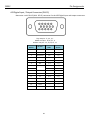
AES DIGITAL INPUT / OUTPUT CONNECTORS (DB-15) .................................................................................................................. 62
UPDATING FIRMWARE .............................................................................................................................................. 63
PRODUCT SUPPORT .................................................................................................................................................. 64
MAXX SPECIFICATIONS.............................................................................................................................................. 65
ZAXCOM WARRANTY POLICY AND LIMITATIONS........................................................................................................ 66
5
NOMAD LAYOUT
Front Panel
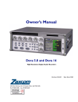
Know Your Maxx
Front Panel
1
2
3
4
5
6
7
8
9
10
11
12
13 14
15
16 17
18
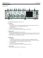
1. Wireless Camera Link Antenna - SMA connector
2. TC / REC Key
• In shifted mode
• A quick press opens the time code slate - additional presses will open the time code menus.
• Pressed and hold for one second, puts Maxx into record.
• In un-shifted mode
• A quick press will puts Maxx into record.
• When in setup menu press it to access the analog input 1 setup menu.
3. Red Record LED
When illuminated indicates Maxx is in Record mode.
In the Warning Setup Menu Maxx can be set up that if you are recording just to the primary folder
the LED will flash red, and when Maxx is mirroring the LED will go to solid red. This is to warn the
user that Maxx is not in Continuous Mirror Mode.
4. BUS /PLAY key
• In shifted mode
• A quick press access the bus menu – additional presses accesses additional bus menus.
• When in the ENG Home Page a single short press allows you to access the quick pan matrix.
• Pressed and held for one second, puts Maxx into playback mode.
• In un-shifted mode
• A quick press will put Maxx into playback.
• When in setup menu press it to access the analog input 2 setup menu.
5. Green Play LED
When illuminated indicates Maxx is in Playback mode.
6
NOMAD LAYOUT
Front Panel
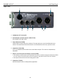
6. SETUP / STOP Key
• In shifted mode
• A quick press will open up the setup menu.
• Pressed and held for one second, will stop recording or stop playback.
• In un-shifted mode
• A quick press will stop recording or playback.
• A quick press with stop recording or stop playback.
7. Yellow Stop LED
When illuminated indicates Maxx is in Stop mode.
8. TONE Key
• Press to toggle Tone on and off.
• When in setup menu press it to access the analog input 4 setup menu.
9. Internal Slate Microphone
10. Color LCD Screen
Daylight-readable color LCD screen.
11. HEADPHONE Knob / BACK Knob
• Press knob to back out of a menu to the previous menu.
• Turn knob to adjust headphone volume.
• Press and hold will enter user inputted data.
12. Star key
• From the any home page, it advances to the next home page.
• In the bus routing matrix and Card Mix matrix if pressed it you will add phase reverse to your cross
point options.
• In the fader assign matrix if pressed it will add trim to your cross point options.
• If pressed and held while powering-up, Maxx will look for new software and start the update
process.
13. Fader 1 (4 total)
Each of four faders can be assigned to any channel or combination of channels, or act as a hardware
trim knob.
14. Auto-TrimTM LED (4 total)
Indicates which fader is active for AutoTrimTM.
15. Pre Fader Listen key (4 total)
• Press to listen to Pre Fader audio from the corresponding fader.
• When in setup mode press to access the AES input setup menu for the corresponding AES inputs.
• Pressing from the Meta Data menu or Track Naming menu will open the list of presets.
16. SLT key
• Press and hold key to activate the slate microphone.
7
NOMAD LAYOUT
Front Panel
17. Power Key
• A quick press will power up Maxx.
• Press and hold for 3 seconds to power down. Release the key when the countdown reaches 1.
• When Auto-Pan is ON the power key will change the panning for the active channel.
18. MENU knob / SHIFT key
• From the home page press it to access the Main Menu page.
NOTE: From the AES Virtual Fader meter screen or from the ENG meter screen, when you have
virtual faders engaged, you have to push and hold to access the Main Menu.
• Turn it to scroll through the items in a menu.
• Press to select a menu item.
SHORTCUT: While scrolling through a parameter with a long list, pressing the MENU knob while
turning it will speed up the scroll speed by 10 times.
8
NOMAD LAYOUT
Left Side Panel
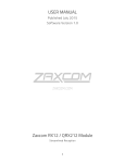
Left Side
1
5
2
3
4
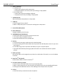
1. Battery Door
The Silver knob rotates clockwise to lock the battery compartment door. Inside, you will find space
for the battery carrier that holds six AA batteries.
NOTE: It is possible to insert the battery carrier incorrectly. Even if you insert with the contacts
reversed it will do NO harm to the unit because there is reversed current protection. It just won’t
turn on.
WARNING: Use ONLY NiMH rechargeable or Lithium batteries. If you use ANY other batteries, they
will EXPLODE and can SEVERLY damage or DESTROY the unit.
2. AES Input Output connector / GPI (DE-15F)
Maxx has AES 2 input pairs and 3 AES output pairs. The Input has a sample-rate conversion, allowing
each input to have a different sampling-rate. Maxx will accept any unlocked AES signal with a
sampling-rate of 44.1 to 96 kHz. The dynamic range of the sample-rate conversion is 124 dB, offering
completely transparent conversion of digital audio from one sample-rate to another.
3. Time code Input / Output connector (BNC) - the function of this connector is set in the time code
setup menu.
4. Compact Flash Card Mirror Media Slot
Compact Flash card is inserted with the top of the card (Label side) facing down.
WARNING: Take your time when inserting a card in Maxx. The card should slide in easily. If there is
any resistance required the card is not aligned correctly and can bend the pins.
9
NOMAD LAYOUT
Left Side Panel
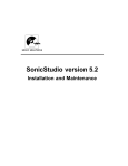
Right Side
1
2
3
4
5
6
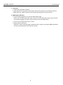
1. Headphone (1/4” stereo jack)
2. External Power connector (Hirose- HR10A-7P-4P)
10 to 18 VDC {1/2 A @ 12 VDC}
3. Tape / Mono Out (TA-5M)
Outputs both the tape and mono out busses. The tape and mono out are both balanced mono
sources. The audio that is fed to these busses are controlled from the mono / tape bus matrix.
4. Output Bus 1/2 (TA-5M)
This is an isolated feed of the audio sent to the XLR bus outputs. The Levels are independently
adjustable.
5. Return / Line Level Inputs for analog in 5 and 6 (TA-5M)
• This is where a camera returns are connected. The return is wired to accept two channels of audio
so it can receive one stereo return from one camera or two mono returns from two cameras.
• This input can be used as line level analog input 5 and 6.
6. Output Bus 1/2 (XLR)
Main XLR output. Levels are independently adjustable.
10
ZAX- MAXX LAYOUT
Rear
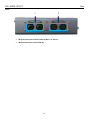
Rear
1
2
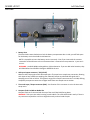
1. Mic/Line-level Inputs 3 and 4 (Combo XLR-3F 1/4" Stereo )
2. Mic/Line-level Inputs 1 and 2 (XLR-3F)
11
MAXX LAYOUT
Meter Screens
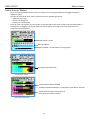
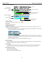
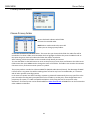
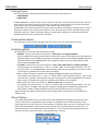
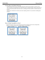
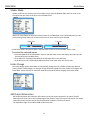
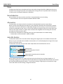
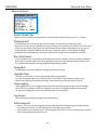
Home Screen / Meters
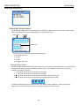
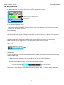
There are several selectable meter screens to choose from. Pressing the STAR key will toggle through the
different screens.
The color of the left half of the meter indicates the source type being metered:
• Light blue is an input
• Green is an output bus
• Purple is a recorded track
The track name, bus number or input number is indicated within each meter to aid in channel identification. If
a compressor is engaged, a white gain reduction line will appear at the right side of the meter when the
compression is being applied.
Output busses 1 and 2
Quick Pan Matrix
AutoTrim Meter / Virtual Faders for mixing Inputs
ENG Home Screen
Input signal from XLR Inputs
4 Input Home Screen
Yellow ISO Attenuation Enabled
Red Record Enabled Indicators - shows which tracks will be recorded
Yellow Strike Through – Represents that
these tracks will not be recorded
Card Track Home Screen
12
MAXX LAYOUT
Meter Screens
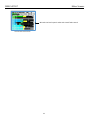
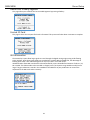
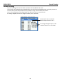
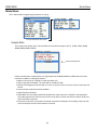
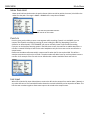
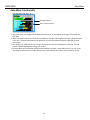
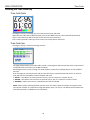
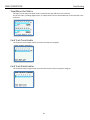
AES and Line level inputs 5 and 6 with virtual fader control
Virtual Fader Home Screen
13
MAXX LAYOUT
Meter Screen Explained
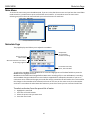
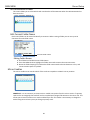
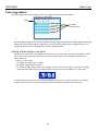
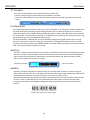
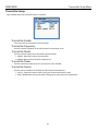
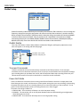
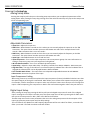
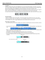
Home Screen Explained
Time code
Transport Status
Headphone Selection
Battery
Indicator
Card information field
Limiter reduction indicators
Peak Hold Indicator
ENG Panning shortcut
Matrix
Input/Virtual Fader
Meter
Trim Level Indicator
Save Indicator
Transport Status
Shows the mode of recorder RECORD, PLAY or STOP.
Time Code
Shows the current time code.
Headphone Selection
Displays which headphone matrix is being monitored. You can custom name your headphone set up - see
headphone naming in the ENG menu.
• If the PFL key is pressed, the name in the Headphone Monitor field is replaced with “PFL” alternating
with the selected channel number(s) as follows:
Shows what is
being listened to
in PFL mode
• Press the PFL key corresponding to input to select a channel to PFL. If you want to listen to multiple
channels at the same time, just press and hold an additional PFL key for approximately 1 second to add
that channel to the PFL circuit.
• Press the headphone knob to restore normal headphone monitoring.
Battery Indicator
Displays the power source (I - Internal / E - External), a numeric display of the current voltage. Maxx will
always automatically switch to the higher voltage source first.
Save Indicator
A moving pixel on bottom of screen moving right to left indicates that the Maxx is saving a parameter
setting to its memory. If you power down while the pixel is moving the settings will not be saved.
Card Information Field
Top Line - Mirror Free Space
Second Line - Mirror File Progress
Third Line -Time left on the Primary Folder
14
MAIN MENU
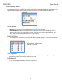
Metadata Page
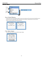
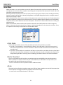
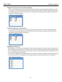
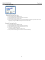
Main Menu
To access the main menu press the MENU Knob. If you are in the ENG home screen and you have the virtual fader
mode turned on, you will have to press and hold the menu knob for 1.5 seconds to enter the main menu.
Selecting any item in the main menu will take you to the sub menus for each item.
Scroll for additional menu items
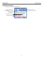
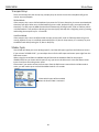
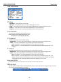
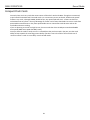
Metadata Page
This page displays and allows you to adjust the metadata.
Sample Rate
TC Frame Rate
Pre-Record setting
Primary Card Info
Mirror Status
Alternates between record time
& mirroring segment
Current Record Folder,
Scene, Take and Notes
To adjust the metadata use the MENU Knob to select and highlight one of the data fields then press the
MENU Knob to highlight the field.
Metadata can be edited and changed before Maxx starts recording a file or even while Maxx is recording.
And metadata changes made before a record take is stopped will be reflected in that take. If you are in
continuous mirror mode and changes are made after stop is pressed the file will need to be re-mirrored for
the changes in the metadata to be reflected in the mirror file. You can the scene name, the take number
and enter a note about the take. Maxx also features a preset list of notes you can create and recall from.
To select and enter from the preset list of notes
1.
2.
3.
4.
Highlight the note field
Press one of the PFL buttons
Select the preset note you want enter
Press the menu knob
15
MAIN MENU
Playback Page
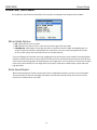
Playback Control Page
This page controls playback of recorded files.
Segment Time code
Segment Currently Playing
Playback Shuttle Control
Turn the MENU knob to adjust
Press and turn for
10X adjustment
Playing Segment Meta
Folder playing back
16
MAIN MENU
Record Setup
Record Card / Mirror Menu
The card/mirror menu sets the parameters of the primary recording and mirroring functions of Maxx.
Mirror Mode Options
• OFF - Maxx will not mirror any files.
• ON - Maxx will only start to mirror a file once the unit has gone into stop mode.
• CONTINUOUS - When Maxx is recording, the audio is copied to the mirror folder immediately after it is
written to the primary folder. Depending on the track count, the mirror card may lag behind a bit. Not
to worry, after you go into stop mode, the mirror card will catch up.
If you are finding that continuous mirroring is lagging you may be using too much of Maxx’s processing power
elsewhere. Many times there are items that are on that are on are not needed. These items can often be shut
off to conserve processing power and speed up the mirroring process. You can check to see that some of these
items are not unnecessarily on: bus assignments cross points, compressor enables (input, output and card),
high pass filters.
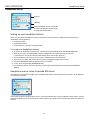
Write Sound Report
When selected, Maxx will create a sound report of the recorded files and write it on the mirror CF partition.
The sound report contains the metadata information for what was entered. Please note to write a sound
report mirror mode must be set to OFF.
17
MAIN MENU
Record Setup
Primary Record Menu
Choose Primary Folder
Green checkmark indicates which folder
receives the recorded audio.
NOTE: Mirror mode needs to be set to OFF
before you can change primary folders.
All files are recorded into individual folders. This menu lets you choose which folder the audio files will be
recorded to. To select a folder scroll the MENU knob to highlight the folder then press the MENU knob. At
that point the green check will indicate the folder that will be recorded to.
After selecting a folder that folder can be renamed to help identify its contents.
To name the folder hit the back button to return to the primary CF menu then scroll down to the Edit Current
Folder Name then press MENU Knob to change the name of the folder. The folder name needs to be nineteen
characters or less, and cannot contain spaces or symbols.
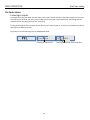
The primary audio is recorded as a Zaxcom MARF file (Mobile Audio Record Format). The advantage of MARF
is that if there is any power loss while recording there will not be any loss of recorded audio, as is common
with all other portable recording systems.
In the event of a power loss while recording: at power-up, Maxx will automatically close any open files to the
point the audio recording was interrupted with no loss of audio up to that point. Even though Maxx uses a
proprietary file system, it is 100% compatible with Mac or PC by using the free file conversion utility
ZaxConvert. The latest version can be downloaded from www.zaxcom.com. All MARF files can be converted to
either a BWAV or MP3 files.
18
MAIN MENU
Record Setup
Delete Last Primary Segment
This page allows you to delete the last recorded segment by pressing STAR key
Format CF Card
This page is where the compact flash card is formatted. This process will take about 4 minutes to complete.
ISO Attenuation
The NeverClip™ inputs allow large signals to travel through the digital mixing engine using 32 bit floating
point numbers. Once these large signals are recorded into a 24-bit WAV (or MARF) file, the advantage of
floating point math is lost and these signals can clip if you don’t use a card limiter.
ISO Attenuation allows ISO record tracks to be attenuated by a user selectable fixed amount of either 6, 12,
18 or 24 dB. This allows audio to be recorded un clipped, even if its dynamic range would normally be too
large. This gain reduction is stored in the metadata of the WAV file so post production can restore the
amplitude of the ISO tracks when necessary.
19
MAIN MENU
Record Setup
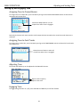
ISO Attenuation Enable
This matrix allows you to select which card record tracks will be attenuate when the ISO attenuation has
been turned on.
Edit Current Folder Name
Each record folder can be named to identify its contents. When naming a folder you can use up to 19
characters for each folder name.
Current folder name
Editing Folder Names
1. Scroll down to the Edit Current Folder Name.
2. Press the MENU knob to highlight the folder name and to access the enter text menu.
3. Name the folder keeping in mind that the folder name needs to be 19 characters or less, and
cannot contain spaces or symbols.
Mirror Enables
The mirror enable menu controls which of the tracks are copied on to Maxx’s mirror partition.
SHORTCUT: It is not necessary to remove mirror enable cross points from this mirror matrix If a primary
card track is not assigned, that track will not be recorded and noting will be written to the mirror file. This
allows you to leave all of the mirror tracks enabled if you like. This makes it unnecessary to change the
tracks being mirrored every time you change a primary track.
20
MAIN MENU
Record Setup
Mirror Settings Menu
The mirror menu controls the copying of the audio files from primary partition on the compact flash card to the
mirror partition. The mirror partition is formatted as FAT32, is fully compatible with all Mac & PC platforms and
is generally used as a deliverable format to post since the mirrored files will be recorded as BWAV files.
Mirror Mode
• OFF: Maxx will not mirror any files.
• ON: Maxx will only start to mirror a file once the unit has gone into stop mode.
• CONTINUOUS: When Maxx is recording, the audio is copied to the mirror card immediately after it is
written to the primary card. Depending on the track count, the mirror card may lag behind a bit. Not to
worry, after you go into stop mode, the mirror card will catch up.
Folder to Mirror
This menu specifies which folder the primary audio will be mirrored (copied) to. If you want to continuous
mirror, this folder needs to match the primary folder.
Green checkmark indicates which
folder will be mirrored.
Start Segment
This will set the first segment that Maxx will mirror or re-mirror. As you are recording the start segment will
automatically increment with each file on the primary card.
End Segment
This sets the last segment that Maxx will mirror or re-mirror.
21
MAIN MENU
Record Setup
File Type Select
File select sets the file format type Maxx will mirror the audio as the choices are:
• BWAV MONO
• BWAV POLY
A BWAV MONO file is 1 file per track. So if you record 1 track only, 1 file will represent that "take" from the
time you press record to the time you press stop. If you were to record 2 tracks for that same take, Maxx
will produce 2 files, one representing track 1 and the other representing track 2.
A BWAV POLY file creates one file for that take; even if the take was recorded has multiple tracks. So with a
POLY file if a take is only 1 track the file would be 1 track. If the take was 2 tracks, it would still be one file
with both tracks. This is often referred to as being "2 tracks wide". Similarly, if 6 tracks were recorded it
would still be only one file, but will be 6 tracks wide.
File Resolution Select
File resolution sets the bit depth that Maxx will mirror files at. You can choose 16 bit or 24 bit.
File Naming Style
File naming sets the way your individual files are named.
• Z001001 - Creates a file name in the format of - Folder Name and Segment Number.
This is the default file naming protocol where the file name consists of the Folder Name followed by the
Segment Number. So for example file number 45 in folder 1 the file name would be Z001045.WAV that
would be followed by file Z001046.WAV. If you change the folder name (for example Maxx) the file
name would be Maxx045.WAV
• 1 T2 Z001 - Creates a file name in the format of - Scene, Take, Folder Name and Segment Number.
So for example if you record scene “1”, Take “2” in folder “Z001” and the segment number is “45”, the
file name will be “1_T2_Z001045.WAV”. Warning when using this naming option do not create a scene
or take with any characters other than letters or numbers.
• 1 T2 - Creates a file name in the format of – Scene and Take separated by and underscore.
For example if you record scene “1”, Take “2” in folder “Z001” and the segment number is “45”, the file
name will be “1_T2.WAV”. Warning when using this naming option avoid creating duplicate file names
within a folder, if duplicate file names are created the files will not mirror properly.
• 1T2- Creates a file name in the format of - Scene and Take with no separation.
For example if you record Scene is “1”, Take “2” in folder “Z001” and the segment number is “45”, the
file name will be “1T2.WAV”. Warning when using this naming option avoid creating duplicate file
names within a folder, if duplicate file names are created the files will not mirror properly.
Please note that all segment numbers will be a three digit number. And the first file in all folders will
always be 001.
Mirror Options
This setting allows Maxx to stay in the last mirror mode setting before being been powered off. If this
option is set to OFF, any time Maxx is powered down it changes the mirror mode to OFF then when
powering back up you will need to turn mirroring back on regardless what your mirror setting was set to.
Please note even if Maxx is setup to allow mirroring mode to be remembered after a power cycle - if a
compact flash card is not installed after the unit boots-up - mirror mode will be turned off and must be
manually turned on by the user when a compact flash card is inserted.
22
MAIN MENU
Record Routing
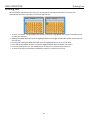
Record Routing
The record routing menu controls what is routed to and recorded to each track
In the record routing page by using the MENU knob you will select and highlight which card track you want to
record to then you can choose what source you what to assign and record on that channel.
You can choose between all 6 analog inputs, the 4 AES inputs or the 2 output busses.
All analog or digital inputs can be assigned as either pre or post fade.
Shows Card Tracks 1 and 2 will
Record Output Busses 1 and 2
All Analog and Digital inputs can be
routed as either Pre or Post Fader
23
MAIN MENU
Fader Assign
Fader Assign Matrix
The fader assign matrix controls which inputs are assigned to the four hardware faders.
Input
Hardware
Fader Number
Because Maxx is a digital mixer, no actual audio is going through the fader control which allows for complete
flexibility for the hardware faders assignments. So any one of the analog inputs 1-6, digital inputs 1-4, or
analog trim controls can be assigned to any of the 4 hardware faders.
Setting a fader assign cross point
Rotate the menu knob to scroll through the matrix. Stop at the intersection of the input and fader number
where you want to send that specific input. Press the menu knob to cycle through the available cross
points, which are:
• Blank - no connection.
• A - Assign an analog input to a fader.
• D - Assign a digital input to a fader.
• T - Assign the fader knob to work as a hardware trim knob. Please note that to access the trim assign
option you will need to press the STAR key when in this matrix. That will add the “T” to the cycle.
It is important to note that if you are using a multiple-element mic (i.e., stereo, surround, etc.) and you
assign all of the channels to one master fader you need to disable auto trim in the mode menu.
24
MAIN MENU
Memory Menu
Memory Menu
Memory
Store
Positions
Memory
Recall
Positions
Scroll for additional menu items
Store / Recall Memory
From the store and recall positions, Maxx can save and recall three full recorder setups for different work
scenarios. All user set parameters are saved and can be recalled as needed. Note if you do a factory
restore, all of the saved memories will be erased.
Clear Fader Assigns
This menu clears all of the current fader assign settings.
25
MAIN MENU
Memory Menu
Factory Reset to Default Settings
From this page is where you can resets all the parameters back to factory default. If a factory reset is
done, all of your user setting will be lost and will have to be re-inputted. Though a factory restore will not
erase note and track presets. To do a full restore - including note and track names - hold the stop key on
boot up.
Please note it is advised to do a factory reset when updating software or if your Maxx is exhibiting odd
behavior.
Store / Recall using Mirror Card
Maxx has the option to save its user settings to (and restore settings from) the mirror compact flash
partition. This allows settings to be exchanged between multiple Maxx’s.
26
MAIN MENU
About Maxx Page
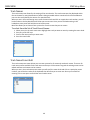
About Maxx Page
This page gives you information about your Maxx
27
MAIN MENU
Mode Menu
Mode Menu
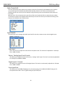
This is where Maxx’s engineering parameters are set up.
Scroll for additional menu items
Sample Rate
This is where the sample rate is selected. Maxx can record with sample-rates of: 44100, 47952, 48000,
48048, 88200, 96000, 192000
Selected Sample Rate
Please note that when recording files at a high sample rate of 88200, 96000 or 192000 there are some
limitations to Maxx’s recording parameters.
• Maxx will record up to 4 analog iso inputs pre-fader only.
• Fader assign will be disabled – all inputs will be routed pre-fader
• Record track assignments will be Input 1 to track 1, input 2 to track 2, input 3 to track 3 and input 4 to
track 4.
• Input and card compressors will be disabled.
• NeverClip will be disabled.
• While Maxx will record time coded files the BNC time code connector is disabled - meaning Maxx’s
time code generator will function but you will not be able to receive external time code or send time
code via the BNC connector.
• Prerecord is limited to 2 seconds for all sample rates with the exception of recording more than two
tracks at 192K pre-record will be limited to 1 second.
28
MAIN MENU
Mode Menu
TC Transport
Time code transport adjusts the way Maxx will go into record mode.
• Normal - Maxx will go into record when the record button is pushed.
• Auto-Load - Maxx will go into to record with it senses record run time code coming from an external
source.
Pre-Record Set
Pre-record allows Maxx to buffer the audio into a pre-record buffer. From the point the Maxx is powered up,
any audio coming from the input is always being processed. You can choose to buffer up to 5 seconds of
audio. When pre-record is enabled, the processed audio signal d is held in the buffer until you press the REC
key. At that time, all stored audio in the buffer is included the current take with the correct time code. Using
prerecord does not use up any additional battery power.
The prerecord buffer is dumped after any of the following settings are changed: sample-rate, time code,
user-bits, frame-rate or track count. After these parameters are changed the buffer will start to re-build.
Prerecord is limited on sample rates of 88200, 96000 to 2 seconds. When recording more than two tracks at
192K - then prerecord will be limited to 1 second.
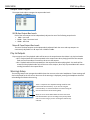
AutoTrim
AutoTrim is a feature that makes the menu knob act an individual trim knob for all you analog inputs. When
AutoTrim is turned on and you adjust a fader the blue LED next to that fader will illuminate indicating the
input routed to that fader will be trimmed when you rotate the menu knob. When you adjust another
fader, the trim function will move to that input.
Input being controlled
Trim Level Indicator
AutoPan
AutoPan is a feature that causes the Power key act as a pan knob. When AutoPan is turned on and you
adjust a fader the blue LED next to that fader will illuminate indicating the input routed to that fader will be
panned when the Power key is pressed. AutoPan is active from any meter screen.
When pressing the Power key the panning for the illuminated channel will cycle from left to center to right
to blank - unless “Prevent Empty Pan” is turned ON then the blank option will not be cycled through.
As you pan with AutoPan the headphone display will temporally show which input is panned to which
position.
Analog input 1 panned Left, Center, Right
29
MAIN MENU
Mode Menu
Transport Keys
There are two ways that the record, stop, and play keys can be set to control the way Maxx will go into
record, stop and playback.
Shifted Mode
If the transport key is set to shifted mode and you press the TC, Bus or Setup key, the menu associated with
those keys will open. When set to shifted mode to go into record, playback or stop, you would need shift
those keys. To shift press the MENU knob while simultaneously pressing the REC, PLAY or STOP key. While
in shifted mode it is still possible to directly go into record, play and stop with a single key press by pressing
and holding the transport key for 1.5 seconds.
Unshifted Mode
If the transport key is set to unshifted mode and you press the REC, PLAY or STOP keys Maxx will go into
record, playback or stop. In unshifted mode to display the TC, Bus or Setup menus, it is necessary to press
the MENU knob while pressing the TC, Bus or Setup key.
VFader Cycle
Virtual fader will allow you to mix Analog inputs 5, 6 and the AES inputs right from the ENG Home screen.
If you activate “VFADER CYCLE”, you can adjust the mix for the AES inputs and return inputs right from the
ENG Home screen.
When using the virtual faders the MENU knob will become the hardware fader for those inputs.
VFADER CYCLE lets you choose which inputs (if any) you want to be able to mix in the ENG Home screen:
Inputs 5 and 6 are the analog return inputs.
Please note if you need to access the main menu from the ENG meter screen while the VFader mode is
active, you will need to press and hold the MENU knob for 1.5 seconds
Shows which inputs will be available
when the Virtual Fader is activated
30
MAIN MENU
Mode Menu
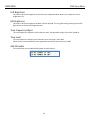
VFader Mode
VFader mode lets you choose to control the fader only or alternate between fader and trim controls for
the inputs that you chose to be active in the VFADER CYCLE.
When the virtual faders are active the bottom meter on the ENG Meter Screen will display what you will
be controlling. Either fader only or fader and trim for an input channel can be selected.
Fader Icon
Trim Icon
Virtual fader mode is only active while in the ENG meter screen or the virtual fader .meter screen
To control the selected inputs:
• Press the MENU knob and the bottom meter on the ENG meter screen will display what input you will
be controlling with the MENU knob.
• If the fader icon is displayed the MENU knob will adjust the mix for that input.
• If the blue trim icon is displayed the MENU knob will control the input trim of that input.
Folder Change
The folder change option allows Maxx to automatically change the mirror folder to follow the selected
primary folder. If AutoChange is on and you change the primary folder the mirror folder will change to the
same folder. Please note mirror mode still needs to be turned off before changing the primary folder.
AES Output Attenuation
AES output attenuate will reduce the AES output level by the amount selected in the menu. The AES
attenuation will allow you to take full advantage of the dynamic range of the Never Clip inputs. The output
attenuation works the same way as the ISO attenuation on Maxx’s record tracks works.
The adjustable range is from 1dB to 20dB in 1dB increments.
31
MAIN MENU
Mode Menu
Meter Peak Hold
Meter peak hold sets the duration the peak indicator (white vertical bar within the meter) is held after the
audio hits that peak. The range is 400MS – 8000MS with a step value of 200MS.
Time that the peak hold indicator
will remain on the meter.
Punch-In
Punch in gives you the ability to start a new segment while recording. If punch-in is ALLOWED, you can
create a new file while recording by pressing (or press holding) the REC key (depending if you are in
shifted or un-shifted mode). If it is DISABLED, you cannot manually create a new file while recording.
If you turn on the Rec/Stop warning option in the ENG Home screen, there will be an audible beep when a
new file is created. The beep is heard in the main headphones only and is not sent to the record tracks or
output busses.
Please note that Maxx will automatically create a new file when the file size reaches 2GB. This will be a
seamless transmission with no loss of audio. The take number will add a letter for each time Maxx creates a
new file. So for example if the first take is over 2GB the take numbers would be Take1 and Take 1a.
Link Input
When set to ON the link input allows Maxx to receive the AES mix bus output from another Maxx / Nomad, or
any other AES source. The received AES audio channels are mixed individually to the output bus of Maxx. This
links the two recorders together allows more inputs to be mixed to the output busses.
32
MAIN MENU
Transmitter Setup Menu
Transmitter Setup
Only available when the transmitter option is installed
Transmitter Enable
Turns ON / OFF the UHF camera link transmitter.
Transmitter Frequency
Sets the transmit frequency of the UHF camera link transmitter is set.
Transmitter Mode
Sets the transmit mode of the UHF camera link transmitter.
• MONO - Maxx will transmit one output bus.
• STEREO -Maxx will transmit both output busses.
Transmitter Power
Sets the transmitter power level. You can select 25, 50 or 100mW
Transmitter Source
Sets the source of audio that will feed the UHF camera link transmitter.
• OUT 12 - Maxx will transmit what is being sent to the output buses 1 and 2.
• TAPE / MONO-Maxx will transmit what is being sent to tape and mono output buses.
33
MAIN MENU
Auto Mixer
Auto-Mixer
When Auto-Mixer is on, and a speaker starts to talk, Maxx will automatically open that microphone and add that
microphone to the mix. Then when a speaker stops talking that microphone will be attenuated “closed” and it will
essentially be removed from the mix.
Removing unused microphones will result in a lower noise floor giving you a cleaner, better sounding mix without
having to manually ride the faders. Manually riding faders in unscripted dialog often results in missing the start of
when a person begins to speak.
Maxx’s Auto-Mixer has no limit on the number of microphones that can be active at one time. The Auto-Mixer also
has a last microphone on feature; this means that even if no one is speaking there will always be one microphone
included in the mix, which will be the last active microphone. The last mic on feature allows the mix to never go to
absolute silence.
Please note Auto-Mix will be routed to the output bus selected in the A-Mix Enables menu. When using AutoMixer it is important that you remove all cross points in the Bus Assign Matrix for the chosen bus or busses. If any
cross points are active they will be mixed into the Auto-Mixer audio.
A-Mix Mode
Enables Maxx Auto-Mixer and sets if the Auto-Mixer will work either pre-fade or post-fade.
• Pre-Fade - The Auto-Mixer is inserted before the faders in the audio chain so only the trim control will
affect the microphone levels. Since the Auto-Mixer is before the faders the faders have no effect on the
Auto-Mix levels.
• Post-Fade - The Auto-Mixer is inserted after the faders in the audio chain and both the trim and the faders
will control the levels of the microphones. In post-fade mode you can pull a microphone out of the mix by
simply lowering the fader. This way if you are recording a pre-fade iso tracks it will remain un-affected.
Mic On Threshold
The mic on threshold sets the level that a microphone needs to reached before that microphone opens.
When a speaker’s microphone reaches the mic on threshold level, as indicated on the input meter, that
microphone will open and become part of the mix.
• Mic On Threshold can be set anywhere between -60dB and -10dB
Attack
The attack sets how fast the microphone ramps up to full level when a speaker starts to talk. Please note that
the microphone will engage immediately regardless of the attack setting.
• Attack can be set anywhere between 1 and 150ms
34
MAIN MENU
Auto Mixer
Decay
The decay sets how long a microphone will stay active after the signal has fallen 10dB below the mic on
threshold. This setting is to prevent a microphone from closing too soon if a speaker takes a brief pause.
• Decay can be set anywhere between 1 and 150ms
Noise Reduction
Noise reduction sets how much the noise floor is attenuated when no one is talking.
• Noise Reduction can be set anywhere between 0dB and -10dB
Attenuation
The attenuation sets how much each microphone is attenuated when a person stops talking.
When a person stops talking that microphone is not completely closed but that microphone is actually
attenuated. That level of attenuation is adjustable through this menu setting. In some environments it
may be more palatable to hear some or most of the ambient microphone noise all the time rather than
hear the noise mute and then re-appear when someone talks. Regardless of this setting the last active
microphone will always remain open.
If you want the microphone to completely close you can the attenuation at its lowest setting.
• Attenuation can be set between -10dB and -80dB
Auto-Mix Enables
The Auto-Mix enable matrix sets which of the analog and or digital inputs are included in the Auto-Mix.
When an input is selected to be included in the Auto-Mix an “A” will be displayed to the right of the input
meter on the meter screen.
The Auto-Mix matrix also lets you select which output buses the Auto-Mix will be sent to.
Analog Inputs
Returns (analog input 5 and 6)
Digital Inputs
Selects which output busses the Auto-Mix
will be routed to
When assigning Auto-Mix to an output mix bus that bus should not have any thing assigned to it. If
something is assigned to an output bus with the Auto-Mixer the assigned audio will be mixed into the AutoMix essentially defeating the Auto-Mixer. To verify that nothing is assigned go to the output bus assign
matrix and make sure that nothing is assigned to that bus.
35
MAIN MENU
Auto Mixer
Auto-Mixer Functionality
Auto-Mix indicator
Active channel indicator
• After your inputs are assigned to the Auto-Mixer the letter “A” will appear to the right of the meter for
that input.
• When that input is active the “A” will be replaced by a blue dot indicating that the input is being included
in the mix. If multiple microphones are opened at the same time Maxx will display a blue dot for each
active input.
• You will want to make sure all bus routing is cleared for bus that the Auto-Mixer is routed to. This will
prevent unwanted audio from mixing into the bus.
• The Auto Mixer will not be able to differentiate between a speaker’s voice and noise such as a hit to the
microphone. So if the noise is louder than the mic on threshold that will open the microphone as well.
36
MAIN MENU
ZaxNet Menu
ZaxNet Setup
ZaxNet functionally in Maxx will allow you to remotely control Zaxcom TRX transmitters. You can change the
frequency, change the input gain, apply power roll and start and stop the transmitter’s recorder remotely.
When you adjust the transmitters’ parameters with-in Maxx the change commands will then be embedded
in the time code stream out of Maxx. Then all you have to do is input Maxx’s time code into a ZaxNet
transmitting device such as the IFB100, IFB200, TRX900 Camera Link transmitter, QRX100 (with QIFB), or
QRX235 (with QIFB). Then those devices will send the commands to the transmitters.
ZaxNet Enable
Turns ON / OFF ZaxNet in Maxx. When ZaxNet is enabled the TRX gain and frequency adjustment menu
items will appear in the analog and AES setup pages.
Transmitter trim control
Transmitter frequency set
Transport Commands
Transport commands will send record and stop commands to the TRX transmitters. If the transport
commands are set to slaved the transmitters, that are set up to receive ZaxNet record commands will begin
start recording when you put Maxx into record, and will stop when Maxx stops recording. Please see your
TRX transmitter manual to set up the transmitters to receive the record commands.
Power-Roll Mode
Power roll allows the transmitters that are being controlled via ZaxNet to increase its output power level
when Maxx goes into record, and decrease to a lower power setting when you stop recording. By decreasing
the power level when you are not recording allows you to conserve the battery on the transmitter. To use
power-roll the TRX transmitters power-roll setting must be set to “Deva Trigger”
The power-roll settings in Maxx are:
• ALWAYS LOW - The transmitter will always run at the low power setting.
• DYNAMIC - The transmitter will run at low power between takes and automatically go into high power
when Maxx goes into record.
• ALWAYS HIGH - The transmitter will always be run at the high power setting.
37
MAIN MENU
ENG Setup Menu
ENG Setup
Scroll for additional menu items
Scroll for additional menu items
Compressor Enable
The compressor matrix sets which card tracks, output busses, and if the tape out or mono out will have a
compressor (limiter) enabled. Placing an X in the matrix will enable the compressor to that card track, output
bus and or tape and mono out.
Assigns which card tracks will
have a limited applied to it.
Assigns compressor to the output buses,
tape output (T), and mono output (M)
Input Compressor Parameter Adjust
This menu sets the parameters for the input compressor. The Input Compressor settings are global, meaning
that the settings adjusted here will be the same for all input Channels.
38
MAIN MENU
ENG Setup Menu
Output Compressor Parameter Adjust
This menu sets the parameters for the output compressor settings. These settings will be applied to the two
output busses as well as the tae and mono output. The output compressor settings are global, meaning that
the settings adjusted here will be the same for all output busses. The parameter for the output compressors
allows you to add makeup gain.
Card Compressor Parameters
This menu sets the parameters for the card compressor settings. The card compressor settings are global,
meaning that the settings adjusted here will be the same for all card tracks. The parameter for the output
compressors allows you to add makeup gain.
Headphone Names
Maxx allows you to customize the headphone monitor names that appear in the home screens. When you are
in the headphone set up menu once scroll the menu knob and click on a particular HP number, you will be then
taken to the keyboard that will allow you to enter text. Once you are finished entering in the headphone name
press and hold the menu knob to enter.
If you create a headphone name labeled “PLAY” when you go into playback mode Maxx will automatically jump
to this preset, when hit press stop Maxx will automatically return to the last preset you were listening to.
39
MAIN MENU
ENG Setup Menu
Track Names
The track name menu allows for the naming of the record tracks. The track names are then displayed within
the card meters for easy identification of what is being recorded and are contained in the files metadata so
post can also easily identify the source of a recorded track.
When you are in the track naming menu scroll the menu knob and click on a particular track number, you will
be then taken to the keyboard that will allow you to enter text. Once you are finished entering in the
headphone name press and hold the menu knob to enter.
Maxx also allows you to choose from a preset list of track names that you can create
To select from the list of Track Preset Names:
1.
2.
3.
4.
When you are in the track name menu highlight the track you want to name by rotating the menu knob.
Press any of the PFL keys.
Scroll to the name preset you want enter.
Press the menu knob.
Track Name Preset Edit
The track name preset menu allows you to create a preset list of commonly used track names. There are 20
track name presets available. Each track name can be up to 22 characters long and the existing names can be
edited and new track names can be created.
When you are in the track name preset menu you will scroll the menu knob and click on a particular preset
number, you will be then taken to the keyboard that will allow you to enter text. Once you are finished
entering in the name press and hold the menu knob to enter.
40
MAIN MENU
ENG Setup Menu
Note Preset Edit
The note name preset menu allows you to create a preset list of commonly used metadata notes. So when
you are entering in the metadata you will be able to quickly choose a note. There are 20 note presets
available and ach note can be up to 25 characters long. All existing notes can be edited and new names can
be created.
When you are in the note preset menu you will scroll the menu knob and click on a particular note number,
you will be then taken to the keyboard that will allow you to enter text. Once you are finished entering in the
note press and hold the menu knob to enter.
Input Levels
The input levels menu manages the audio input levels for the slate, camera returns and the digital inputs.
Slate Level
Here is where you can adjust the internal slate microphone level. The slate level is adjustable in 1 dB steps
from -12dBu to 21dBu.
Return / Analog Input 5 and 6 Levels
This allows you to adjust the levels of the return / analog 5 and 6 inputs. The level is continuously adjustable
in 1 dB steps from-20dBu to 30dBu.
Digital Inputs 1-4 Levels
This allows you to adjust the levels of the digital inputs. The levels are continuously adjustable in 1 dB steps
from -20dBu to 30dBu.
Extra Input Gain
This allows you to add 10dB of digital gain to your inputs giving you an additional 10dB of input gain for
microphones that need it. This is a global setting for your XLR inputs.
41
MAIN MENU
ENG Setup Menu
Output Levels Adjust
The output levels adjust manages the output audio levels.
XLR & Aux Output Bus Levels
Each of the main output can be independently adjusted to one of the following output levels.
• 0dBu - Line Level
• -10dBu - Tape / Consumer Level
• -35dBu - Mic Level
Mono & Tape Output Bus Levels
The mono and tape outputs can be independently adjusted. Both the mono and tape outputs are
continuously adjustable in 1 dB steps from -12dBu to 21dBu.
Play to Outputs
Play to outputs sets if the playback audio will be sent to the output busses when Maxx is in play back mode.
• OFF - Playback audio will not be outputted to the output buses when playing back from the compact
flash card and live audio will continue to be sent to the outputs.
• ON - Playback audio will be outputted from the output busses when playing back. Live audio will be
muted and the playback audio only will be sent to the outputs, when stop is pressed Maxx will resume
sending live audio to the output busses.
Warnings Setup
The warning setup menu manages the audible alerts that are sent to the main headphones. These warnings will
also be displayed on the LCD screen. Once one of the warnings is displayed, pressing the headphone knob will
acknowledge and dismiss the warning.
There is a separate user adjustable voltage cutoff for both
internal and external battery - if you are not using the
internal battery it is recommended to turn that warning off.
Sets the volume level of the warning beep.
When set to on the No-Mirror Blink sets if the red record
LED will blink when you are recording to the primary folder
and are not mirroring. If you are mirroring the LED will stay
solid red.
42
MAIN MENU
ENG Setup Menu
LCD Brightness
This menu is where the brightness of the LCD screen is adjusted. Maxx allows you to adjust the screen
brightness to 11.
LED Brightness
This menu is where the brightness of Maxx’s LEDs is adjusted. This is a global setting meaning that all LED
lights will be set to the same brightness level.
Tone Frequency Adjust
This menu adjusts the frequency of the reference tone. The adjustable range is from 20 to 20,000 Hz.
Tone Level
This menu adjusts the output level of reference tone. The range is -90 to 0dB.
Please note it is recommended for most applications to keep the tone level set at -20dB
AES 42 Enable
This menu allows you to Enable AES-42 power for each AES pair.
43
MAIN MENU
Advanced Setup Menu
Advanced Setup
Prevent Empty Pan
When set to on, the blank (no assign) option is removed from AutoPan leaving only the L, C, R option.
Display Speed
The display speed sets the refresh rate of the LCD display. This should normally be set to FAST.
When set to fast the display is updated every frame. Though if you are using a lot of effects and cross points
and/or are recording at a high sample rate and find that the user interface is getting hard to use, you can
change the display speed to SLOW to slow down the refresh rate. Please note the display speed will
automatically go into SLOW when mirroring or when the unit needs more horsepower for recording.
Burn Boot loader
The boot loader is part of the software that helps boot up Maxx. Generally, you will not need to update the
boot loader. If the boot loader needs to be updated there will be a note released with the software to do
so. The boot loader software is already contained within Maxx’s software.
Debug Bits
The debug bits are a factory diagnostic setting and should stay set to 0.
Upgrade Code
This page is used to enter in a factory generated code to upgrade Maxx.
To enter the upgrade code you must directly enter in the code by using the alpha / numeric multifunction keys. Warning by randomly entering in code numbers can cause your Maxx to lock up.
Allow Logging
Allow logging will turn on the logging feature which will allow Maxx to log warning and error messages
which then can be used by the factory to diagnose your Maxx. The logged messages are displayed on
the log screen. If logging is not turned on then Maxx will not log the errors.
Log Screen
This is where Maxx displays the logged errors and warnings.
Slate Always On
Normal - This is the typical setting that would be used. With this setting pressing and holding the slate
key will activate the slate mic and releasing the key will deactivate the slate.
• Forced - When you activate the slate mic this setting locks the slate mic in the on position. Note a power
cycle will be needed to deactivate the mic.
•
44
MAXX OPERATIONS
Time Code
Pressing the Time Code Key
Time Code Slate
Pressing the TC Key once brings you to an inverted visual time code slate.
When the time code slated is displayed and you press the MENU knob, the time code will briefly freeze
and a 1-frame slate tone will be sent to any bus that has tone routed to it.
This is used to provide a visual sync for the camera to match picture and sound.
Time Code Jam
Pressing the TC Key a second time brings you here.
This page displays Maxx’s time code reader, which is receiving time code and user-bits from a source that is
connected to the time code in on the BNC connector.
Also displayed is the current running time code of Maxx’s internal time code generator, as well as Maxx’s
user-bits.
From this page you can jam the time code and user-bits from a connected time code source or jam time
code and user-bits from Maxx’s internal calendar and clock.
• JAM TC – Jams Maxx’s TC from an external source, such as a camera or a master TC unit.
• JAM UB – Jams Maxx’s user-bits from an external source, such as a camera or a master TC unit.
• JAM DATE – Maxx’s user-bits are created from the internal calendar.
NOTE: Maxx contains a battery backed real-time clock. This clock is used to maintain running time code
and internal calendar. It is advised to change the battery every 2 to 3 years. The battery that maintains the
time code and clock is a CR2320 3V coin cell battery.
45
MAXX OPERATIONS
Time Code
Enter Time Code
Manually Entering Time Code
1.
2.
3.
4.
Press the MENU knob to highlight the TC.
Rotate the MENU knob to select the desired entry position.
Press the keys to enter a numeric value.
Once you enter the last digit, the TC is entered immediately and jammed. If you don’t enter the all
eight digits pressing the MENU knob will jam the time code as well.
Manually Entering User-Bit
1.
2.
3.
4.
Press the MENU knob to highlight the UB
Rotate the MENU knob to select the desired entry position
Each character position can take a hex number (0 - 9, A - F).
To enter A - F, double click the keys
TC=A, BUS=B, SETUP=C, TONE=D, PFL 1=E, PFL 2=F
5. Once you enter the last digit, the User-Bits are entered immediately.
46
MAXX OPERATIONS
Time Code
Time Code Setup
TC Mode
•
•
•
•
•
FREE-RUN – Time code runs continuously.
REC-RUN – Time code will start to run when Maxx begin to record.
CJAM – Time code and user-bits are continuously updated from a connected external source.
CJAM TC – Time code only is continuously updated from a connected source.
CJAM UB – User-bits only is continuously updated from a connected source.
TC Frame Rate
TC frame rate sets Maxx’s time code frame-rate.
Maxx supports all standard SMPTE frame-rates:
23.98, 24, 25, 29.97, 29.97DF, 30, 30DF
TC Displayed
TC display sets what time code Maxx displays.
• GENERATOR – The time code that is displayed is from Maxx’s internal time code generator.
• CARD – Time code is displayed from the file being recorded or played back.
• While in Playback - Time code displayed is the current point in the take.
• While in Record - Time code displayed is the time code being recorded during the take, as it
happens.
TC Output
TC output sets what time code is sent from the time code output connector
• GENERATOR – The time code that is displayed is from Maxx’s internal time code generator.
• CARD – Time code is displayed from the file being recorded or played back.
• While in Playback - Time code displayed is the current point in the take.
• While in Record - Time code displayed is the time code being recorded during the take, as it
happens. If you need to send running time code to another device, set it to card. If you want to
control another time code device with an Auto-Load capability, set it to card.
Increment UBits
If incremental user bits set to ON the user-bits will increment with each take.
UB Date Style
UB date style sets how the date is displayed within the user-bits if you chose to assign the date as the userbits. You can choose European or US styles
47
MAXX OPERATIONS
Time Code
Set Date
This is where Maxx’s internal calendar is set.
Time Code Routing
This menu sets the function of the BNC time code connector.
• OUTPUT - Maxx will output time code on the BNC connector.
• INPUT - Maxx will receive time code on the BNC connector.
48
MAXX OPERATIONS
Bus Routing
Pressing the Bus Key
Output Bus Assign Busses
The output bus assign matrix lets you assign your analog inputs, digital inputs, tone and slate to your output
buses. The output busses can be assigned either pre or post fader audio.
Analog Inputs
Tone Slate
Digital Inputs
The top line of the matrix indicates the following sources:
• A -Analog Inputs 1-6
• T - Tone
• S - Slate
• D - Digital Inputs 1-4
Setting a Cross-Point
Rotate the MENU knob to scroll through the matrix. Stop in the matrix, at the intersection of the input channel
and output bus, where you want to send that specific input. Press the MENU knob to cycle through the
available cross points, which are:
• X – The input will be sent to the output bus post-fader.
• P – The input will be sent to the output bus pre-fader.
• X – The input will be sent to the output bus post-fader with phase inverted.
• P – The input will be sent to the output bus pre-fader with phase inverted.
To add the optional phase invert, while you are in this matrix press the STAR key. Then by pressing the
MENU knob, you will now be able to cycle through the selections with phase invert
49
MAXX OPERATIONS
Bus Routing
Tape/Mono Out Matrix
The tape / mono matrix sets what audio is routed to the tape and mono out connector.
Any of the inputs, including digital inputs, or output busses can be routed indecently to the tape and or the
mono out.
Card Track Tone Enable
The card tone matrix assigns which card track will have tone assigned.
Card Track Slate Enables
The card slate matrix assigns which card tracks will have the slate microphone assigned.
50
MAXX OPERATIONS
Channel Setup
Pressing the Setup key
Analog Setup Menu
Pressing the setup key will take you to the analog setup menu where you can adjust the parameters of the
analog inputs. After pressing the setup key pressing one of the multi-function keys will jump to the setup menu
of the corresponding input.
Scroll for additional menu items
Adjustable Parameters
• Input Trim – Adjusts the input trim.
• ZNET-Trim – When ZaxNet is turned on this is where you can remotely adjust the input trim on the TRX
•
•
•
•
•
•
•
•
transmitter. The input channel number represents the ZaxNet unit code. So for example channel 1 will
control a TRX transmitter that is set to unit code 1.
ZNET-Freq – When ZaxNet is turned on this is where you can remotely adjust the frequency on the TRX
transmitter. The input channel number represents the ZaxNet unit code.
Input Type – Selectable between mic level and line level.
Input Compressor – Turns on the input compressor and set compressor groups. For more information on
setting a compressor group see input compressor linking below.
48 Volt Phantom Power – Turns on or off 48 volt phantom power.
Input Delay – Adjust the input audio delay. The delay is variable from .0MS to 100MS in .1MS increments.
High Pass Filter – Turning on the HPF turns on a fixed frequency hardware filter. After the hardware filter is
engaged the software filter can be adjusted between 40Hz and 230Hz.
Two Variable Notch Filters – The notch filters are independent adjustable between 20 and 18000Hz.
Phase Invert – Reverses the phase of the input.
Input Compressor Linking
When using a stereo or surround microphone the input compressors (limiters) should be linked to insure that
the spatial integrity of the signal is maintained. Maxx allows you to create three separate compressor groups.
For example, a stereo microphone on inputs 1 and 2 may have their limiters set to Group A. So if the signal on
input 1 needs compressing, the compressor on both 1 and 2 will activate together rather than just channel 1.
Digital Input Setup
After pressing the setup key pressing the PFL key will open the digital setup menu for each of the 4 digital
inputs. Pressing PFL 1 for fader 1 will take you to the input setup menu for AES 1, pressing PFL for fader 2 will
take you to the setup menu for AES 2, fader 3 for AES2 and 4 for AES 4.
The AES setup menu has the same parameters that are in the analog setup menu with the exception of the
input type, phantom power option and the delay settings.
The unit codes for the ZaxNet trim and frequency adjustments will be unit code 5 for fader 1, unit code 6 for
fader 2, unit code 7 for fader 3 and unit code 8 for fader4.
51
MAXX OPERATIONS
Headphone Setup
Headphone Setup
Left Ear
Right Ear
Check the Enable box to include this
monitor configuration while cycling
through the HP selections.
Setting up your Headphone Matrix
There are 10 individual Headphone matrices available to store a monitor configuration consisting of any
combination of the following:
• Card tracks (CRD)
• Output Buses (OUT)
• Camera Returns / Analog 5 and 6 (RETURN)
To set up your headphone selects:
1. To access the headphone setup matrix - simultaneously press MENU knob and HEADPHONE knob.
2. While in the matrix, scroll the MENU knob to highlight the cross-point you want to listen to.
(L selections are sent to the left ear and R selections are sent to the right ear)
3. Press the MENU knob to put an X in the matrix. Multiple items can be selected
4. Select the E to enable that setup to be active when toggling through while listening.
5. Press the HEADPHONE knob to advance to the next matrix.
6. To exit, press and hold the HEADPHONE knob.
7. You can add a custom name to each setup. To do so go to the ENG setup menu and select MONITOR
NAMES.
Headphone matrix setup to decode MS stereo
The following is the proper setting for M-S headphone decoding. This example uses card track 1 as the Mid and
card track 2 as the Side:
Please note to add the optional phase invert - press the STAR key when in the headphone setup matrix. Then by
pressing the MENU knob, you will be able to select phase invert. Phase invert will be shown with an X and a line
above it.
52
MAXX OPERATIONS
Pre Fader Listing
Pre Fader Listen
Listening to Inputs
Pressing the PFL keys puts Maxx into Pre Fader Listen mode. The PFL will follow the fader assignment. Once one
of the PFL keys is pressed, the name in the headphone monitor field is replaced with PFL alternating with the
selected channel number(s) that you are monitoring.
To change the feed press the channel number PFL keys you want to listen to. If you press and hold a second key
that channel is added to the PFL.
To go back to normal listening press the HEADPHONE knob.
Listening to Input 4 only
53
Listening to Inputs 2, 4 simultaneously
MAXX OPERATIONS
Adjusting and Sending Tone
Setting Up and Engaging Tone
Assigning Tone to Output Busses
To assign tone to an output bus, press the BUS key and go to the OUTPUT BUS ASSGN matrix to select which
output bus will receive tone.
Shows that Output Busses 1, 2 will
output Tone when Tone is engaged.
Note only the busses with tone routed to it will output the slate tone when the visual time code slate tone is
activated
Assigning Tone to Card Tracks
To assign tone to card tracks, press the BUS key and go to the TONE ENABLE matrix to select which card tracks
will receive tone.
Shows that Card Tracks 1 and 2 will
record Tone when Tone is engaged.
Adjusting Tone
Tone level and frequency can be adjusted in the ENG SETUP menu.
Adjusts Tone Frequency
Adjusts Tone Level
Engaging Tone
To toggle tone generation on / off, press and hold the TONE key on the face of Maxx.
54
MAXX OPERATIONS
Entering Text
Entering Text
This menu allows alphanumeric data entry for all parameters that require data input. This screen will
automatically open when you select an item that requires text.
• To enter a character, turn the MENU knob until the character is highlighted and then press the MENU knob
•
•
•
•
•
to select the character.
Rotating the MENU Knob will cause the highlighted box to move right and left (this will also wrap around to
the next line).
Pressing and rotating the MENU knob will cause the highlighted box to move up and down.
Press and hold the MENU knob for 1 second to toggle between upper and lower case letters.
If you are inputting scene or take metadata you can select +1 to increment the value by 1.
To enter the text press and hold the headphone knob for 1 second or click on OK.
55
MAXX OPERATIONS
False Start
False Start
Pressing and holding the STOP key for 1 second after you press stop will open the false start page. From this page
you can mark a take as a false start or just delete the file.
56
MAXX OPERATIONS
ENG Operations
ENG Bag Operation
ENG mode was created to aid in mixing and recording when you are involved in a “run and gun” situation.
In ENG mode you can pan and mix all 10 inputs right from the ENG Home screen.
Busses 1 and 2 -Left / Right Output
Panning matrix
Input trim
In the ENG Home page you will see:
• Output busses 1 and 2 (Left / Right).
• 10-channel routing matrix where you can “pan” your inputs. You can pan to L (left), R (right) or C (center).
• Input meter that follows AutoTrim.
ENG Panning
The pan routing matrix is essentially a shortcut to the output bus assign matrix. From this matrix you can route
post-fade analog inputs to a pair of outputs busses. When you make a change in the ENG pan routing matrix, it
actually adjusts the routing in the output bus assign matrix.
Once Auto-Pan is enabled and you are in the ENG home screen, press the BUS Key to enter and highlight
the PAN routing matrix. Then rotate the MENU Knob to select the input you want to pan. Pressing the
MENU Knob will cycle the assignment as L, C and R to each input pair that was selected.
If you set prevent empty pan to ON in the advanced ENG menu you remove the blank option, leaving
only L, C, R.
The pan matrix shows where each channel will be outputted to
the L=left, R = right, C= both. Pressing the MENU knob will
advance the selection – pressing and hold will go back.
AutoTrim
AutoTrim eliminates the need for a separate hardware trim knob for each analog input. AutoTrim mode can be
enabled in Mode page.
When AutoTrim is enabled and a fader is “touched”, two things come into play:
• The blue LED next to the fader illuminates to indicate that channel is active for AutoTrim.
• The MENU knob functions as the input trim for that channel. Turning the MENU Knob adjusts the trim level
for that input and indicates it with a trim indicated displayed in the meter.
Please note the trim indicator’s position does not relate to a specific value. It is used for relative adjustment
only.
57
MAXX OPERATIONS
ENG Operations
AutoPan
AutoPan is a feature that causes the POWER key act as a pan knob. When AutoPan is turned on in the mode
menu and you adjust a fader the blue LED next to that fader will illuminate indicating the input routed to that
fader will be panned when the POWER key is pressed. AutoPan is active from any meter screen.
When pressing the POWER key the panning for the illuminated channel will cycle from left to center to right to
blank - unless “Prevent Empty Pan” is turned on then the blank option will not be cycled through.
As you pan with AutoPan the headphone display will temporally show which input is panned to which position.
Virtual Fader
Analog input 1 panned Left, Center, Right
Maxx has 4 hardware faders and 10 inputs. To mix all the inputs from the ENG home screen you need to
activate the VFader mode in the mode menu. The virtual fader will allow you to mix all input channels right
from the ENG meter screen using the MENU knob as the hardware fader for those inputs.
Operating virtual faders
• Go to the mode menu and select “VFader Cycle” and set it for which inputs you want to be able to control.
• In the mode menu select “VFader Mode” to choose if you will be to be adjusting faders only or faders and
trim.
• While in the ENG home screen, press the MENU knob then the bottom meter on the screen displays which
input you will control with the MENU knob.
• If the fader icon is displayed the MENU Knob will adjust the mix of that input.
• If the blue trim icon is displayed the MENU Knob will control the trim of that input.
• Pressing the MENU Knob will cycle through the inputs you have chosen and the modes that you have
selected.
58
MAXX OPERATIONS
Record Media
Compact Flash Cards
Currently there aren’t any cards that we are aware of that don’t work with Maxx. Though we recommend
major brands like SanDisk and Transcend cards. It is not necessary to use cards with “double write speed”
features. Any cards, 4 through 128GB, should be fine. Any speed cards will work - a faster card will not
make Maxx write any faster - the only advantage of a faster card is faster downloads. Do not use cards from
questionable manufacturers or buy from questionable sources. Counterfeit cards do exist and can be
unreliable and cause crashing.
If you are planning to record at a high bit rate, choose a card that claims 10 MB per second SUSTAINED
write speed (MAX write speed does NOT count).
Once you have the cards in hand, even if it is a brand/size that you have used in the past, test the cards
ability to keep up with the recording process before you take it out in the field. If the unit kicks out of
record or causes a crash it is most likely a result of bad media.
59
MAXX OPERATIONS
Syncing to a Denecke Slate
Syncing Maxx to a Denecke Slate
The LTC stream out of the Maxx has a “jitter” in the time code signal at 29.97 fps and 23.976 fps. This can
result in the Denecke TS-C or the TS-3 slates identifying the wrong code, if you set the slate to “Auto Set”
(position 5). In addition, if you use “Auto Set” you will experience a time code drift.
You don’t need to replace your slates. The Denecke slate and Maxx can sync perfectly.
When setting the slate to receive time code at 29.97 or 23.976, do not use the auto set mode. Just simply
set the rotary dial to the corresponding time code frame rate. When you sync the slate you will see “Sync
Err” message in the slate. Simply ignore it. The slate will accept the sync and the slate and Maxx will stay in
perfect sync with each other.
60
MAXX
Pin Assignments
Maxx Connector Assignments
XLR – 3 Audio Input / Output Connectors
Pin 1 – Ground
Pin 2 – Signal (+)
Pin 3 – Signal (-)
TA-5 Audio Input / Output Connectors
Pin 1 - Ground
Pin 2 - Channel A (Left) ( + )
Pin 3 - Channel A (Left) ( - )
Pin 4 - Channel B (Right) ( + )
Pin 5 - Channel B (Right) ( - )
Mono & Tape Output Connectors (TA-5)
Pin 1 - Ground
Pin 2 - Mono Out ( + )
Pin 3 - Mono Out ( - )
Pin 4 -Tape Out ( + )
Pin 5 --Tape Out ( - )
Headphone Output Connectors (1/4” TRS)
Tip – Signal Left
Ring – Signal Right
Sleeve – Signal ground
Power Connector (Hirose-4 Connector)
Pin 1 – Ground ( - )
Pin 2 – Not Connected
Pin 3 – Not Connected
Pin 4 – DC ( + )
61
MAXX
Pin Assignments
AES Digital Input / Output Connectors (DB-15)
Maxx uses a mini DB-15 (AKA: DE-15) connector for the AES Digital input and output connectors.
Top row pins: 5, 4, 3, 2, 1
Middle row pins: 10, 9, 8, 7, 6
Bottom row pins: 15, 14, 13, 12, 11
DB -15 Pin
Number
IN / OUT
AES
PAIRS
Connects to
XLR Pin
1
IN
3/4
2 (+)
2
IN
1/2
2 (+)
3
MIX BUS OUT
L/R
2 (+)
4
GP OUT
-------
-------
5
LINK IN
5/6
2 (+)
6
OUT
1/2
3 (--)
7
OUT
1/2
2 (+)
8
GROUND
GROUND
1
9
OUT
3/4
3 (--)
10
OUT
3/4
2 (+)
11
IN
3/4
3 (--)
12
IN
1/2
3 (--)
13
MIX BUS OUT
L/R
3 (--)
14
GP IN
-------
-------
15
LINK IN
5/6
3 (--)
62
MAXX
Firmware
Updating Firmware
Each Maxx is shipped with the latest firmware version installed. When newer firmware becomes available, it can
be downloaded from the Zaxcom website: http://www.zaxcom.com/software-updates
Newer version of beta software may be found on the Zaxcom Forums: http://www.zaxcom.com/forum
Upgrading the Firmware
1.
2.
3.
4.
5.
6.
7.
8.
9.
Format a compact flash card using a PC or Mac.
Using a PC or Mac download the new software named (MaxxProgFile_vX.XX.bin) and copy it to the card.
Insure that a set of fully charged batteries are installed or a stable power supply is connected.
With Maxx powered down, insert the CF card containing the .bin file into the CF slot. Make sure only one .bin
file is on the card.
Press and hold the STAR key while turning on Maxx.
Once the "Preparing to burn ROM” line is displayed, you can release the STAR key.
After the “SUCCESS” line is displayed, cycle the power.
Verify that Maxx is running the version you just installed in the about Maxx menu.
After updating the software, it is generally advised to perform a restore to factory defaults.
63
MAXX
Support
Product Support
Register your product with Zaxcom:
Download the latest Firmware from:
Download the latest User Manuals from:
Submit Technical Questions at:
Submit information for Repair Services at:
Join the Zaxcom User Forum at:
Join the Zaxcom Face Book User Group at:
http://zaxcom.com/support/product-registration/
http://zaxcom.com/support/updates/
http://zaxcom.com/support/updates/
http://www.zaxcom.com/submit-a-technical-question
http://www.zaxcom.com/support/repairs
http://www.zaxcom.com/forum/forum.php
https://www.facebook.com/groups/682199065139938/
64
Maxx
Maxx Specifications
Specifications
Analog In
Analog inputs: 4 Mic/line-level with 48V phantom power and 2
Line level / camera returns
Connector: 4 x XLR-3F (2 with .25” jack)
Mic level input range: -56 to -26 dBu
Line level input range: -10 to +8 dB
Distortion: 0.0015%
ADC bit-depth: 24 bits
Dual ADC input dynamic range: 137 dB with NeverClip™
Clipping level: +28 dBu
Frequency response: 28* Hz to 22 kHz (48 kHz sampling-rate)
THD + noise: 0.0015%
. *Serial #10107 and above, prior to this 50 HZ – 22 kHz
Analog Out
Analog outputs: 2 Balanced XLR, 0dBu, -10dBu and -35dBu
1 Balanced TA5 (2 bus) 0dBu, -10dBu and -35dBu
Tape/mono output: 2 balanced TA5
Headphone 1: 1/4 inch stereo bus
Output level: 0 dBu @ -20 dBFS
Clipping level: +20 dBu
DAC Bit-depth: 24 Bits
DAC Dynamic Range: 115dB
Impedance: 30 ohm
.
Digital In/Out
Channel count: 2 AES or AES42 pairs (4 channels)
Connector: DB-15 mini (DE-15)
Source: Mix/Direct
Sample rate conversion: 32-192 KHz
.
Transmitter - optional
Power Output: 10 / 50 / 100 mW – Software Selectable
RF Modulation: Proprietary Digital Method
RF Frequency Range: 518.0 to 850.0 MHz (Typical Blocks are 24
MHz wide)
RF Frequency Step: 100 KHz
RF Bandwidth: 200 KHz
Channel Separation: 500 KHz (700 KHz recommended)
Antenna Connector: 50 Ω SMA Female
Emission Designator: 180 KV2E
FCC Part: 75.861
.
Recording
Track count: 8
Bit-depth (primary card): 24 bits
Bit-depth (mirror card): 16 / 24 bits
Sample rates (kHz): 44.1, 47.952, 48, 48.048, 96,192
Head room: 20 to 44 dB
Format: MARF II, .BWF
Max Pre-record duration: 5 seconds
.
Data Storage
Internal: Compact Flash
Mixer Type: 32 bit floating point DSP
Mixer Cross Point: 8 input x 4 output (Pre-fader / Post-fader /
Phase Inversion)
A-D / D-A resolution: 24 bit
Head room: Selectable 12 to 20 dB
.
Effects
Delay: 0 to 60 mS in .1mS steps
Notch filter: 2 band, 20 Hz to 20 kHz frequency range adjustable
Compressor type: soft knee with side chain
High Pass Filter: 20 Hz to 230 Hz
.
Time code Reader/Generator
Time code type: SMPTE
Connector: BNC
Input Voltage: 1-4VPP
Output Voltage: 2VPP
Clock Accuracy: 1.54 PPM (1 frame out in 6 hours)
Time code Frame-rates: 23.98, 24, 25, 29.97NDF, 29.97DF,
30NDF, 30DF
.
Power
Internal: 6AA 7-9 VDC, 4 hours of usage (NiMH)
External: 8 to 18 VDC
Power Connecter: Hirose
Battery Meter: Yes, on LCD display
.
Physical
Size (H x W x D) 2.0″ x 7.5″ x 5.25″
Weight: 2.5 pounds
.
.
65
Zaxcom Warranty Policy and Limitations
Zaxcom Inc. values your business and always attempts to provide you with the very best service.
No limited warranty is provided by Zaxcom unless your Maxx (“Product”) was purchased from an authorized distributer or authorized reseller. Distributers
may sell Product to resellers who then sell Product to end users. Please see below for warranty information or obtaining service. No warranty service is
provided unless the Product is returned to Zaxcom Inc. or a Zaxcom dealer in the region where the Product was first shipped by Zaxcom.
Warranty Policy
The Product carries a Standard Warranty Period of one (1) year.
NOTE: The warranty period commences from the date of delivery from the Zaxcom dealer or reseller to the end user.
There are no warranties which extend beyond the face of the Zaxcom limited warranty. Zaxcom disclaims all other warranties, express or implied,
regarding the Product, including any implied warranties of merchantability, fitness for a particular purpose or non-infringement. In the United States, some
laws do not allow the exclusion of the implied warranties.
Troubleshooting & Repair Services
No Product should be returned to Zaxcom without first going through some basic troubleshooting steps with the dealer you purchased your gear from.
To return a product for repair service, go to the Zaxcom Repair Services page http://www.zaxcom.com/repairs and fill in your information; there is no
need to call the factory for an RMA. Then send your item(s) securely packed (in the original packaging or a suitable substitute) to the address that was
returned on the Repair Services page. Insure the package, as we cannot be held responsible for what the shipper does.
Zaxcom will return the warranty repaired item(s) via two-day delivery within the United States at their discretion. If overnight service is required, a FedEx
or UPS account number must be provided to Zaxcom to cover the shipping charges.
*Please note a great resource to troubleshoot your gear is the Zaxcom Forum: http://www.zaxcom.com/forum.
Warranty Limitations
Zaxcom’s limited warranty provides that, subject to the following limitations, each Product will be free from defects in material and workmanship and will
conform to Zaxcom’s specification for the particular Product.
Limitation of Remedies
Your exclusive remedy for any defective Product is limited to the repair or replacement of the defective Product.
Zaxcom may elect which remedy or combination of remedies to provide in its sole discretion. Zaxcom shall have a reasonable time after determining that
a defective Product exists to repair or replace a defective Product. Zaxcom’s replacement Product under its limited warranty will be manufactured from
new and serviceable used parts. Zaxcom’s warranty applies to repaired or replaced Product for the balance of the applicable period of the original
warranty or thirty days from the date of shipment of a repaired or replaced Product, whichever is longer.
Limitation of Damages
Zaxcom’s entire liability for any defective Product shall, in no event, exceed the purchase price for the defective Product. This limitation applies even if
Zaxcom cannot or does not repair or replace any defective Product and your exclusive remedy fails of its essential purpose.
No Consequential or Other Damages
Zaxcom has no liability for general, consequential, incidental or special damages. These include loss of recorded data, the cost of recovery of lost data, lost
profits and the cost of the installation or removal of any Product, the installation of replacement Product, and any inspection, testing or redesign caused
by any defect or by the repair or replacement of Product arising from a defect in any Product.
In the United States, some states do not allow exclusion or limitation of incidental or consequential damages, so the limitations above may not apply to
you. This warranty gives you specific legal rights and you may also have other rights, which vary from state to state.
Your Use of the Product
Zaxcom will have no liability for any Product returned if Zaxcom determines that:
•
The Product was stolen.
•
The asserted defect:
•
Is not present,
•
Cannot reasonably be fixed because of damage occurring when the Product is in the possession of someone other than Zaxcom, or
•
Is attributable to misuse, improper installation, alteration, including removing or obliterating labels and opening or removing external covers (unless
authorized to do so by Zaxcom or an authorized Service Center), accident or mishandling while in the possession of someone other than Zaxcom.
•
The Product was not sold to you as new.
Additional Limitations on Warranty
Zaxcom’s warranty does not cover Product, which has been received improperly packaged, altered or physically abused.
66