1
OWNERS
MANUAL
MODEL NO.
917.249391
Caution:
Read Rules for
Safe Operation
and instructions
Carefully
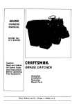
CRAFTSMAN
GRAS CATCH
#J
Assembly
installation
Operation
Repair Parts
Sears,
Roebuck
and Co., Chicago,
IL 60684
U.S.A.
CONGRATULATIONS
on your purchase of a Sears Craftsman
Grass Catcher Attachment.
It has been designed, engineered
and manufactured
to give you the best possible dependability
and performance.
Should you experience any problem
you cannot easily remedy, please contact your nearest Sears Service Department.
They have competent,
well-trained
technicians
and the proper tools to repair this unit.
Please read and retain this manual. The instructions will enable you to assemble, operate, and maintain your Craftsman
Grass Catcher properly. Always observe the "RULES FOR SAFE OPERATION".
FULL ONE YEAR WARRANTY
ON CRAFTSMAN
GRASS CATCHER ATTACHMENT
(EXCLUDING
BLADE(S) AND BLADE ADAPTER(S)
For one year from the date of purchase, when this grass catcher attachment
lubricated according to the operating and maintenance instructions in the owner's
repair free of charge any defect in material or workmanship.
This warranty excludes blade(s) and blade adapter(s),
ing normal use.
This warranty
which are expendable
is maintained and
manual, Sears will
and become worn dur-
does not cover:
- repairs necessary because of operator abuse or negligence, including the failure
to maintain the equipment according to instructions contained in the owner's
manual; and
- grass catcher attachments used for commercial or rental purposes.
WARRANTY
SERVICE IS AVAILABLE
BY CONTACTING
THE NEAREST SEARS SERVICE
CENTER/DEPARTMENT IN THE UNITED STATES. This warranty applies only while this product is
in use in the United States.
This warranty gives you specific Iegal rights, and you may also have other rights which vary from
state to state.
SEARS, ROEBUCK AND CO., Dept. 6981731A
Sears Tower,
Chicago,
IL 60684
TABLE OF CONTENTS
WARRANTY ...............................................
RULES FOR SAFE OPERATION .......................................
ASSEMBLY - MOWER ..............................................
ASSEMBLY - GRASS CATCHER ........................................
OPERATION ....................................................
MAINTENANCE ..................................................
STORAGE ......................................................
REPAIR PARTS ........................
: ..........................
2
3
4
7
11
12
12
14
RULES
1.
2
3
4
5
6
7
8
9,
10.
11.
12.
13,
14,
15,
16.
17.
18,
19.
20.
2 t,
22.
23,
FOR SAFE
Know the controls
and how to stop quickly,
READ THIS
OPERATOR'S
MANUAL
and instructions
furnished
with
your tractor.
Do not allow children to operate the machine,
Do not allow
adults to operate it without
proper instruction.
Do not carry passengers.
Do not mow when children and
others are around.
Always wear substantial
footwear.
Do not wear loose fitting clothing
that could get caught in moving
parts,
Keep your eyes and mind on your tractor,
mower and the
area being cut. Do not let other interests
distract
you.
Do not attempt
to operate
your tractor
or mower
when
not [n the drivers
seat.
Always
get on or off your tractor
from the operator's
left
hand side.
Clear the work area of objects
(wire, rocks, etc.) which
might be picked
up and thrown.
Disengage
all attachment
clutches
and return gear shift
control to neutral
before attempting
to start the engine.
Disengage
power ,to attachments
and stop the engine
before leaving the operator's
position.
Disengage
power to mower,
stop the engine and disconnect spark plug wire(s) from spark plug(s) before cleaning, making an adjustment
or repair.
Disengage
power to attachments
when transporting
or not
in1Jse.
Take all possible precautions
when leaving the vehicle unattended,
Disengage
the power-take-off,
lower the attachments,
return gear shift control
lever to neutral,
set
the parking brake, stop the engine and remove
the key,
Do not stop
or start
suddenly
when
going
uphill
or
downhill.
Mow
up and down
the face of slopes
(not
greater than 15°); never across the face. Refer to sight
guide in tractor
manual.
Reduce speed on slopes and make turns gradually
to prevent tipping
or loss of control.
Exercise
extreme
caution
when changing
direction
on slopes.
While going up or down slopes choose a speed tow enough
to negotiate
the slope without
stopping.
To reduce speed,
move gear shift control
lever to neutral
position.
Never mow in wet or slippery grass, when traction
is unsure or at a speed which could cause a skid,
Stay alert for holes in the terrain and other hidden hazards.
Keep away from drop-offs.
Do not drive too close to creeks,
ditches
and public
highways.
Exercise special care when mowing
around fixed objects
in order to prevent
the blades from striking
them. Never
deliberatefy
run tractor or mower
into or over any foreign
objects,
Never shift gears until tractor
comes to a stop.
Never place hands or feet under the mower,
in discharge
chute or near any moving
parts whi_e tractor
or mower
are running.
Always
keep clear of discharge
chute.
Use care when pulling loads or using heavy equipment.
a, Use only approved
drawbar
hitch points.
b. Limit loads to those you can safely control.
c. Do not turn sharply.
Use care when backing,
d. Use counterweight
or wheel weights
when suggested
in the owner's
manual.
OPERATnON
24.
25.
26.
27.
28.
29,
30.
31.
32.
33.
34.
35.
36.
37.
3 8.
Watch out for traffic
when crossing
or near roadways.
When using any attachments,
never direct discharge
of
material
toward
bystanders
nor allow anyone
near the
vehicle
while in operation.
Handle gasoline
with care - it is highly flammable.
a. Use approved
gasoline
containers,
b. Never remove
the fuel cap of the fuel tank or add
gasoline to a running
or hot engine or an engine that
has not been allowed to cool for several minutes
after
running.
Never fill tank indoors,
always
clean up spilled gasoline.
c. Open doors if the engine is run in the garage - exhaust
fumes are dangerous.
Do not run theengine
indoors,
Keep the vehicle and attachments
in good operating
con-dition,
and keep safety devices
in pIace and working.
Keep all nuts, bolts and screws tight to be sure the equipment is in safe working
condition.
Never store the equipment
with gasoline
in the tank inside a building
where fumes may reach an open flame or
spark. Allow
the engine to cool before storing
in any
enclosure.
To reduce fire hazard, keep the engine free of grass, leaves
or excessive grease. Never attempt
to clean product while
engine is running.
Except for adjustments;
DO NOT operate
Engine if air
cleaner
or cover
directly
over carburetor
air intake is
removed.
Removal of such part could create a fire hazard.
Do not operate without
a muffler
or tamper with exhaust
system.
Damaged mufflers or spark arresters could create
a fire hazard. Inspect periodically
and replace if necessary,
The vehicle
and attachments
should be stopped
and inspected for damage after striking
a foreign object and the
damage should be repaired before restarting
and operating
the equipment.
Do not change the engine governor
settings
or overspeed
the engine;
severe damage
or injury may result.
When using the vehfcle with mower,
proceed
as follows;
a. Mow only in daylight
or in good artificial
light.
b. Shut the engine off when unclogging
chute.
c. Check the blade mounting
bolts for proper tightness
at frequent
intervals.
Do not operate
the mower
without
entire grass catcher, on mowers so equipped or the deflector
shield in place.
Disengage
power to mower before backing
up. Do not
mow in reverse unless absolutely
necessary
and then only after careful observation
of the entire area behind the
mower.
Under normal usage the grass catcher bag material is subject to deterioration
and wear. It should be checked
frequently
for bag replacement.
Replacement
bags should
be checked
to ensure
compliance
with
the original
manufacturer's
recommendations
or specificatfons.
LOOK FOR THIS SYMBOL TO POINT OUT IMPORTANT SAFETY PRECAUTIONS. IT MEANS -- ATTENTION! BECOME
ALERT! YOUR SAFETY IS INVOLVED.
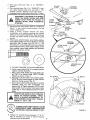
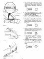
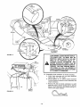
PARTSIDENTIFICATION
COVER
ELBOW
//€'
30 GALLON
CONTAINER
CHUTE
TUBE
ASSEMBLY
®
EXTENSION
CHUTE
ASSEMBLY
CHUTE LATCH
PIN
FIGURE 1
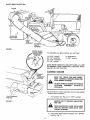
MOWER BLADE
CLUTCH LEVER
"DISENGAGED"
To assemble
(1)
(2)
(2)
(1}
POSITION
KEY
your
grass catcher
9/16" wrench
1/2" wrenches
7/16" wrenches
7/8" wrench
you
will need:
(1} screwdriver
(t) 3/8" wrench
NOTE: RIGHT HAND (R.H.) AND LEFT HAND (L.H.) ARE
DETERMINED FROM OPERATOR'S POSITION WHILE
SEA TED ON THE TRACTOR.
ASSEMBLY-MOWER
BRAKE
"ENGAGED"
READ THE "RULES FOR SAFE OPERATION" CARFEULLY BEFORE OPERATING
YOUR GRASS CATCHER,
DO NOT OPERATE MOWER WITH GRASS
CATCHER
ASSEMBLY
PARTIALLY
INSTALLED.
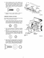
GEAR SHIFT
LEVER
All hardware for mower assembly found in bag labeled
"Mower Deck Hardware".
/"
"CLUTCH/BRAKE"
POSITION
1. Turn ignition
key (Fig. 2) to "OFF"
i
ill l
position.
i i
i
II'IH'I
REMOVE KEY TO PREVENT UNAUTHORIZED USE,
FIGURE 2
MAKE ABSOLUTELY SURE THE BLADES
AND ALL MOVING PARTS HAVE COMPLETELY STOPPED.
2 , Push c/utch-brake peda/ complete/y into "BRAKE"
position (Fig. 2).
-4-
3. Move gear shift lever {Fig. 2) to "NEUTRAL"
position.
4. Place parking brake (Fig. 2) in "ENGAGED" position. Raise parking brake lever and hold in "ENGAGED" position, Release ctutch-brake pedal.
5, Disengage mower blade clutch lever (Fig. 2 - Inset).
MOWER
MANDREL
i,
FROM THE SPARK PLUGIS) AND KEEP
WIRE(S) AWAY FROM THE PLUG(S) TO
PREVENT INJURY FROM ACCIDENTAL
STARTING.
LOWER
BLADE
•UPPER BLADE
SADDLE
ii
FLANGES
6. Remove mower from tractor. Refer to "To Remove
Mower" in your tractor owners manual. Turn the
mower upside down.
7. Using a 9/16"
wrench
remove
the bolts,
Iockwashers and washers securing the mower
blades to the mandrel assemblies. Save hardware
for later use when mower is used without grass
catcher.
8. Mount grass catcher blades, lower blade saddles,
upper blade saddles and mower blades to mandrel
assemblies (Fig, 3) using: two 3/8 - 24 x 1 - 3/4
hex bolts gr. 5, two Iockwashers and two washers
(shown full size below). Grass catcher blades, lower
blade saddles, upper blade saddles and hardware
furnished with grass catcher.
GRASS
CATCHER
BLADE
WASHER
_
LOCKWASH ER
HEX BOLT - GR. 5
FIGURE 3
HJlltlltnlnMIHrlIHtnlfD
L_I
a. For ease of assembly, turn mower upside down.
b. Return mower blade (Fig. 3) to original position
against mandrel assembly.
c. Place upper blade saddle and lower blade saddle (Fig. 3) on mower blade. NOTE: Position
flanges as shown in Fig. 3.
d. Place grass catcher blade in lower blade saddle.
NOTE: Be sure pointed edges of grass catcher
blade are facing upward (Fig. 3).
e . Secure grass catcher blade assembly to mandrel
assembly using hex bolt, Iockwasher
and
washer (Fig. 3). Tighten securely. NOTE: Lower
blade saddle must be seated inside upper blade
saddle (Fig. 3 -Inset). Repeat procedure for other
blade.
1'lit
'
_
a.H.
L.H.
BAFFLE
ii
ALWAYS USE GRADE 5 HEAT TREATED
BOLTS IN BLADES OCCASIONALLY TO
BOLTS TO ATTACH BLADES. CHECK
MAKE SURE BOLTS ARE TIGHT, TORQUE
BOLTS 27 - 35 FT. LBS.
i
i,
i
A GRADE 5 HEAT TREATED BOLT CAN BE
IDENTIFIED BY THREE LINES INDICATED
ON THE BOLT HEAD AS SHOWN AT LEFT.
9.
Using a 1/2" wrench remove hardware
"'A'" & "'B'"
(Fig. 4) securing
L.H. runner to mower
housing.
Hardware
may be discarded.
FIGURE 4
.5.
10. Place L.H, baffle (Fig. 4) on lip of mower housing.
Secure L.H. runner to L.H. baffle and mower housing using: two 5/16 carriage bolts and two 5/16
locknuts (shown full size below). NOTE: Do not
tighten. L.H, baffle and hardware furnished with
bagger.
1 1. Using a 1/2" wrench remove hardware "'D" (Fig.
5 - Inset) securing discharge guard to mower housing. Hardware may be discarded,
1 2, Using a 1/2"' wrench remove hardware "'A", "'B"
and "'C" (Fig, 6) securing R.H. runner to mower
housing. Hardware may be discarded.
R.H. FOOTREST
DISCHARGE
GUARD
1 3. Place R.H. baffle (Fig. 4) on lip of mower housing.
Secure R.H, runner to R,H. baffle and mower housing using: one 5/16 carriage bolt and one 5/16
locknut (shown full size below). NOTE: Do not
tighten. R.H, baffle and hardware furnished with
grass catcher.
MOWER
HOUSING
FIGURE 5
14. Secure L,H. baffle and R.H. baffle to mower housing using: four clamps, four 1/4 hex bolts and four
1/4 Iocknuts (shown futl size below). Clamps and
hardware furnished with grass catcher,
I tlll!!lllltllllJi
a.
Place clamps (Fig. 7) overholes
in L.H. and R, H.
baffles
(Fig, 7). Bolt heads to underside
of
mower
housing,
Tighten
securely.
NOTE:
Tighten
hardware
assembled
in step
10
securely.
1 5. Assemble
latch assembly to top of R.H. runner (Fig.
8) using: two 5/16 carriage
bolts and two 5/16
Iocknuts
(shown
full size below).
Bolt heads to
underside of mower housing, NOTE: Do not tighten.
Latch assembly and hardware
furnished
with grass
catcher,
FIGURE 6
©
CLAMPS
FIGURE 7
-6 -
1 6. Attach
discharge
guard
to latch
assembly
and
mower
housing
(Fig. 8) using two 5/16 carriage
bolts
and two
5/15
Iocknuts
(shown
furl size
below), Bolt heads to underside of mower housing.
Tighten securely,
Hardware
furnished
with grass
catcher.
NOTE: Tighten
hardware
assembled
in
steps 13 and 15.
©
R.H.
RUNNER
17. Reattach mower to tractor. Refer to "Mower
stallation'" in your tractor owners manual.
InFIGURE
ASSEMBLY-GRASS
8
CATCHER
All hardware for grass catcher assembly is found in bag
labeled "Mounting
Bracket Hardware".
1. Locate u-bolt in parts bag. Place two !/4
and two washers (shown full size below)
NOTE: Back nuts down the full length of
bolt and hardware furnished with grass
hex nuts
on u-bolt.
u-bolt. Ucatcher.
HEX NUTS
U-BO LT
WASHERS
2.
3.
Insert u-bolt through slot in drawbar
by reaching
from underneath
between
drawbar
and transaxle
(Fig. 9).
Place the rear mounting
bracket
(Fig. 9) on u-bolt
and secure with two washers and two I/4 Iocknuts
(shown full size below).
Tighten finger tight, Rear
mounting
bracket
and hardware
furnished
with
grass catcher.
DRAWBAR
1/4 LOCKNUTS
WASHER
•
318 LOCKNUT
_
REAR
'tOUNTING
BRACKET
SHOULDER
BOLT
©
4. Secure the rear mounting bracket to the drawbar
(Fig. 9) using: one shoulder bolt, one washer and
one 3/8 Iocknut (shown full size below). Tighten
securely. NOTE: Tighten hardware assembled in
step 3. Hardware furnished with grass catcher.
-7-
FIGURE 9
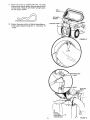
5. Assemble the support post to the rear mounting
bracket (Fig. 10) using support bracket pin and retainer spring. Retainer spring shown furl size below.
Support post, latch pin and retainer spring furnished with bagger.
SUPPORT
POST
f
6. Mount elbow support tube to support post (Fig. 1 1)
using: two 5/16 hex bolts and two 5/16 Iocknuts
{shown full size below}. NOTE: Position elbow support tube as shown in Fig. 1 1, Tighten securely,
Elbow support tube and hardware furnished with
bagger.
RETAINER
SPRING
REAR
MOUNTING
BRACKET
©
SUPPORT
BRACKET
PIN
7. Install end plug (Fig. 1 !) on elbow support tube. End
plug furnished with bagger.
8. Mount the elbow retainer and the elbow shield to
the elbow support tube (Fig. 1 1) using: two formed washers and two 5/16 Iocknuts {shown full size
below). NOTE: Do not tighten. Elbow retainer,
elbow shield and hardware furnished with bagger.
FIGURE 10
SUPPORT
POST
ELBOW
I
©
5116 HEX
BOLTS
.
FORMED WAI
ELBOW
SUPPORT
I
END PLUG
_" _
ELBOW SHIELD
TUBE
_"_
FIGURE
Slide elbow through elbow'retainer (Fig. t2 - Inset).
Secure elbow to elbow retainer using: two clips,
two screws, two washers and two acorn nuts.
NOTE: Mount clips in holes located 2 - I/2" from
edge of elbow. Hardware shown full size below,
Heads of screws and flat washers mount to the inside of elbow. Position clips with closed end of clip
facing tube opening as shown in Fig. 12 - Inset.
Tighten
securely.
NOTE: Tighten
hardware
assembled in step 8. Elbow and hardware furnished with grass catcher.
LOCKNUTS
11
10.
Flip seat
forward.
1111111111111111111]
Q
-8-
1 1, Mount top cover to support
post (Fig. 12) using
hinge pin and retainer spring. Retainer spring shown
full size below, Hinge pin and retainer spring furnished with grass catcher,
TOP
RETAINER
SPRING
1 2. Position the grass catcher container assemblies onto the support posts through the "'L " slots (Fig. 13
- Inset).
HINGE
SUPPORT POST
FIGURE
'r"L"
12
BRACKET
SLOT
POST
SUPPORT
POST
1G_RASS
CATCHER
CONTAINER _.---_
ASSEMBLIES [
FIGURE 13
ANDLE
CHUTE
_CHUTE
.EXTENSION E;
SHIELD
LATCH
ASSEMBLY
SPACER
_ASSEMBLY
ELBOW
CHUTE
TUBE
LATCH
.__PtN
HUTE
EXTENSION
ASSEMBLY
LATCH
ASSEMBLY
FIGURE
14
AS£EMBLY
i,n
JTE
EXTENSION
YOUR SPRING LOADED MOWER DEFLECTOR SHIELD (FIG, 14} MUST NOT BE
REMOVED. SIMPLY ROTATE IT UP AND
HOLD IN UP POSITION
WHILE ATTACHING
CHUTE EXTENSION.
THE
MOWER DEFLECTOR SHIELD CAN BE
RELEASED TO REST AGAINST CHUTE EXTENSION. THIS WILL ASSURE DEFLECTOR SHIELD IS STILL ON MOWER IF
CHUTE EXTENSION OF GRASS CATCHER
ATTACHMENT IS REMOVED.
TOP
\
1 3.
\
CONTA|NEPt _
FIGURE 15
ELBOW
SHIELD
-10-
Assemble
chute extension
to mower
housing.
a. Insert chute extension
pin into latch assembly
spacer (Fig. 14 - R.H. Inset).
b. Lift up slightly on L.H. side of chute extension
lining up spacers located on latch assembly and
chute extension.
c. Secure R.H side of chute extension
to latch
assembly
using: retainer spring (shown full size
below). Chute extension and retainer spring furnished with grass catcher.
d. Secure
L.H.
side
of chute
extension
to latch
DISENGAGE
MOWER WHEN CROSSING
GRAVEL SURFACES
AND ANY CONDITIONS
WHERE
THROWN
OBJECTS
COULD BE A HAZARD,
assembly using: latch pin and retainer spring. Retainer spring shown
full size below. Latch pin
and retainer spring furnished
with grass catcher.
DO NOT ATTEMPT
TO VACUUM
UP
CANS OR OTHER POTENTIALLY HAZARDOUS PROJECTILES.
r
1 4, Place chute tube (Fig, 14) in elbow. Place chute
tube over chute extension (Fig. 14) and secure by
pulling rubber latch on chute extension over latch
pin (Fig. 14 - Upper Inset) on chute tube.
I 5. Close top cover. NOTE: Be sure elbow shield is on
inside of top cover, Use latches to secure top cover
to pins of frame assemblies,
5,
6.
Avoid cutting wet grass or in the morning
while the
dew is stil! heavy. Grass clippings collected
under
these conditions
tend to be sticky and adhere to the
walls of the flow path causing clogging.
Keep clear grass catcher chute tube clean so that
clogging
can be detected.
DISENGAGE BLADES AND STOP ENGINE
BEFORE OPENING COVER.
OPERATION
IA ......... !°N
co..EoT
SPA.K
P.°O
W,.E,S,
SPA.K
P'°O,S,
i1,,
Follow the mower operation instructions
owners manual,
ii ,
,it
in your tractor
IA
CATCHER
INSTALLED.
,
ii ]ulll- 'H"lm'
ASSEMBLY
PARTIALLY
ii,
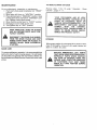
TIPS FOR IMPROVED BAGGING OPERATION:
1. Place throttle
control at full throttle,
2. Select a gear low enough to give good mower cutting performance,
good quality cut and good bagging performance.
NOTE: It may be necessary
to
overlap width of cut to suit your conditions.
3. If grass is extremely
tall, it should be mo wed twice.
The first time relatively
high, the second time to
desired height. NOTE: Use L.H. side of mower
for
trimming,
4. Plastic lawn bags can be inserted inside grass catcher containers
for ease of debris disposal.
MOWER. COVER
CLOSE
BEFORE
BEFORE
STARTING
KEEP CLEAR GRASS CATCHER CHUTE
TUBE CLEAN TO DETECT CLOGGING. IF
CLOGGING
OCCURS,
DISENGAGE
BLADES, SHIFT INTO NEUTRAL, ENGAGE
THE PARKING BRAKE AND SHUT OFF THE
ENGINE BEFORE REMOVING TUBE TO
CLEAR OBSTRUCTION.
When operating
your grass catcher on a lawn where
grass and leaf bagging equipment
has not been used, you
are picking up thatch and debris that has accumulated
for long periods of time. The amount
collected
and the
total time of operation
may be greater than you will experience
with regular use of your grass catcher,
iiii i,,
INSTALL
CONTAINERS
OPERATING.
i
If the grass catcher fails to pick up cut grass or leaves,
it is an indication
that clogging
has occurred
in the
system (See Step I be!ow) or that the grass catcher containers are full (See step 2 below).
1.
Stop tractor and mower and remove clogged grass.
Refer to "Caution"
above,
2. Disengage
blades, shift into neutral,
engage the
parking brake and stop the engine.
a. Unlatch cover (Fig. 15). Remove grass catcher
assemblies.
b, Remove
the grass
catchers
and replace
assemblies.
c. Close cover and latch.
NOTE:
If experiencing
abnormal
discharge
when
operating
mower without
grass catcher attachment
it
may be necessary
to remove grass catcher blades.
MAINTENANCE
TO REMOVE GRASS CATCHER
For any adjustment,
inspection
or maintenance:
1. Push clutch-brake
pedal completely
into "'BRAKE"
position.
2. Move gear shift lever to "'NEUTRAL"
position.
3. Place parking brake in "'ENGAGED"position.
Raise
parking brake lever and hold in "ENGA GED" position. Release clutch-brake
pedal.
4. Move throttle
control lever to "'SLOW"
position.
5. Disengage
mower
blade clutch lever.
6. Turn ignition key to "'OFF" position.
Reverse steps 1 thru 75 under "Assembly
Catcher", pages 7 _ 17.
............
BLADE CARE
,,i
i, ii
STORAGE
When grass catcher is to be stored for a period of time,
clean it thoroughly,
remove all dirt, grass, leaves, etc.
Store in a clean, dry place.
ii
To ensure satisfactory
operation, it is recommended
that
before the start of each mowing season, the old blades
be discarded and replaced
with new blades. Blades can
be purchased at all Sears Service Centers and most retail
stores,
,,,,,i,
YOUR CONTAINERS
ARE OF VERY
DURABLE MATERIAL, HOWEVER, IN THE
EVENT
OF EXCESSIVE
WEAR
OR
DAMAGE, REPLACE IMMEDIATELY, THE
REPLACEMENT
CONTAINER
SHOULD
COMPLY
WITH
THE
ORIGINAL
MANUFACTURED
SPECIFICATIONS
IN
ORDER TO INSURE PROPER PERFORMANCE AND PRODUCT SAFETY.
MAKE ABSOLUTELY SURE THE BLADES
AND ALL MOVING PARTS HAVE COMPLETELY STOPPED.
DISCONNECT THE SPARK PLUG WIRE(S)
FROM THE SPARK PLUG(S) AND KEEP
WIRE(S) AWAY FROM THE PLUG(S) TO
PREVENT INJURY FROM ACCIDENTAL
STARTING.
- Grass
,11
REPLACE IMMEDIATELY
ANY PARTS
THAT SHOW WEAR OR DETERIORATION,
ESPECIALLY PARTS WHICH CONTAIN
THE FLOW OF MATERIAL FROM THE
MOWER. ALSO, CHECK THE CONDITION
OF FASTENERS THAT KEEP THESE
PARTS IN A SAFE POSITION DURING
OPERATION.
SERVICE
NOTES
REPABR PARTS
CRAFTSMAN
GRASS CATCHER - 38" FOR StDE DISCHARGE MOWER--MODEL
NUMBER 917,249391
54
55
10
11
t7
/
62
A
B
C
53
34
@ 38
@ 35
M
O
_
38
27
E
E
REPAIR PARTS
CRAFTSMAN
KEY
NO.
GRASS CATCHER - 38" FOR SiDE DISCHARGE MOWER--MODEL
PART
NO.
1
2
3
4
5
6
7
8
9
10
11
12
13
14
15
16
17
18
19
20
2 1
22
23
24
_'5
26
27
28
29
30
31
32
33
34
35
36
3"7
DESCRIPTION
87065
86578
I04915X
87064
87067
87057
104389X
83553
86558
85902
86602
85903
86564
62361
86562
_
STD541437
86626
STD54!025
85723
87056
104387X
104415X
87054
85924
85937
85938
85936
85893
104418X
86543
26936
STD541010
77394
STD541431
57734
13328
E
F
KEY
NO.
Cover - Top
Bracket - Hinge
Strip - Foam
Strip - Foam
Container - 30 Gal.
Tube - Elbow Support
Plug - End
Clip - Elbow
Retainer - Elbow
Spring - Retainer
Pin - Hinge, Support Post
Spring - Retainer
Post - Support
Bolt - Shoulder
Bracket - Mountin_
Washer
*Nut - Lock 3r/8 "- T'6
U-Bolt t/4 - 20
*Nut - Hex 1/4 - 20
Washer - Flat 9132
Elbow
Pin - Latch, F_ear
Tube - Chute
Extension Chute
Latch Assembly - Chute, Rear
Baffle - R.H.
Baffle - L.H.
Clamp
Saddle - Lower Blade
Blade - Lower
Pin - Support Bracket
Screw - Truss Head 10-24 x .62
*Nut - Hex #10
Bolt - Hex 5/16 - 16 x 1 Gr. 5
*Nut - Lock 5/16 - 18
Washer, Formed
Screw - Truss Head 10-2_ x 5/8
G
H
38
_
43
J
K
38
39
40
41
42
43
44
45
46
47
48
49
50
51
52
53
54
55
56
57
58
59
'6 1
62
63
64
65
66
67
68
69
-----
59
_
40
_
40
64
_
35
_
40
PART
NO.
DESCRIPTION
STD541425
STD533110
76507
STD622512
85891
74316
STD551137
104406X
85925
STD523107
87091
85919
86987
STD551110
85463
71615
100225L
87061
87062
5080
2029J
12049
73501
86920
7206J
60867
57968
53847
67823
53059
65328
104419X
87068
*Nut - Lock 1/4 - 20
*Bolt - Carriage 5/16 - 18 x 1
Washer 11/32
_Bolt - Hex, 1/4 - 20 x 1 - 1/4
Bolt - Hex, 3/8 - 24 x 1 - 314 Gr. 5
Washer .406 x 1 x .1271.112
*Washer - Lock, 3/8
Baffle - Chute
Pin Assembly - Latch, Chute
*Bolt - Hex 5/16 - 18 x 314 Gr. 5
Latch Assembly
Handle - Tube, Chute
Saddle - Upper Blade
*WasherLock #10
Decal - Danger
Bolt - Hex 1/4 - 20 x 3/4
Latch - Hood
Assy. Bracket - Frame, R.H.
Assy. Bracket - Frame, L.H.
Washer, Lock No. 10
Nut - Weld
Washer, Flat
Screw, #10 - 24 x 1 - 1/4
Shield - Elbow
Spacer, Split
Acorn, Nut #10 - 24
Bolt - Hex 1/4 - 20 x 314
Washer
Nut - Lock 1/4 - 20
Bolt - Hex 1/4 - 20 x 1/2
Nut - Acorn 1/4 - 20
Bag - Trash, 30 Gal., 1.5 Mit.
Manual - Owners
*Standard
L
_ 59
@ 51
_33
NUMBER 917.249391
Hardware
-- Purchase Locally
M
_ 59
_ 59
@ 57
_65
_
68
66
_) 65
_
_
66
66
087
CRAFTSMAN
GRASS CATCH
OWNERS
MANUAL
The Model Number will be found on the Model Plate attached to the Support Post. Always provide the Model
Number when requesting service or repair parts for your
38" Craftsman Grass Catcher.
All parts listed herein may be ordered from any Sears Service Center/Departments
and most Sears stores.
HOW TO ORDER
REPAIR PARTS
WHEN ORDERING REPAIR PARTS. ALWAYS GIVE THE
FOLLOWING INFORMATION:
THE PART NUMBER
THE PART DESCRIPTION
THE MODEL NUMBER OF YOUR CRAFTSMAN
CATCHER
THE NAME OF MERCHANDISE
GRASS
Your Sears merchandise has added value when you consider Sears has service units nationwide staffed with
Sears trained technicians having the parts, tool and the
equipment to insure that we meet our pledge to you,
"WE Service What We Sell".
Sears, Roebuck and Co., Chicago,
IL 60684,
U.S,A.