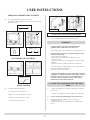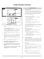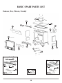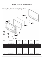
1
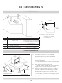
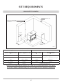
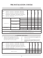
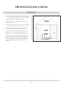
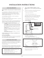
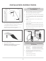
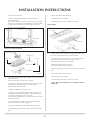
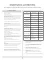
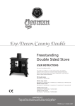
Exmoor/Exe/Devon/County
Freestanding Stove
INSTRUCTIONS FOR USE,
INSTALLATION AND SERVICING
For use in GB & IE (Great Britain and the Republic of Ireland).
This appliance has been certified for use in countries other than those
stated. To install this appliance in these countries, it is essential to obtain
the translated instructions and in some cases the appliance will require
modification. Contact Yeoman for further information.
Models: YM-W9001FL / YM-W9001LC / YM-W9001ERFL /
YM-W9001ERLC / YM-W9101FL / YM-W9101LC / YM-W9101ERFL /
YM-W9101ERLC / YM-W9102FL / YM-W9102LC / YM-W9102ERFL /
YM-W9102ERLC / YM-W9201FL / YM-W9201LC / YM-W9201HC /
YM-W9201ERFL / YM-W9201ERLC / YM-W9201ERHC /
YM-W9202FL / YM-W9202LC / YM-W9202HC / YM-W9202ERFL /
YM-W9202ERLC / YM-W9202ERHC / YM-W9301FL / YM-W9301LC /
YM-W9301HC / YM-W9302FL / YM-W9302LC / YM-W9302HC
IMPORTANT
This appliance will become hot whilst in operation, it is therefore recommended that a suitable guard should be used for the protection of young
children, the elderly or infirm. Do not attempt to burn rubbish in this appliance.
Please read these Instructions carefully before installation or use.
Keep them in a safe place for future reference and when servicing the fire.
The commissioning sheet found on page 3 of these instructions should be completed by the Installer.
PM306 Issue 2 (May 2010)
COVERING THE FOLLOWING MODELs:
YM-W9001FL / YM-W9001LC / YM-W9001ERFL / YM-W9001ERLC / YM-W9101FL / YM-W9101LC / YM-W9101ERFL /YM-W9101ERLC / YM-W9102FL/YM-W9102LC / YM-W9102ERFL /YM-W9102ERLC / YM-W9201FL / YM-W9201LC / YM-W9201HC / YM-W9201ERFL / YM-W9201ERLC /YM-W9201ERHC / YM-W9202FL / YM-W9202LC / YM-W9202HC / YM-W9202ERFL / YM-W9202ERLC/
YM-W9202ERHC / YM-W9301FL / YM-W9301LC / YM-W9301HC / YM-W9302FL / YM-W9302LC / YM-W9302HC
APPLIANCE COMMISSIONING CHECKLIST 3
COMMISSIONING
23
USER INSTRUCTIONS
MAINTENANCE & SERVICING
24
General Points
Using the Appliance for the first time
Recommended Fuels
Lighting the appliance
Running the appliance
Burning Tips
Ash Removal
Extended burning
Over-Firing
Chimney Fire General Cleaning
Cleaning Glass
Chimney Sweeping
Care of Stove
Seasonal Use
Troubleshooting Tips
INSTALLATION INSTRUCTIONS
4
4
5
6
6
7
8
9
9
9
9
10
10
10
10
11
11
Annual Service
Removal of Log Guard
Removal of Fire Brick
Removal of Baffle
Removal of multi-fuel grate
Fitting a New Door Glass
Fitting a New Door Seal
Adjusting Door Hinges
Adjusting Door Catch
24
25
25
25
25
25
26
26
26
BASIC SPARE PARTS LIST
27
SERVICE RECORDS
28
EC DECLARATION OF CONFORMITY
29
12
Technical Specifications
12
Standard Features
12
Packing List
12
Dimensions
13
SITE REQUIREMENTS
Flue & Chimney
Flue exit positions
Hearth Dimensions
Walls Next to Hearth
PRE-INSTALLATION
14
14
15
15
16
17
Ventilation
Additional Ventilation
17
18
INSTALLATION
19
Legal Requirements
Installing the Appliance
Rear Flue Installation
Top Flue Installation
Removal of Log Guard
Fitting & Removal of Baffles
Fitting & Removal of Fire Bricks
Fitting Multi-fuel kit to Wood Stove (optional)
19
19
19
20
20
21
21
21
This appliance has been approved by HETAS Ltd.
Warranty
Your Stovax/Yeoman retailer will provide you with a Two
Year Warranty for your new stove. They also provide a Five
Year Casting Warranty for all cast iron stoves and the cast
iron door of steel stoves. Full details of these warranties are
set out in our Instruction Manuals, which are also available
at www.stovax.com/www.yeoman-stove.co.uk.
2
APPLIANCE COMMISSIONING CHECKLIST
To assist us in any guarantee claim please complete the following information.
In the unlikely event of a problem, contact your installer or dealer for assistance:
Dealer appliance was purchased from
Name:......................................................................................................................................................................................
Address:...................................................................................................................................................................................
................................................................................................................................................................................................
Telephone number:..................................................................................................................................................................
Essential Information - MUST be completed
Date installed:..........................................................................................................................................................................
Model description:...................................................................................................................................................................
Serial number:..........................................................................................................................................................................
Installation Engineer
Company name:.......................................................................................................................................................................
Address:...................................................................................................................................................................................
................................................................................................................................................................................................
Telephone number:..................................................................................................................................................................
Commissioning Checks (to be completed and signed)
Is flue system correct for the appliance
YES
NO
Flue swept and soundness test complete
YES
NO
Smoke test completed on installed appliance
YES
NO
Spillage test completed
YES
NO
Use of appliance and operation of controls explained
YES
NO
Instruction book handed to customer
YES
NO
Clearance to combustible materials checked
YES
NO
Signature:........................................................................................ 3
Print name:................................................................
USER INSTRUCTIONS
1. GENERAL points
1.1
1.2
Before use of this appliance please read these
instructions fully.
All local regulations, including those referring to national
and European Standards need to be complied with when
installing the appliance.
1.3
Only use for domestic heating in accordance with these
operating instructions.
1.4
You must burn only approved fuels. Do not use with liquid
fuels or as an incinerator.
1.5
Appliance surfaces become very hot when in use. Use a
suitable fireguard if young children, elderly or infirm persons
are present.
Stovax offer firescreens, sparkguards and hearthgate systems
for protection*. Your Stovax dealer can advise you about
these products.
Data Plate
1.6
Do not place photographs, TV’s, paintings, porcelain or
other combustible items on the wall or near the appliance.
Exposure to hot temperatures will cause damage.
1.7
Do not place furniture or other items such as drying
clothing closer than 1m from the front of this appliance.
1.8
Extractor fans or cooker hoods must not be placed in the
same room or space as this can cause appliance to emit
fumes into the room.
1.9
Do not obstruct inside or outside ventilation required for
the safe use of this appliance.
AIR CONTROLS
Triple Air System
1.10 Do not make unauthorised changes to the appliance.
1.11 The chimney must be swept at least once a year.
See Section 13
1.12 Do not connect, or share, the same flue or chimney
system with another appliance.
SERIAL NUMBER
1.13 This number is required when ordering spare parts or
making warranty claims. It is found on the data plate,
located on the underside of the ashlip plate.
PR7517
*In the U.K: These products must conform to BS 6539,
Fireguards for use with solid fuel appliances.
If appliance is operating unattended they must conform to
BS 3248
4
This appliance has a triple air system providing cleaner
burning, and greater efficiency and control, Diagram 2.
1) Airwash - air drawn over the window cleans the glass.
The source of Primary Combustion air when burning wood.
2) Primary Air - for use with solid fuel and initially with
wood fires.
3) Secondary air - preheated through a heat exchanger to
combust unburned hydrocarbons, providing a cleaner and
more efficient burn.
USER INSTRUCTIONS
AIRWASH & PRIMARY AIR CONTROLS
1.14 Use a gloved hand to operate air controls.
The opposite end of the door tool can be used to operate
Airwash controls.
Open
Open
Airwash Control
Open
Close
Airwash Control
1 Door
PR7522
2 Door
PR7523
Airwash Control
DO NOT OPEN THE DOOR WITH BARE HANDS
1.16 To close the door follow the process in reverse.
WARNING
PR7518
Primary Air Control
Primary Air Control
Single Door
Primary Control
PR7519
Two Door
Primary Control
Open
Open
Close
Open
Properly installed, operated and maintained this
appliance will not emit fumes into the room.
Occasional fumes from de-ashing and refuelling may occur.
Persistent fume emission is potentially dangerous and
must not be tolerated.
If fume emission does persist:
• Open doors and windows to ventilate the room
• Leave the room
• Allow fire to burn out or safely dispose of fuel from the
appliance
• Check for chimney blockage and clean if required
SECONDARY AIR CONTROLS
• Do not attempt to relight until the cause of the emission
has been identified and corrected
If necessary seek expert advice.
Secondary Air Control
PR7520
Secondary Air Control
PR7521
• All open flued appliances can be affected by temporary
atmospheric conditions which may allow fumes to enter
the house. Because of this it is recommended that an
electronic carbon monoxide detector conforming to
BSEN50291 be fitted and maintained.
Single & Two Door
Secondary Control
Close
Open
2. USING THE Appliance FOR THE FIRST
TIME
DOOR HANDLE
1.15 To Open and Close the door:
• Drop door tool over knob to fit
• Rotate 1/2 turn anti-clockwise to open
• Rotate 1/2 turn clockwise to close
• Lift up door tool to remove
2.1
To allow the appliance to settle and fixing glues and paint
to fully cure:
• Operate the appliance at a low output for first few days
2.2
Do not touch the paint during the first period of use.
2.3
During this time the appliance may give off some
unpleasant odours:
• Keep the room well ventilated to avoid a build-up of fumes
5
USER INSTRUCTIONS
3.3
3. RECOMMENDED FUELS
3.1
Wood Logs:
• Burn only seasoned timber with a moisture content of less
than 20%
Wood Length
Appliance
Wood Length
Exmoor
250mm
Exe
300mm
Devon
350mm
County
400mm
• Dry cut wood for 12 to 18 months before use
Poor quality timber:
— Causes low combustion efficiency
— Produces harmful condensation
— Reduces effectiveness of the airwash and life of the
appliance
Do not burn construction timber, painted, impregnated /
treated wood, manufactured board products or pallet
wood.
3.2
Solid fuel:
To burn smokeless fuels it is required to fit a cast iron multi
fuel kit. This kit also allows the efficient combustion of
wood.
Fuel Consumption
Kg/Hour
Wood
(300mm long)
Kg/Hour
Briquette
Smokeless Fuel
Exmoor
1.7
0.7
Exe
1.7
0.7
Devon
2.7
1.5
3.9
2.1
3.4
For advice on suitable solid fuels:*
• Contact your local approved coal merchant
A number of factors can affect the performance of the
appliance. See Section 6 'Burning Tips' for details.
4. Lighting the appliance
4.1
For best results:
• Set air controls, See Diagram 5
Air Wash:
Fully Open
Secondary Air:
Fully Open
Multi-fuel kit part numbers:
Description
County
Fuel consumption.
As tested at nominal heat output to the requirements of EN
13240: 2001 for intermittent operation:
Stove
Part No.
Exmoor
YM-A9040CE
Exe
YM-A9140CE
Devon
YM-A9240CE
County
YM-A9340CE
Primary Air:
25% Open
Air Wash:
Fully Open
Only for use with recommended fuels, see Installation
Instructions for full fitting details.
Secondary Air:
Fully Open
• Burn only anthracite or manufactured briquette smokeless
fuels listed as suitable for use with closed heating appliances
Do not burn bituminous coal, ‘petro-coke’ or other
petroleum based fuels as this will invalidate the product
guarantee.
*In the U.K:
• Ring the Solid Fuel Association advice line on
0845 601 4406 for details
• Visit their web site at www.solidfuel.co.uk
6
Primary Air:
25% Open
• Place firelighters or paper and dry kindling wood on the
grate
• Light the paper or firelighters, See Diagram 6
USER INSTRUCTIONS
5. Running The appliance
5.1
Burning Wood (with or without Multi-fuel kit fitted):
• Leave the Secondary Air fully open
• Close the Primary air control and use the Airwash to
control the burn rate when appliance is at operating
temperature, see Diagram 8
Air Wash: Fully Open
• Leave the door slightly open as the fire establishes and
the glass warms to avoid the build-up of condensation
• Add larger pieces of wood
Too many logs may smother the fire.
Do not load fuel above the log guard and the secondary
combustion holes at the back of the firebox.
See Diagram 7
Primary Air:
Closed
Secondary Air:
Fully Open
Air Wash: Fully Open
Secondary Combustion holes
Primary Air:
Closed
Log Guard
Secondary Air:
Fully Open
PR8252
• Close the door
Do not leave the door open as this could over-fire and
damage the appliance.
7
• Wood burns best on a bed of ash
• Rake the embers evenly over the fire bed and open the
Airwash control fully for a few minutes before re-fuelling
5.2
Burn new logs at high output for a few minutes before
adjusting the Airwash control. Refuel little and often for
clean, efficient burning.
5.3
Experience establishes settings to suit personal preferences.
5.4
Do not burn large amounts of fuel with the Airwash control
closed for long periods of time. This reduces the glass
cleaning effect and causes tars and creosotes to build-up in
the appliance and flue system.
5.5
When in use, burning the appliance at high output for a
short period also reduces tars and creosote.
5.6
Burning Solid fuel (with Multi-fuel kit fitted):
• Set air controls, See Diagram 9
• To burn solid fuel efficiently it is best to control the
combustion using the Primary air control only
USER INSTRUCTIONS
6. burning tips
Air Wash:
25% Open
6.1
Fuel Quality (Wood)
Use wood with a moisture content of less than 20%.
Seasoned logs have the bark beginning to lift and peel away
and cracks radiating from the centre. They feel lighter than
fresh cut wood of a similar size and sound hollow when
struck against each other. Logs should not feel damp or
have moss and fungal growths.
Symptoms related to wet wood:
— Difficulty starting and keeping a fire burning well
— Smoke and small flames
— Dirty glass and/or firebricks
— Rapid creosote build-up in the chimney
— Low heat output
— Short burn times, excessive fuel consumption and
blue/grey smoke from the chimney
• Burn at high output at high output for a short period each
day to avoid large build-ups of tars and creosote within the
appliance and the flue system
• Use Stovax Protector chimney cleaner to reduce this
problem
Primary Air:
Adjust
Secondary Air:
Fully Closed
Air Wash:
25% Open
Primary Air:
Adjust
Secondary Air:
Fully Closed
5.7
De-ash the fire bed before re-fuelling, see Section 7 Ash
Removal.
• Open the Primary air control fully to establish a glowing
bed before adding new fuel
• Burn new fuel at high output for a few minutes before
adjusting the Primary air control to the desired setting
• Refuel little and often for clean, efficient burning.
5.8
Experience establishes control settings to suit personal
preferences
5.9
Do not burn large amounts of fuel with the Primary Air
Control on low settings for long periods of time. This
reduces the glass cleaning effect of the air wash and causes
tars and creosotes to build-up in the appliance and flue
system.
6.2
6.3
Air inlets puffing smoke
Combustion gases build up in the firebox and ignite as small
explosions, causing smoke to puff out of the air inlets and
other openings. This occurs if the air controls are shut soon
after adding new fuel to a very hot fire. Stop by opening the
air controls to increase combustion air and burning rate.
6.4
Flue Draught
The chimney has two main functions:
1) To safely remove the smoke, gases and fumes from the
house.
2) To provide a sufficient amount of draught (suction) in the
appliance ensuring the fire keeps burning.
Draught is caused by the rising hot air in the chimney when
the appliance is lit.
5.10 When in use, burning the appliance at high output for a
short period also reduces tars and creosote.
5.11 You must burn only anthracite or smokeless fuels
suitable for use in closed appliances.
5.12
Do not burn bituminous coal, ‘petro-coke’ or other
petroleum based fuels as this invalidates the product
guarantee.
Do not load fuel above the log guard and the secondary
combustion inlets at the back of the firebox.
See Diagram 7
8
Fuel Quality (Solid Fuel)
• Use recommended solid fuels approved for use with
closed appliances.
Symptoms related to unsuitable fuels include:
— Difficulty starting and keeping a fire burning well
— Smoke and small flames
— Dirty glass and/or fire bricks
— Short life span for grate, baffles and internal firebricks
— Permanent staining of glass
Symptoms of poor performance related to flue draught
include:
— Excessive fuel consumption (high flue draught)
— Poor burning control, overheating (high flue draught)
USER INSTRUCTIONS
— Wind noise from air controls (high flue draught)
— Difficulty getting a fire going and keeping it burning well
7. Ash removal
(low flue draught)
— Low heat output (low flue draught)
— Smoke entering room when doors opened (low flue
draught)
The construction, position, size and height of the chimney
all affect the performance of the flue draught.
Other factors effecting the flue draught include:
— Trees or other buildings nearby causing turbulence
— High and gusty winds
— Outside temperature
— Outside weather conditions
— Incorrect additional ventilation to building
— Blocked flue / chimney
For advice on the correction of persistent flue problems
consult a qualified solid fuel heating engineer before
continuing to use the appliance.
6.5
Weather conditions
The weather conditions outside the building can effect the
burning performance of the appliance. These could include:
Do not allow ash to build up in the appliance as it will
not burn properly and may cause damage.
7.1 Wood:
• Open the door
• Remove drop-in front plate, Diagram 10
10
PR7535
Weather Conditions
Problem
Effect
Windy days
Buildings/Obstacles
cause turbulent air
around chimney.
Smoky Appliance
Calm days
Oversized Chimney.
Smoky Appliance
Damp / Rainy days
Flue temperature
not hot enough.
Rain water inside
chimney.
Lighting and
burning problems
• Riddle the appliance using a poker or if a multi-fuel kit is
fitted move the riddling lever back and forth
•Remove ashpan and empty
Warning: Heat can remain in the ash long after use.
De-Ash at least once a week.
11
To reduce these problems:
• Use good quality kindling wood to start the fire
• Burn initially at a high temperature for a short period
• Fit a rain cowl to the chimney
Your installer should advise you on possible solutions.
If the appliance emits smoke into the room continuously:
• Close the air controls and allow the appliance to go out
• Ventilate the room to clear the fumes
• Leave the room
• Leave a thin layer of ash to start a new fire on
Do not re-light the appliance until the problem is solved
7.2
Smokeless fuels:
• De-Ash before filling with new fuel
Do not allow ash to build up on the underside of the
grate as this can cause premature failure.
• Pull the operating knob in and out rigorously using the
door handle tool
Do not use bare hands to operate the riddling system.
Ashpan tool
In the U.K:
* registered with HETAS (GB only)/INFO (Republic of
Ireland only)
** This should be done by a HETAS registered chimney
sweep, who will issue you with a certificate.
9
PR7536
USER INSTRUCTIONS
•Remove ashpan and empty
Warning: Heat can remain in the ash long after use. .
7.3
Use gloves, or place the ash into a Stovax Ash Caddy
(Stovax Part No. 4227)
7.4
Do not place hot ash in a bin made from plastic or any
other combustible material.
c) It is repaired as required before re-use. Use only
genuine Stovax replacement parts to keep your appliance in
safe and efficient working order.
11. GENERAL CLEANING
11.1 Clean and inspect your appliance regularly, especially in
periods of heavy use. Regular cleaning and maintenance
will help give many years of safe use.
8. EXTENDED burning
It is possible to get the appliance to burn for extended
periods of time.
In order to do this:
• Allow appliance to cool thoroughly to avoid risk of
burns.
• Remove the ash completely, See Section 7
• De-ash prior to final refuelling
• Set air controls to low combustion settings
This will blacken the glass over night but it will clear when
operated at high output for a short period.
• Check the internal components for damage; grates, bricks
and baffles. Do not use the appliance if any parts are
broken or damaged
• Check for obvious build up of soot, any ash or debris
above the flue baffle(s). Use a torch if necessary
• Use smokeless fuel or small, thick logs depending on fuel
desired
8.1
• If there are any signs of a build up of debris above the
flue baffle(s) either:
• Arrange for the chimney to be swept, See Section 13
• Remove the baffles and clear the debris, See Section 3 Installation Section
9. OVER-FIRING
9.1
Do not over-fill with fuel or use at maximum output for
long periods or over-firing can occur. If the flue pipe, flue
collar or top plate glow red the appliance is over-firing:
• Close the air controls to reduce the output
9.2
Over-firing can cause permanent damage to the appliance.
• Evacuate the building
• Call the fire brigade
• Do not re-enter the building until it is confirmed safe
b) The chimney system is inspected and swept by a
chimney sweep, confirming the system is structurally sound
and free from obstruction before re-use.**
In the U.K:
* This should be done by a HETAS registered chimney
sweep, who will issue you with a certificate.
• Keep the glass clean with correct use of the Airwash system
and good quality fuel
Sometimes additional cleaning may be required.
12.1
This can be done as follows:
• Allow appliance to cool fully
Do not clean hot glass.
• Use a soft cloth and Stovax Glass Cleaner
12.2 Before re-lighting the appliance:
• Dry the glass fully
10.2 Do not use the appliance after a chimney fire until:
a) It has been inspected by a registered installer,
confirming the appliance is safe to use*
Do not use aerosol sprays near an operating appliance
10.1 If a chimney fire occurs:
• Shut all air controls immediately
12. CLEANING GLASS
10. Chimney fire
• Check that the door(s) shut properly and creates an
effective seal
Leaking door seals prevent the appliance working properly.
12.3 Do not use abrasive cleaner or cleaning pads.
10
USER INSTRUCTIONS
13. CHIMNEY SWEEPING
13.1 To maintain safe and efficient use of the appliance the
chimney/flue must be inspected and swept at least once a
year by a qualified chimney sweep.*
If the appliance is used continuously throughout the year or
it is used to burn wood, more frequent sweeping is
recommended.
The best time to have the chimney swept is at the start of
the heating season.
The above applies even if burning smokeless fuels.
15. Seasonal use
13.2 The chimney, any connecting flue pipe and the appliance
flue ways if incorporated, must be regularly cleaned.
15.1 Clean and service the appliance if it is not used during the
warmer periods of the year as detailed in the Maintenance
and Servicing section
13.3 Ensure adequate access to cleaning doors where it is not
possible to sweep through the chimney.
15.2 Set the air controls 50% open to keep the appliance
ventilated and stop the build-up of any moisture inside.
13.4 If the appliance is believed to have previously served an
open fire the chimney must be swept a second time within
a month of regular use after installation.
15.3
14. Care of stove
16. Troubleshooting tips
Stovax has a range of cleaning and maintenance products and
accessories to keep your appliance in good working condition.
Your Stovax retailer can provide full details but here is a brief list of
useful items:
Product Code
Description
5039
Gas lighter
4052
Log basket
3042
Pipe Thermometer
3048
Wood sling - for easy carrying of logs
4027
Extra long protective gloves
5038
Hearthgate - 5 section (for areas 1780x610mm
4227
Ash caddy - 382x102x306mm
4228
Ash caddy - 446x102x306mm
4229
Ash caddy - 382x102x459mm
4230
Ash caddy - 637x127x408mm
4231
Ash caddy - 306x178x459mm
2091
Ashclean vacuum cleaner attachment
4232
Steel brush
Before re-lighting the appliance:
• Remove the baffles
• Clear any debris that may have accumulated
• Check the flue is clear of any blockages
16.1Stove glass blackening:
This has four possible causes:
1.
Incorrect use of airwash – See Sections 1, 4 and 5 for the
correct use of the air controls.
2.
Burning unseasoned wood – See Section 3 to identify
when wood is ready for burning.
3.
Stove operated at too low a temperature - good working
temperature is 300-500° F (120 – 250° C). A stove pipe
thermometer can identify this problem (Stovax part no
3046)
• Burn with the airwash control fully open for
approximately 20 minutes to cure this
The problem may be caused by damping your appliance
down overnight.
4.
Problems with the flue – in particular insufficient air pull.
If the flue is not working efficiently the glass can blacken. A
flue which has too much downdraft may be too short or
needs lining or has too many bends. This can also cause
blackening of your stove glass. Contact the installer or a flue
specialist for advice.
16.2 Riddling mechanism jamming:
This occurs when fine ash builds up under the riddling
mechanism preventing movement. To prevent this:
• Follow a regular cleaning routine for the inside of your
appliance
Your retailer can provide genuine spare parts such as replacement
glass, door sealing rope and fire bricks when required. An annual
service by a competent engineer is recommended to keep your
appliance in best possible condition.
11
USER INSTRUCTIONS
• Lift out the riddling mechanism and remove all ash
• Replace riddling mechanism when cleaning is complete
16.3 Glass cracking:
Do not over tighten the screws on the glass clips when
replacing the glass as this causes stress and the intense
temperature changes can cause the glass to crack. For
replacement glass contact your local Stovax dealer.
16.4 Appliance is producing tar:
This is identified by:
• A very strong pungent smell shortly after the appliance is
lit and heats up
• Glass blackening
• Thick, brown and sticky tar oozes from the pipe joints
This is caused by burning damp wood and burning your
appliance at too low a temperature;
• Use well seasoned wood and operate the appliance in the
ideal temperature range
Tar is a major cause of chimney fires - if you experience
problems with tar build up consult a chimney sweep before
continued use of your appliance.
Ideal working temperature range is 130°C and 240°C
(270°F – 465°F). Failing to close down the primary air
control once the appliance has heated up to this range may
cause the appliance to over-fire and to exceed the ideal
temperature range. Over-firing can cause permanent
damage to the appliance and invalidates your warranty.
16.5 In the unlikely event of a problem that cannot be solved
by these tips contact your installer or dealer for help.
12
TECHNICAL SPECIFICATION
YEOMAN EXMOOR/EXE/DEVON/COUNTY
4.9
4.9
9
13
Solid Fuel
kW
4.9
4.9
9
13
mm Wg
1.25
1.25
1.25
1.25
inch Wg
0.05
0.05
0.05
0.05
g/s
5.8
4.7
4.9
9.5
Solid Fuel
g/s
3.9
4.8
6.8
7.5
Wood
oC
338
394
426
340
Solid Fuel
oC
338
394
426
326
mm
125
150
150
150
inch
5
6
6
6
Kg
65
105
112
160
All fuels
Wood
Flue Outlet Size (Top/Rear Option)
Weight
Wood
Recommended Fuels
Solid Fuel
Seasoned wood (less than 20% moisture content)
Briquette smokeless fuel suitable for closed appliances
(Ancite-Phuracite-Taybrite-Homefire Ovals)
As tested to the requirements of EN 13240 for intermittent operation
STANDARD FEATURES
PACKING LIST
•
Primary air (under grate air for full multi-fuel use)
•
Instructions
•
Airwash (for wood burning / clean glass)
•
Guarantee card
•
Adjustable secondary air control (to ensure complete •
Pair leather gloves
burning of flue gases)
•
Door handle tool
Riddling grate system for clean de-ashing when fitted •
2 x Baffle extension tubes
with multi-fuel kit (excludes County models)
•
Cast flue spigot
•
Removable door handle tool
•
Cast flue blank
•
Top or rear flue exit option
•
Pack of fixings
•
Removable door cross option (2 door only)
•
Rose or plain primary air spinners (1 door only)
•
County
kW
Flue Draught at Nominal Heat Output
Flue Gas Temperature at Spigot / Socket
Devon
Wood
Nominal Heat Output
Flue Gas Mass Flow
Exe
Exmoor – YM-W9001FL / YM-W9001LC / YM-W9001ERFL / YMW9001ERLC
Exe –
YM-W9101FL / YM-W9101LC / YM-W9101ERFL / YMW9101ERLC
YM-W9102FL / YM-W9102LC / YM-W9102ERFL / YM-W9102ERLC
Devon –
YM-W9201FL / YM-W9201LC / YM-W9201HC / YM-W9201ERFL /
YM-W9201ERLC / YM-W9201ERHC / YM-W9202FL / YM-W9202LC /
YM-W9202HC / YM-W9202ERFL / YM-W9202ERLC / YM-W9202ERHC
County – YM-W9301FL / YM-W9301LC / YM-W9301HC / YM-W9302FL/
YM-W9302LC / YM-W9302HC
Exmoor
MODEL:
13
SITE REQUIREMENTS
YEOMAN STOVE DIMENSIONS
PR7509
Description
A
B
C
D
E
F
G
H (dia)
Exmoor FT
523
437
290
100
407
324
89
125
Exmoor LC
667
447
309
100
407
324
89
125
Exe FT
517
595
307
115
402
351
89
150
Exe LC
682
599
319
110
402
351
89
150
Devon FT
565
618
349
118
449
394
115
150
Devon LC
729
599
353
128
449
394
115
150
Devon HC
891
608
353
111
449
394
115
150
County FT
596
748
447
125
471
506
120
150
County LC
812
777
450
145
471
506
120
150
County HC
928
768
452
111
471
506
120
150
All dimensions in mm. (25.4 mm = 1”)
14
SITE REQUIREMENTS
1. FLUE & CHIMNEY
1.1
The flue or chimney system must be in good condition.
It must be inspected by a competent person and passed for
use with the appliance before installation
Products of combustion entering the room can cause
serious health risks.
1.2
You must check the following:
— The construction of the masonry chimneys, flue block
chimneys and connecting flue pipe system must meet the
requirements of the Building Regulations†
— A flexible flue liner system can be used if certified for
use with solid fuel systems and installation complies with
manufacturer’s instructions and Building Regulations.
The flue liner must be replaced when an appliance is
replaced unless proven to be recently installed and in good
condition.
— If it is necessary to fit a register plate it must conform to
the Building Regulations†
— The minimum height of the flue or chimney must be
4.5m from the hearth to the top of the flue, with no
horizontal sections, a maximum of 4 bends with angles of
less than 45 degrees
— Enure the connecting flue pipe it kept a suitable
distance from any combustible material and does not form
part of the supporting structure of the building
— Make provision to remove the appliance without the
need to dismantle the chimney
— Any existing flue must be confirmed as suitable for the
new intended use as defined in the Building Regulations
— The flue or chimney systems must be inspected and
swept to confirm the system is structurally sound and free
from obstructions**
— If the chimney is believe to have previously served an
open fire the chimney must be swept a second time within
a month of regular use after installation to clear any soots
falls that may occurred due to difference in combustion
levels.
— The flue exit from the building must comply with local
building control rules.†
— Do not connect or share the flue or chimney system
with another heating appliance
1.3
Do not connect to systems containing large voids or over
230mm square.
1.4
You must provide suitable access to enable the collection
and removal of debris.
15
1.5
You must be able to sweep and inspect the flue when the
appliance is installed.
1.6
You must check the flue draught with all windows and
doors closed and any extraction fans in this or adjoining
rooms running at maximum speed. (See next section for
additional ventilation requirements)
Max. Draught = 2.0mm Wg
Min. Draught = 1.0mm Wg
In the U.K:
*The design of the flue and chimney systems and products
used should meet the requirements of ADJ along with any
other relevant, National or European standards that may
apply. Products should be specified with regard to the type
of appliance, position within the building, fuels to be used
and appliance operating temperatures.
** This should be done by a HETAS registered chimney
sweep, who will issue you with a certificate.
† Building Regulations Document J
Flue Plate:
Where a hearth, fireplace, flue or chimney is provided or extended (including cases where a flue is provided as part of refurbishment work), information essential to the correct appliance and use of these should be
permanently posted in the building, to meet Requirement
J4 of the Building Regulations (England and Wales), F3.12
(Scotland).
† Building Regulations Document J
Additional:
A new factory made system that complies to EN 1856; Part 1
can be used providing installation is to the requirements of:
i) BS 7566 Parts 1 -4
ii) the manufacturer's instructions
iii) Building Regulations.
For a guide containing information on Chimneys and Flues contact: The British Flue & Chimney Manufacturers’ Association,
FETA
2 Waltham Court
Milley Lane
Hare Hatch
Reading
Berkshire RG10 9TH
Tel: 0118 9403416
e-mail: [email protected]
SITE REQUIREMENTS
1. FLUE EXIT POSITIONS
Terminal
Flue
Vertical
Measurement
Horizontal
Measurement
150mm
max
Insulation
Adjacent
Building
The vertical measurement is the lowest from either the
point of discharge or 150mm above insulation.
IMPORTANT: Seek specialist
advice if installing in a dwelling
with a thatched roof
Position On Roof
Minimum Clearances
A
On ridge or within 600mm
600mm above ridge
B
Elsewhere on roof
2300mm horizontally from roof surface and:
a) 1000mm above highest point of flue exit
from roof or
b) as high as the ridge
C
On pitched, within 2300mm horizontally to
openable window, dormer
1000mm above top of opening
D
Within 2300mm of another building
600mm above top of building
2. HEARTH DIMENSIONS
2.1
The appliance must stand on a non-combustible
constructional hearth which is at least 125mm thick with
the minimum dimensions as shown in the diagram
opposite.
2.2
The building must have a suitable load-bearing capacity for
the hearth and appliance.
• Consult a structural engineer for advice before proceeding
2.3 When fitting into an existing hearth check:
• That the appliance complies with current construction
regulations and is at least the minimum sizes shown
150mm
minimum
225mm
minimum
Constructional Hearth
840mm minimum
2.4
If there is no existing fireplace or chimney it is possible to
construct a suitable non-combustible housing and hearth
setting. The flue must be installed in accordance with all
local and national regulations and current rules in force .
• Check if adding a new chimney to your property requires
planning permission
150mm
minimum
150mm
minimum
Constructional Hearth
840mm minimum
PR7510
16
SITE REQUIREMENTS
WALLS NEXT TO HEARTH
Thickness W
Solid, non-combustible
material e.g. masonry
or concrete
H
C
150mm
minimum
C
150mm
minimum
PR7511
Position of Appliance & Hearth in relation to walls
Requirement for the walls
Distance of hearth from wall
'C'
Distance of Appliance to wall
Min thickness of Wall
'W'
Min height of wall
'H'
0mm
0mm - 50mm
200mm
0mm
51mm - 300mm
75mm
Height of appliance + 300mm
Or
1200mm from the hearth (take largest
dimension)
0 - 150mm
150mm +
75mm
1200mm
150mm +
300mm +
No Minimum Requirement
Suitable clearance should be allowed around the stove to enable the correct fitting and maintenance of the appliance.
Any clearances should be confirmed by making a site survey and a physical check of wall thickness and dimensions.
17
PRE-INSTALLATION CHECKS
1. FLUES
Without flue liner Round
(diameter)
Flue/Chimney
Devon
Exe
mm
150
150
150
150
inch
6
6
6
6
mm
135
135
135
135
inch
51/2
51/2
51/2
51/2
With liner or Factory made
system (diameter)
mm
†150
150
150
150
installed in accordance with manufacturer's instructions
inch
†6
6
6
6
metre
4.5
4.5
4.5
4.5
feet
15
15
15
15
Without flue liner system
Square (diameter)
Flue/Chimney Size
Exmoor
Exmoor – YM-W9001FL / YM-W9001LC / YM-W9001ERFL / YMW9001ERLC
Exe –
YM-W9101FL / YM-W9101LC / YM-W9101ERFL / YMW9101ERLC
YM-W9102FL / YM-W9102LC / YM-W9102ERFL / YM-W9102ERLC
Devon –
YM-W9201FL / YM-W9201LC / YM-W9201HC / YM-W9201ERFL /
YM-W9201ERLC / YM-W9201ERHC / YM-W9202FL / YM-W9202LC /
YM-W9202HC / YM-W9202ERFL / YM-W9202ERLC / YM-W9202ERHC
County – YM-W9301FL / YM-W9301LC / YM-W9301HC / YM-W9302FL/
YM-W9302LC / YM-W9302HC
County
MODEL:
All products
(*minimum height)
* When measured from the top of the stove to the top of the flue, with no
horizontal sections and a maximum of 4 bends with angles of less than 45o
†May be 125mm (5") if only burning low volatiles (smokeless) fuels approved for use in Smoke Control Areas.
See web sit http://uksmokecontrolareas.co.uk for more information about approved fuel
2. ADDITIONAL VENTILATION
Extractor fans or cooker hoods must not be placed in the
same room or space as this can cause the appliance to emit
fumes into the room.
2.3
If any of these checks reveal problems do not proceed
with the fitting of the appliance until they have been
rectified.
Additional Ventilation
18
Exmoor
MODEL:
Exmoor – YM-W9001FL / YM-W9001LC / YM-W9001ERFL / YMW9001ERLC
Exe –
YM-W9101FL / YM-W9101LC / YM-W9101ERFL / YMW9101ERLC
YM-W9102FL / YM-W9102LC / YM-W9102ERFL / YM-W9102ERLC
Devon –
YM-W9201FL / YM-W9201LC / YM-W9201HC / YM-W9201ERFL /
YM-W9201ERLC / YM-W9201ERHC / YM-W9202FL / YM-W9202LC /
YM-W9202HC / YM-W9202ERFL / YM-W9202ERLC / YM-W9202ERHC
County – YM-W9301FL / YM-W9301LC / YM-W9301HC / YM-W9302FL /
YM-W9302LC / YM-W9302HC
County
2.2
Devon
Additional ventilation is required to comply with the
requirements of the Building Regulations. This must be
provided using a permanently open air vent, of the size
listed, which is positioned so that it is not liable to be
blocked both inside and outside the building.
Exe
2.1
mm2
0
0
2200
4400
cm2
0
0
22
44
in2
0
0
3.41
6.82
PRE-INSTALLATION CHECKS
3. Ventilation
3.1
This appliance requires ventilation to supply combustion air.
Any room containing the appliance must have a permanent
air vent opening with a total free area of at least 550mm2
per kW of appliance rated output above 5kW.
3.2
Increase air supply provisions where a room contains
multiple appliances.
3.3
If vents open into adjoining rooms or spaces there must be
an air vent of at least the same size direct to the outside.
3.4
Permanent air vents should be non-adjustable and
positioned where they are unlikely to become blocked.
3.5
Site the vents where cold draught is unlikely to cause
discomfort. This can be avoided by placing vents near
ceilings or close to the appliance, see Diagram opposite.
3.6
If the appliance has a nominal input not exceeding 5.0 kW
it therefore does not normally require any additional
permanent ventilation. If, however, spillage is detected
when commissioning the fire, there may be insufficient
natural ventilation and additional ventilation may be
required.
19
INSTALLATION INSTRUCTIONS
Legal requirements
Before installation of this product please read these instructions
fully.
It is very important to understand the requirements of the national
Building Regulations and standards*, along with any local
regulations and working practices that may apply. Should any
conflict occur between these instructions and these regulations
then the regulations must apply.
Your local Building Control Office can advise regarding the
requirements of the regulations.
1.1
Take care when installing the appliance. Careless
handling and use of tools can damage the finish and/or
area.
1.2
Lift the stove into position on the prepared hearth area,
taking care not to damage the hearth finish.
• Choose top or rear flue exit:
• Fit flue collar and blanking plate to suit
• Attach flue collar to top or rear with hexagonal bolts
Note: The black allen screws should be used to fix the
collar/blanking plate visible on the flat top/canopy
The appliance must be fitted by a registered installer†, or approved
by your local building control officer.
Works must be carried out with care to meet the requirements of
Health and Safety‡ and comply with the Health and Safety rules,
and any new regulations introduced during the lifetime of these
instructions. Particular attention should be drawn to:
• Handling: The appliance is heavy. Adequate facilities
must be available for loading, unloading and site handling.
• Fire Cement: Some fire cement is caustic and must not
come into contact with the skin. Protective gloves must be
worn. Wash hands thoroughly with plenty of water after
contact with skin.
• Asbestos: This appliance contains no asbestos. If there is
the possibility of disturbing any asbestos in the course of
installation seek specialist guidance and use appropriate
equipment.
• Metal Parts: Take care when installing or servicing the
stove to avoid personal injury.
1.3
• Seal with fire cement if desired
• Secure blanking plate with clamping screws
Top flue installation
Flue Pipe 915mm (3ft)
Size
Stovax Part No.
5"
4502
6"
4602
Self Tapping Screw
Seal Flue Collar
with Fire Cement
A faulty installation can cause danger to the inhabitants and
structure of the building.
PR7514
For users of this appliance:
Your building insurance company may require you to inform them
that you have installed a new heating appliance. Check that your
cover is still valid after installing the appliance.
• Lift appliance into position
Take care not to damage the hearth finish.
• Level feet using adjustable bolts
• Connect appliance to the chimney using flue pipe
1. INSTALLING THE STOVE
Each installation is unique to the property so it is not possible to
give details to suit every setting. The installation must comply with
Building Regulations and be made using "best practice"
construction methods.
Many fireplace openings have a supporting lintel. Do not remove
without supporting the remaining structure of the building. Do not
support the structure with the appliance or the flue system.
AR8009
In the U.K:
* England and Wales – Document J / Scotland - Part F/
Document J (Republic of Ireland only)
** BS 8303, BS 6461, BS 7566
† Registered body: HETAS (GB only)/INFO (Eire)
‡ Health and Safety at Work Act 1974
20
• Secure pipe to flue collar with self tapping screw
• Seal the connecting joints with fire cement
The Flue must be installed in accordance with
manufacturers instructions.
INSTALLATION INSTRUCTIONS
Typical Top Flue Installation
Typical Rear Flue Installation
To chimney connection as
detailed in building regulations
To chimney connection as
detailed in building regulations
Elbow
135 Elbow
600mm minimum
1000mm maximum
unsupportable weight
Size
Stovax Part No.
5"
4512
6"
4612
600mm minimum
1000mm maximum
unsupportable weight
Flue Pipe 915mm (3ft)
Size
Stovax Part No.
5"
4512
6"
4612
Flue Pipe 915mm (3ft)
Size
Stovax Part No.
Size
Stovax Part No.
5"
4502
5"
4502
6"
4602
6"
4602
PR7515
1.3
PR7513
Rear flue installation
2. REMOVAL OF THE LOG GUARD
Self Tapping Screw
Tee
Size
Stovax Part No.
5"
4516
6"
4616
2.1
To remove the Log guard:
• Lift Log Guard clear of the supporting brackets
• Rotate to clear the sides of the door opening.
Cap
Seal Collar with Fire Cement
PR7512
• Insert a tee into the flue collar
The cap supplied with the tee is used as cleaning access.
• Lift appliance into position
Take care not to damage the hearth finish.
• Level feet using adjustable bolts
• Connect tee to the chimney using flue pipe
• Secure tee to the flue collar with self tapping screw
• Seal the connecting joints with fire cement
Do not use a 90˚ elbow to make this connection
The Flue must be installed in accordance with
manufacturers instructions.
PR7537
Do not use appliance without the log guard in position.
3. FITTING & Removal of THE BAFFLE
21
3.1
The appliance is fitted with a baffle in the top of the firebox
to maintain efficient combustion.
• Allow the appliance to cool fully before removing the
baffle system.
• Remove the Log Guard from the appliance to give access
to the firebox
INSTALLATION INSTRUCTIONS
4. FITTING AND REMOVAL OF
THE FIREBRICKS
Baffle Extension
Tubes
Support Pin
4.1
Remove the firebricks as part of the routine maintenance.
This can be carried out without the use of tools after
removing the log bar, drop in front and baffle.
4.2
Allow the appliance to cool fully before removing firebricks.
4.3
Take care when handling, as bricks can become fragile after
use. Life span depends on the type of fuels burnt and the
level of use.
Rear Lip
PR7525
3.2
The front lip of the baffle should point downwards.
• Lift the baffle and slide the two baffle extension tubes off
of the support pins on the sides of the firebox.
The baffle can now be lifted clear of the support pins and
rotated out through the front of the appliance
• Replace damaged bricks as soon as possible from your
dealer
4.4
To remove bricks:
• Remove the upper side bricks by sliding out from above
the grate supports
Wood versions have two lower side bricks. Remove in the
same manner as the upper bricks, below the grate supports.
Note: Chamfers are positioned against the appliance body
• Replace in reverse order
Log Guard
Upper Side
Bricks
Upper Side
Bricks
Front Lip
PR7526
3.3
Do not modify the baffle
3.4
Fitting is the reverse of the above
IMPORTANT: Ensure the Baffle Extension Tubes are
fitted correctly before using the appliance.
Lower bricks in
wood stove only
PR7527
5. FITTING & Removal of the riddling
mechanism
22
Exmoor M/F Kit - Exe M/F Kit-
Devon M/F Kit-
County M/F Kit-
YM-A9040CE
YM-A9140CE
YM-A9240CE
YM-A9340CE
fits
fits
fits
fits
all
all
all
all
Exmoor products
Exe products
Devon products
County products
5.1
The optional multi-fuel kit enables the burning of
manufactured smokeless fuels as listed in User Section,
Recommended Fuels.
• Remove the log guard if fitted
• Remove the drop in front plate
INSTALLATION INSTRUCTIONS
• Remove the fire bricks
• Place the ashpan under the grate
• Remove the blanking bolt that is fitted in the grate
operating rod hole
This is located on the front of the stove near the lower right
hand corner of the door (not applicable for County models).
To do this loosen the M8 nut on the inside of the stove.
• Refit the drop in front plate
• Check that the door closes and seals correctly
County Model
Rear Grate
Blanking Bolt
Front Grate
Exmoor, Exe & Devon Models
Ashpan
Centre Grate
5.3
• Place the rear grate in position on the steel runners as far
back as it will go against the rear steel chamber
• Place the front grate on the steel runners and locate the
back edge against the front edge of the rear grate
Ensure the grates sit flat on the supports.
• Refit the firebricks above the grate*
The reverse of the process of removal.
• Refit the log guard into slots in the front sides of the front
grate
• Place the ashpan under the grate
• Refit the drop in front plate
• Check that the door closes and seals correctly
* Note: The 2 lower firebricks are not required with the
riddling kit.
Operating Rod
Lock Nut
Main Grate
Riddling Sleeve
Operating Knob
Ashpan
5.2
PR7516
• Place the main grate into place on the steel runners in the
sides of the stove
Ensure that the grate sits flat on the supports.
• Remove the operating knob and nut from the end of the
rod and fit the operating rod to the centre grate by
positioning the rod from inside
• Slide the riddling sleeve over the rod
• Feed the operating rod through the hole in the front of
the appliance from inside the firebox, while dropping the
centre grate into position in the main grate.
Ensure that the riddling sleeve is located on the boss on the
inside of the carcass.
• Lock into position with the nut, and refit the operating
knob on the front face of the appliance
• Refit the firebricks above the sides of the main grate*
• Refit the log guard into slots in the front side of the main
grate
23
COMMISSIONING
COMMISSIONING
1.1
• Replace the firebricks, baffle, and log retainer
• Check the door alignment and catch operation, adjust if
required, see Maintenance & Servicing Section 8&9.
Adjusting Door hinges
• Check the soundness of door seals, castings and joints
• Check the operation of the air controls
1.2
Now carry out a final smoke draw test:
• Explain the requirement to use a suitable fireguard
when children, elderly or infirm persons are near the
appliance
• All open flued appliances can be affected by temporary
atmospheric conditions which may allow fumes to enter
the house. Because of this it is recommended that an
electronic carbon monoxide detector conforming to
BSEN50291 be fitted and maintained.
To commission:
• First warm the flue with a blowlamp, or similar, for about
10 minutes
• Place a smoke pellet on the centre of the grate, with the
air controls open
• Close the door
Smoke should now be drawn up the flue and be seen to
exit from the flue terminal
Data Plate
PR7517
• Complete test with all doors and windows closed in the
room where the appliance is fitted
• Record dealer/supplier details and installer details in
Instructions
• If there are any extractor fans in adjacent rooms, the test
must be repeated with the fans running on maximum and
interconnecting doors open
• Record serial number in page 3 of Instructions
This number is required when ordering spare parts and
making warranty claims
• Check the effect of ceiling fans during the test
• Give the copy of the Instructions to the customer
If the test fails, re-check the suitability of the flue system
and ventilation. An inadequate air supply to the room is
potentially dangerous.
• Light the appliance and slowly increase the temperature
to operating levels
• Ensure no combustion products enter the room
• Open the main fire door when the appliance reaches
operating condition and carry out a spillage test with a
smoke match or pellet around the door opening
1.3
If excessive spillage occurs:
• Allow the appliance to cool and re-check the flue system
and ventilation
1.4
Finally:
• Explain the cleaning and routine maintenance
requirements
• Explain the safe operation of the appliance and the use
of the controls to the user and the importance of only
using suitable fuels
24
MAINTENANCE and SERVICING
For a complete list of spare parts and accessories contact your Dealer or call 01392 474011
This is a list of the maintenance products you may need to use
1. ANNUAL SERVICE
1.1
At the end of the heating season strip, inspect and clean the
appliance as detailed:
• Allow appliance to cool
• Remove all of the following internal parts; drop in front,
log guard, baffle, firebricks. For Multi-fuel versions remove
the complete grate and ash pan.
See sections 2 - 5 on how to remove the log bar, baffles,
firebricks and grates. Take care handling firebricks, as they
can become fragile after a period of use.
Task
Product Name
Glass Cleaning
Stove glass cleaner 500ml – wipe on
Stove glass cleaner 500ml – Spray on
Preventing build-up Protector (15 sachets)
of creosote in flue Protector (1kg tub)
• Sweep the appliance at this point if it is required
• Vacuum clean any remaining ash and debris from the
inside of the appliance.
Stovax offer a filter/collection attachment for your vacuum
cleaner to protect it from fire ash. Ash Clean (Stovax Part
No. 2091).
Vacuum and brush the resulting debris from the appliance.
• Clean the grate parts with a wire brush, and check the
parts for any damage
• Replace any damaged parts
• Check and clean the firebricks with a soft brush
• Replace broken bricks
Some surface damage will occur during use. The life of the
bricks will depend on the type of fuels burnt and the level
of use. Damaged bricks should be replaced as soon as
possible.
• Re-fit cleaned internal parts
• Remove and fit new rope seals, See sections 6 & 7
• Clean the door glass using Stovax Glass cleaner and a soft
cloth
Do not use abrasive cleaners to remove tar or soot deposits
from the glass.
• Lightly oil the door catch mechanism and hinge pins
Avoid getting oil onto the door seals and glass.
To refresh painted finishes use Yeoman paint.
1.2
Use genuine Yeoman replacement parts to keep your
appliance in safe and efficient working order. Your local
Yeoman dealer can provide you with the parts you require.
4103
7002
7025
Fire Cement - 500g tub
Fire Cement - 600g cartridge
2020
2021
Repainting
Yeoman Black (400ml aerosol)
YM-V00971
Protecting
your hands
Door sealing rope
Glass sealing rope
Fixing door seal
Ash Clean
4111
Sealing Flue
pipe joints
Cleaning matt
black stoves
• Clean the internal surfaces of the appliance using a wire
brush and scraper as required
Stovax Code
number
Collodial black (85ml)
Heat resistant leather gloves
7000
YM-E00007
14mm Black rope seal –
(handy pack)
5000
14mm Black rope seal –
(25m reel)
4670
3mm Black rope seal –
(handy pack)
4975
3mm Black rope seal –
(25m reel)
4974
Thermic seal glue – (50ml bottle)
5037
Ash Clean vacuum
cleaner attachment
2091
These products, all available from your local Yeoman
dealer, along with regular maintenance and use of the
correct fuels, will help you to keep your stove in the best
possible condition.
1.3 If you require more information about Yeoman products
visit our web site www.yeoman-stoves.co.uk or www.
stovax.com.
1.4
Using the appliance for the first time:
• Burn at a low output for the first day of use
This allows the seals, fixing glues and paint to fully cure.
1.5
During this time the appliance may give off some
unpleasant odours:
• Keep the room well ventilated to avoid a build-up of
fumes.
1.6
25
Your Yeoman dealer can carry out service and maintenance.
MAINTENANCE and SERVICING
Fixing Screws (x8)
2. REMOVAL OF THE LOG GUARD
2.1
Fixing Clips (x8)
See Section 2 Fitting & Removal of Log Guard in Installation
section.
Glass (x2)
3. FITTING AND REMOVAL OF the BAFFLE
3.1
Glass Seal (3mm)
See Section 3 Fitting & Removal of The Baffle in Installation
section.
Door (x2)
4. FITTING AND REMOVAL OF FIREBRICKS
PR7529
2 Door
4.1
See Section 4 Fitting & Removal of Firebricks in Installation
section.
6.2
Using a screwdriver remove the glass clip fixing screws.
The old glass can then be lifted clear of the door. (Note
how the 3mm sealing rope is placed between the glass and
the door.) Remember to dispose of the old glass and rope
safely.
6.3
Clean, and re-paint, the rear of the door if required
ensuring all old glue is removed from rope seal channel.
Clean the screws with light oil and coat with high
temperature anti-seize grease, this will aid future removal.
6.4
Fit a new sealing rope between the new glass and the door,
and place the glass into position in the door. Place the glass
fixing clips into position and re-fix with the clean fixing
screws, tighten the screws evenly until the clips hold the
glass. Do not over tighten the clips as this could break
the glass.
6.5
Fit only Yeoman ceramic glass, which is suitable to use in
high temperature applications.
6.6
Using the stove with a damaged door glass could cause
dangerous fumes to enter the room, or the stove to overfire, resulting in damage.
5. FITTING AND REMOVAL OF the riddling mechanism
5.1
See Section 5 Fitting & Removal of The Riddling Mechanism
in Installation section.
6. FITTING A NEW DOOR GLASS
6.1
To maintain the safe use of your appliance you may need to
replace a damaged door glass. To complete this operation:
• Remove the door, by opening, removing the hinge pins
and lifting the door free of the hinge blocks
• Lay the door face down on a soft flat surface, to protect
the paintwork and glass
Fixing Screws (x4)
Fixing Clips (x4)
7. FITTING A NEW DOOR SEAL
Glass
7.1
To maintain the safe use of your stove you may need to
replace a damaged or worn door sealing rope. To complete
this operation, use this method.
7.2
Remove the door from the stove, by opening and lifting the
door free of the hinge pins. Then lie the door face down on
a soft flat surface, to protect the paintwork and glass.
Glass Seal (3mm)
Door
1 Door
PR7528
Seal 14mm
Joint
1 Door
26
PR7530
MAINTENANCE and SERVICING
8.3
Seal 14mm
Using a 13mm A/F spanner loosen the fixing nuts, as shown,
and reposition the hinge blocks to achieve a correct fit. This
may require a trial and error approach to find the correct
position.
9. ADJUSTING DOOR CATCH
(ALL MODELS)
9.1
Seal 12x3
PR7531
2 Door
7.3
Remove the old rope and scrape old glue from the locating
grooves. Clean the locating groove with a clean dry cloth to
remove all old dust and debris.
7.4
Squeeze a generous bead of fresh Stovax Thermic Seal glue
into the rope locating groove (part no. 5037). Press the new
Stovax rope into the locating groove, placing the joint in the
middle of the lower edge of the door (one door version
only).
7.5
Refit and close the door to apply pressure to new rope.
Leave the stove closed for at least 12 hours before lighting
the stove and use at a low output for approximately one
day. This allows the adhesive to bond fully.
7.6
Using the stove with a damaged door seal could cause
dangerous fumes to enter the room, or the stove to overfire, resulting in damage.
7.7
If you require help, your local Yeoman dealer will be able
to carry out all of your service and maintenance
requirements for a reasonable cost.
8. ADJUSTING DOOR HINGES
(EXMOOR MODELS ONLY)
8.1
To maintain the safe use of your Yeoman Exmoor stove, you
may need to adjust the door hinges to ensure safe correct
closing of the door. Complete this operation as follows.
8.2
Open the door to give access to the fixed part of the door
hinge as shown.
Fixing Nut
Fixing Nut
PR7532
27
To adjust the fit of the door catch rotate the door knob
clockwise to loosen the fit or anti-clockwise to tighten the
fit. This adjustment should be made in steps of one full turn
of the door knob. The flat edge of the door cam should be
parallel with the door opening on the stove body when the
door is open.
BASIC SPARE PARTS LIST
Exmoor, Exe, Devon, County
1
16
2
15
14
3
4
13
See Assembly
8
7
11
6
9
12
5
10
Exmoor, Exe & Devon
17
County only
18
19
21
20
24
22
23
25
13A1
13B
Exmoor only
28
23
22
BASIC SPARE PARTS LIST
Exmoor, Exe, Devon, County codes
Diagram
No
Description
Exmoor
Product Code
Exe
Product Code
Devon
Product Code
County
Product Code
1
Flue Spigot assembly
5" YM-YM74545
6" YM-YM00545
6" YM-YM00545
6" YM-YM00545
2
Top plate CE
YM-A9031FL
YM-A9131FL
YM-A9231FL
YM-A9331FL
3
Blanking plate
5" YM-YM74510
6" YM-YM00510
6" YM-YM00510
6" YM-YM00510
4
Baffle extension tube
YM-C00008
YM-C00008
YM-C00008
YM-C00008
5
Upper side firebrick CE
YM-C74080
YM-C81080
YM-C82080
SL24
6
Lower side firebrick CE (Wood only)
YM-C74081
YM-C81081
YM-C82081
YM-C05081
7
M8 blanking screw nut
YM-F00019
YM-F00019
YM-F00019
-
8
Blanking screw CE only
YM-F00018
YM-F00018
YM-F00018
-
9
Tertiary air control slider
YM-C74957CE
YM-C81957CE
YM-C82957CE
YM-C05957
10
Tertiary slider spacer
YM-C00960
YM-C00960
YM-C00960
YM-C00960
11
Log retaining bar
YM-YM74080
YM-YM81080
YM-YM81080
YM-YM05080
12
Drop-in front ash cover CE
YM-YA74422
YM-YA81422CE
YM-YA81422CE
YM-YA05422
13
Door Casting
See Door Assembly
See Door Assembly
See Door Assembly
See Door Assembly
13a
Door Eyebolt
YM-F00060
-
-
-
13b
Door hinge pin 5/6"
YM-F00106
-
-
-
14
Baffle plate CE
YM-C74007CE
YM-C81007CE
YM-C82007CE
YM-C05007CE
15
Top air slider
YM-YA74018
YM-YA81018CE
YM-YA81018CE
YM-YA05018
16
Airwash slider bolt
YM-B81309
YM-B81309
YM-B81309
YM-B81309
17
Cast centre grate CE
YM-YM74071
YM-YM81071
YM-YM81071
-
18
Cast main grate CE
YM-YM74070
YM-YM81070
YM-YM82070
-
19
Riddling rod CE
YM-C74070
YM-C74070
YM-C74070
-
20
Riddling rod spacer CE
YM-C74072
YM-C74072
YM-C74072
-
21
Riddling rod knob CE
YM-C00073
YM-C00073
YM-C00073
-
22
Ashpan
YM-YA74003
YM-YA81003CE
YM-YA81003CE
YM-YA05003CE
23
Ashpan Tool
YM-C00006
YM-C00006
YM-C00006
YM-C00006
24
Main grate front CE
-
YM-YM05070F
25
Main grate back CE
-
YM-YM05070B
n/a
Door hinge pin 5/6"
YM-F00106
YM-F00106
29
YM-F00106
YM-F00106
BASIC SPARE PARTS LIST
Exmoor, Exe, Devon, County Single Door
1
2
11
3
4
5
6
10
7
9
8
Diagram
No
Description
Exmoor
Product Code
Exe
Product Code
Devon
Product Code
County
Product Code
1
Glass clamp screw
YM-F00001
YM-F00001
YM-F00001
YM-F00001
2
Door Rope Seal Pack
5000
YM-E81001
YM-E81001
YM-E05002
3
Standard glass clamp
YM-C00353
YM-C00353
YM-YMC00353
YM-YMC00353
4
Door Glass
GL0242
GL0252
GL0252
GL0254
5
Spinner Bolt
YM-F00010
YM-F00010
YM-F00010
YM-F00010
6
Single Door Casting CE
YM-YM74906CE
YM-YM81906
YM-YM82906
YM-YM05906
7
Door cam m18CE
YM-B00030CE
YM-B00030CE
YM-B00030CE
YM-B00030CE
8
Spiral Pin 3 x 18mm
YM-F00004
YM-F00004
YM-F00004
YM-F00004
9
Black door knob
YM-C00328
YM-C00328
YM-C00328
YM-C00328
10
Primary air rose spinner
YM-YM74058
YM-YM74058
YM-YM74058
YM-YM74058
11
Door Hinge Pin 6/6"
YM-F00106
YM-F00106
YM-F00106
YM-F00106
30
BASIC SPARE PARTS LIST
Exe, Devon, County Double Door
1
2
21
3
19
18
4
5
17
16
7
15
6
8
14
13 12 11 10
9
Diagram
No
Description
Exe
Product Code
Devon
Product Code
County
Product Code
1
Glass clamp screw
YM-F00001
YM-F00001
YM-F00001
2
Door Rope Seal Pack
YM-E82002
YM-E82002
YM-E05002
3
Standard glass clamp
YM-C00353
YM-C00353
YM-C00353
4
Door Glass (6 sided)
GL0251
GL0251
GL0253
5
Twin Door Cross RH CE
YM-YM81001
YM-YM81001
YM-YM05001
6
Door cam m18CE
YM-B00030CE
YM-B00030CE
YM-B00030CE
7
Spiral Pin 3 x 18mm
YM-F00004
YM-F00004
YM-F00004
8
Black RH door knob
YM-C00228
YM-C00228
YM-C00228
9
Door casting RH CE
YM-YM81907
YM-YM81907
YM-YM05907
10
Air slider cover RH CE
YM-C81087
YM-C82087
-
11
Primary Air Slider plate RH CE
YM-A81057
YM-A82057
YM-C00057 (2 per stove)
12
Primary air slider spacer
YM-B00258
YM-B00258
YM-B00258
13
M5 x M25 penny washer
YM-F00068
YM-F00068
YM-F00068
14
Primary air slider knob
YM-B00158
YM-B00158
YM-B00158
15
Primary air slider spring
YM-F00258
YM-F00258
YM-F00258
16
Air Slider cover LH CE
YM-C81086
YM-C82087
-
17
Door hinge pin 5/6"
YM-F00106
YM-F00106
YM-F00106
18
Door casting LH CE
YM-YM81908
YM-YM81908
YM-YM05908
19
Black LH door knob
YM-C00128
YM-C00128
YM-C00128
20
LH Door knob bolt
YM-F00098
YM-F00098
YM-F00098
21
Twin Door Cross LH CE
YM-YM81101
YM-YM81101
YM-YM05101
31
SERVICE RECORDS
1st SERVICE
2nd SERVICE
Date of Service: . . . . . . . . . . . . . . . . . . . . . . . . . . . . . . . . . . . . . .
Date of Service: . . . . . . . . . . . . . . . . . . . . . . . . . . . . . . . . . . . . . .
Next Service Due: . . . . . . . . . . . . . . . . . . . . . . . . . . . . . . . . . . . .
Next Service Due: . . . . . . . . . . . . . . . . . . . . . . . . . . . . . . . . . . . .
Signed: . . . . . . . . . . . . . . . . . . . . . . . . . . . . . . . . . . . . . . . . . . . .
Signed: . . . . . . . . . . . . . . . . . . . . . . . . . . . . . . . . . . . . . . . . . . . .
Dealer’s Stamp/HETAS Registration Number
Dealer’s Stamp/HETAS Registration Number
3rd SERVICE
4th SERVICE
Date of Service: . . . . . . . . . . . . . . . . . . . . . . . . . . . . . . . . . . . . . .
Date of Service: . . . . . . . . . . . . . . . . . . . . . . . . . . . . . . . . . . . . . .
Next Service Due: . . . . . . . . . . . . . . . . . . . . . . . . . . . . . . . . . . . .
Next Service Due: . . . . . . . . . . . . . . . . . . . . . . . . . . . . . . . . . . . .
Signed: . . . . . . . . . . . . . . . . . . . . . . . . . . . . . . . . . . . . . . . . . . . .
Signed: . . . . . . . . . . . . . . . . . . . . . . . . . . . . . . . . . . . . . . . . . . . .
Dealer’s Stamp/HETAS Registration Number
Dealer’s Stamp/HETAS Registration Number
5th SERVICE
6th SERVICE
Date of Service: . . . . . . . . . . . . . . . . . . . . . . . . . . . . . . . . . . . . . .
Date of Service: . . . . . . . . . . . . . . . . . . . . . . . . . . . . . . . . . . . . . .
Next Service Due: . . . . . . . . . . . . . . . . . . . . . . . . . . . . . . . . . . . .
Next Service Due: . . . . . . . . . . . . . . . . . . . . . . . . . . . . . . . . . . . .
Signed: . . . . . . . . . . . . . . . . . . . . . . . . . . . . . . . . . . . . . . . . . . . .
Signed: . . . . . . . . . . . . . . . . . . . . . . . . . . . . . . . . . . . . . . . . . . . .
Dealer’s Stamp/HETAS Registration Number
Dealer’s Stamp/HETAS Registration Number
7th SERVICE
8th SERVICE
Date of Service: . . . . . . . . . . . . . . . . . . . . . . . . . . . . . . . . . . . . . .
Date of Service: . . . . . . . . . . . . . . . . . . . . . . . . . . . . . . . . . . . . . .
Next Service Due: . . . . . . . . . . . . . . . . . . . . . . . . . . . . . . . . . . . .
Next Service Due: . . . . . . . . . . . . . . . . . . . . . . . . . . . . . . . . . . . .
Signed: . . . . . . . . . . . . . . . . . . . . . . . . . . . . . . . . . . . . . . . . . . . .
Signed: . . . . . . . . . . . . . . . . . . . . . . . . . . . . . . . . . . . . . . . . . . . .
Dealer’s Stamp/HETAS Registration Number
Dealer’s Stamp/HETAS Registration Number
9th SERVICE
10th SERVICE
Date of Service: . . . . . . . . . . . . . . . . . . . . . . . . . . . . . . . . . . . . . .
Date of Service: . . . . . . . . . . . . . . . . . . . . . . . . . . . . . . . . . . . . . .
Next Service Due: . . . . . . . . . . . . . . . . . . . . . . . . . . . . . . . . . . . .
Next Service Due: . . . . . . . . . . . . . . . . . . . . . . . . . . . . . . . . . . . .
Signed: . . . . . . . . . . . . . . . . . . . . . . . . . . . . . . . . . . . . . . . . . . . .
Signed: . . . . . . . . . . . . . . . . . . . . . . . . . . . . . . . . . . . . . . . . . . . .
Dealer’s Stamp/HETAS Registration Number
Dealer’s Stamp/HETAS Registration Number
32
33
Greg Taylor
Technical Director
34
A division of Stovax Ltd
Falcon Road, Sowton Industrial Estate, Exeter, Devon, England EX2 7LF
Tel: (01392) 474500 Fax: (01392) 219932
E-mail: [email protected] www.yeoman-stoves.co.uk