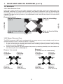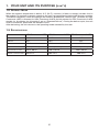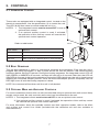
1
USER MANUAL
RESIDENTIAL USE ONLY
VB0175
HRV CONSTRUCTO 2.0ES*
HRV CONSTRUCTO 1.5ES*
* THESE PRODUCTS EARNED THE ENERGY STAR® BY MEETING STRICT ENERGY EFFICIENCY
GUIDELINES SET BY NATURAL RESOURCES CANADA AND THE US EPA. THEY MEET
ENERGY STAR REQUIREMENTS ONLY WHEN USED IN CANADA.
VB0170
ERV CONSTRUCTO 2.0ES
ADDRESS OF YOUR INSTALLER
20505 REV. 03
ABOUT THIS MANUAL / PRODUCT
The purpose of this manual is to help you with the use of your unit. Section 2 (Controls) shows you
how you can operate the unit in no time. Section 3 deals with maintenance and explains how to
maintain the unit to ensure maximum operation and performance. In Section 4 (Troubleshooting),
you will learn how to solve minor problems; plus other important information which we urge you to
read.
We welcome any suggestions you may have concerning this manual and/or the unit, and we would
appreciate hearing your comments on ways to better serve you. Please forward all correspondence
to us at the address indicated on the product’s registration card included with this manual.
This manual uses the following symbols to emphasize particular information:
! WARNING
Identifies an instruction which, if not followed, might cause serious personal
injuries including possibility of death.
CAUTION
Denotes an instruction which, if not followed, may severely damage the unit
and/or its components.
NOTE: Indicates supplementary information needed to fully complete an instruction.
Finally, we want to congratulate you on your purchase of this excellent unit which will allow you and
your family to enjoy fresh air throughout your home for years to come!
CAUTION
Some activities create dust or vapors which may damage your unit. You must
therefore turn off and unplug your unit in the following situations:
• Major renovation work
• Sanding (e.g. gypsum joints, etc.)
• Housing construction
• Varnishing
During very heavy snowstorms or rain with strong winds, the unit should also
be turned off to avoid problems caused by snow or rain entering the unit, even if
it is equipped with an anti-gust intake hood.
Power disturbances or very short power failures may cause the electronic
control microprocessor to malfunction. If it does, disconnect the power plug
from the outlet and wait approximately 30 seconds, then plug it back in to
resume operation.
CAUTION
When leaving the house for a long period of time (more than two weeks), a
responsible person should regularly check if the unit operates adequately. If
the ductwork runs through an unconditioned space (e.g.: attic), the unit must
operate continuously except when performing maintenance and/or repair. Also,
the ambient temperature of the house should never drop below 18°C (65°F). At
least once a year, the unit mechanical and electronic parts should be inspected
by qualified service personnel.
2
TABLE OF CONTENTS
1. YOUR UNIT AND ITS PURPOSE ........................................... 4-6
1.1 UNIT DESCRIPTION . . ...................................... ..............................4
1.2 PURPOSE OF THE VENTILATION SYSTEM ..................................................4
1.3 RECOVERY . . . . . . . . . . . ...................................................................5
1.3.1 HEAT RECOVERY CORE . . . . . . . . . . . . . . . . . . . . . . . . . . . . . . . . . . . . . . . . . . . . . . . . . . . . . . . . . . . . . . . . . . . . . 5
1.3.2 ENERGY RECOVERY CORE . . . . . . . . . . . . . . . . . . . . . . . . . . . . . . . . . . . . . . . . . . . . . . . . . . . . . . . . . . . . . . . . . . 5
1.4 DEFROST MODE . . . . . . ..................................... ..............................6
1.5 SPECIFICATIONS . . . . . . ...................................................................6
2. CONTROLS ..................................................................... 7
2.1 INTEGRATED CONTROL ...................................................................7
2.2 BOOT SEQUENCE . . . . . ..................................... ..............................7
2.3 OPTIONAL MAIN AND AUXILIARY CONTROLS ...............................................7
3. MAINTENANCE .............................................................. 8-9
3.1 EVERY THREE MONTHS .................................... ..............................8
3.2 ANNUAL MAINTENANCE (FALL) ............................................................9
3.2.1 HEAT RECOVERY CORE . . . . . . . . . . . . . . . . . . . . . . . . . . . . . . . . . . . . . . . . . . . . . . . . . . . . . . . . . . . . . . . . . . . . . 9
3.2.2 ENERGY RECOVERY CORE . . . . . . . . . . . . . . . . . . . . . . . . . . . . . . . . . . . . . . . . . . . . . . . . . . . . . . . . . . . . . . . . . . 9
4. TROUBLESHOOTING ....................................................... 10
3
1. YOUR UNIT AND ITS PURPOSE
1.1 UNIT DESCRIPTION
1
1.
2.
3.
4.
Filters
Blower
Recovery core
Condensation tray
1
3
2
4
VL0052
1.2 PURPOSE OF THE VENTILATION SYSTEM
Your ventilation system is designed to provide fresh air, warmed outdoor air to your home while
exhausting stale, humid air from your home. By eliminating accumulated pollutants and humidity, it
maintains an optimum air quality and an ideal relative humidity.
VH0078
NOTES:
1. Shown with a forced air system. Can also operate on its own.
2. Installation may vary according to the model number.
4
1. YOUR UNIT AND ITS PURPOSE (CONT’D)
1.3 RECOVERY
1.3.1 HEAT RECOVERY CORE
Units with a heat recovery core (HRV Constructo 1.5ES and HRV Constructo 2.0ES units) are
designed specifically to control excess humidity and reduce ventilation costs by recovering the
heat energy from the exhausted air, and using that same heat energy to warm the fresh air being
supplied. This heat recovery process is accomplished in such a way that the stale air is never mixed
with the fresh air.
EXAMPLE (IN WINTER)
Stale air to outdoors
Fresh air to building
16°C/61°F
Fresh air from outdoors
Stale air from building
INDOOR
OUTDOORS
6°C/42°F
0°C/32°F
22°C/72°F
VF0026
1.3.2 ENERGY RECOVERY CORE
The ERV Constructo 2.0ES unit is equipped with an energy recovery core (enthalpic core) that can
reduce ventilation costs in winter as well as in summer.
1. During heating season, the unit draws humidity and heat from the stale air and transfers them,
in part, to the cold air entering the house, thus avoiding dryness problems and providing
maximum comfort (Example 1).
2. During cooling season, the unit reverses the process, preventing humidity from the outdoor air
from entering the house (Example 2).
Stale air
to outdoors
Fresh air
to building
EXAMPLE 2
(IN SUMMER WITH AIR CONDITIONING)
Stale air
Fresh air
to outdoors
to building
4°C/40°F
18°C/64°F
30°C/86°F
EXAMPLE 1 (IN WINTER)
VF0042
27°C/80°F
VF0043
0°C/32°F
22°C/72°F
32°C/90°F
25°C/77°F
Fresh air
from outdoors
Stale air
from building
Fresh air
from outdoors
Stale air
from building
5
1. YOUR UNIT AND ITS PURPOSE (CONT’D)
1.4 DEFROST MODE
When the outdoor temperature is below -5°C (23°F), recovery (of heat or energy) creates frost in
the module. To maintain its proper operation, the unit is programmed to defrost the recovery module.
The defrost frequency varies according to the outdoor temperature. Defrost lasts 7 minutes for HRV
Constructo 1.5ES, 6 minutes for HRV Constructo 2.0ES and 10 minutes for ERV Constructo 2.0ES
models (or 10 minutes for all models if set on “Extented Defrost”). During the defrost cycle, the unit
shifts to maximum speed and the dampers close.
After defrosting, the unit returns to the operating mode selected by the user.
1.5 SPECIFICATIONS
MODEL
HRV CONSTRUCTO 1.5ES
HRV CONSTRUCTO 2.0ES
WIDTH
30¼"
30¼"
34"
HEIGHT
16½"
16½"
16½"
DEPTH
171∕8"
171∕8"
WEIGHT
65 LB. (29.5 KG)
65 LB. (29.5 KG)
ELECTRICAL SUPPLY
120 V, 60 HZ
120 V, 60 HZ
POWER CONSUMPTION 160 WATTS
195 WATTS
6
ERV CONSTRUCTO 2.0ES
171∕8"
76 LB. (34.5 KG)
120 V, 60 HZ
200 WATTS
2. CONTROLS
2.1 INTEGRATED CONTROL
These units are equipped with an integrated control, located on the
electrical compartment. Use the push-button (1) to control the unit.
The LED (2) will then show on which mode the unit is in.
NOTES: 1. The integrated control must be turned OFF to use an
optional main control.
2. If an optional auxiliary control is used, if activated,
the operation of this auxiliary control will override the
optional main control operation.
2
1
Refer to table below.
VD0278
LED COLOR
RESULTS
AMBER
UNIT IS ON LOW SPEED.
GREEN
UNIT IS ON HIGH SPEED.
NO LIGHT
UNIT IS OFF OR CONTROLLED BY A MAIN CONTROL.
VD0281
2.2 BOOT SEQUENCE
The unit boot sequence is similar to a personnal computer boot sequence. Each time the unit is
plugged after being unplugged, or after a power failure, the unit will perform a 30-second booting
sequence before starting to operate. During the booting sequence, the integrated control LED will
light GREEN or AMBER for 5 seconds, and then will shut off for 2 seconds. After that, the LED will
light RED for the rest of the booting sequence. During this RED light phase, the unit is checking and
resetting the motorized damper position. Once the motorized damper position completely set, the
RED light turns off and the booting sequence is done.
NOTE: No command will be taken until the unit is fully booted.
2.3 OPTIONAL MAIN AND AUXILIARY CONTROLS
For more convenience, these units can also be controlled using an optional main wall control. Many
models can be used, but only one main wall control can be connected to the unit.
NOTES: 1. The integrated control must be turned OFF to use an optional main control.
2. If an optional auxiliary control is used, if activated, the operation of this auxiliary control
will override the optional main control operation.
For more information about the available controls and their operation modes, refer to the Main
and auxiliary wall control User Guide (included with the ventilation unit and also available at
www.venmar.ca)
7
3. MAINTENANCE
! WARNING
Dangerous voltage may be present. During maintenance and repairs, the unit
must always be turned off, then unplugged.
We take great care to minimize sharp edges; however, please proceed with
caution when handling all components.
When cleaning the unit, it is recommended to wear safety glasses and gloves.
Regular maintenance should be performed every 3 months. Annual maintenance should take place
every fall season.
3.1 EVERY THREE MONTHS
1. Disconnect power supply.
2. Unlatch the door. Lift the panel towards
you. Hold it firmly and hit on the right side
of the panel. The door will slide to the left.
VO0229
3. Clean the inside of the door with a damp cloth.
4. Clean filters:
• Remove filters.
• Vacuum to remove most of the dust.
• Wash with a mixture of warm water and mild soap. You may add bleach if you wish to disinfect
(one tablespoon per gallon). Rinse thoroughly. Shake filters to remove excess water and let dry.
5. Clean the condensation tray with a damp cloth.
VD0035
6. Check the exterior air intake hood:
• Make sure there are no leaves, twigs, ice or snow that could be
drawn into the vent.
• Clean if necessary.
CAUTION
Even a partial blocking of this air vent could cause the unit
to malfunction.
7. Reassemble the components.
8. Reconnect power supply.
VO0230
8
3. MAINTENANCE (CONT’D)
3.2 ANNUAL MAINTENANCE (FALL)
3.2.1 HEAT RECOVERY CORE
Repeat steps 1 to 6 from the Section 3.1 and continue with the following steps:
CAUTION
Hot water and a strong detergent will damage the heat recovery core.
1. Clean the heat recovery core:
• Remove core.
• Let it soak in a mixture of cold or lukewarm water and mild soap (dishwashing liquid).
• Rinse thoroughly.
• Shake the core to remove excess water and let it dry.
2. Clean blower assembly.
• Remove dust using a vacuum cleaner with a soft brush attachment.
3. Reassemble the components.
4. Reconnect power supply.
3.2.2 ENERGY RECOVERY CORE
Repeat steps 1 to 6 from the Section 3.1 and continue with the following steps:
CAUTION
The energy recovery core cannot be washed with water.
1. Clean the energy recovery core:
• Remove core.
• Remove dust using a vacuum cleaner with a soft brush attachment.
2. Clean blower assembly.
• Remove dust using a vacuum cleaner with a soft brush attachment.
3. Reassemble the components.
4. Reconnect power supply.
9
4. TROUBLESHOOTING
PROBLEM
YOU SHOULD TRY THIS
1. Nothing works.
• See if the unit is plugged in.
• See if the unit is receiving power from the house
circuit breaker or fuse.
2. Noisy unit.
• Clean the unit (see Section 3). If the problem is not
solved, contact your installer.
3. Condensation on windows (air too
humid).
• Operate the unit at maximum speed (MAX.) during
activities generating excess humidity (family
gatherings, extra cooking, etc.).
• Leave curtains half-open to allow air circulation.
• Store all firewood in a closed room with a dehumidifier
or in a well ventilated room, or store the wood outdoors.
• Keep the temperature in your house above
18°C (64°F).
4. Air too dry.
• Operate the unit at low speed.
• Temporarily switch to the intermittent mode (if
available).
• Temporarily use a humidifier.
5. Air too cold at the air supply grille.
•
•
•
•
•
Make sure the outdoor hoods are not blocked.
Operate the unit at low speed.
Have the system’s balancing checked.
Have the unit’s defrost system checked.
Install a duct heater.
For wall controls problems, refer to the Troubleshooting section in the Main and auxiliary wall
controls user guide (included with the ventilation unit and also available at www.venmar.ca).
If the problem is still not solved, contact your installer.
REPLACEMENT PARTS AND REPAIRS
In order to ensure your ventilation unit remains in good working condition, you must use
Venmar Ventilation ULC genuine replacement parts only. The Venmar Ventilation ULC genuine
replacement parts are specially designed for each unit and are manufactured to comply with
all the applicable certification standards and maintain a high standard of safety. Any third party
replacement part used may cause serious damage and drastically reduce the performance level
of your unit, which will result in premature failing. Also, Venmar Ventilation ULC recommends to
contact a certified service depot for all replacement parts and repairs.
10