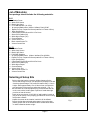
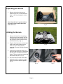
1
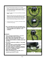
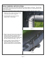
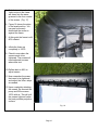
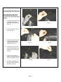
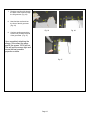
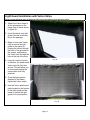
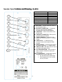
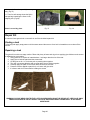
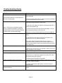
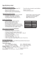
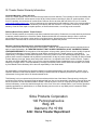
Sima XL Theater
Inflatable Indoor/Outdoor
Projection Screen & Amplified Speakers
User Manual for Models XL-8 and XL-12
www.simaproducts.com
Page 1
© 2006 Sima Products Corporation
140 Pennsylvania Ave.
Bldg #5
Oakmont, PA 15139
800-345-7462
www.simaproducts.com
PN 21744
Page 2
Table of Contents
TABLE OF CONTENTS ......................................................................................................................................................... 3
INTRODUCTION..................................................................................................................................................................... 4
LIST OF MATERIALS ............................................................................................................................................................ 5
SELECTING A SETUP SITE................................................................................................................................................. 5
UNPACKING THE SCREEN .................................................................................................................................................. 6
INFLATING THE SCREEN..................................................................................................................................................... 6
SCREEN INSTALLATION WITH VELCRO STRIPS ............................................................................................................. 9
LACING UP THE SCREEN .................................................................................................................................................. 11
LIGHT GUARD INSTALLATION WITH VELCRO STRIPS ................................................................................................. 13
SETTING UP THE INFLATABLE HOME THEATER FOR FRONT AND REAR PROJECTION ........................................ 14
SECURING THE SCREEN TO THE GROUND ................................................................................................................... 15
HOOKING UP THE SPEAKERS TO THE VOLUME CONTROL BOX ............................................................................... 16
SPEAKER SPECIFICATION AND DRAWINGS
- XL-SP-8 ............................... ..........................................................17
SCREEN DEFLATION & REPACKING ...............................................................................................................................18
REPAIR KIT.......................................................................................................................................................................... 19
TROUBLESHOOTING GUIDE ............................................................................................................................................. 20
SPECIFICATIONS SHEET................................................................................................................................................... 21
CONSUMER WARRANTY AND DEFECTIVE RETURN POLICY: ..................................................................................... 22
Page 3
Introduction
Congratulations on purchasing the XL Theater by Sima Products. Please read this instruction manual carefully before
installing your inflatable screen. When used properly according to this manual it will provide hours of entertainment for you
and your family.
General Information and Warnings
•
•
•
•
•
•
•
•
Do not over inflate. Use only the supplied air pump as directed. Never use an air compressor.
This screen is not a flotation device, do not use in any type of pool.
To avoid danger of suffocation, keep children away from the screen when inflating and deflating. Do not let children
sit or play on the screen. Always deflate and store screen immediately after use.
Do not use screen during high winds in excess of 15 mph or threat of lightning.
Do not smoke near the screen. Keep away from fire.
Do not use sharp objects in any manner around the XL Theater System.
Do not climb or sit on inflated surfaces.
Clean only with mild soap and water. Do not use harsh chemicals.
Sima Products has researched all regulations regarding the use of this XL Theater System. We have not found any
regulations related to the use of our screen; however we will not be responsible if some other regulations apply to this
product in the country you intend to operate the system. It is the users responsibility to be aware of such regulations and
obey them. Sima Products will not accept any responsibility for failure to meet local regulations.
Model
Size folded
Size Inflated
Weight (approximate)
XL-8
38”x20”20”
108”x96”x60”
50lbs
XL-12
40”x26”x26”
150”x120”x60”
70lbs
Page 4
List of Materials:
Your package should include the following materials:
XL-8
8’
8’
8’
2
1
1
1
1
1
4
4
52
1
1
Inflatable Frame
White PVC Screen
Black Light Guard
8” 80 Watt Speaker (XL-SP-8)
Air pump w/attachments (inflator / deflator) Part # 52387
Repair Kit (Four 6”square reinforced patches & 4 Tubes of Glue)
Nylon Storage Bag
Clear Plastic Ground Sheet 63"x115"x0.1mm
Stereo RCA Cables (30’)
White Nylon Ropes (20')
Ground Stakes
Velcro Quick Ties
Black Laced Screen Tie
Volume Control Box
XL-12
12’
12’
12’
2
1
1
1
1
1
4
4
70
1
1
Inflatable Frame
White Vinyl Screen
Black Light Guard
8” 80 Watt Speakers
Air pump w/attachments (inflator / deflator) Part # 52388
Repair Kit (Four 6”square reinforced patches & 4 Tubes of Glue)
Nylon Storage Bag
Clear Plastic Ground Sheet 63"x160"x0.1mm
Stereo RCA Cables (30’)
White Nylon Ropes
Ground Stakes
Velcro Quick Ties
Black Laced Screen Tie
Volume Control Box
Selecting A Setup Site
Select a site that has the necessary height clearance for the
screen and enough room for your projector to properly focus and
size the projected image. The screen will stand nearly 11 feet in
height. Allow approximately 15 to 20 feet in front (or behind for
rear-projection) of the screen to adjust the projector. (Fig. 1)
Be sure there are no sharp objects lying on the surface such as
rocks, roots, sticks, broken glass or pieces of metal that might
puncture or tear the screen.
Check to be sure that an 110V/120V AC wall outlet is in reach to
plug in the air pump. Use a properly grounded GFI outlet if using
the product outdoors.
Unpack the screen at the location in which it will be inflated.
Once a site has been selected and prepared, lay out the clear
plastic ground cloth in the location that the screen bases will sit
on when inflated as shown at right.
Page 5
Fig.1
Unpacking the Screen
1. Remove all the items from box as
shown at right. Don’t cut the boxes too
deep, as this may damage the screen.
(Fig. 2)
Note: Keep this box in good condition,
as it may be used to store the screen
when not in use.
Fig. 2
Inflating the Screen
1. Remove the frame from the package.
Unroll the screen as shown at right. Be
sure both bases are facing the correct
way. (Both air valves should be facing
the same direction.) (Fig. 3)
2. Plug the AC air pump into an AC power
outlet. Note: Power supply must be
120V AC, 60 Hz. Use a properly
grounded GFI outlet if using the product
outdoors.
Fig. 3
3. Locate the air inlet/outlet valves. You
will notice that each valve on each base
has two layers of seals that cutoff the
airflow. The outer seal is a threaded cap
that screws into place. (Fig. 4)
4. The inner seal is a rubber check valve
designed to hold in air when a certain
amount of pressure presses against it.
(Fig. 5)
Fig. 4
Page 6
Fig. 5
5. (Fig. 6) shows both style pumps for the XL Theater
System. The top picture shows the pump included with the
8’ foot model and below it shows the pump for the 12’
model. Both style pumps are marked with an “inflation” port
for blowing up the frames.
6. Attach the inflator hose to the pump inflation port marked
“Inflate”. (Fig. 7)
7. Attach the other end of the AC pump hose to one of the air
valves on the frame by pushing the end firmly into the
inflation port. None of the attachments should be used on
the end of the hose. Be sure to close the unused valve so
it doesn’t leak air while inflating the screen. (Fig. 8)
8. Turn the pump to the “on” position. (On Switch is located
on the face of the pump).
NOTE: THE FRAME SHOULD NOT TAKE MORE THAN 5
MINUTES TO INFLATE. MAKE SURE THE PUMP ISN’T
IN USE FOR MORE THEN 15 MINUTES. IT CAN
OVERHEAT!
WARNINGS:
• Never attempt to disassemble or close the
openings while pump is operating.
• Never leave pump unattended while in use.
• Never allow sand, small rocks etc… to be
sucked into the inflation or deflation port while
operating.
• Do not use under wet conditions – keep away
from water
• Never look into or point the inflate port toward
your eyes while pump is operating.
• The power supply cord cannot be replaced. If
the cord is damaged, contact Sima customer
service for a replacement pump.
• Keep away from children
• When used outdoors or near water, use a
properly grounded GFI outlet.
Page 7
Fig. 6
Fig. 7
Fig. 8
5. As the frame fills with air, be sure it is clear of any nearby
objects. Guide the frame up as it fills with air, helping
to unfold and expand it. It should take approximately 5
minutes for the screen to inflate. (Fig. 9 - 12)
Fig. 9
6. When the screen is about 80% full (frame is standing up
but there is a slight dip in the top part of the frame),
remove the hose from the inlet/outlet valve while the pump
is still in the “on” position. (Fig. 13) (If in the “off” position
you will lose air through the pump) After attaching the
screen to the frame in the following steps, you will “top it
off” by re-connecting the pump and fully inflating the
frame.
Fig. 10
You are now ready to attach the screen using either the
screen lace or Velcro strips. Please see instructions for
attaching the screen to the frame further on in the
instruction manual.
Tip: If connecting the screen to the frame is difficult,
release some air to allow for more slack in the frame.
Fig. 11
7. After the screen has been attached to the frame, continue
to inflate the frame so that the screen is pulled taut. (Fig.
14) Check the valve on the other base. Remove the cap
and check to make sure the inner seal is seated correctly.
In final be sure both valves are sealed correctly.
Fig. 12
Note:
•
•
•
The dark colored material from which the Inflatable
Theater Frame is construction tends absorb the heat
from the sun, which causes the air inside the frame to
warm up and expand if the screen is used on a sunny
day. If the frame is left out overnight, the air inside
the frame will cool and contract, which may cause the
frame to sag slightly. The sagging is not due to the
frame losing air, and can be corrected by "topping
off" the frame with air prior to use.
It is recommended to keep the supplied air pump on
hand to add additional air when using the XL Theater
System during an all day event.
Be sure to deflate frame and store after usage.
Fig. 13
Fig. 14
Page 8
Screen Installation with Velcro Strips
You can attach the screen to the frame using either the Velcro strips or cloth lace. The cloth lace
typically gives a more professional look while the Velcro strips allow you to attach and remove the
screen more quickly.
Please use the following steps to attach the screen successfully using the Velcro strips.
1. Attach the Velcro strips to all the grommets
on the frame as shown in figure15.
2. Unroll the white vinyl screen from the
supplied tube in the package.
Fig. 15
3. Begin to lace each Velcro strip to secure the
screen to the frame by looping the Velcro
through the back of the grommet in the
screen, and passing the Velcro strip through
the hole in the top of the strip. (Fig. 16)
4. Leave a couple of inches of slack as you
attach each Velcro strip the first time
around. This will allow you to more easily
adjust the screen later once fully attached.
Fig. 16
Page 9
5. Each horizontal and vertical
Velcro strips in the frame
will share into the same
grommet in the four corners
of the screen. (Fig. 17)
6. Figure 18 shows the strips
in the laced position. You
can see how evenly
distributed the screen is
against the frame.
7. At this point the frame is still
80% inflated.
8. Inflate the frame up
completely to 100%.
9. Check to see where the
screen needs to be
tightened. The screen will
need adjusted to areas
where less taut.
Fig. 17
10. Deflate back to 80% to
adjust screen.
11. Now remember the areas
that need to be tightened
and adjust the Velcro strips
as needed.
12. Upon completely attaching
the screen, Re-connect the
pump and fill the screen
100% with air. This will pull
the screen tight and insure
the best possible projection
surface.
Fig. 18
Page 10
Lacing Up the Screen
As an alternative to the Velcro
Strip attachment method, the
screen can be attached with Nylon
Lacing.
1. Insert the lacing cord through
the back of the top left
grommet (A1) on the frame.
(Fig. 19)
Fig. 20
Fig. 19
2. Tie the cord using a secure
knot. (Fig. 20)
3. Feed the cord from the back
of the frame through the
upper left grommet on the
screen (S1) (Fig. 21)
Fig. 21
Fig. 22
4. Insert the end of the cord
from S1 into the front of the
grommet on the frame (A1)
(Fig. 22)
5. Pull the cord through A1.
Make sure the cord stays flat
and is not twisted. (Fig. 23)
Fig. 23
6. Feed the cord through the
back of the A2 grommet on
the frame. (Fig. 24)
Page 11
Fig. 24
7. Feed the cord from A2 through
the back of the screen through
the S2 grommet. (Fig. 25)
8. Now feed the cord back into
the front of the A2 grommet .
(Fig. 26)
Fig. 25
Fig. 26
9. Continue working around the
screen until you have laced all
of the grommets. (Fig. 27)
Upon completely attaching the
screen, Re-connect the pump
and fill the screen 100% with air.
This will pull the screen tight and
insure the best possible
projection surface.
Fig. 27
Page 12
Light Guard Installation with Velcro Strips
Please use the following steps to attach the light guard successfully using the Velcro strips.
1. Attach the Velcro strips to
all the grommets on the
frame rear of the as shown
in figure 28.
2. Unroll the black vinyl light
guard from the accessory
box in the package.
3. Begin to lace each Velcro
strip to secure the light
guard to the frame by
looping the Velcro through
the back of the grommet in
the screen, and passing
the Velcro strip through the
hole in the top of the strip.
Fig. 28
4. Leave a couple of inches
of slack as you attach each
Velcro strip the first time
around. This will allow you
to more easily adjust the
screen later once fully
attached.
5. Once the light guard is
attached to the frame,
tighten the Velcro strips.
6. Use the Velcro attachment
pads located on the bottom
of the light guard and the
frame to secure the light
guard for front-projection.
Fig. 29
Page 13
Setting up the Inflatable Home Theater for Front and Rear Projection
Projector Distance
Projector Angle
•
Typically, set up the projector a distance (1x – 1.5x) the
diagonal from the screen.
•
Attempt to position the projector so that it is
parallel to the inflatable screen.
•
In general, for a 16:9 screen ratio use 1.15x the diagonal for
projector distance. For 4:3 screen use 1.25x.
•
•
Follow the projector manufacturer’s instructions.
Care should be
taken so that the
projector is aligned
both horizontally
and vertically to the
front of the inflatable
screen.
•
If your projector has
a keystone
adjustment feature,
this may be used to
correct for the angle
being slightly off.
Rear Projection Setup
•
To use the inflatable screen with the projector placed
behind the screen, first lift the black light guard up so
that it does not block the white screen material.
•
For nighttime video viewing, the black light guard can
be removed from the frame.
•
There are two grommets located in the lower corners
of the light guard. To use the light guard to block
overhead light while using a rear-projector, use the
grommets to tie the light guard horizontally, so that it
blocks unwanted light, but allows the image from the
projector to be shown on the screen.
•
Adjust your projector to rear-projection mode following
the manufacturer’s instructions.
•
Use the white nylon ropes and ground stakes to keep the
light guard in position for rear projection.
Page 14
Light Guard
Grommets
Securing the Screen to the Ground
Use the ground stakes & tie down ropes to secure the screen. Attach the tie down ropes to the screen using the 4
attachment points located on the upper portion of the frame. If the ground stakes are unable to be used, apply the
rope ties to a secured object such as a sand bag to hold down the screen as shown below. Be sure to use an object
of sufficient weight (approx. 25 lbs) to secure the screen. Make sure the weighed object does not have sharp edges
that could tear or puncture the screen.
WARNING: KEEP AWAY FROM WATER. DO NOT PLACE OR STORE THIS WHERE THIS UNIT CAN FALL OR
BE PULLED INTO WATER. ALWAYS USE GFI OUTLETS FOR THE AIR PUMP AND SPEAKERS IF USED
OUTDOORS. KEEP ALL ELECTRICAL PARTS AND EXTENSIONS CORDS DRY. ALWAYS UNPLUG FIRST
FROM THE ELECTRICAL OUTLET.
• Warning: This screen can withstand winds up to 15mph. higher wind speeds will cause disruption in
viewing or the grommets to tear off. Deflate screen in excessively windy or severe storm conditions.
• Warning: Always survey the ground before staking the equipment. Electrical hazards may exist
underground. Overhead power lines may exist; always look-up and survey the electrical hazards above.
Page 15
Hooking up the Speakers to the Volume Control Box
It is suggested that you place the two speakers on the ground cloth next to the base of the frame.
The Volume Control Box should sit next to the DVD player. It lets you adjust the audio volume level
without having to walk up to each speaker.
To connect the speakers for use with your projector and DVD player use the RCA cables provided. Follow the steps and
diagram below.
1. Connect the L + R audio output of your DVD player to the L + R input on the Volume Control Box.
2. Connect the Video output of your DVD player to the Video input of your projector.
3. Connect the L Audio output of the Volume Control Box to the L Line input of the XL-SP speaker you have located
to the left of the screen and frame.
4. Connect the R output of the Volume Control Box to the R Line input of the other XL-SP speaker you have located
to the left of the screen and frame.
5. Plug the AC line cords into the AC Power Inlet on the back of each speaker and insert the other ends into a
properly grounded GFI outlet.
6. Set the volume level on the Volume control box to min.
7. Set the Line Input level, Bass and Treble controls on the back of each speaker to the middle (12:00 o’clock) position.
8. Turn on the Power switch on the back of each speaker. The light in the switch will light indicating AC power is on.
9. Place a DVD or CD into the DVD player and start the movie or audio.
10. Adjust the Volume Control Box for a good audio level. If you hear no sound, be sure the DVD is playing. Check
all cable connections. If the sound is not loud enough with the Volume Control Box set to maximum, turn the Line
Input Level control on the back of each speaker up. Also, be sure any volume setting in the DVD player or
projector is set properly.
XL-SP8 Speaker
Page 16
Speaker Specifications
cations and Drawing - XL-SP-8
Model
Woofer Size
Wattage
Frequency Response
Dimensions (in.)
Weight (lbs)
Microphone Input
Stereo Input
Ground Stands Included
1
2
XL-SP-8
8”
80w
55Hz-18kHz
18.1x12.2x10.6
19.8 lbs.
YES (1/4”)
YES
NO
3
1. MIC LEVEL – Used to adjust the volume of
the microphone input.
2. MIC INPUT CONNECTOR – ¼” balanced
Input for connecting low impedance
microphones to the Low-Noise preamp.
3. LINE LEVEL – Used to control the level of
the line input.
4. LINE INPUT CONNECTOR - RCA Input for
connecting line level signals.
5. TREBLE CONTROL - Controls the high
band of the Channel Equalizer, +/- 10 dB at
3.5kHz.
6. LINE OUTPUT – ¼” balanced output
connector used to link multiple XL-SP8s
together.
7. BASS CONTROL - Controls the low band of
the Channel Equalizer, +/- 12 dB at 100Hz.
8. AMP CLIP LED - LED lights when the amp is
at maximum and about to clip.
9. VOLTAGE SELECTOR – Set this switch to
either 115VAC or 220VAC to match your
power source.
10. AC POWER INLET – Connect the supplied
standard IEC AC power cable here.
• On / Off Switch with indicator light
• Extra Replacement Fuse included,
use only T2A fuse
4
5
6
7
8
9
10
Page 17
Screen Deflation & Repacking
It is recommended to remove the screen from the frame before packing to prevent damage and creases in the screen.
1. To deflate the frame, uncap one of the air
valves from either base. (Fig.30)
2. Press in on the inner check valve. After 20
seconds the seal should lock into place. This
will allow you to squeeze most of the air out
prior to hooking up the pump. (Fig.31)
Fig. 30
Fig. 31
3. Squeeze the air out of the frame until it’s
deflated to ground level. (Fig.32)
4. Connect the hose to the deflation inlet on
the pump. Connect the other side of the hose
to the air valve on either base. (Fig.33 shows
both the 8’ & 12’ model pump and where the
hose connects to the deflation inlet.)
5. Turn the pump to the “on” position for the
next few steps.
6. Layout the frame as shown in figure 34.
Fig. 32
7. Fold each base in half. Now begin to roll
the frame from one base down to the next
base. (Fig.35)
8. Turn the pump “off” after the screen is
rolled up for storage. (Fig.36)
9. Unplug & remove the pump from the
frame. Pack the pump up and away for
storage.
Fig. 33
Fig. 34
Note: The pump can be used intermittently
as you deflate and pack up the frame. Feel
free to use it when necessary to deflate any
air as needed throughout the entire
deflation/repacking process.
Fig. 35
Page 19
Fig. 36
10. Insert the frame into your Nylon storage
bag. (Fig.37)
11. Then for safe storage insert the Nylon
storage bag containing the frame in the
shipping box. (Fig.38)
Store in a cool dry place.
Fig. 37
Fig. 38
Repair Kit
In case the frame gets a hole or tear while in use Sima included a patch kit.
Finding a leak
To find any leak apply soapy water to all the seams around the screen. Once hole is located be sure to clean off the
surface.
Repairing a leak
The glue will not stick to a soapy surface. Rinse with plenty of water and dry prior to applying glue. Make sure the screen
is deflated prior to procedure.
1. Using patch kit cut a piece of material about 1 inch larger than the size of the tear.
2. Apply glue to both the patch and the screen itself.
3. Let the glue set for 1 to 3 minutes prior to pressing them together.
4. The glue is a contact adhesive and must get tacky prior to sticking together.
5. Carefully apply the patch to the screen and hold for a few minutes
6. Pressure must be applied to patch for 2 to 3 hours until glue dries.
7. It is best to wait 4 to 8 hours before inflating the screen
WARNING: PLEASE WEAR PROTECTIVE LATEX GLOVES WHEN USING THE REPAIR KIT. KEEP GLUE AWAY
FROM EYES & MOUTH. DO NOT INHALE THE GLUE AND WASH HANDS THOROUGHLY AFTER USING
SUBSTANCE.
Page 20
Troubleshooting Guide
Problem
Solution
Wrinkles & Creases in the screen
1. Remove the screen prior to deflating and roll it back onto the
tube for storage.
Note: Some wrinkles are normal and will not
affect the viewing image.
The frame is deflating over time
2. Setup the screen and frame in a warm environment (Sunlight)
to remove the wrinkles from the screen.
1. Be sure to remove the air pump hose after inflating. Air can
leak back through the pump if not removed.
2. Check the inner rubber air valves are seated properly prior to
closing outer threaded cap.
Note: If the frame is left inflated overnight
during a moderate temperature change the
frame will show a loss of air pressure. Be sure
to deflate frame and store after usage.
3. Listen for air holes in the frame around the seams. You may
use mild soap and water to locate the leak.
No power to the speakers
4.Be sure to remove all soap residues prior to using a patch kit.
1. Check that the AC power cables are plugged into a working
outlet.
2. Check the AC power cable connection on the back of the
speakers. Be sure it is inserted completely.
No audio sound from the speakers
3.The off/on switch should illuminate when on if power is
connected correctly. If power is still not present check to see if
the fuse needs replaced. When removing the fuse block you will
find a spare fuse.
1. Check that all the audio cables are connected correctly.
Distorted Sound from speakers.
2. Be sure the volume levels on the speaker, volume control box
and DVD player are set correctly
1. If you are playing at a loud volume level, reduce the volume
Audio humming noise in the speaker
1. Keep audio cables away from the AC wires.
2. Keep all your components plugged into the same GFI outlet.
This will eliminate ground looping.
Video is not bright enough on the screen
Part of the picture is missing viewing in the rear
projection position.
3. Reduce the level control on the speaker.
1. Use a projector with enough lumens to better view your video
for certain outdoor conditions.
2. Use the supplied black light guard to cut down on rays of
unwanted light.
1. Place the projector on a stand so its height is centered in the
screen.
Page 21
Specifications sheet
Inflatable Frame Descriptions
- Commercial grade mesh reinforced PVC
- Ultra-sonic welded seams
- Inflates in under 5 minutes with pump
- Clear PVC plastic ground sheet included
- Dual self-sealing air valves for quick deflation
- Repair kit included
- Rust-free plastic grommets
Standard Screen Descriptions
−
16’x9’ HD Widescreen, 4x3 format compatible
- Compatible with all types of projectors
- Hi-Definition, bright white vinyl material
- Vinyl blackout screen Included (8’ or 12’)
Speaker Specifications
- Commercial grade amplified speakers
- Moisture resistant speaker cones
- Bass and treble control on speaker
- Universal speaker stand mount (stand not included)
- Line-out allows for expansion of sound system
- 2-Channel passive volume control box included
- 30 foot Stereo RCA audio cables included
-
Optional black screen lacing included
Front and rear projection capable
Adjustable hook & loop strips
Black Trimmed screen
Model
Woofer Size
Wattage
Frequency Response
Dimensions (in.)
Weight (lbs)
Microphone Input
Stereo Input
Ground Stands Included
Other Accessories Included (All Models)
- (4) 6” Ground Stakes
- (4) Stabilization Rope (20’) Tie-Downs
- (1) Repair Kit (4 patches and 4 tubes of glue)
- (1) Air Inflator/Deflator (UL Listed) with Hose – 120v AC
- (1) Plastic Ground Sheet
- (1) Screen and Frame Storage Duffel
- (1) Volume Control Box
- (1) Set of L-R RCA Audio Cables: 30ft
- (1) Set of adjustable screen strips (52 for XL-8, 70 for XL-12)
Technical Specifications
Frame Material - .6mm PVC with 1000D Substrate Mesh Reinforcement
Screen Material – .15mm PVC
Product Dimensions
XL-8 – 108”x96”x60” (Inflated)
XL-8 – 38”x20”x20” (folded)
XL-12 –150”x120”x60” (inflated)
XL-12 – 40”x26”x26” (folded)
Shipping Weights XL-8 – approx. 50lbs
XL-12 – approx. 70lbs
Air pump - 120v AC UL Listed Inflator/Deflator
Model 52387 (XL-8)
Model 52388 (XL-12)
Warning tags on box and screen – Prop. 65 Compliant
Page 22
XL-SP-8
8”
80w
55Hz-18kHz
18.1x12.2x10.6
19.8 lbs.
YES (1/4”)
YES
NO
Consumer Warranty and Defective Return Policy:
Sima’s Outdoor Inflatable Home Theater Kits
XL Theater Inflatable Screen - 6 month (180 day) Limited Warranty Sima Products Corporation
Limited Warranty
Sima Products Corp. (“Sima”) warrants that if the accompanying product proves to be defective to the original purchaser in material
or workmanship within 180 days from the original retail purchase, Sima will, at Sima’s option, either repair or replace same without
charge (but no cash refund will be made).
IMPORTANT: TO QUALIFY FOR WARRANTY COVERAGE YOU MUST REGISTER YOUR XL
THEATER WITH SIMA PRODUCTS WITHIN 10 DAYS OF PURCHASE. ALL WARRANTY
CLAIMS WILL REQUIRE WRITTEN PROOF OF TIMELY WARRANTY REGISTRATION. YOU
CAN REGISTER FOR WARRANTY COVERAGE IN THE FOLLOWING WAYS:
1. Mail the warranty card from the product, post marked within 10 days of purchase to: Sima Products, 140
Pennsylvania Ave., Building #5, Oakmont, PA 15139
2. Register your warranty on line at www.simaproducts.com
3. Register your warranty by telephone with Sima Customer service by calling 800-345-7462 x1270
What you must do to enforce Warranty:
You must deliver, mail or ship the product, together with both the original bill of sale and this limited Warranty statement as proof of
warranty coverage to:
Sima Products Corp.
Attn: Customer Service
140 Pennsylvania Ave.
Bld. #5
Oakmont, PA 15139
Phone # 412-828-3700
Fax # 412-828-3775
It is recommended that you call Sima at the number listed above to obtain a return authorization number.
Limitation of Liability and Remedies
This warranty does not cover damage resulting from accident, misuse or abuse, neglect, improper service and/or
maintenance or if the screen has been inflated with a pump other than the original one supplied by manufacturer.
Use of unauthorized service, replacement parts or attachments will void this warranty. Misuse includes any use
of this product for other than its intended uses as described in the product manual.
Sima shall have no liability for any damages due to lost profits, loss of use or anticipated benefits, or other incidental, consequential,
special or punitive damages arising from the use of, or the inability to use, this product, whether arising out of contract, negligence,
tort or under any warranty, even if Sima has been advised of the possibility of such damages. Sima’s liability for damages in no event
shall exceed the amount paid for this product. Sima neither assumes nor authorizes anyone to assume for it any other liabilities. Some
states do not allow the exclusion or limitation of incidental or consequential damages, so the above limitation or exclusion may not
apply to you. This warranty gives you specific legal rights, and you may also have other rights which vary from state to state.
Page 23
Speaker System - 90 Day Limited Warranty Sima Products Corporation
Limited Warranty
Sima Products Corp. (“Sima”) warrants that if the accompanying product proves to be defective to the original purchaser in material
or workmanship within 90 days from the original retail purchase, Sima will, at Sima’s option, either repair or replace same without
charge (but no cash refund will be made).
What you must do to enforce Warranty:
You must deliver, mail or ship the product, together with both the original bill of sale and this limited Warranty statement as proof of
warranty coverage to:
Sima Products Corp.
Attn: Customer Service
140 Pennsylvania Ave.
Bld. #5
Oakmont, PA 15139
Phone # 412-828-3700
Fax # 412-828-3775
It is recommended that you call Sima at the number listed above to obtain a return authorization number.
Limitation of Liability and Remedies
Sima shall have no liability for any damages due to lost profits, loss of use or anticipated benefits, or other incidental, consequential,
special or punitive damages arising from the use of, or the inability to use, this product, whether arising out of contract, negligence,
tort or under any warranty, even if Sima has been advised of the possibility of such damages. Sima’s liability for damages in no event
shall exceed the amount paid for this product. Sima neither assumes nor authorizes anyone to assume for it any other liabilities.
Some states do not allow the exclusion or limitation of incidental or consequential damages, so the above limitation or exclusion may
not apply to you. This warranty gives you specific legal rights, and you may also have other rights which vary from
state to state.
Page 24
XL Theater Dealer Warranty Information
Consumer Warranty – How it will work:
Sima’s XL Theater System carries a 6 month/180 day limited consumer warranty. This warranty covers workmanship and
quality defects for Sima XL series screens, and a 90 day limited consumer warranty for Sima XL series speakers. In the
event of a problem, the consumer will contact Sima Customer Service at either 800-345-7462 x1270,or via e-mail at
[email protected], and our customer service representatives will handle the claim in the most expeditious
manner. All warranty claims will be handled by Sima directly with the consumer. For products covered by a valid Sima
warranty, Sima will either repair or replace product, at Sima’s sole discretion, at no charge to the consumer.
Defective Return Policy with XL Theater Dealers:
Sima XL Theater products do not qualify under Sima’s standard return policy. Dealers are not to take back any defectives
or warranty related claims from a customer. Rather, Dealers should refer the customers directly to Sima’s customer
service department in the phone number and/or e-mail listed above. We welcome all our dealers acting as liaisons
between their customers and our customer service department to expedite this process.
Warranty / Defective Replacement for Commercial Rental Applications:
The XL Theater product line lends itself well to event rentals. However, the standard Sima consumer warranty does not
apply to rental applications. XL THEATER PRODUCT THAT IS USED FOR RENTAL IS NOT COVERED BY SIMA’S
CONSUMER WARRANTY. Rental product will be assigned a unique product code by Sima in order to qualify for special
“Rental Product Warranty coverage” When the rental dealer receives Sima XL Theater product, it is the dealer’s
responsibility, to completely check/inflate all product to insure the product is free from workmanship/quality issues. This
product check must be completed and any defects reported within 10 days of product receipt. To qualify for Sima’s Rental
Product Warranty coverage, dealer name and product code must be registered with Sima Customer Service. Dealers
can either call Sima at 800-345-7462 or log on to the company website at www.simaproducts.com, to register for Rental
Warranty Coverage. NOTE: Consumer Warranty coverage is void after product rental, and all service/repair not covered
by Sima Rental Product Warranty will be the sole responsibility of the rental dealer.
No responsibility is assumed for any special, incidental or consequential damages. No other warranty, written, oral or
implied is assumed or authorized by SIMA. The liability of SIMA hereunder is expressly limited to a claim for a repair or
replacement for the goods sold or as otherwise stated herein.
This Warranty is to be construed and enforced in accordance with the law of the State of Pennsylvania, including the
provisions of the Uniform Commercial Code as adopted and from time to time amended in the State of Pennsylvania, and
not the Convention for the International Sale of Goods. Should any action of law or in equity be brought by any person
under this Warranty, such action shall be brought only in the Court of law in the United States. If you have any questions
regarding applications or specifications, or to obtain warranty service on this or any SIMA product, contact the SIMA
Customer Support Group.
Sima Products Corporation
140 Pennsylvania Ave
Bldg. #5
Oakmont, PA 15139
Attn: Home Theater Department
Page 25


![User Manual [PDF 80.57KB]](http://vs1.manualzilla.com/store/data/005808718_1-0fabb64b5e1899e1380b2d49f3e9d3a7-150x150.png)