1
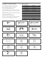
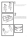
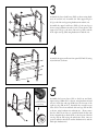
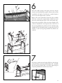
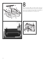
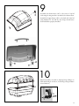
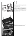
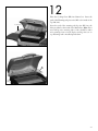
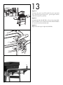
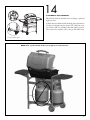
SERIAL#:
T360 Propane Barbecue
S A F E U S E , C A R E A N D A S S E M B LY M A N U A L
DANGER
If you smell Gas
1. Shut off gas to the appliance.
2. Extinguish any open flame.
3. Open lid.
4. If odor continues, keep away from the
appliance and immediately call your
gas supplier or your fire department.
WA R N I N G
1. Do not store or use gasoline or other
flammable vapours and liquids in the
vicinity of this or any other appliance.
2. An LP cylinder not connected for use
shall not be stored in the vicinity of this
or any other appliance.
WA R N I N G
Failure to follow all of the Manufacturer’s
instructions could result in hazardous
fires, explosions, property damage, or
serious personal injury or even death.
ONE
YEAR
LIMITED
WA R R A N T Y
85-1630-2
G30505
WA R N I N G
Follow all leak check procedures carefully
prior to operation of barbecue, even if
grill was dealer assembled. Do not try to
light this barbecue without reading the
Lighting Instructions section of this manual.
Read and save this manual for future reference.
If pre-assembled, leave this manual
with unit for consumer’s future reference.
For product inquires, parts, and warranty and
troubleshooting support, please call 1-877-707-5463.
THIS BARBECUE IS FOR
O U T D O O R U S E O N LY
WA R R A N T Y
1 Year Limited Warranty
This Masterchef® Barbecue carries a 1 year limited warranty against defects in
manufacturing workmanship. This Limited Warranty is nontransferable and
becomes void if used for commercial or rental purposes. This warranty applies
only when grill is used in Canada. The bill of sale or a copy will be required
together with the serial number and model number when making any warranty
claims from Trileaf Distribution.
Trileaf Distribution reserves the right to have its representatives inspect any product or part prior to honoring any warranty claim. Trileaf Distribution shall not be
liable for any transportation charges, shipping & handling charges or labor cost.
This warranty is for replacement of defective parts only. The Manufacturer will
not be responsible for incidental or consequential damages or any labor cost.
Inability to provide proof of purchase, or if warranty coverage has expired, any
request for parts will be subject to parts, shipping and handling fees.
This limited warranty does not cover damage due to chipping and scratching of
porcelain or painted surfaces including Cooking grates, nor does it cover corrosion or discoloration due to misuse, lack of maintenance, grease fires, hostile environments, accidents, alterations, abuse or neglect, improper installation and
failure to read and/or abide by any product warnings. This limited warranty does
not cover any damage sustained during removal or storage of this BBQ. Part failure due to lack of cleaning and maintenance, or use of improper cleaning products
such as Oven Cleaner will not be covered under this manufacturers warranty. This
limited warranty does not cover any scratches or dents, corrosion or discoloring
caused by heat, abrasive or chemical cleaners. Parts installed from other manufactures will nullify this warranty.
1 Year Limited Warranty
For one year from the date of original retail purchase Trileaf Distributions will
replace any grill part that fails or is found to be defective to the degree of nonperformance under normal household use, during the limited warranty period. Trileaf
Distributions ltd. are not responsible for any grill damage sustained during moving, storage, assembling or cleaning. Unless otherwise noted, as in above limitations, all components are covered for a period of one year.
Important: Should you have difficulty operating this product, or have a part
that has become defective within the stated warranty period, DO NOT
RETURN TO STORE. STORES DO NOT STOCK REPLACMENT PARTS
AND ARE UNABLE TO HELP WITH TROUBLESHOOTING ADVICE.
PLEASE CALL 1-877-707-5463. Have your Proof of purchase, serial number
and model number available so that the customer support agent can be
of assistance.
Purchaser: By accepting delivery of this Barbecue the purchaser, hereby accepts
the foregoing and expressly waives any other remedy and damages, direct, indirect,
and consequential.
INFORMATION
INSTALLATION
ADDITIONAL
WA R N I N G S
The installation of this appliance must be in accordance with all local codes, or in
the absence of local codes:
• Canadian installation must conform to the current national standards, which at
this time are CAN/CGA-B149.1/2-Natural Gas/Propane installation code.
a) Do not store a spare LP-gas cylinder under or near this appliance;
b) Never fill the cylinder beyond 80 percent full; and
c) If the information in “(a)” and “(b)” is not followed exactly,
a fire causing death or serious injury may occur.
Minimum clearance to adjacent combustible materials:
• 76 cm (30˝) from furthest protruding edge on side of barbecue.
• 76 cm (30˝) from furthest protruding edge on back of barbecue.
See Drawing A
Always keep the area around this barbecue clean and clear of any and all combustible materials such as gasoline or other inflammable liquids, paper or oily rags.
• Do not operate this barbecue under any overhanging or unprotected construction.
• Remember this barbecue is for outdoor use only and is not for use
on any boat or recreational vehicle.
• Use this barbecue outdoors in a well-ventilated area and we recommend
at least 3 m (10’) from any dwelling or other buildings.
• Do not use in garages, or any other enclosed area.
• Do not leave your barbecue unattended while in operation.
• Do not obstruct the flow of combustion and ventilation air to the barbecue.
• Do not use while under the influence of drugs or alcohol.
• Do not store any spare L.P. (propane) cylinder, full or empty,
under or near your barbecue.
• Do not allow children to play anywhere near the barbecue.
•
Minimum clearance of 76 cm (30”)
on both sides and back of the barbeque.
Drawing A
USE OF
L . P. G A S C Y L I N D E R
Self-contained
The self-contained (propane) gas system is designed to be used with only a 9.1 kg
(20 lb) propane cylinder equipped with a type-1 cylinder valve and incorporating an
overfill protection device (O.P.D.). This barbecue cannot be connected to an existing
#510 P.O.L. type valve cylinder (which has left-handed threads).
Propane Gas System
DO NOT connect to a propane cylinder exceeding 9.1 kg capacity or
use a cylinder with any other type of cylinder valve connection device.
The type-1 valve can easily be recognized by the large external thread on the outside
of the valve. Older existing valves do not have this outer external thread. Any attempt
to connect a regulator to any connector other than the mating type-1 connector could
result in fires, injuries or property damage, and could take out the important safety
features built into the type-1 system. Also connecting the #510 P.O.L. fitting to the
cylinder will negate the flow control and the temperature shut-off features built into
the new type-1 connection system.
• The cylinder should not exceed 472 mm (18 1/2˝) in height and
317 mm (12 1/2˝) in diameter.
LP-gas supply cylinder to be used must be constructed and marked in accordance
with the specifications for LP-gas cylinders of the U.S. Department of Transportation
(DOT) or the National Standard of Canada, CAN/CSA-B339, Cylinders Spheres
and Tubes for the Transportation of Dangerous Goods.
1
DANGER
•
NEVER store a spare LP tank under
or near grill or in enclosed areas.
Never fill the cylinder beyond
80% full.
• An overfilled or improperly stored
tank is a hazard due to possible gas
release from the safety relief valve.
• If you see, smell or hear escaping
gas, immediately get away from
the LP tank/grill and call your
fire department.
• If the above is not followed exactly,
a fire causing death or serious injury
may occur.
•
The Cylinder must also be equipped with:
• A shut-off valve with a correct cylinder valve outlet as specified in current standards.
• Canada: CAN/ CGA 1.6g-M97 Outdoor Gas Grills.
• U.S.A: ANSI Z21.58a-2006/CSA 1.6a-2006 Outdoor Cooking Appliances.
a) Constructed and marked in accordance with the Specifications for LP-Gas
Cylinders of the U.S. Department of Transportation (D.O.T.) or the National
Standard of Canada, CAN/CSA-B339, Cylinders, Spheres and Tubes for
Transportation of Dangerous Goods; and Commission, as applicable; and
b) Cylinder connection device compatible with
the connection for outdoor cooking appliances.
c) A listed Overfilling Protection Device (O.P.D.).
d) A safety relief valve with direct connection to the vapour space of the cylinder.
e) A collar to protect the tank shut-off valve.
f ) A device for vapour withdrawal.
g) A ring on the bottom to secure the tank to its support assembly.
Warning
Always turn off the cylinder valve completely when the barbecue is not in use.
Always handle the tank valve with utmost care.
• Never connect an unregulated L.P. gas cylinder to the barbecue.
• Always keep the cylinder, in use, securely fastened in an upright position.
• Never store a spare cylinder, empty or full, near or under the barbecue
when in operation.
• Never expose the cylinders to direct sunlight or excessive heat.
• Never insert any kind of objects into the valve outlet as this may damage the
backcheck; a backcheck that is damaged can leak, and a leaking propane cylinder
can result in fires or explosions, property damage, severe injuries or death.
•
•
To Connect Regulator
Carefully insert brass nipple of regulator connection into tank outlet. Screw black
plastic nut clockwise onto tank valve outlet until it comes to a stop. Hand-tighten
only. Do not use tools of any kind.
TRANSPORTATION
AND STORAGE
O F L . P. C Y L I N D E R
The propane cylinder is totally safe when handled properly, but if misused, the
result could be an explosion or fire resulting in serious personal injury and/or
property damage.
Warnings
Always recap the cylinder with cap provided when not connected to the barbecue.
• Do not store the cylinder in any enclosed area such as a garage, and make sure
the storage area has lots of ventilation.
• Do not store the cylinder near any appliances, or in any areas that may become
hot such as the trunk of a vehicle.
• Make sure the cylinder is out of the reach of children.
• When transporting or storing the cylinder, make sure it is in an upright
position and not on its side.
• Do not smoke around the cylinder, especially when transporting it in a vehicle.
•
2
FILLING THE
L . P. C Y L I N D E R
For safety reasons the LP gas cylinder, if supplied with your barbecue, has been
shipped empty. The cylinder must be filled prior to use and must have the air
purged. For safety, follow these instructions when having your cylinder filled:
• Have only your local qualified LP gas dealer fill or repair a cylinder.
• Do not overfill the cylinder beyond the safe 80% fill level.
• Make sure the dealer tests and checks the cylinder for leaks after filling.
WA R N I N G
If the above instructions are not completely adhered to,
it could cause a fire /explosion, resulting in death or serious Injury,
or property damage.
SAFETY HOSE
AND REGULATOR
Propane Models: Your barbecue is designed to operate on L.P. propane gas at
a pressure of 2.74 Kpa (11˝ water column). A regulator preset to this pressure is
supplied with the barbecue and must be used.
This regulator is equipped with the type-1 quick-closing connecting system,
which incorporates these safety features:
• Will not allow gas to flow until a positive seal has been made.
• Has a thermal component that will automatically shut off
the flow of gas between 115–150ºC (240–300ºF).
• Has a flow limiting feature, which will restrict the flow of gas
to 10 cubic feet/hour.
Warning
Should the large, black thermal-sensitive coupling nut be exposed to any extreme
temperatures above 115ºC it will soften and allow the regulator probe to disengage from the valve, and will shut off the gas. Should this occur, do not try to
reconnect the nut; instead replace the whole regulator assembly with a new one
(see the attached parts listing for details). The regulator probe also contains a flowsensitive feature, which limits the flow of gas to 10 cubic feet/hour, in the event of
a regulator malfunction or hose leak. If the flow control feature is activated, the
cause of this excessive gas flow should be investigated and corrected before using
the barbecue again.
3
Attention: Improperly lighting the barbecue can activate the flow control feature,
resulting in lower heat output. If this occurs, the re-flow feature must be reset by
turning off all the burner controls and the cylinder valve. Wait at least 30 seconds
before slowly turning on the cylinder valve, and then after another 5 seconds turn
the burner valve on and light the barbecue.
Never connect this barbecue to an unregulated propane gas supply, or to
another kind of gas. Do not alter or change the hose or regulator in any way.
• Visually inspect the whole hose assembly before each use for evidence of wear or
damage such as cracks, burns, or even cuts. If any damage is found, replace the
assembly before using the barbecue. Use only the recommended replacement hose.
• To avoid possible damage to the hose, do not allow any grease or other hot
materials to fall on the hose, and make sure the hose does not contact any hot
surfaces of the barbecue.
• The connection fitting must be protected when it’s disconnected from the
cylinder. Do not allow the fitting to bump or drag on the ground as nicks and
scratches could help create a leak when connecting back to the cylinder.
• It is important to do the “Leak Test” procedure every time a cylinder is refilled,
or any of the components are changed, and especially at the beginning of a
new season.
•
SAFETY
LEAK TESTING
Attention: A leak test ensures that there are no gas leaks prior to lighting
your barbeque.
Perform A “Leak Test”
Before lighting your barbecue for the first time.
Every time the cylinder is refilled, or any component is replaced.
• At least once every year, preferably at the start of the season.
• When having difficulty lighting burners, or experiencing irregular burn patterns.
•
•
The “Leak Test” must be done outdoors, away from heat, open flames and flammable liquids. Do not smoke while performing the test. Use only a mixture of
50/50 liquid soap and water for leak testing. Never use a match or open flame.
The Following Must Be Checked
The tank valve including the threads into the tank (drawing C).
All tank welds (drawing B).
• Regulator fittings and tank connections (drawing C).
• All hose connections (drawing D),
plus side burner hoses if so equipped (drawing E).
• With a newly filled and tested propane tank attached to the barbecue and all
the controls turned OFF, slowly open the cylinder valve one full turn.
• Brush Soap solution on all connections and components
listed above and shown in the drawings B, C, D and E.
• Look carefully for bubbles forming, which is an indication of leaking gas.
• Tighten the connections at the bubbled areas until re-testing shows no
indication of any leaks (shut off cylinder while correcting any leaks).
• Shut off the cylinder valve and ensure all control valves are off.
• Do not use the barbecue if any leaks cannot be stopped. Turn off the
gas cylinder valve, remove the gas cylinder and seek assistance from
a qualified gas appliance service mechanic or gas dealer.
•
•
Drawing B
Drawing D
Drawing C
Drawing E
(if equipped with a side burner)
4
PRIOR TO USING
Do not use your barbecue until you have carefully read and fully understand
all the information in this manual. Please ensure the following:
• Your barbecue is properly assembled.
• There are no leaks in the system (see “Leak Test”).
• The burner is properly assembled, with the venturi tubes seated over the
valve outlets (drawing F) and that there is nothing blocking the venturi
tubes (drawing G).
• Ensure that all power cords and/ or gas supply hoses will not touch or be
near the surfaces that will get hot.
• The barbecue is in a safe location (see installation).
Insert valve outlets into Venturi tubes
approximately 6mm (1/4”)
Drawing F
WA R N I N G
During shipment or storage, it’s possible that small insects like spiders could
find their way into the venturi tubes and nest or make webs. This could block
the flow of gas through the venturi tube causing a smoky yellowish flame, or
prevent a burner from lighting. It could even cause the gas to burn outside the
Venturi tube, which could seriously damage your grill. If these occurs, turn off
the gas flow and wait for the barbecue to cool down. When the barbecue has
cooled, remove the burner and clean out the venturi tubes with a brush or pipe
cleaner. Replace the burner and ensure that the venturi tubes are seated over
the Igniter Electrode located on the gas valves. Cleaning the venturi tubes
should be conducted periodically, especially at the start of the season.
Natural Hazards
Insects and Spiders
Note: Damage resulting from blocked venturi tubes is not covered under
the warranty.
Drawing G
CAUTION
If you notice that your grill is getting hard to light or that the flame is not as strong
as it should be, take the time to check and clean the venturis.
SPIDER ALERT
Control
Panel
Gas Collector
Box & Ignitor
Burner
Spider Webs
inside Venturi
Valve
Ensure that the valve outlets (igniter electrode) are assembled into the venturi
tubes approximately 6 mm (1/4˝) and that the valve outlets and venturi tubes are
approximately parallel to the bottom of the lower body.
Air Shutter
Venturi
In some areas of the country, spiders or small insects have been known to create
“flashback” problems. The spiders spin webs, build nests and lay eggs in the grill is
Venturi tube(s) obstructing the flow of gas to the burner. The backed-up gas can
ignite in the Venturi behind the control panel. This is known as a flashback and it
can damage your grill and even cause injury.
To prevent flashbacks and ensure good performance the burner and Venturi
assembly should be removed from the grill and cleaned before use whenever the
grill has been idle for an extended period.
Lift Out
Burner Assembly
Remove
Burner Clips
Spider Webs
Clean Out Venturi Inside Venturi
5
LIGHTING
THE BARBECUE
Prior to lighting your barbeque, visually check all hoses before each use, for nicks,
cracking, abrasions or cuts. If the hose is found to be damaged in any way, do not
use your barbeque. A replacement hose and regulator is required.
•
Make sure you have followed all the checks, procedures and instructions
in all previous sections before attempting to light the barbecue.
Important
Always raise the barbeque lid before lighting the burner.
Do not lean over the barbeque when lighting in case of back flash.
• Making sure the main barbecue control knobs are off,
slowly and carefully open the propane gas cylinder valve.
• Visually check the flames every time you light your barbeque. If the flame
is abnormally small or smokey yellow – shut off the barbeque and check
the venturi tubes for blockage or refer to the Troubleshooting Guide.
•
•
Using The Igniter To Light The Burner
Ensure burner control knobs in the off position before opening gas supply.
1. Open the lid before lighting.
2. Open the gas supply valve and wait 5 seconds.
3. Push in and turn a single main burner control knob to ‘HIGH’.
4. Depress the igniter until a click noise is heard.
5. If the burner does not light immediately (within four seconds),
turn burner control knob off and wait 5 minutes to clear the gas.
6. Repeat steps 1 to 5. If burner still fails to light, refer to the
Troubleshooting Guide to determine the cause and solution,
or try the Match Lighting procedure below.
CAUTION
If ignition does NOT occur in 5 seconds, turn the burner
controls OFF, wait 5 minutes and repeat the lighting procedure.
If the burner does not ignite with the valve open,
gas will continue to flow out of the burner and could accidently
ignite with risk of injury.
6
Match-Lighting
Do not lean over grill while lighting.
1. Open lid. Turn on gas at LP cylinder.
2. Push in and turn far left burner knob to HI. Be sure burner lights and stays lit.
3. Place lit match into match holder, then into lighting hole on left side of grill.
Match Lighting Procedure
Lighting the other side of the dual burner: Once one side of the dual burner has
been lit, push in and turn the other control knob to ‘HIGH’. The unlit burner will
light automatically.
WA R N I N G
If the heat output is too low, the flow control feature may have
been activated by a gas leak or improper lighting procedure.
If so, turn off the burner valve and cylinder valve, and perform the
“Leak Test”. If there aren’t any leaks, re-light the burner.
WA R N I N G
Use this slot for manual match lighting
Never stand with your head directly over
the Barbecue when preparing to light the main burners,
to prevent possible bodily injury.
WA R N I N G
IF THE SELECTED BURNER DOES NOT LIGHT,
immediately turn the burner control knob and cylinder
valve to the OFF position, to prevent gas buildup. Wait five minutes
for the gas to clear and then repeat the preceding
starting procedure. If the burner will not light when using the ignitor,
follow the match lighting instructions.
Shutting Down The Barbecue After Use
Turn off the gas cylinder valve.
• Turn the burner control valve to the “Off ” position.
•
This sequence is important as it prevents residual gas from being left in the system
under pressure and will make the next use easier.
7
TIPS ON USING
YOUR BARBECUE
First time use: Before cooking, turn on the barbecue and operate on “High” for
about 10–15 minutes with the lid open. Close the lid and continue to run the barbecue on “High” for another few minutes. Perform shut down procedure and
allow your BBQ to cool down before re-lighting.
Preparation: The barbecue should be preheated to get the heat plate hot before
adding any food. This is done by lighting the barbecue and running at “High” for
up to ten minutes with the lid down. If the food you are cooking needs a lower
temperature, turn the control knob to the required setting before adding food.
Cooking Time: Get to know your grill. Cooking time will depend on foods
being cooked, the thickness of food and the weather. You will learn that on a hot
day, a lower setting will work better and on a cold day a higher setting may work
better. Do not attempt to reduce cooking time by cooking at higher temperatures.
Flare-ups: Always monitor the BBQ carefully while cooking and turn the flame
level down or OFF if flare-Ups intensify. Flare-ups can increase the temperature in
the barbecue and add to the buildup of grease, increasing the risk of a grease fire.
Some flare-ups are normal to create smoke, which helps add to the flavour of your
food. To keep these flare-ups to the desire level, do the following:
• Always trim fat from steaks/red meats before grilling.
• Cook chicken and pork on a lower setting.
• Make sure the heat plate is reasonably clean.
• Make sure the grease drain hole is clear and that the grease catcher is not filled.
• Always cook with the lid down, and cook at the lowest efficient heat setting.
Note: With the lid down, you will keep a more consistent temperature inside the
cooking area and use less energy/gas.
WA R N I N G
Do Not leave your barbecue unattended, and watch out for
children around the barbecue. Make sure the barbecue is functioning
safely at all times. DO NOT move the barbecue while cooking.
8
CLEANING
Cleaning the Burner Assembly
AND MAINTENANCE
Follow these instructions to clean and/or replace parts of burner assembly or if you
have trouble igniting grill.
1. Turn gas off at control knobs and LP cylinder.
2. Remove cooking grate and flame tamer
3. Under grill remove grease cup, disconnect ignitor wire from burner.
4. Inside grill remove burner assembly (A), clean ceramic portion of electrode
with rubbing alcohol and a swab.
5. Clean outside of burner with soap and water. Lay burner upside down on flat
surface, insert garden hose to force water through tubes. Make sure water
comes out of all burner holes. Open clogged holes with a thin wire. Shake out
excess water and examine holes. Due to normal wear and corrosion some holes
may become enlarged. If any large cracks or holes are found replace burner.
6. If grill is to be stored, coat burner lightly with cooking oil. Wrap in protective cover to keep insects out.
7. If not storing grill after cleaning, replace burner into grill bottom.
Correct burner-to-valve engagement
Very Important: Burner tubes must re-engage valve openings. See illustration (A).
8. Reattach ignitor wire to electrode.
9. Reposition flame tamer and cooking grate. Reattach clean grease cup to
grease hook.
10. Before cooking again on grill, perform a “Leak Test” and “Burner Flame Check”.
Burner Tube
Valve
Storing Your Grill
Clean cooking grates.
Store in dry location.
• When LP tank is connected to grill, store outdoors in well ventilated space and
out of reach of children.
• Cover grill if stored outdoors.
• Store grill indoors ONLY if LP tank is turned off and disconnected, removed
from grill and stored outdoors.
• When removing grill from storage follow "Cleaning Burner Assembly" instructions before starting grill.
•
•
9
Food Safety
Food safety is a very important part of enjoying the outdoor cooking experience.
To keep food safe from harmful bacteria, follow these four basic steps:
Clean: Wash hands, utensils, and surfaces with hot soapy water before and after
handling raw meat and poultry.
Separate: Separate raw meats and poultry from ready-to-eat foods to avoid cross
contamination. Use a clean platter and utensils when removing cooked foods.
Cook: Cook meat and poultry thoroughly to kill bacteria. Use a thermometer to
ensure proper internal food temperatures.
Chill: Refrigerate prepared foods and leftovers promptly.
How To Tell If Meat Is Grilled Thoroughly
Meat and poultry cooked on a grill often browns very fast on the outside. Use a
meat thermometer to be sure food has reached a safe internal temperature, and
cut into food to check for visual signs of doneness.
• Whole poultry should reach 180° F; breasts, 170° F. Juices should run clear and
flesh should not be pink.
• Hamburgers made of any ground meat or poultry should reach 160°F, and be
brown in the middle with no pink juices. Beef, veal and lamb steaks, roasts and
chops can be cooked to 145° F. All cuts of pork should reach 160°F.
• NEVER partially grill meat or poultry and finish cooking later. Cook food
completely to destroy harmful bacteria.
• When reheating takeout foods or fully cooked meats like hot dogs, grill to
165°F, or until steaming hot.
•
10
TROUBLESHOOTING GUIDE
Problem
Burner will not light
(match or igniter)
Possible Causes
Corrective Action
•
Blocked venturi tubes
•
Clean out blockage
•
Cylinder or gas supply valve turned off
•
Open cylinder or gas supply valve
•
Venturi tubes not properly sealed over
valve igniter electrodes
•
Ensure proper venturi tube assembly
•
Burner ports blocked
•
Clean/replace burner
•
Low or out of propane
•
Refill cylinder
•
Flow control device activated
•
Follow correct lighting procedure,
and perform leak test
•
Regulator not fully tightened into cylinder
•
•
Tighten regulator fully (hand tighten) onto cylinder
Straighten fuel hose
Burners not hot enough
Flames smoky yellow
Burner lights with match
but not with igniter
Flame blows out/down
through base
Too much heat/excessive
flare-up
•
Partially blocked venturi tubes
•
Clean out blockage
•
Excess cooking salts on burner
•
Clean burner
•
Air shutter closed (side and rear rotisserie burner only)
•
Open air shutter
•
Loose wire connection
•
Make sure all connections are tight
•
Broken electrode ceramic
Poor ground
•
•
Ensure collector box, burner and
igniter are assembled properly
•
Faulty igniter
•
Replace igniter
•
High wind conditions
•
Relocate barbecue back towards wind
•
Propane low
•
Refill cylinder
•
Excessive fat in meat
•
Trim meat, turn down burner controls and/or fuel supply
•
Grease drain plugged
•
•
Clean casting base and burner
Clean heat plate
•
Cooking system not positioned correctly
•
Position cooking system correctly
Flames under heat
control console
•
Blocked venturi tubes
•
Immediately shut off gas at source,
allow grill to cool and clean out venturi tubes
Regulator humming
•
This is not a defect or a hazard
•
Temporary condition caused by high outside
temperatures and a full propane cylinder
Incomplete flame
•
Plugged, rusted or leaking burner
•
Clean/replace burner
For product inquires, parts, and warranty and troubleshooting support, please call 1-877-707-5463.
11
PARTS LIST
85-1630-2
12
(G30505)
Item No.
Quantity
Description
Part No.
AA
1
Top Lid
G305-0038-01
AB
1
Handle Top Lid
G301-0042-02
AC
1
Thermometer
G305-0039-01
AD
2
Upper hinge
G206-0002-01
BA
1
Burner Box
G305-0002-01
BB
1
Cooking Grate
G305-0006-01
BC
1
Flame tamer
G305-0007-01
BD
1
Burner
G305-0100-01
BE
1
Warming Rack
G305-0005-01
BF
1
Burner box heat shield
G437-0023-01
BG
2
Lower hinge
G206-0010-01
CA
1
Control Panel
G305-0042-01
CB
1
Knob
G401-0023-01
G206-0701-01
CC
1
Igniter w/ wire
CD
1
Valve Assembly
G305-0055-01
CE
1
Regulator
G409-0069-01
DA
2
Upper leg support bar
G305-5200-01
DB
1
Front right cart leg
G305-0017-01
DC
1
Back right cart leg
G305-0018-01
DD
1
Front left cart leg
G305-0019-01
DE
1
Back left cart leg
G305-0020-01
DF
1
Upper Front Panel
G305-0040-01
DG
1
Lower Front Panel
G305-0041-01
DH
2
Back Brace
G305-0010-01
DI
1
Left firebox supporting bar
G305-0030-01
DJ
1
Right firebox supporting bar
G305-0031-01
DK
1
Wire Tank exclusion
G305-0014-01
DL
2
Bottom Brace
G305-0021-01
DM
2
End cap
G208-0012-01
DN
2
Wheel
G206-0025-01
DO
1
Wheel Axle
G305-0023-01
DP
1
Gas tank heat shield
G434-0009-01
DQ
1
Side supporting bar
G305-0700-01
DR
1
Tank retension bracket
G305-0022-01
DS
1
Grease cup hook
G401-0067-01
DT
1
Grease Cup
G401-0066-01
EA
2
Side shelf
G305-5100-01
EB
1
User manual
G305-003-050801
EC
1
Hardware pack
G30505-B001-01
ED
1
Match Holder
G401-0079-02
Manual
Hardware
Pack
EB
EC
ED
13
A S S E M B LY I N S T R U C T I O N S
Hardware Pack List
Key No.
Description
Part Number
1
NO.10-24UNCx13Screw
20124-10013-036
18
2
NO.10-24 X30 Screw
20124-10030-036
16
Before assembling the barbecue, please ensure
that you have all the hardware needed.
3
NO.10-24X55 Screw
20124-10055-036
16
4
NO.10-24 Nut
31224-10000-036
46
5
Wingnut,1/4"-20
33300-13000-032
2
Before assembling the barbecue, read these instructions
carefully. Assemble the barbecue on a flat, clean surface.
6
1/4-20UNC X35 Screw
20120-13035-036
4
7
1/4-20UNC X13 Screw
20120-13013-036
4
8
1/4"-20UNC-24 Nut
31220-13000-036
4
Note: Do not fully tighten all the nuts during initial stage.
9
Hitchpin
G306-0005-9088
5
10
Hinge Pin
G306-0004-9088
4
Grill is heavy. You should have two
people assemble the barbecue together.
11
Wheel bolt washer
G305-0024-9088
1
12
ø7 fiber washer
G501-0054-9000
4
13
ø5 fiber Washer
G501-0044-9000
16
Please refer to the part numbers underneath the hardware
name for use when ordering parts under warranty.
14
ø5 flat Washer
40300-05000-036
2
15
ø5 Lock Washer
41400-05000-036
2
16
NO.10-24UNC Wing Screw
G306-0025-9084
1
17
Sleeve
G301-0021-9082
8
Tools needed for assembly are shown below.
14
Quantity
Key #1: NO.10-24UNCx13Screw (x18)
Key #2: NO.10-24 X30 Screw (x16)
Key #3: NO.10-24X55 Screw (x16)
Key #4: NO.10-24 Nut (x46)
Key #5: Wingnut,1/4"-20 (x2)
Key #6: 1/4-20UNC X35 Screw (x4)
Key #7: 1/4-20UNC X13 Screw (x4)
Key #8: 1/4"-20UNC-24 Nut (x4)
Key #9: Hitchpin (x5)
Key #10: Hinge Pin (x4)
Key #11: Wheel bolt washer (x1)
Key #12: ø7 fiber washer (x4)
Key #13: ø5 fiber Washer (x16)
Key #14: ø5 flat Washer (x2)
Key #15: ø5 Lock Washer (x2)
Key #16: NO.10-24UNC Wing Screw (x1)
Key #17: Sleeve (x8)
DA
1
Insert the front and back cart legs (DB, DC, DD, & DE)
into the left and right upper leg support bars (DA).
DA
DC
DE
DB
DD
2
DD
DB
DA
Insert wire tank exclusion (DK) into the 3rd hole from the
bottom, on each cart leg (DB, DC, DD, & DE). The opening
of the wire tank exclusion (DK) must face the left cart legs
(DD & DE). Once in position, swing both cart legs vertically.
DK
DK
DK
15
3
Assemble the lower back brace (DH) as shown using hardware #2 and #4 (x4). Assemble the Side supporting bar
(DQ) to the left cart legs using hardware #2 and #4 (x2).
Assemble the upper back brace (DH) to both cart legs as
shown using hardware #2 and #4 (x4). Then afix the side
support bar (DQ) to the front, left cart leg (DD) and the
front, right cart leg (DB) using hardware #2 and #4 (x2).
4
Assemble the upper and lower front panel (DF & DG) using
#3 and #4 (x8) as shown.
5
“Cone” Side of
wheel facing inwards
toward cart leg.
16
Assemble the bottom brace (DL) to the Front and back,
right cart legs (DB & DC) as shown, using hardware #2 and
#4 (x2). Insert the end caps (DM) into the bottom of the
right cart leg (DB & DC). Assemble the second bottom
brace (DL) to the front and back, left cart legs (DD & DE)
as shown, using hardware #9 and #10 (x2). Please ensure
that the left bottom brace is assembled with the flat side
down. Assemble the 2 wheels (DN) to the bottom of the left
cart leg (DD & DE) using the wheel axle (DO). Once in
position, affix the wheel bolt washer (hardware #11) and the
hitch-pin (hardware #9).
6
Ignitor
CC
CA
Stamped Nut
CD
Insert the round opening of the ignitor wire into the pin
located on end of push button ignitor. Remove the nut that
is attached to the igniter. Use this nut to attach the ignitor
(CC) to the control panel (CA), as shown.
Remove the screws and washers from the valve assembly
(CD) first, and use the same hardware which have been
removed to attach this part(CD) to the control panel (CA).
Back of Cart
Position the control knobs (CB) to the valve assembly (CD)
as shown. Assemble the control panel (CA) to the front of
the cart using hardware #3 and #4 (x4). Also simultaneously
assemble the left and right burner box supporting bars (DI
and DJ) to each cart leg using hardware #3 and #4 (x4)
as shown.
DJ
DI
CA
CD
DP
7
Insert the gas tank retention bracket (DR) into the side supporting bar (DQ) and secure with hardware #16. Assemble
the gas tank heat shield (DP) to the side supporting bar
(DQ) using hardware #1 and #4 (x2)as shown.
DQ
DR
Tank
Retainer
17
BD
BG
BG
BA
Center flat portion of
hinge on the bottom.
Tank Retainer
18
8
Place main burner (BD) into Firebox (BA). Attach the
burner to the firebox from the bottom as shown, using hardware #1 (x2). Assemble lower hinge (BG) to the back side of
firebox (BA) using hardware #1, #4, and #13 (x4).
9
AC
Assemble the thermometer (AC) to the centre of top lid
(AA) using the wing nut that is attached to the thermometer.
Assemble the upper hinges (AD) to the back side of the lid
using hardware #1, #4, and #13 (x4), hinges should curve
downward when properly installed.
14
13
AD
AD
1
10
Place lid assembly onto firebox, aligning hinges. Hinges on
lid fit inside hinges on firebox. Secure hinges using hardware
#9 and #10 (x2).
19
11
Place the firebox + top lid onto burner box supporting bars
(DI & DJ) using hardware #1, #4, and #13 (x4), from the
inside of the firebox as shown.
Connect the electrode wire to the igniter (CC) as shown.
Install hardware #2, #4, and #13 (x4) into both sides of
burner box to be used to support the flame tamer. Insert the
flame tamer (BC) as shown. Attention: When assembling
the Lid Handle (AB) to the Top Lid (AA), you must use 2
pieces of Hardware #12 (x4), on the inside and the outside,
as well as #5 (x2), as shown.
Very Important
Burner venture tubes must engage valve openings. Make
sure that the valves are aligned with the burner tubes.
Burner Tube
Valve
20
Ignitor
Wire
12
Place the Cooking Grate (BB) into Burner box. Insert the
ends of the Warming rack pivot wire (BE) to the inside of the
Top Lid (AA).
Cooking Grate
Insert the ends of the warming rack leg wire (BE) into the
holes provided on the inside of the Burner Box. Note: Pivot
wire and leg wire, running side-to-side, should be under
wires running front-to-back. If pivot and leg wires are on
top, Warming rack is installed upside-down.
BE
Pilot Wire
Leg
Wire
21
13
Figure A
Connect the grease cup (DT) with the grease cup hook
(DS). Hook the grease cup (DT) + grease cup hook (DS)
under the burner box as shown.
Figure A
Figure B
Assemble the left side shelf (EA) to the cart legs using hardware #7 and #17 (x2), from the front side and use hardware
#8 , #6, #17 (x2) from the back side.
Figure C
Repeat the same step for right side shelf (EA).
Figure B
Figure C
Shelf
22
14
LP CYLINDER IS SOLD SEPARATELY.
Fill and leak check the cylinder before attaching to grill and
regulator. Once
Cylinder has been filled and leak checked, place cylinder into
notches in tank supporting bar (part of DL). Slide tank retention bracket (DR) over cylinder collar and tighten tee knob.
Then connect the regulator (CE) to the gas tank OPD valve.
Correctly Installed LP Cylinder
NEVER store a spare LP tank under or near grill or in enclosed areas.
23
24
DISTRIBUTOR
Trileaf Distribution Trifeuil
Toronto, Canada
M4S 2B8
25


![[MAS 010] G30505 BBQ Manual F](http://vs1.manualzilla.com/store/data/006315885_1-7931826f9e191de9865bd3eb444d7265-150x150.png)